1
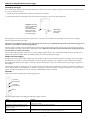
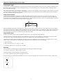
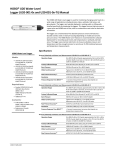
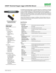
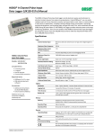
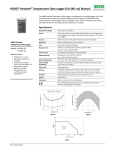
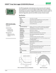
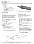
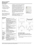
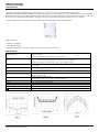
HOBO U12 Temp/RH/2
2 External Data Logger
(Part # U12-013)
Thank you for purchasing a HOBO data logger. With proper care, it will give you years of accurate and reliable measurements.
The HOBO U12 Temperature/Relative Humidity/2 External Data Logger is a four-channel logger with 12-bit resolution and can record up to 43,000
measurements or events. The two external channels accept a variety of sensors, including temperature and split-core AC current sensors as well as 420 mA and voltage input cables (sold separately). The logger uses a direct USB interface for launching and data readout by a computer.
An Onset software starter kit is required for logger operation. Visit www.onsetcomp.com for compatible software.
Inside this package:
• HOBO U12 Temp/RH/
2 External Data Logger
• Mounting kit with magnet, hook and loop tape, tie-wrap mount, tie wrap, and two screws.
Specifications
Measurement range
Accuracy
Resolution
Drift
Time accuracy
Response time in airflow of 1 m/s (2.2 mph)
Operating temperature
Battery life
Memory
Weight
Dimensions
Temperature: -20° to 70°C (-4° to 158°F)
RH: 5% to 95% RH
External input channels (see sensor manual): 0 to 2.5 DC Volts
Temperature: ± 0.35°C from 0° to 50°C (± 0.63°F from 32° to 122°F), see Plot A
RH: +/- 2.5% from 10% to 90% RH (typical), to a maximum of +/- 3.5%. See Plot B.
External input channels (see sensor manual): ± 2 mV ± 2.5% of absolute reading
Temperature: 0.03°C at 25°C (0.05°F at 77°F), see Plot A
RH: 0.03% RH
Temperature: 0.1°C/year (0.2°F/year)
RH: <1% per year typical; RH hysteresis 1%
± 1 minute per month at 25°C (77°F), see Plot C
Temperature: 6 minutes, typical to 90%
RH: 1 minute, typical to 90%
Logging: -20° to 70°C (-4° to 158°F)
Launch/readout: 0° to 50°C (32° to 122°F), per USB specification
1 year typical use
64K bytes (43,000 12-bit measurements)
46 g (1.6 oz)
58 x 74 x 22 mm (2.3 x 2.9 x 0.9 inches)
The CE Marking identifies this product as complying with all relevant directives in the European Union (EU).
© 2008 Onset Computer Corporation
Part #: MAN-U12-013, Doc #: 7662-C
HOBO U12 Temp/RH/2 External Data Logger
Connecting the logger
The U-Family logger requires an Onset-supplied USB interface cable to connect to the computer. If possible, avoid connecting at temperatures below
0°C (32°F) or above 50°C (122°F).
1. Plug the large end of the USB interface cable into a USB port on the computer.
2. Plug the small end of the USB interface cable into the bottom of the logger as shown in the following diagram.
Important: Press this
button for 3 seconds
when logger is
launched with Button
Start or press for 1
second to record an
event while logging
USB interface
cable plugged
into logger
If the logger has never been connected to the computer before, it may take a few seconds for the new hardware to be detected. Use the logger
software to launch and read out the logger.
Important: If you configure the logger to start with a button start, be sure to press and hold down the button on the front of the logger for at
least three seconds when you want to begin logging data.
Be sure to plug any external sensors (if applicable) into the side of the logger before logging begins. Also select the correct sensors and activate the
external channels in the logger software when configuring the launch. Important: If you select an external channel, but do not plug the probe in,
false data will be recorded for that channel.
You can read out the logger while it continues to log, stop it manually with the software, or let it record data until the memory is full. Refer to the
software user’s guide for complete details on launching, reading out, and viewing data from the logger.
Sample and event logging
The logger can record two types of data: samples and events. Samples are the sensor measurements recorded at each logging interval (for example,
the temperature every minute). Events are independent occurrences triggered by a logger activity. Examples of events recorded asynchronously
during deployment include when the logger is connected to the host, when the battery is low, the end of a data file once the logger is stopped, and
button pushes.
Press the button on the front of the logger for one second to record an event. Both a button up and down event will be recorded. This is useful if you
want to mark the datafile at a particular point. For example, if the logger is located in an incubator, you might press the button each time the door is
opened. The logger stores 64K of data, and can record up to 43,000 samples and events combined.
Operation
A light (LED) on the side of the logger confirms logger operation.
Channel 3
external input
Channel 4
external input
Light
The following table explains when the logger blinks during logger operation:
When:
The logger is logging
The logger is awaiting a start because it was
launched in Start At Interval, Delayed Start, or
Button Start mode
The button on the logger is being pushed for a
Button Start launch
The light:
Blinks once every one to four seconds (the shorter the logging interval, the faster the light blinks); blinks
when logging a sample
Blinks once every eight seconds until launch begins
Blinks once every second while pressing the button and then flashes rapidly once you release the button.
The light then reverts to a blinking pattern based on the logging interval
2
HOBO U12 Temp/RH/2 External Data Logger
Protecting the logger
The logger can be permanently damaged by corrosion if it gets wet. Protect it from condensation. If it gets wet, remove the battery immediately and
dry the circuit board with a hair dryer before reinstalling the battery. Do not let the board get too hot. You should be able to comfortably hold the
board in your hand while drying.
Note! Static electricity may cause the logger to stop logging. To avoid electrostatic discharge, transport the logger in an anti-static bag, and ground
yourself by touching an unpainted metal surface before handling the logger. For more information about electrostatic discharge, visit our website at
http://www.onsetcomp.com/Support/support.html.
Using external sensors
The external input channels have a switched 2.5 V output. This signal can be used to power a sensor directly or it can also be used to trigger an
external circuit. External sensors should draw no more than 4 mA total when powered. The switched 2.5 V output turns on about 15 ms before the
external channels are measured and stays powered for 48 ms after the external channels are measured, as shown in the following diagram. The striped
bar shows the 16 ms period during which the logger samples the input signals.
16 ms
15 ms
48 ms
When using multiple voltage and/or current inputs, the (-) from your current source(s) and the 0 Volt line of your voltage source(s) are tied together
at the logger. If these lines are at different voltage potentials, this may cause inaccurate readings or even damage your logger. Keep in mind that these
lines may also be tied to earth ground through your PC interface cable when connected to your computer. Special precautions may be necessary if
any of your voltage or current source common lines are not tied to earth ground.
Using the RH sensor
In order to take humidity measurements, the temperature sensor must be used in conjunction with the RH sensor.
Conditions outside the recommended range may offset the RH signal. Vapors may also affect the RH sensor. The diffusion of chemicals into the
sensor may cause a shift in both offset and sensitivity. High levels of pollutants may cause permanent damage to the sensor.
Upon returning to normal conditions, the RH sensor will slowly return towards calibration state by itself. However, prolonged exposure to extreme
conditions may accelerate aging and eventually lead to a permanent shift. To recondition the sensor, do the following:
1. Remove the battery
2. Warm 24 hours 80–90°C (176–194°F) at < 5% RH
3. Re-hydrate 48 hours 20–30°C (70–90°F) at 75–95% RH
Mounting
There are four ways to mount the logger using the materials in the mounting kit included with the logger:
• Use the hook and loop tape to affix the logger to a surface.
• Attach the magnet, then place the logger on a magnetic surface.
• Use the tie wrap and tie wrap mount to tie the logger to an object.
• Fasten the logger to a surface with the two Phillips-head screws. The back of the logger has two inserts for the screws, 32 mm (1¼ inches) apart.
32 mm
(1¼ inch)
3
HOBO U12 Temp/RH/2 External Data Logger
Battery
The logger requires one 3-Volt CR-2032 lithium battery. Expected battery life varies based on the temperature and the frequency at which the logger
is recording data (the logging interval). A new battery will typically last one year with logging intervals greater than one minute. Deployments in
extremely cold or hot temperatures or logging intervals faster than one minute may significantly reduce battery life.
To replace the battery:
1. Disconnect the logger from the computer.
2. Unscrew the logger case.
3. Lift the circuit board and carefully push the battery out with a small blunt instrument, or pull it out with your fingernail.
4. Insert a new battery, positive side facing up.
5. Carefully realign the logger case and re-fasten the screws.
WARNING: Do not cut open, incinerate, heat above 85°C (185°F), or recharge the lithium battery. The battery may explode if the logger is
exposed to extreme heat or conditions that could damage or destroy the battery case. Do not dispose of the logger or battery in fire. Do not expose
the contents of the battery to water. Dispose of the battery according to local regulations for lithium batteries.
© 2008 Onset Computer Corporation. All rights reserved.
Part #: MAN-U12-013, Doc #: 7662-C
Onset and HOBO are registered trademarks of Onset Computer Corporation. Other products and brand names may be trademarks or registered
trademarks of their respective owners.
4