1
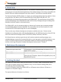
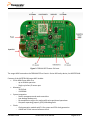
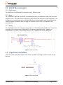
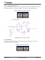
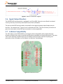
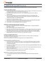
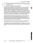
FRDM-KL02Z
User Manual
Rev. 0
Freescale Semiconductor Inc.
FRDMKL02ZUM
1. Overview
The Freescale Freedom development platform is an evaluation and development tool ideal for rapid
prototyping of microcontroller-based applications. The hardware design is form-factor compatible with
popular third-party hardware designed to work with Arduino™ and Arduino-compatible boards.
The Freescale Freedom KL02Z hardware is a simple, yet sophisticated design featuring a Kinetis L Series
microcontroller, the industry’s first microcontroller built on the ARM Cortex-M0+ core. The
KL02Z32VLK4 is the featured microcontroller on the FRDM-KL02Z. The specifications of the KL02Z32
and the flexible design of the FRDM-KL02Z enable a wide variety of design prototypes including those
dependent on battery power or harvested energy.
The FRDM-KL02Z is the first hardware platform to feature the Freescale open standard embedded
serial and debug adapter known as OpenSDA. This circuit offers the user several options for serial
communications, flash programming and run-control debugging.
There are also many software development tool options available to the user. Choices include
CodeWarrior for Microcontrollers, IAR Embedded Workbench, Keil MDK featuring the µVision IDE, Red
Suite from Code Red Technologies, Atollic TrueSTUDIO, Rowley Crossworks, and more.
All of these features combine to give the user the freedoms needed to rapidly prototype many
embedded designs: a powerful microcontroller built on a very low-power core and SoC platform, easyaccess to I/O with a large ecosystem of compatible hardware, a flexible programming and debug
interface, and a large ecosystem of software development environments. Freedom!
2. Reference Documents
OpenSDA User’s Guide
FRDM-KL02Z Quick Start Guide
FRDM-KL02Z Schematics
FRDM-KL02Z Pinouts
A guide for users of the OpenSDA embedded circuit.
This document—overview and detailed information for the
FRDM-KL02Z hardware.
PDF schematics for the FRDM-KL25Z hardware
Spreadsheet of pin connections for all MCU pins. Includes
pinout for the I/O headers, Arduino R3 compatibility chart, and
OpenSDA MCU pinout.
3. Getting Started
The FRDM-KL02 default demo shows the functionality of TSS library, PWM, Accelerometer Sensor,
Timer and I2C module. KL02 has no TSI module on chip, so in this demo the Analog Slider pad is
controlled with GPIO method by TSSW.
Use a mini USB cable to attach the FRDM-KL02Z to a USB power source (either a USB port on a
computer or a USB power supply)
The expected behavior of the demo is as follows:
FRDMKL02ZUM
FRDM-KL02Z User Manual
Page 2 of 11
1. Slide Down to Unlock.
Sliding your finger down along the TSS Pad E1 (from “2” to “1”) will unlock the tilt functionality of
the demo.
2. Tilt to adjust the LED.
With the demo “Unlocked”, tilting the board will change the RGB values displayed on the LED
3. Slide Up to Lock.
Sliding your finger up along the TSS Pad E1 (from “1” to “2”) will unlock the tilt functionality of the
demo, and the LED will only display the default color.
This example demo can be restored using the OpenSDA MSD application documented later in this User
Manual.
4. FRDM-KL02Z Hardware Overview
The FRDM-KL02Z is a microcontroller development board based on the Freescale Freedom platform
featuring the following:
• Kinetis L Series KL02 family MCU in an 32QFN package
• I/O headers for easy access to MCU I/O pins
• Freescale 3-axis accelerometer sensor, MMA8451Q
• Capacitive touch slider using GPIO method based on TSS lib
• Reset pushbutton
• RGB LED
• On-board serial and debug adapter (OpenSDA)
Touch Pad - Slider
Figure 1 shows a block diagram of the FRDM-KL02Z design.
Figure 1. FRDM-KL02Z Block Diagram
FRDMKL02ZUM
FRDM-KL02Z User Manual
Page 3 of 11
Figure 2. FRDM-KL02Z Feature Call-outs
The target MCU featured on the FRDM-KL02Z is a Kinetis L Series KL0 family device, the KL02Z32VLK4.
Features of the KL02Z32VLK4 target MCU include:
• 32-bit ARM Cortex-M0+ core
- up to 48 MHz operation
- Single-cycle fast I/O access port
• Memories
- 32 KB flash
- 4 KB SRAM
• System integration
- Power management and mode controllers
- Low-leakage wakeup unit
- Bit manipulation engine for read-modify-write peripheral operations
- Computer operating properly (COP) Watchdog timer
• Clocks
- Clock generation module with FLL for system and CPU clock generation
- 4 MHz and 32 kHz internal reference clock
FRDMKL02ZUM
FRDM-KL02Z User Manual
Page 4 of 11
•
•
•
•
- System oscillator supporting external crystal or resonator
- Low-power 1kHz RC oscillator for COP watchdog
Analog peripherals
- 12-bit SAR ADC w/ DMA support
- High speed comparator
Communication peripherals
- One 8-bit Serial Peripheral Interfaces (SPI)
- Two I2C modules
- One low-power UART
Timers
- Two 2-channel Timer/PWM modules
- Low-power Timer (LPT)
- System tick timer
Human-Machine Interfaces (HMI)
- General purpose input/output controller
5. FRDM-KL02Z Hardware Description
5.1. Power Supply
The FRDM-KL02Z offers a design with multiple power supply options. It can be powered from the USB
connector, the VIN pin on the I/O header, an on-board coin cell battery, or an off-board 1.71-3.6V
supply from the 3.3V pin on the I/O header. The USB and VIN supplies are regulated on-board using a
3.3V linear regulator to produce the main power supply. The other two sources are not regulated onboard. 0 provides the operational details and requirements for the power supplies.
Table 1. Power Supply Requirements
Supply Source
Valid Range
OpenSDA USB (J2)
VIN Pin
3.3V Pin
Coin Cell Battery
5V
4.3-9V
1.71-3.6V
1.71-3.6V
OpenSDA
Operational?
Yes
No
No
No
Regulated onboard?
Yes
Yes
No
No
Note that the OpenSDA circuit is only operational when a USB cable is connected and supplying power
to J2. However, protection circuitry is in place to allow multiple sources to be powered at once.
Figure 3 shows the schematic drawing for the power supply inputs and the on-board voltage regulator.
FRDMKL02ZUM
FRDM-KL02Z User Manual
Page 5 of 11
Figure 3. Power Supply Schematic
Table 2. FRDM-KL02Z Power Supplies
Power Supply Name
P5-9V_VIN
P5V0_USBER
P3V3_VREG
P3V3_BATT
P3V3
P3V3_MCU
P3V3_USBER
Description
Power supplied from the VIN pin of the I/O headers (J9 pin 8).
8
Power supplied from the OpenSDA USB connector (J2 and J9(pin
J9( 5)).
A Schottky diode provides back drive protection.
Regulated 3.3V supply
supply.. Sources power to the P3V3 supply rail
through a back drive protection Schottky diode. 1
Coin cell battery supply voltage. Sources power to the P3V3 supply
rail through a back drive protection Schottky diode.
Main supply rail for the FRDM-KL02Z assembly.. May be sourced from
P3V3_VREG, P3V3_BATT, or directl
directlyy from the I/O headers (J9 pin 2
and pin 44)
KL02Z MCU supply. Header J4 provides a convenient means for
energy consumption measurements. 2
OpenSDA circuit supply. Header J5 provides a convenient means for
energy consumption measurements. 2
Notes:
1) By default the linear regulator, U6
U6,, is a 3.3V output regulator. However, this
is a common footprint that would allow the user to modify the assembly to
utilize an alternative device such as a 1.8V or 2.5V regulator. The KL02Z
microcontroller has an operating range of 1.71V to 3.6V.
2) J4 and J5 are not populated by default. The two pins of these headers are
shorted together by a trace on the bottom layer of the PCB. To measure the
energy consumption of either the KL02Z or the OpenSDA MCU, the trace
between these pins
ns must first be cut. A current probe or a shunt resistor and
voltage meter can then be applied to measure the energy consumption on these
rails.
FRDMKL02ZUM
FRDM-KL02Z User Manual
Page 6 of 11
5.2. KL02Z Microcontroller
5.2.1. Clock Source
The KL02Z32 on the FRDM-KL02Z is clocked from a 32.768KHz crystal.
5.2.2. Reset
The PTA20/RESET signal on the KL02Z32 is connected externally to a pushbutton, SW1, and also to the
OpenSDA circuit. The reset button can be used to force an external reset event in the target MCU. The
reset button can also be used to force the OpenSDA circuit into bootloader mode (Press and hold the
Reset/Bootloader pushbutton while you plug in a USB cable (A to mini-B) to the OpenSDA USB
connector (J2)).
5.2.3. Debug
The sole debug interface on all Kinetis L Series devices is a Serial Wire Debug (SWD) port. The primary
controller of this interface on the FRDM-KL02Z is the onboard OpenSDA circuit. However, an
unpopulated 10-pin (0.05”) Cortex Debug connector, J1, provides access to the SWD signals.
Figure 4. SWD connector
5.3. Capacitive Touch Slider
Two Touch Sense Input (GPIO) signals, GPIO PTA13 and PTB12 controlled by TSS lib emulate the TSI
function.
Figure 5. GPIO Touch Pad
FRDMKL02ZUM
FRDM-KL02Z User Manual
Page 7 of 11
5.4. 3-axis Accelerometer
A Freescale MMA8451Q low-power, three-axis accelerometer is interfaced through an I2C bus and two
GPIO signals as shown in Table 3 below. By default, the I2C address is 0x1D (SA0 pulled high).
Table 3. Accelerometer Signal Connections
MMA8451Q
SCL
SDA
INT1
INT2
KL02Z32
PTB3
PTB4
NC
PTA10
Figure 6. MMA8451Q Schematic Diagram
5.5. RGB LED
Three PWM-capable KL02Z32 signals are connected to a red, green and blue LED. The signal
connections are shown in Table 4 below.
Table 4. RGB LED Signal Connections
RGB LED
Red Cathode
Green Cathode
Blue Cathode
FRDMKL02ZUM
KL02Z128
PTB6
PTB7
PTB10
FRDM-KL02Z User Manual
Page 8 of 11
Figure 7. RGB LED Schematic Diagram
5.6. Input/Output Headers
The KL02Z32VLK4 microcontroller is packaged in an 32-pin QFN. Some pins are utilized in on-board
circuitry, but many are directly connected to one of four I/O headers.
The pins on the KL02Z microcontroller are named for their general purpose input/output port pin
function. For example, the 1st pin on Port A is referred to as PTA1. The I/O connector pin names are
given the same name as the KL02Z pin connected to it, where applicable.
5.7. Arduino Compatibility
The I/O headers on the FRDM-KL02Z are arranged to allow compatibility with peripheral boards
(known as shields) that connect to Arduino and Arduino-compatible microcontroller boards. The outer
rows of pins (the even numbered pins) on the headers share the same mechanical spacing and
placement as the I/O headers on the Arduino Uno Revision 3 board design.
Figure 8. FRDM-KL02 Pinout
FRDMKL02ZUM
FRDM-KL02Z User Manual
Page 9 of 11
6. FRDM-KL02Z OpenSDA Overview
By default the FRDM-KL02Z board comes pre-programmed with the OpenSDA Bootloader.
Using the OpenSDA Bootloader
1. Press and hold the Reset/Bootloader pushbutton while you plug in a USB cable (A to mini-B) to
the OpenSDA USB connector (J2). Release the pushbutton.
2. The FRDM-KL02Z should enumerate as a mass-storage device with a volume label of
"BOOTLOADER".
3. You may now drag/drop or copy/paste OpenSDA applications (e.g. Debug App, MSD
Programming App, CMSIS-DAP) to your OpenSDA drive. Applications can be found in the
"applications" folder of the OpenSDA package.
4. Unplug the USB cable and plug it in again
(Note: this is a step that will not be required on future versions of the OpenSDA bootloader)
5. You should now be running the programmed OpenSDA application.
6. To boot back into the Bootloader, start over at step #1.
Reading the installed OpenSDA hardware information
1. Boot into the OpenSDA bootloader mode by following the steps in "Using the OpenSDA
Bootloader" section.
2. Open "BOOTLOADER" mass-storage device drive.
3. Open SDA_INFO.HTM file with any web browser. An HTML page will open with your Freedom
OpenSDA hardware information; including bootloader and application installation details.
4. This HTML page will also include links to download the latest OpenSDA Firmware (MSD &
Debug applications) as well as USB Drivers for OpenSDA CDC device.
Installing the OpenSDA CDC Drivers
The Debug and MSD applications both include a CDC device for USB serial port. The following
instructions are specific to Windows 7.
(Note: Driver installation for other operating systems may be slightly different)
Recommended Driver Installation Process
1. Download the latest “Windows USB Drivers” from the OpenSDA Support page accessed by
selecting the “SDA_INFO.HTM” link located on mass-storage device enumerated from the
connected FRDM-KL02Z
2. Disconnect the FRDM-KL02Z from the host PC and install the downloaded Windows USB Driver
installation executable.
3. Once the installation is complete, plug in your board that has be programmed with either the
MSD or Debug application.
4. Windows should automatically enumerate as an OpenSDA – CDC Serial Port.
If the driver enumeration fails, the driver can be ma
Manual Driver Installation Process using the include INF file
1. If not already programmed, install the OpenSDA MSD Application using the OpenSDA
Bootloader.
FRDMKL02ZUM
FRDM-KL02Z User Manual
Page 10 of 11
2. Open the Device Manager (e.g. Control Panel -> System and Security -> System -> Device
Manager, or just type “Device Manager” in the search box of the Start Menu and hit Enter)
3. Look under “Other Devices” and locate the device with CDC in the name. Right click this device
and choose “Update Driver Software”.
4. Choose to “Browse” for the driver and navigate to the enumerate Mass-Storage Device drive
(“FRDM-KL02Z”)
5. Click “Install” and follow the on-screen prompts.
You should now have a new COM port under the Ports section in Device Manager. You can use any
terminal emulation program to connect to the COM port.
The default COM settings are….
Using the OpenSDA MSD Application to Program the KL02Z
1. If not already programmed, install the OpenSDA MSD Application using the OpenSDA
Bootloader.
2. The OpenSDA application will enumerate as a Mass-Storage Device drive.
3. While running the MSD Application, drag/drop or copy/paste one of the precompiled S-record
or binary files into the MSD drive. The application file will automatically be programmed and
executed on the KL02Z.
Using the OpenSDA P&E Debug Application
1. Download and Install the latest “Windows USB Drivers” from the OpenSDA Support page
accessed by selecting the “SDA_INFO.HTM” link located on mass-storage device enumerated
from the connected FRDM-KL02Z
2. Install the OpenSDA P&E Debug Application using the OpenSDA Bootloader.
3. Following a power cycle, the board should enumerate as a "PEMicro OpenSDA Debug
Driver" device
4. You now have working environment within CodeWarrior 10.3.
FRDMKL02ZUM
FRDM-KL02Z User Manual
Page 11 of 11