1
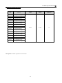
Table of Contents
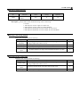
1. Inspection upon receiving
P3
2. Installation and storage
P4
A. FG/FP exterior dimension
P5
B. E2 exterior dimension
P6
C. Standard specifications
P7
3. Wiring diagram
P14
A. Wiring of main and control circuit
P14
B. Signal circuit
P14
C. Connecting the power supply and the AC motor
P14
D. R.S.T. for Power source reacto r
P15
E. FG/FP standard external connection diagram
P16
F. E2 standard external connection diagram
P19
G. Terminal functions
P22
4. Digital Operator
P23
A. Keys functions
P23
B. Keypad operation
P26
C. LCD Keypad Copy functions
P30
5. User constants
P32
6. Constants tables
P33
7. Motor autotuning
P47
8. Constant setting by function
P49
A. Setting frequency
P49
B. Selecting frequency command
P51
C. Operation command
P52
D. Setting acceleration/ deceleration
P52
E. Stopping mode
P53
F. Jump brake
P53
G. DC brake
P55
9. Output/ input terminals
P56
B. Analog output setting
C. Multi-functional terminal setting
D. Jog frequency
E. Multi-speed frequency command
P56
F. Multi-functional relay setting
P62
10. V/F control
P64
A. V/F curve selecting
P64
B. Frequency command limit
P67
C. Torque boost, torque boost gain
P68
D. Motor rated current
P69
11. PID control
P70
A. Multi-functional analog input
1
P57
P58
P59
P60
12. Multi-step function
P74
13. Series communication user manual
P79
A. The physical link
P79
B. Data structure in communication
P83
C. Error check generation
P84
14. Protections
P86
A. Preventing motor stalling function
P86
B. Motor search speed function
P90
C. Instantaneous current handling
P92
D. Overheating protection
P93
15. Environment setting
P94
A. Dynamic brake
P94
B. Carrier wave frequency
P95
C. Lock data
P97
D. Setting LCD keypad functions
P99
E. Recovering factory settings
P101
16. Troubleshooting
P102
17. Control procedures chart
P104
2
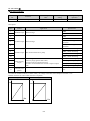
1. Inspection upon receiving ■
Preface
Thank you for choosing the CT-2000FG/ FP/ E2 inverter unit, this inverter unit is suitable for operating squirrel cage
induction motors. This manual is designed to ensure correct and suitable application. Read this manual before
attempting to install. If any problem occurred when negligence of manual. Please contact our distributors or sales
representatives.
※Application notes
▇ Please do not touch the cercuit boards and components immediately after the poweris was shut down.
▇ Wiring is prohibited when power on, please do not check the components and signal on the circuit board when
operation.
▇ Do not fit capacitors to the output side of the inverter in order to improve the power ratio.
▇ Run a motor that is within the capacity of the inverter unit.
▇ In case of fitting MC between inverter and motor to control motor operation, then the capacity of inverter must
be 6 times the capacity of motor.
Inspection upon receiving
A. Check that the model, the capacity and power voltage specifications are as ordered.
B. Check that no damage has occurred during transportation.
C. Check that none of the internal parts have been damaged or have fallen off.
D. Check that none of the connectors have been damaged or have fallen off.
E. Check that there is no loosening of the terminals or screws of each of the parts.
If said problems occurred when negligence of manual. Please contact our distributors or sales representatives
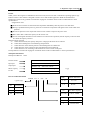
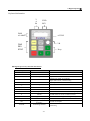
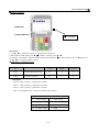
Nameplate information
Example for 5HP/3A7
220V
Inverter model
MODEL:
Input spec.
INPUT : 3Φ
Output spec.
OUTPUT: 3Φ
Motor capacity
Motor:3.7KW/5HP
Lot No.
LOT NO:
CT2000FG-2-3A7-A1
220V 50//60HZ 21A
220V 18A 7.1KVA
Inverter model information
CT2000
FG – 2
weight
Mass:8.0Kg
No.
-3A7
CT2000 series
Outline dimension
-A1
1~10
A1~A10
1~2
B1~B2
No.
Specification
FG
150% load
FP
120% load
No.
Max. Motor capacity
E2
150% load
3A7~300
3.7KW~300KW
No.
Input voltage class
2
AC 200~240V
4
AC380~460V
3
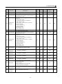
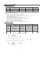
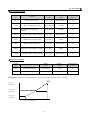
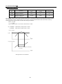
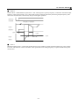
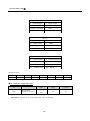
2. Installation and storage ■
Installation and storage
1. Storage: If the equipment is not to be installed immediately, it should be stored in a clean and dry location at
ambient temperatures from 20℃to 55℃. The surrounding air must be free of corrosive contaminants. And
please input power a time per half year.
2. Installation place: Places where the peripheral temperature is from -10℃to 40℃, and where the relative
humidity is 90% or less. Avoid installing at places where there is dust, iron particles, corrosive gas, water
spray, direct sunlight or too much vibration. And places where has good ventilation.
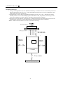
3. Please fix the inverter under the cooling fan if it is installed in the panel. The heating from inverter will be
discharged out of the panel to reduce the temperature and get the better effect of ventilation.
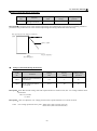
Notice : 10HP(contained) and above inverter are installed as following.
Discharge heating
FAN
Heating of inverter
10~20 cm
10cm
10cm
CT2000F□
30 cm at least
4
2. Installation and storage ■
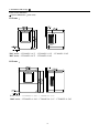
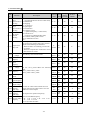
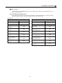
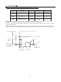
A. FG/FP exterior dimension
◆ Inverter dimensions:(unit:: mm)
A1 Frame
(without LCD keypad)
D
F
A2~A4
A6~A10
G
A
B
C
D
E
F
G
H
A2
430
414
401
244
190
225
7
Φ7
A3
472
456
441
260
208
258
7
Φ7
A4
492
477
466
283
200
289
7
Φ7
A5
560
546.5
523
330
246
315
7
Φ7
A6
699
679
668
408
270
323
10
Φ10
A7
928
908
872
530
350
323
10
Φ10
A8
1162
1142
1106
530
350
335
10
Φ10
A9
*
*
*
*
*
*
*
*
A10
1480
1460
1415
710
350
415
10
Φ10
(If the specification change not seperately informs)
“ * “ means under development
5
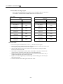
2. Installation and storage ■
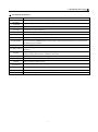
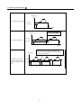
B. E2 exterior dimension
◆ Inverter dimensions:(unit:: mm)
B1 Frame︰
220V series:CT2000E2-2-A37、CT2000E2-2-A75、CT2000E2-2-1A5
380V series︰CT2000E2-4-A75、CT2000E2-4-1A5
B2 Frame︰
220V series:CT2000E2-2--2A2、CT2000E2-2--3A7
380V series:CT2000E2-4--2A2、CT2000E2-4--3A7、CT2000E2-4--5A5
6
2. Installation and storage ■
◆ FG standard specification
Control method
V/F vector PWM control
Frequency accuracy Digital setting:±0.01
Frequency
Digital setting:0.01 HZ
resolution
Frequency range 0.00 ~ 400.00 HZ
V/F ratio
Torque boost
Acce./ Dece. time
Analog setting:± 0.5%(35℃)
Analog setting:(Max. frequency/1024)HZ
14 patterns, or any V/F patterns.
Motor autotuning, automatic torque boost (1HZ torque above 150%)
0.0 ~ 6000.0 sec.(linear, two-step setting)
Brake
DC, dynamic brake (below 11KW)
150% overload, jogging speed, upper/lower frequency limit setting, 8-step speed setting,
Standard feature multi-step function, RS485/RS422 communication, jump frequency, PID control, multi-function
DI & analog input interface
Option card features Analog-digital IO card (under development)
Frequency setting
Display
Protection
Digital setting by keypad, analog setting by keypad(DC 0~10V), analog setting(DC 0~10V、
4~20mA)
LCD display, 7-segment LED display, frequency, current,
voltage, setting value, function, indicators, fault status
Out of phase, low voltage, over voltage, overload, over current, over heating, subthreshold current
Overload capacity 150% for 1 min, anti-time limit function
Altitude
Ambient
Temperature
Vibration
Humidity
Indoor, altitude 1,000m or lower,
-10℃ ~ 50℃, below 7.5KW (-10℃ ~ 45℃)
Below 0.5 G
Relative between 45﹪ to 90% (No condensing)
Protection structre Forced air cooling, IP00 (below 7.5KW IP20)
7
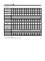
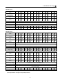
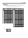
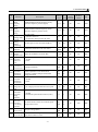
2. Installation and storage ■
FG 200V series
Motor rating
(KW)
Model
(CT-2000FG-2)
Rated current
(A)
Rated capacity
(KVA)
3.7
5.5
7.5
11
15
18
22
30
37
45
55
75
93
112
3A7
5A5
7A5
011
015
018
022
030
037
045
055
075
093
112
18
23
33
48
61
75
86
125
150
170
210
278
330
390
7.1
9.2
13.1
19.1
24.3
29.9
34.3
49
60
68
84
111
131
156
Rated input voltage
3φ200~230V ±10%,50 / 60HZ ±5%
Rated output voltage
3φ200~230V ±10%
Cooling system
Forced air-cooling
Outline dimension
A1
A1
A1
A2
A3
A4
A4
A5
A5
A6
A6
A7
A7
A7
Weight (kg)
8
9
10
14
20
22
22
45
45
65
65
70
70
70
131
160
131
160
470
580
187
231
Motor rating
(KW)
Model
(CT-2000FG-2)
Rated current
(A)
Rated capacity
(KVA)
Rated input voltage
3φ200~230V ±10%,50 / 60HZ ±5%
Rated output voltage
3φ200~230V ±10%
Cooling system
Forced air-cooling
Outline dimension
A8
A8
Weight (kg)
123
125
“ * “ means under development
(If the specification change not seperately informs)
8
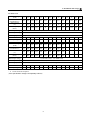
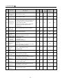
2. Installation and storage ■
FG 400V series
Motor rating
(KW)
Model
(CT-2000FG-4)
Rated current
(A)
Rated capacity
(KVA)
3.7
5.5
7.5
11
15
18
22
30
37
45
55
75
93
112
3A7
5A5
7A5
011
015
018
022
030
037
045
055
075
093
112
9
13
17.3
24
31
39
52
65
78
93
110
156
180
225
7.1
10.4
13.8
19.1
24.7
31
41.4
51.8
62.1
74
87.6
124
143
180
Rated input voltage
3φ380~460 ±10%,50 / 60HZ ±5%
Rated output voltage
3φ380~460 ±10%
Cooling system
Forced air-cooling
Outline dimension
A1
A1
A1
A1
A2
A3
A4
A4
A5
A5
A6
A6
A6
A7
Weight (kg)
9
9
9
9
14
14
23
23
40
46
50
55
60
70
131
160
187
225
262
315
400
450
560
635
131
160
187
225
262
315
400
450
560
635
260
305
370
460
530
610
700
800
990
1120
207
243
295
366
422
485
557
637
788
892
Motor rating
(KW)
Model
(CT-2000FG-4)
Rated current
(A)
Rated capacity
(KVA)
Rated input voltage
3φ380~460 ±10%,50 / 60HZ ±5%
Rated output voltage
3φ380~460 ±10%
Cooling system
Forced air-cooling
Outline dimension
A7
A7
A8
A8
A10
A10
A10
A10
A11
G11
Weight (kg)
93
95
123
123
200
200
200
200
350
*
“ * “means under development
(If the specification change not seperately informs)
9
2. Installation and storage ■
◆ FP standard specification
Control method
V/F vector PWM control
Frequency accuracy Digital setting:±0.01
Frequency
Digital setting:0.01 HZ
resolution
Frequency range 0.00 ~ 400.00 HZ
V/F ratio
Torque boost
Acce./ Dece. time
Analog setting:± 0.5%(35℃)
Analog setting:(Max. frequency/1024)HZ
14 patterns, or any V/F patterns.
Motor autotuning, automatic torque boost (1HZ torque above 150%)
0.0 ~ 6000.0 sec.(linear, two-step setting)
DC、dynamic brake (below 11KW)
120% overload, jogging speed, upper/lower frequency limit setting, 8-step speed setting,
Standard feature multi-step function, RS485/RS422 communication, jump frequency, PID control, multi-function
DI & analog input interface
Option card features Analog-digital IO card (under development)
Brake
Frequency setting
Display
Protection
Digital setting by keypad, analog setting by keypad(DC 0~10V), analog setting(DC 0~10V、
4~20mA)
LCD display, 7-segment LED display, frequency, current,
voltage, setting value, function, indicators, fault status
Out of phase, low voltage, over voltage, overload, over current, over heating, subthreshold current
Overload capacity 120% for 1 min, anti-time limit function
Altitude
Ambient
Temperature
Vibration
Humidity
Indoor, altitude 1,000m or lower,
-10℃ ~ 45℃
Below 0.5 G
Relative between 45﹪ to 90% (No condensing)
Protection structre Forced air cooling, IP00
10
2. Installation and storage ■
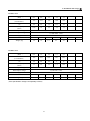
FP 200V series
Motor rating
(KW)
Model
(CT-2000FP-2)
Rated current
(A)
Rated capacity
(KVA)
11
15
18
22
30
37
45
55
75
93
112
130
150
187
011
015
018
022
030
037
045
055
075
093
112
130
150
187
48
61
75
86
125
150
170
210
278
330
390
470
530
700
19.1
24.3
29.9
34.3
49
60
68
84
111
131
156
187
211
279
Rated input voltage
3φ200~230V ±10%,50 / 60HZ ±5%
Rated output voltage
3φ200~230V ±10%
Cooling system
Forced air-cooling
Outline dimension
A2
A2
A4
A4
A4
A5
A5
A6
A6
A7
A7
A8
A8
A10
Weight (kg)
14
14
20
22
22
45
46
48
50
70
70
123
123
*
11
15
18
22
30
37
45
55
75
93
112
130
150
187
011
015
018
022
030
037
045
055
075
093
112
130
150
187
24
31
38
47
65
74
93
110
156
180
225
246
290
370
19.1
24.7
30.2
37.4
51.8
59
74
87.6
124
143
180
196
231
295
FP 400V series
Motor rating
(KW)
Model
( CT-2000FP-4)
Rated current
(A)
Rated capacity
(KVA)
Rated input voltage
3φ380~460 ±10%,50 / 60HZ ±5%
Rated output voltage
3φ380~460 ±10%
Cooling system
Forced air-cooling
Outline dimension
A1
A2
A2
A3
A4
A4
A5
A5
A6
A6
A7
A7
A7
A8
Weight (kg)
10
14
14
20
20
22
40
46
50
55
65
70
93
123
220
250
315
400
450
560
710
800
220
250
315
400
450
560
710
800
415
506
600
700
800
990
1260 1460
330
402
478
557
637
788
1003 1163
Motor rating
(KW)
Model
(CT-2000FP-4)
Rated current
(A)
Rated capacity
(KVA)
Rated input voltage
3φ380~460 ±10%,50 / 60HZ ±5%
Rated output voltage
3φ380~460 ±10%
Cooling system
Forced air-cooling
Outline dimension
A8
A8
A10
A10
A10
A11
A11
A11
Weight (kg)
123 123
200
“ * “ means under development
200
200
350
350
*
(If the specification change not seperately informs)
11
2. Installation and storage ■
◆ E2 standard specification
Control method
V/F vector PWM control
Frequency accuracy Digital setting:±0.01
Frequency
Digital setting:0.01 HZ
resolution
Frequency range 0.00 ~ 400.00 HZ
V/F ratio
Torque boost
Acce./ Dece. time
Analog setting:± 0.5%(35℃)
Analog setting:(Max. frequency/1024)HZ
14 patterns, or any V/F patterns.
Motor autotuning, automatic torque boost (1HZ torque above 150%)
0.0 ~ 6000.0 sec.(linear, two-step setting)
Brake
DC, dynamic brake
150% overload, jogging speed, upper/lower frequency limit setting, 8-step speed setting,
Standard feature multi-step function, RS485/RS422 communication, jump frequency, PID control, multi-function
DI & analog input interface
Option card features Analog-digital IO card
Frequency setting
Display
Protection
Digital setting by keypad, analog setting by keypad(DC 0~10V), analog setting(DC 0~10V、
4~20mA)
LCD display, 7-segment LED display, frequency, current,
voltage, setting value, function, indicators, fault status
Out of phase, low voltage, over voltage, overload, over current, over heating, subthreshold current
Overload capacity 150% for 1 min, anti-time limit function
Altitude
Ambient
Temperature
Vibration
Humidity
Indoor, altitude 1,000m or lower,
-10℃ ~ 50℃, below 7.5KW (-10℃ ~ 45℃)
Below 0.5 G
Relative between 45﹪ to 90% (No condensing)
Protection structre Forced air cooling, IP20
12
2. Installation and storage ■
E2 200V series
Motor rating
(KW)
Model
(CT-2000E2-2)
Rated current
(A)
Rated capacity
(KVA)
037
075
1.5
2.2
3.7
A37
A75
1A5
2A2
3A7
2.4
4.2
7.4
11.1
18
0.96
1.8
2.9
4.4
7.1
Rated input voltage
3φ200~230V ±10%,50 / 60HZ ±5%
Rated output voltage
3φ200~230V ±10%
Cooling system
Forced air-cooling
Outline dimension
B1
B1
B1
B2
B2
Weight (kg)
1.6
1.6
1.6
2.5
2.5
075
15
2.2
3.7
5.5
A75
1A5
2A2
3A7
5A5
2.2
4.0
6.2
9
13
1.7
3.2
4.9
7.1
10.4
E2 400V series
Motor rating
(KW)
Model
( CT-2000E2-4)
Rated current
(A)
Rated capacity
(KVA)
Rated input voltage
3φ380~460 ±10%,50 / 60HZ ±5%
Rated output voltage
3φ380~460 ±10%
Cooling system
Forced air-cooling
Outline dimension
B1
B1
B2
B2
B2
Weight (kg)
1.6
1.6
2.5
2.5
2.5
(If the specification change not seperately informs)
13
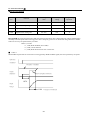
3. Wiring diagram■
Wiring diagram
◆ Wiring the master circuit and control circuit
Wire according to the standard connection diagram. On using the external sequence control, please use
small signal relay or double terminal relay to avoid relay terminal malfunction.
◆ Signal wire
The signal circuit uses either shielded pairs or twisted pairs, should be wired either using a wiring duct
separated from that for the power circuit, or with the wiring conduit isolated as much as possible.
◆ Wiring between main circuit and motor
Connect the main circuit, by wiring according to the main circuit terminal connection diagram. Care is
required not to make a mistake when connecting the input and output terminals, lest it will cause
inverter damage. Specifications of main circuit path and NFB are as following:
Voltage
Model
(V)
CT2000E2-2-A4
CT2000E2-2-A75
CT2000E2-2-1A5
CT2000E2-2-2A2
CT2000E2-2-3A7
CT-2000FG-2-3A7
CT-2000FG-2-5A5
CT-2000FG-2-7A5
CT-2000F□-2-011
CT-2000F□-2-015
220 CT-2000F□-2-022
CT-2000F□-2-030
CT-2000F□-2-037
CT-2000F□-2-045
CT-2000F□-2-055
CT-2000F□-2-075
CT-2000F□-2-093
CT-2000F□-2-112
CT-2000F□-2-131
CT-2000FP-2-150
CT-2000FG-2-160
CT-2000FP-2-187
NFB Standard wiring
(A)
2
(mm )
10
2.0
10
2.0
15
2.0
20
2.0
30
3.5~5.5
30
3.5~5.5
30
5.5~8
40
5.5~8
60
22
80
30
120
38
150
38~100
200
38~100
250
60~100
300
100
400
100~200
500
100~200
500
100~200
600
100~200
800
200
800
200
800
200~300
*CT2000F□
No.
Specification
G
150% load
P
120% load
Voltage
Model
(V)
CT2000E2-4-A75
CT2000E2-4-1A5
CT2000E2-4-2A2
CT2000E2-4-3A7
CT2000E2-4-5A5
CT-2000FG-4-3A7
CT-2000FG-4-5A5
CT-2000FG-4-7A5
380
CT-2000F□-4-011
| CT-2000F□-4-015
460 CT-2000F□-4-022
CT-2000F□-4-030
CT-2000F□-4-037
CT-2000F□-4-045
CT-2000F□-4-055
CT-2000F□-4-075
CT-2000F□-4-093
CT-2000F□-4-112
CT-2000F□-4-130
CT-2000FP-4-150
CT-2000FG-4-160
CT-2000F□-4-187
CT-2000FP-4-220
CT-2000FG-4-225
CT-2000FP-4-250
CT-2000FG-4-262
CT-2000FP-4-300
CT-2000FG-4-315
CT-2000FG-4-370
14
NFB Standard wiring
(A)
2
(mm )
10
2.0
10
2.0
10
2.0
15
3.5~5.5
15
3.5~5.5
15
3.5~5.5
15
3.5~5.5
20
5.5
30
8~14
40
8~14
60
22
80
22
100
30
120
50
150
38~100
200
38~100
250
60~100
300
60~100
300
100
400
100~200
400
100~200
500
100~200
600
100~200
600
100~200
800
200
800
200
800
200~300
800
200~300
900
300
3. Wiring diagram■
◆ AC Reactor ( ACL )
The main purpose for fitting A.C.L. at the R.S.T. input side is to curb instantaneous current and to
improve ratio, it should be fitted the A.C.L. to R.S.T. input side under the following circumstance:
A. Where power system capacity is over 500KVA.
B. Using thyrister, phase advance capacity etc. for the same power supply.
Inductance of Power side from R.S.T of Inverter(A.C.L)
Voltage
Model
(V)
CT-2002E2-2-A4
CT-2002E2-2-A75
CT-2002E2-2-1A5
CT-2002E2-2-2A2
CT-2002E2-2-3A7
CT-2000FG-2-3A7
CT-2000FG-2-5A5
CT-2000FG-2-7A5
CT-2000F□-2-011
CT-2000F□-2-015
CT-2000F□-2-018
CT-2000F□-2-022
220 CT-2000F□-2-030
CT-2000F□-2-037
CT-2000F□-2-045
CT-2000F□-2-055
CT-2000F□-2-075
CT-2000F□-2-093
CT-2000F□-2-112
CT-2000F□-2-131
CT-2000FP-2-150
CT-2000FG-2-160
CT-2000FP-2-187
Current Inductance
value
(Ar.m.s)
6A
1.8 mH
6A
1.8 mH
10A
1.1 mH
15A
0.71 mH
20A
0.53 mH
20A
0.53mH
30A
0.35mH
40A
0.26mH
60A
0.18mH
80A
0.13mH
90A
0.12mH
120A
0.09mH
150A
70uH
200A
50uH
250A
44uH
300A
35uH
400A
27uH
500A
21uH
600A
21uH
600A
17 uH
600A
17 uH
600A
17 uH
750A
15 uH
Voltage
CT-2004E2-4-A75
CT-2004E2-4-1A5
CT-2004E2-4-2A2
CT-2004E2-4-3A7
CT-2004E2-4-5A5
CT-2000FG-4-3A7
CT-2000FG-4-5A5
CT-2000FG-4-7A5
CT-2000F□-4 -011
CT-2000F□-4-015
CT-2000F□-4-018
CT-2000F□-4-022
CT-2000F□-4-030
380 CT-2000F□-4-037
| CT-2000F□-4-045
460 CT-2000F□-4-055
CT-2000F□-4-075
CT-2000F□-4-093
CT-2000F□-4-112
CT-2000F□-4-131
CT-2000FP-4-150
CT-2000FG-4-160
CT-2000F□-4-187
CT-2000FP-4-220
CT-2000FG-4-225
CT-2000FP-4-250
CT-2000FG-4-262
CT-2000FP-4-300
CT-2000FG-4-315
*CT2000F□
No.
Specification
G
150% load
P
120% load
Model
(V)
15
Current
value
(Ar.m.s)
5A
5A
7.5A
10A
15A
10A
15A
20A
30A
40A
50A
60A
80A
100A
120A
150A
200A
250A
300A
300A
330A
330A
380A
490A
490A
660A
660A
660A
660A
Inductance
4.2 mH
4.2 mH
3.6 mH
2.2 mH
1.42mh
2.2mH
1.42mH
1.0mH
0.7mH
0.53mH
0.42mH
0.36mH
0.26mH
0.21mH
0.18mH
0.14mH
0.11mH
0.10mH
70uH
70uH
60uH
60uH
50uH
40uH
40uH
30uH
30uH
30uH
30uH
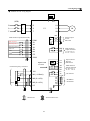
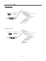
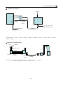
3. Wiring diagram■
◆ Standard external wiring diagram
DBR
)
P
NFB
R
A
R
S
C
S
L
T
T
DBU
PN
R
PR N
U
V
FG /FP
IM
W
Multi-function input(DI terminal)
COM
S1
Multi-step time 1
Multi-step time 2
FM
S2
S3
S4
Multi-step speed set 2
Fault reset
3-wire operation
CC
MA
MB
MC
S5
Free run stop
control
S6
REV
RR
FWD
Analog output
0~10V
Max 5mA
AM
M1
M2
M3
FR
COM
P1
PC
Extemal frequency references
Multi-function
Output terminals 1
AC 240V Max 1A
DC 28V Max 2A
Multi-function
Output terminals 2
Open collector
DC 48V
Max 50mA
10V
4~20mA
2k Ω
2k Ω
IN1 ( 4~20mA)
TA
IN2 (0~+10V)
TB
RA
IN3 (0~+10V)
RB
IG
CC
EG
Twisted shield wirse
Shield wirse
16
MODBUS
RS422/485
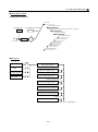
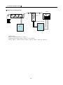
3. Wiring diagram■
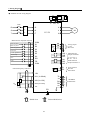
◆ Terminals arrangement:
C16D230
IU
(Control board 1)
IV
IW
Option card connector
RS 485 / 422
Multi-function
Output terminals
KEYPAD
Communication
terminals
M2 M1 M3 MB MA MC
TA TB RA RB IG EG
N02 NC2
+
R
A- +
S
Analog input
terminals
Open collector
Multi-function terminals
10V IN1 IN2 IN3 CC FM AM CC
B
P1 PC COM S1 S2 S3 S4
S5 S6
E1
RR FR COM
V
T
E
U
V
W
P
PR
Master circuit
Terminals
(A1~A2)
R
S
T
E
U
V
W
N
P
※C16D230(Control board 2): Under development, applies to new structure.
17
P
Master circuit
terminals
(A3~A4)
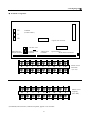
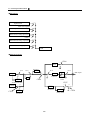
3. Wiring diagram■
◆ Terminals arrangement:
IU
IV
C16D225
(Control board 1)
IW
Option card connector
RS 485 / 422
Multi-function
Output terminals
KEYPAD
M2 M1 M3 MB MA MC
TA TB RA RB IG EG
+
R
Analog input
terminals
Communication
terminals
A- +
10V IN1 IN2 IN3 CC FM AM CC
B
S
Open collector
Multi-function terminals
P1 PC COM S1 S2 S3 S4
S5 S6
E1
RR FR COM
V
T
U
V
W
N
P
Master circuit
terminals
(A5~A10)
U
V
E
.
※C16D230(Control board 2): Under development, applies to new structure
◆ Option card:AI /AO card (Under development)
18
W
N
P
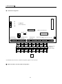
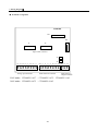
3. Wiring diagram■
◆ Standard external wiring diagram
DBR
)
(NFB)
P
A
C
L
R
S
T
PR
R
U
E2
S
V
T
IM
W
FM
Analog output
0~10V
Max 5mA
Multi-function input(DI terminal)
AM
COM
S1
Multi-step time 1
Multi-step time 2
CC
S2
S3
S4
Multi-step speed set 2
Fault reset
REV
MA
MB
MC
RR
FWD
Multi-function
Output terminals
AC 240V Max 1A
DC 28V Max 2A
FR
COM
P1
PC
Option card
C16D244
M1
M2
M3
Extemal frequency references
10V
S5
S6
COM
4~20mA
2k Ω
IN1 ( 4~20mA)
TA
TB
RA
RB
IG
IN2 (0~+10V)
2k Ω
IN3 (0~+10V)
CC
EG
Shield wirse
Twisted shield wirse
19
Open collector
DC 48V
Max 50mA
Multi-function
Output terminals
AC 240V Max 1A
DC 28V Max 2A
DI terminal
MODBUS
RS422/485
3. Wiring diagram■
◆ Terminals arrangement
C16D248
JP1
JP2
J1
J2
Option card connector
J3
J4
+10V IN1 IN2 IN3 CC FM AM CC
COM S1
S2
S3
S4
RR FR COM MB
MA MC
+10V IN1 IN2 IN3 CC FM AM CC
COM S1
S2
S3
S4
RR FR COM MB
MA MC
Analog input terminals
Multi-function terminals
Multi-function
Output terminals
220V series︰CT2000E2-2-A37、 CT2000E2-2-A75、CT2000E2-2-1A5
380V series︰CT2000E2-4-A75、 CT2000E2-4-1A5
20
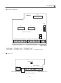
3. Wiring diagram■
◆ Terminals arrangement
JP1
C16D243
JP2
J1
J2
Option card connector
J3
J4
+10V IN1 IN2 IN3 CC FM AM CC
COM S1
S2
S3
S4
RR FR COM MB
MA MC
+10V IN1 IN2 IN3 CC FM AM CC
COM S1
S2
S3
S4
RR FR COM MB
MA MC
Analog input terminals
Multi-function
Output terminals
Multi-function terminals
220V series︰CT2000E2-2-2A2、CT2000E2-2-3A7
380V series︰CT2000E2-4-2A2、CT2000E2-4-3A7、CT2000E2-4-5A5
◆ Option card
RS 485 / 422
Open collector
M2
M1
M3
TA TB
RA RB
IG
EG
P1
PC
S5
S6 COM
P1
PC
S5
S6 COM
KEYPAD
M2
M1
M3
Multi-function Output
TA TB
RA RB
IG
EG
Communication terminals
21
Multi-function Output
3. Wiring diagram■
◆ Terminal Specification:
Classification
Main Circuit
Analog input/
output terminal
Terminal
symbol
Terminal name
R.S.T
AC power input terminal
3ΦAC 200~240V 50/60HZ
3ΦAC 380~460V 50/60HZ
U.V.W
Inverter output terminal
3-phase induction motor
E
Ground Terminal
P、PR
Breaking unit connecting terminal
P、N
Breaking resistor connecting termial
Connected with brake unit DBU
10V
+10V power outout
Provide +10VDC 30mA power
CC
Common of analog input/ output
IN1
Multi-function analog input 1
4~20mA input
IN2
Multi-function analog input 2
0~10V input
IN3
Main speed analog input 3
0~10V input
FM
AM
forward / stop terminal
COM
Operation control trminal
S4
S6
COM
MODBUS
Communication
terminal
Open-collector
output common
Grounding
terminal
Connected with brake unit (DBU)
Common of analog input/ output terminal
0~10V 5mA output
FR
S3
S5
Multi-function
analog output
contact
Multi-function analog output
RR
S2
Operation
control trminal
Ground Terminal of inverter
Multi-function analog input
terminal 1
Multi-function analog input
terminal 2
Multi-function analog input
terminal 3
Multi-function analog input
terminal 4
Multi-function analog input
terminal 5
Multi-function analog input
terminal 6
Concurrent of multi-function input
terminal
reverse / stop terminal
S1
Multi-function
analog input
terminal
Specification
DC +24V 8mA Photocoupler isolation
Contact and operation control terminal
COM common
ON: reverse , OFF: stop
ON: forward , OFF: stop
Multi-function input and Operation
control trminal common
MA、M1
Multi-function output contact
MB、M2
TA
Multi-function output contact B
Multi-function output contact
concurrent
RS422 T+
TB
RS422 T -
RS422 T - or RS485 - terminal
RA
RS422 R+
RS422 R+
RB
RS422 R -
RS422 R -
IG
Shield grounding terminal
P1
Multifunction output connector
PC
Multifunction output connector
common
EG
Shield grounding terminal
MC、M3
22
A
240VAC
28VDC
Max 1A
Max 10A
RS422 T+ or RS485 + terminal
Provide shield grounding system 0V
Below DC 48V 50mA
Offer shield grounding, applied for analog
and inputterminal
4. Digital Operator■
Keyboard information
V
A
Hz
FWD
REV
DISP
ALARM
A.TUNE
VR
FWD
REV
STOP
Keys
◆ Digital operator key function information
Key
Name
FWD
Motor run
Motor run forward
REV
Motor run
Motor run reverse
STOP
Stop
PROG/ SET
Select function/ Set and save
READ
Read
▲
Up
Increment
▼
Down
Decrement
Shift
Switch location of cursor
HZ
Frequency
A
Current
DISP
keypad status
ALARM
Malfunction display
Setting procedure of
frequency
VR
A.TUNE
Function
Stop the revolution, reset
Switch input mode, set constants
Input mode switch, constant setting
Read/ quit constant
HZ LED means of recent revolution frequency
A LED means of recent revolution current
Autotuning constant
23
RDY LED means keypad working normally
ALM LED means malfunction occurred
Set VR on faceplate
A.TUNE LED means of recent revolution
Autotuning
4. Digital Operator■
Keyboard information
◆ Numeric KEYBOARD
Operator panel parts
names and functions
READY
7-segement
monitor
Displays that the panel is
ready to accept key input
1.Displays frequency
Cd02=0
Displays current Cd02=1
Displays RPM NO2=2
Displays various readings
see Cd02
2. After indicates alarm,
ignore Cd02, directly
displays
failure status
Operation monitor
display
Monitor mode
display
Displays monitor status
Ten-key pad
Data input key
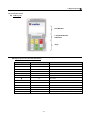
Cutes Corporation
。 READY
。 HZ
。A
。 ALARM
Displays forward/reverse/stop status
Operation instruction
keys
Control from keyboard
External control operation, stop
mode by set Cd04=1
FWD
REV
STOP
1
PROG
PROG
SET
READ
SET
1
STOP key
7
8
9
4
5
6
1
2
3
0
Step keys
1.
Stops inverter
operation
1.Stops
inverter
operation
2. Resets
function
2.Resets
function
3. Resets alarm indication
1. To change frequency
2. Select function items
3.Resets alarm indication
Function setting keys
These three keys offer selecting
read or setting value of function
24
.
4. Digital Operator■
Keyboard information
◆ LCD keypad
LCD Monitor
7-segment Monitor
Indicators
Keys
◆ Digital operator key function information
Key
Name
Function
FWD
Motor run
Motor run forward
REV
Motor run
Motor run reverse
STOP
Stop
PROG
Select function
Stop the revolution, reset
READ
Read
SET
Set and save
▲
Up
Increment
▼
Down
Decrement
Shift
Switch location of cursor
HZ
Frequency
A
Current
RDY
keypad status
ALM
Malfunction display
Switch input mode, set constants
Read/ quit constant
Input mode switch, constant setting
HZ LED means of recent revolution frequency
A LED means of recent revolution current
25
RDY LED means keypad working normally
ALM LED means malfunction occurred
4. Digital Operator■
◆ All mode operation
The operation mode of inverter equip monitoring and input modes, this section describes mode and
switch between modes.
A. Setting mode selection
Frequency is shown on the monitor after
inputpower, READY and HZ indicator lit.
READY
HZ
A
ALAR
M
↓ Press PROG key
READY
下
Monitoring item is Cd-00。
Press ▲▼ keys to select user’s setting.
A
↓ Press PROG key
READY
HZ
Monitoring item is CE-00。
Press ▲▼ keys to select user’s setting.
A
ALAR
M
↓ Press PROG key
READY
HZ
Back to monitoring (HZ)
A
ALAR
M
B. Modify monitoring item
READY
HZ
DISP indicator lit means monitoring item.
Operation command is shown when stop
operation. (HZ LED lit when display is
frequency)
A
ALARM
↓ Press PROG key
READY
HZ
Monitoring item is Cd-00。
Press ▲▼ keys to select user’s setting.
A
ALARM
26
4. Digital Operator■
↓ Please use ▲、▼、 or numeric keys to change figures
READY
HZ
Monitoring item is Cd-02。
Press ▲▼ keys to select monitoring
item.
A
ALARM
↓ Press READ key
READY
HZ
Enter Cd-02 monitoring item.
Factory value is operation frequency.
A
ALARM
↓Please use ▲、▼、 or numeric keys to change figures
READY
HZ
Enter Cd-02 monitoring item.
Modify constant is load current.
A
ALARM
↓ Press SET key
READY
HZ
Set constant, indicate ”PASS”。
Twinkle twice
(Indicate ”Err”if set wrong)
A
ALARM
READY
HZ
A
ALARM
Back to Cd-02
↓ Press PROG key
READY
HZ
A
ALARM
Monitoring item is CE-00
↓ Press PROG key
READY
HZ
Monitoring item isload current
(No load is A 0.0)
A
ALARM
27
4. Digital Operator■
C. Inspect malfunction record and monitoring value
↓ Press READ key
READY
HZ
Monitoring item is d1-00。
Press ▲、▼、 key to modify figure.
A
ALARM
↓Please use ▲、▼、 or numeric keys
to change figures
READY
HZ
Monitoring item is malfunction record is
d1-29.
(Please refer to the monitoring chart)
A
ALARM
↓ Press READ key
READY
HZ
A
ALARM
Malfunction record is nOEr means no
record.
OC means over current.
READY
HZ
A
ALARM
D. Press FWD/ REV key under any status
READY
HZ
Monitoring item is (HZ).
Frequency command is shown
when stop run.
A
ALARM
↓ Press FWD key
READY
HZ
A
ALARM
FWD
REV
Press FWD/REV key and enter
monitoring mode, monitoring mode is set
by Cd-02.
(FWD/REV indicator lit)
STOP
28
4. Digital Operator■
↓ Press PROG key
READY
HZ
Enter input mode. Press ▲、▼ key or
numeric keys to select constant, press
key to shift the cursor.
Select it to modify operation frequency.
A
ALARM
↓ Press READ key
READY
HZ
Enter input mode. Press ▲、▼ key or
numeric keys to select constant.
A
ALARM
↓Please use ▲、▼、 or numeric keys to change figures
READY
HZ
Enter input mode. Press ▲、▼ key or
numeric keys to select constant.
Modify the frequency is 20.00HZ。
A
ALARM
↓ Press SET key
READY
HZ
Set constant, indicate ”PASS”.
Twinkle twice
(Indicate ”Err”if set wrong)
A
ALARM
READY
HZ
A
ALARM
Back to Cd-00
↓ Press PROG key
READY
HZ
A
ALARM
Monitoring item is CE-00
↓ Press PROG key
READY
HZ
The inverter output frequency is modified
to be 20.00HZ.
A
ALARM
29
4. Digital Operator■
◆ LCD keypad Copy *
Press PROG+► Turn on Copy function then press once again to conceal
Memory 1
Memory 2
Memory 3
All Cd
All CE
All Cd &CE
A1-00
A2-04
A3-00
⌇
⌇
⌇
A1-99
A2-99
A3-99
CE
A4-04
⌇
A4-99
Memory allocation diagram
Constant information:
Code
Initial Factory
Function
Detail of Data
No.
Setting
0: Standard mode
1: Reserved
2: Modify Cd and CE on Keypad
3: Copy Cd from Control PCB to Memory 1 of Keypad
4: Copy CE from Control PCB to Memory 2 of Keypad
CC-00 Copy mode
5: Copy Cd & CE from Control PCB to Memory 3 of Keypad
6: Write Cd (Memory 1) to Control PCB
7: Write CE (Memory 2) to Control PCB
8: Write Cd & CE (Memory 3) to Control PCB
※LCD keypad Copy under development
30
0
4. Digital Operator■
◆ LCD keypad copy operation information
CC-00=0 : Standard Mode
CC-00=2 : Modify Cd & CE on keypad
Press SET to save
CC-00 See CC-00 only
Press PROG
A1-00A1-00 ~ A1-99, function code Cd
Press SET
(Memory 1)
Press PROG
A2-00A2-00 ~ A2-99, function code CE
Press SET
(Memory 2)
Press PROG
A3-00A3-00~A3-99, function code Cd of Cd & CE
Press SET
(Memory 3)
Press PROG
A4-00A4-00 ~ A4-99, function code CE of Cd & CE
Press SET
(Memory 3)
Press PROG
Press PROG+► No function
CC-00=0 or press STOP , return to standard Mode
31
5. User constants■
Index
Motor autotuning
-------------
P47
Motor autotuning
Function setting
-------------
P49
Frequency setting
P51
Frequency command selection
P52
Operation command selection
P52
Acceleraion/ deceleration time
P53
Stop method
P54
Jump frequency
P54
Start frequency
P55
DC break
P56
Multi-functional analog input
P57
Analog output setting
P58
Multi-functional terminal setting (DI terminal)
P59
Jog frequency
P60
Multi-speed frequency command
P62
Multi-functional relay setting
P64
V/F curve selecting
P67
Frequency command limit
P68
Torque boost, torque boost gain
P69
Motor rated current
Output/ input
------------terminals
V/F control
-------------
PID control
-------------
P70
PID control
Multi-step function
-------------
P74
The physical link
MODBUS
-------------
P79
Data structure in communication
Protections
-------------
P86
Preventing motor stalling function
P90
Motor search speed function
P92
Instantaneous current handling
P93
Overheating protection
P94
Dynamic brake
P95
Carrier wave frequency
P97
Data lock
P99
Setting LCD keypad functions
P101
Recovering factory settings
Environment setting
-------------
32
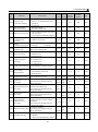
6. Constant tables ■
Code
No.
Cd-00
Function
Setting
frequency
Selecting
Cd-01 frequency
command
Operation
Cd-02 display
Cd-03
Torque mode
Description
Input master speed frequency by keyboard
( frequency command 1)
0:Digital input by key board
1:Analog input
2:Analog input (lag)
3:Multi-step function
4:DI UP/DOMN(2)
5:Pulse input(*)
6:Keypad UP/DOMN (1)
7:Keypad UP/DOMN (2)
8:Set frequency by terminal VR (E2 only)
0:Output frequency (contain slip boost)
1:Output current
2:RPM
3:DC BUS voltage
4:Output voltage
5:Module temperature
6:Power factor
7:Transient power (KW)
8:KWH
0:No auto boost
1:auto boost
Change
Setting Factory
during
value setting
operation
0.00~ 10.00
Yes
400.00 HZ
Modbus
Address
Page
128
P49
0~8
0
No
129
P51
0~8
0
Yes
130
P50
0~1
1
No
131
P68
0~3
0
No
132
P52
1~15
2
No
133
P64
Set V/F
Cd-05 pattern
0:Keyboard operation
1:External terminal (Keyboard stoppable)
2:MODBUS (Keyboard stoppable)
3:External terminal (Keyboard unstoppable)
1~14: Select from fixed 15 V/F mode.
15: Set by from Cd51to Cd58 V/F mode.
Motor rated
Cd-06 current
Set motor rated current as inverter current is 10.0~ 100.0
100%. Set torque boost gain as ratio.
100.0
%
No
134
P69
Torque boost
Cd-07 gain
Please adjust well when folling situation
occurred.
1:Increase this value when cable is too long. 0~2.50
2:Decrease this value when motor is vibrating.
0.3
Yes
135
P68
Acceleration
Cd-08 time 1
The time needed for set frequency
from 0 HZ to 50 HZ
0~
10.0
6000.0 sec
No
136
P52
Deceleration
Cd-09 time 1
The time needed for set frequency
from 50 HZ to 0 HZ
0~
10.0
6000.0 sec
No
137
P52
Acceleration
Cd-10 time 2
The time needed for set frequency
from 0 HZ to 50 HZ
0~
10.0
6000.0 sec
No
138
P52
Deceleration
Cd-11 time 2
The time needed for set frequency
from 50 HZ to 0 HZ
0~
10.0
6000.0 sec
No
139
P52
Operation
command
Cd-04
selecting
Cd-12
Frequency
command 2
2nd step frequency command
0~ 20.00
400.00 HZ
Yes
140
P60
Cd-13
Frequency
command 3
3rd step frequency command
0~ 30.00
400.00 HZ
Yes
141
P60
Cd-14
Frequency
command 4
4th step frequency command
0~ 40.00
400.00 HZ
Yes
142
P60
33
6. Constant tables ■
Code
No.
Function
Description
Cd-15 Jog frequency Fenquency when jog run
Cd-16 Start frequency Set motor start frequency
Upper limiter
of frequency
Lower limiter
Cd-18
of frequency
Acce./ dece. of
Cd-19
Joging
Cd-17
Set upper limiter of frequency command
Set lower limiter of frequency command
The time needed for set frequency
from 0 HZ to 50 HZ
Change
Setting Factory
during
value setting
operation
0~
5.00
Yes
60.00 HZ
0.5~
1.5
No
60.0
HZ
10.00~ 60.00
No
400.00 HZ
0.0~
0HZ
No
100.00
0.0~
1.0S
No
6000.0
0~
0HZ
Set the middle value of jump frequency, set 0 is 400.00
0~
Jump frequency invalid.
Cd-21 2
0HZ
400.00
Jump frequency
Cd-20 1
Cd-22
Jump
Set jump frequency width
frequency width
Start the DC break frequency as HZ when
decelerate to stop. Start frequency (Cd16) when
Cd23< start the DC break frequency (Cd16).
Set the inverter rated current as a percentage.
DC break
Set the DC break time when start. The setting
Cd-24
current
value is 0.00S, and the DC break is invalid when
start.
DC break time The setting value is 0.00S, and the DC break is
Cd-25
when start
invalid when start.
Cd-23
Cd-26
Cd-27
Cd-28
Cd-29
Cd-30
Cd-31
Cd-32
DC break
frequency
DC break time The setting value is 0.00S, and the DC break is
when stop
invalid when stop.
IN1 function
selecting
34
Page
143
P59
144
P54
145
P67
146
P67
147
P59
No
148
P54
No
149
P54
0~
20.0
1HZ
No
150
P54
0.0~
20.0
1HZ
No
512
P55
0~
100
50%
No
513
P55
0~
0.00
10.00
S
No
514
P55
0~
10.00
No
515
P55
No
155
P52
No
156
P90
Yes
157
P62
Yes
517
P56
Yes
518
P56
No
519
P56
0.00
S
Prohibited
0: Reverse
0~1
0.00
reverse selectin 1: Prohibited reverse
0: Invalid
Speed search
1: MCK feedback
function
0~3
0.00
2: Detected current +MCK feedback
selecting
3: MCK disconnection start + coast start
For replay,DOfunction selecting when operation 0~
TIME
5S
in timing
60000
Set filtered of analog input terminal time, noise
Analog input
1~
will be filtered, but input reaction will become
5
filter time
1000
slow.
Set percentage 100% when input 40mA to
0.0~ 100.0
IN1 input gain
correspond selecting function 100%
1000.0 %
4~20mA input mode, set IN1 function
0: De-active
1: Analog master speed
(1st speed, frequency command 1)
2: Adding master speed
(analog master speed auxiliary command)
3: Master speed gain
4: Auxiliary frequency 2
5: Auxiliary frequency 3
6: DC brake current
7: PID feedback value
8: PID command value
Modbus
Address
0~8
0
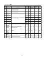
6. Constant tables ■
Code
No.
Function
Description
Cd-33 IN1 input bias Set percentage bias for 4mA when input
Set percentage when 10V input
Cd-34 IN3 input gain Set percentage 100% when set Cd35 correspond
Cd-35
Cd-36
Cd-37
Cd-38
selecting function 100%
0~10V input mode setting, set IN3 function
0: De-active
1: Analog master speed
(1st step speed, frequency command 1)
2: Adding master speed
IN3 function
(analog master speed auxiliary command)
3: Master speed gain
selecting
4: Auxiliary frequency 2
5: Auxiliary frequency 3
6: DC brake current
7: PID feedback value
8: PID command value
IN3 input bias Set ercentage bias when 0V input
Set ercentage bias when 0V input
IN2 input gain Set percentage 100% when set Cd38 correspond
selecting function 100%
0~10V input mode setting, set IN2 function
0: De-active
1: Analog master speed
( first step speed, frequency command 1)
2: Adding master speed
IN2 function
(Analog master speed auxiliary command)
3: Master speed gain
selecting
4: Auxiliary frequency 2
5: Auxiliary frequency 3
6: DC brake current
7: PID feedback value
8: PID command value
Cd-39 IN2 input bias Set ercentage bias when 0V input
Change
Setting Factory
during
value setting
operation
±100.0 0.00
Yes
Modbus
Address
Page
520
P56
Yes
521
P56
No
522
P56
±100.0 0.00
Yes
523
P56
0.0~ 100.0
1000.0 %
Yes
524
P56
No
525
P56
±100.0 0.00
Yes
526
P56
0.0~ 100.0
1000.0 %
0~8
0~8
0
1
Cd-40
Frequency
command 5
5th frequency command
0~ 45.00
400.00 HZ
Yes
168
P60
Cd-41
Frequency
command 6
6th
frequency command
0~ 50.00
400.00 HZ
Yes
169
P60
Cd-42
Frequency
command 7
7th
frequency command
0~ 55.00
400.00 HZ
Yes
170
P60
Cd-43
Frequency
command 8
8th
frequency command
0~ 60.00
400.00 HZ
Yes
171
P60
No
172
P53
0~
0.50
400.00 HZ
No
173
P62
0~
1.00
150.00
Yes
174
P94
Cd-44 Stop mode
Frequency
detect level
Speed
Cd-46 multiplier/
gears ratio
Cd-45
Set stop mode when send command
0: Deceleration stop
1: Free run stop
2: Free run stop, but restart after the
deceleration time is reached.
Set multifunction relay and DO frequency
active point
RPM is indicated on the screen
35
0~2
0
6. Constant tables ■
Code
No.
Function
Multifunction
relay 1
Cd-47
output function
selecting
Multifunction
relay 2
Cd-48
output function
selecting
DO output
Cd-49 function
selecting
Cd-50
Cd-51
Torque boost
delay time
Motor rated
voltage
Motor rated
frequency
Maximum
Cd-53 output
frequency
Maximum
Cd-54
voltage
Change
Setting Factory
during
value setting
operation
Description
0: Timer
(act when RUN time reach to Cd29 value)
1: Malfunction
2: Stopping
3: Acceleration
4: Speed agree
5: Deceleration
6: Frequency arrive
( operation frequency > Cd45 value)
7: Current arrive
(compares to Cd85and Cd86 value)
8: Overheat (Cd82) predict action
9: OL malfunction action
10: x
The torque boost delay time is set in ms units.
Set torque boost primary delay time constant.
Adjust in the following circumstance:
1. When the motor is oscillating, increase the
set values.
2. When the responsiveess of the motor is low,
decrease the set values.
Each factory value of each model
Cd-52
Cd-55
Middle output
frequency
Cd-56
Middle output
current
Cd-57
Minimum
output frequency
Minimum
output voltage
Unload current
Cd-59 adjusting
(FG only)
Torque bosst
Cd-60 frequency
(FG only)
1
No
175
P62
0~10
1
No
176
P62
0~10
8
No
177
P62
0~
50
10000 msec
No
X
P68
50.0~
500.0
By
spec.
No
527
P67
10.0~
400.0
60.0
HZ
No
528
P67
10.0~
400.0
60.0
HZ
No
529
P67
No
530
P67
No
531
P67
No
532
P67
No
533
P67
No
534
P67
0.0 ~
400.0
0.5
HZ
0.0 ~ By
500.0 spec.
Increase the values when unload current is
bigger, Decrease the values when it is lower.
Collocate Cd-60 to adjust.
Set torque boost operation frequency
Select fixed PWM frequency:
Selecting PWN 0: 2k 1: 3k 2: 3.5k 3: 4k 4: 5k 5: 6k
Cd-61
frequency
6: 7k 7: 8k 8~15: 4k
15: Set by Cd62 and Cd63
36
Page
0~10
10.0~ By
Set V/F curve, please adhere the following 500.0 spec.
rules:
0.0 ~ 3.0
Cd53≧Cd52>Cd55≧Cd57
400.0 HZ
Cd54≧Cd51>Cd56≧Cd58
0.0 ~ By
500.0 spec.
Cd-58
Modbus
Address
30~
150
60
%
No
X
P68
1.5~10
2.50
HZ
No
X
P68
0~15
2
No
189
P95
6. Constant tables ■
Code
No.
Function
Maximum
PWM
Cd-62
frequency
setting
Minimum
PWM
Cd-63
frequency
setting
Cd-64
Cd-65
Cd-66
Cd-67
Cd-68
Cd-69
Cd-70
Cd-71
Cd-72
Cd-73
Cd-74
Cd-75
Cd-76
Change
Setting Factory
during
value setting
operation
Description
Modbus
Address
Page
Settable PWM maximum frequency freely
(operation frequency will be higher)
2.0~8
6k
No
190
P95
Settable PWM minimum frequency freely
(operation frequency will be lower)
2.0~8
3k
No
191
P95
0~1
1
No
192
P94
0~40
20V
No
198
P94
00~
20.00
0.2S
No
193
P96
± 15.0
0V
No
195
P94
0~1
1
No
535
P86
30~
200
*
%
No
536
P86
30~
100
50
%
No
537
P87
0~1
1
No
538
P87
0~50
20
No
199
P87
0~1
1
No
539
P88
30~
200
*
%
No
540
P88
155~
500
By
spec.
No
541
P89
0~
200
120
%
No
542
P90
Set brake mode
Dynamic
0: operation wnen run
braking mode
1: no operation when speed is the same
Dynamic
braking
Set 20V equal to 350+20=370Vdc DB on
voltage
positioning
Instantinitial
Instantinitial field time when start motor.
field time
Fine tune
DC Bus
Adjust the standard score of DC Bus
standard score
Stall
preventive
0: Invalid
function in
1: Valid
accel.
Stall
Set rated current as 100% for stall preventive
preventive
leveling acceleration
level in accel.
Stall
In accordance with Cd70 setting value when
prevention
inverter operation is over motor rated
limit during
frequency to reduce stall prevention limit
accleration
during accleration
Stall
prevention
0: Invalid
limit during
1: Valid
deceleration
Over current
voltage active Over voltage protection function active point
point
Constant
speed stall
0: Invalid
prevention
1: Decelerate by deceleration time 2 (Cd11)
during
operation
Constant
speed stall
Set rated current as 100% for constant speed
preventive
stall preventive level
level during
operation
Input voltage
Set input voltage (RST)
active point
Speed search When Cd28=2 is valid (please reduce setting
active current value when unable to restart
* FG : 160%; FP : 125%
37
6. Constant tables ■
Code
No.
Function
Change
Setting Factory
during
value setting
operation
Description
Speed search
Cd-77 deceleration When Cd28=2 is valid
time
Speed search
Cd-78
When Cd28=2 is valid
waiting time
0: Invalid
1: Valid, restart when power recovered in time
Momentary
of (Cd80), detect low voltage of master
Cd-79 power loss
power when exceeded.
direction
2: Movement of CPU is valid, restart when
power recovered (Cd80 will not be
considered)
Momentary
power loss
Restart valid time limit when set Cd79=1
Cd-80
boost time
Output voltage From 0V to recover is time of maximum output
Cd-81
recover time voltage when set restart
Overheating
Set Cd84 as 100% for level of detecting
Cd-82 forecast
overheating forecast for inverter
detection level
Motion when 0: Deceleration stop
overheating 1: Coast stop
Cd-83
forecast
2: Emergency stop
detection
3: Continuous operation
Set ℃ as unit for detecting level of inverter
Temperature
overheating
Cd-84 protection
Software protection is invalid when set 100℃
level
(OH is only hardare protection)
Set hysteresis range when relay
Current
(Cd47、Cd48)and DO (Cd49)
Cd-85 hysteresis
range
current detected
Current detect
Cd-86
Set current detect level when current detected
level
Set filter time of analog output termainal to
Analog output
Cd-87
eliminate the noise in effect.
filter time
Input reaction will become slow.
Analog output Set voltage bias value of operation frequency
Cd-88 1
analog output, 10V is 100%。
(FM) bias
Analog output
Set voltage amplify magnification of operation
Cd-89 1
frequency analog output
(FM) gain
Analog output
Set voltage bias value of operation current
Cd-90 2
analog output, 10V is 100%
(AM) bias
Analog output
Set voltage amplify magnification of operation
Cd-91 2
frequency analog output
(FM) gain
38
Modbus
Address
Page
0.1~
10.0
2.0S
No
543
P90
0.0~
20.0
0.2S
No
544
P90
0~2
0
No
545
P92
0~2.0
0.1S
No
546
P92
0.1~
20.0
3S
No
547
P92
50~
100
90%
No
548
P93
0~3
3
No
549
P93
20~
100
85℃
No
550
P93
2~20
2%
Yes
551
P63
30~
150
100
%
Yes
552
P63
50~
1000
100
ms
Yes
553
P57
±10.0 0.0%
Yes
554
P57
0.00
~2.50
1.00
Yes
555
P57
±10.0% 0.0%
Yes
556
P57
0.00
1.00
~2.50
Yes
557
P57
6. Constant tables ■
Code
No.
Function
Change
Setting Factory
during
value setting
operation
Description
Multifunction
Cd-9
terminal S1
2
function
Multifunction
Cd-93 terminal S2
function
Multifunction
Cd-94 terminal S3
function
Multifunction
Cd-95 terminal S4
function
Multifunction
Cd-96 terminal S5
function
0: 3-wire operation control
1: Multi-step speed 1
2: Multi-step speed 2
3: Multi-step speed 3
4: Reserved
5: JOG frequency
6: Forward JOG
7: Reverse JOG
8: Auto restart attempts
9: Multi-steps acceleration time
10: Multi-steps deceleration time
11: PID control disable
12: PID integration control reset
13: PID integration control maintain
14: PIDsoft start
15: Switch PID error input characteristics
16: Not used
Multifunction 17: PLC reset
18: Emergency stop
Cd-97 terminal S6
19: Coast stop
function
20: Electrical adjustable speed UP
21: Electrical adjustable speed Down
0: Lock data (read only)
Cd-98 Lock data
1: Data is variable (simple)
2: Data is variable
0: invalid
1: Only recover PLC constant
2: Recovering Factory value, uncontain PLC
constant
Cd-99 Initialize data
3: Recovering Factory value, uncontain motor
and PLC constant
4: All constants recover factory value
5: Eliminate malfunction record
39
Modbus
Address
Page
0~21
9
No
558
P58
0~21
10
No
559
P58
0~21
2
No
560
P58
0~21
8
No
561
P58
0~21
1
No
562
P58
0~21
19
No
563
P58
0~2
2
Yes
564
P97
0~5
0
No
565
P101
6. Constant tables ■
Code
No.
Function
Slip boost
CE-00 gain (FG
only)
Slip boost
CE-01 delay time
(FG only)
Slip boost
CE-02 limit (FG
only)
Electrical
adjustable
CE-03 speed
Stop restart
attempts
Password
CE-04
input
1st step
CE-05 speed
setting
2nd step
CE-06 speed
setting
3rd step
CE-07 speed
setting
4th step
CE-08 speed
setting
5th step
CE-09 speed
setting
6th step
CE-10 speed
setting
7th step
CE-11 speed
setting
8th step
CE-12 speed
setting
9th step
CE-13 speed
setting
10th step
CE-14 speed
setting
11th step
CE-15 speed
setting
Change
Setting Factory
during
value setting
operation
Description
To upgrade the speed accuracy when drive to
load
Adjust this constant at the following times
1. Increase setting value when speed is lower 0~2.50 0
than target value
2. Decrease setting value when speed is
higher than target value
Slip boost primary delay time is set in ms unit
Adjust this constant at the following times
0~
500
1. Reduce the setting when slip boost
responsive is slow
10000
ms
2. When speed is not stabilized, increase the
setting
Modbus
Address
Page
Yes
X
P69
No
X
P69
0~250
200
%
No
X
P69
0~1
0
No
X
P50
Set user password
0~
9999
0
No
X
P97
Multi-step function control 1st step speed
setting
0~
0 HZ
400.00
Yes
233
P74
Multi-step function control 2nd step speed
setting
0~
0 HZ
400.00
Yes
234
P74
Multi-step function control 3rd step speed
setting
0~
0 HZ
400.00
Yes
235
P74
Multi-step function control 4th step speed
setting
0~
0 HZ
400.00
Yes
236
P74
Multi-step function control 5th step speed
setting
0~
0 HZ
400.00
Yes
237
P74
Multi-step function control 6th step speed
setting
0~
0 HZ
400.00
Yes
238
P74
Multi-step function control 7th step speed
setting
0~
0 HZ
400.00
Yes
239
P74
Multi-step function control 8th step speed
setting
0~
0 HZ
400.00
Yes
240
P74
Multi-step function control 9th step speed
setting
0~
0 HZ
400.00
Yes
241
P74
Multi-step function control 10th step speed
setting
0~
0 HZ
400.00
Yes
242
P74
Multi-step function control 11th step speed
setting
0~
0 HZ
400.00
Yes
243
P74
Set maximum limit value of slip boost
Set motor rated slip is 100%。
0: Self-protection setting value
1: (Cd18) frequency minimum limit value is
recovered under stop status
40
6. Constant tables ■
12th step
speed setting
Multi-step function control 12th step speed
setting
Change
Setting Factory
during
value setting
operation
0~
0 HZ
Yes
400.00
13th step
speed setting
14th step
CE-18
speed setting
15th step
CE-19
speed setting
16th step
CE-20
speed setting
Multi-step function control 13th step speed
setting
Multi-step function control 14th step speed
setting
Multi-step function control 15th step speed
setting
Multi-step function control 16th step speed
setting
0~
400.00
0~
400.00
0~
400.00
0~
400.00
Code
No.
CE-16
Function
CE-17
Description
Modbus
Address
Page
244
P74
0 HZ
Yes
245
P74
0 HZ
Yes
246
P74
0 HZ
Yes
247
P74
0 HZ
Yes
248
P74
CE-21
1st step time
setting
Multi-step function control 1st step time
setting
0~255
0
No
249
P75
CE-22
2nd step time
setting
Multi-step function control 2nd step time
setting
0~255
0
No
250
P75
CE-23
3rd step time
setting
Multi-step function control 3rd step time
setting
0~255
0
No
251
P75
CE-24
4th step time
setting
Multi-step function control 4th step time
setting
0~255
0
No
252
P75
CE-25
5th step time
setting
Multi-step function control 5th step time
setting
0~255
0
No
253
P75
CE-26
6th step time
setting
Multi-step function control 6th step time
setting
0~255
0
No
254
P75
CE-27
7th step time
setting
Multi-step function control 7th step time
setting
0~255
0
No
255
P75
CE-28
8th step time
setting
Multi-step function control 8th step time
setting
0~255
0
No
256
P75
CE-29
9th step time
setting
Multi-step function control 9th step time
setting
0~255
0
No
257
P75
CE-30
10th step time Multi-step function control 10th step time
setting
setting
0~255
0
No
258
P75
CE-31
11th step time
setting
Multi-step function control 11th step time
setting
0~255
0
No
259
P75
CE-32
12th step
time setting
Multi-step function control 12th step time
setting
0~255
0
No
260
P75
CE-33
13th step
time setting
Multi-step function control 13th step time
setting
0~255
0
No
261
P75
CE-34
14th step
time setting
Multi-step function control 14th step time
setting
0~255
0
No
262
P75
CE-35
15th step
time setting
Multi-step function control 15th step time
setting
0~255
0
No
263
P75
CE-36
16th step
time setting
Multi-step function control 16th step time
setting
0~255
0
No
264
P75
CE
Reserved
37-46
41
6. Constant tables ■
Code
No.
Function
Multi-step
function
mode
CE-47
(continuous
operation)
selecting
Multi-step
CE-48 function
mode reset
CE
Reserved
49-53
Change
Setting Factory
during
value setting
operation
Description
0~6
0
No
275
P76
Reset procedure and time to zero
0~1
0
Yes
276
P76
0~4
0
No
282
P71
0~25
1.0
Yes
283
P72
0~360 1.0
Yes
284
P72
Set maximum value of integral time, set
maximum frequency as 100%
0~100 100
Yes
285
P72
Set derivative time of D control
0~10
Yes
286
P72
Set limit value of PID output, set
maximum frequency as 100%
0~100 100
Yes
287
P72
Adjust offset of PID output
±100
0
Yes
288
P72
Set low-pass filter time of PID output
0~10
0
Yes
289
P72
PID output forward/ reverse characteristics
0: Normal
1: Inverting
0~1
0
No
290
P72
No
291
P72
No
292
P72
No
293
P73
CE-54
Select PID
control
CE-55
Proportional
control ( P )
Set ratio gain of
CE-57
CE-58
CE-59
CE-60
CE-61
Integral time
(I)
Maximum
value of
Integral
control ( I )
Derivative
time (D)
Maximum
value of PID
output
PID offset
adjust
PID output
delay time
PID output
CE-62 characteristics
selecting
CE-63
PID output
gain
Page
Select liner or gradually operation method
0: invalid
1: PID output is inverter output, D control
error
2: PID output is inverter output, D control
feedback
3: PID output is adjustment of inverter
output, D control error
4: PID output is adjustment of inverter
output, D control feedback
CE-56
Modbus
Address
P control
Set integral time of
I control
Set amplify magnification of PID output
0
0.0~25.0 1.0
PID output
CE-64 reverse
selecting
0: Limit output is 0 when PID output is
negative
1: PID output is negative when reverse,
output is 0 when set Cd27= 1
PID
command
CE-65 acceleration/
deceleration
time
Set PID command acceleration/
deceleration time, setting value is the time 0.0~25.5 0.0
that accelerates from 0 to 100%
42
0~1
0
6. Constant tables ■
Code
No.
Function
CE-66
Position of P
controller selecting
CE-67
PID output delay
position selecting
CE-68 Select I control reset
Serial
CE-70 communication
position
Serial
CE-71
communicationspeed
Change
Setting Factory
during
value setting
operation
Description
0: P control independence
1: Enter I、D controller after error
passed by
P controller
0: PID output delay
1: D control output delay
Page
0~1
0
No
294
P73
0~1
0
No
295
P73
0~1
0
No
296
P73
0~240
1
Yes
209
P80
0~3
3
No
210
P80
2~65
2mS
No
211
P81
0~2
0
No
213
P81
0~2
0
No
X
P99
Set LCD display contents function
0~3
0
No
X
P99
X P91
P89
0: Clear I control integral value when
stop operation
1: Use terminal to eliminate integral
Set address of inverter
0: 1200 bps
2: 4800 bps
1: 2400 bps
3: 9600 bps
Serial communication Set the time of inverter from received
feedback time
data to start replying data
0: Invalid
CE-74 Parity bit Check
1: Odd Parity bit
2: Even Parity bit
Select LCD display method
0: 2 combinations
LCD permutation
CE-75
selecting
1: 4 combinations
2: 8 combinations
CE-72
CE-76 LCD group selecting
Modbus
Address
CE-80
Low voltage
demonstration
0: maintains the LU-B demonstration
1: Not maintains the LU-B
demonstration
0~1
1
不可
CE-81
IN1 transform
magnification value
Screen indicates kg value
0.0~
50.0
10.0
No
X
P100
CE-82
Motor slip
(FG only)
0.00 ~ 2.00
20.00 HZ
No
X
P97
10.0 ~ 30.0
100.0
%
No
X
P97
4
pole
No
X
P97
0
%
No
X
P97
No
X
P97
No
X
P97
CE-83
CE-84
CE-85
CE-86
Set motor rated slip
This constant is automatically set
during autotuning
Set inverter rated current as 100%
Motor Noload current and motor Noloadcurrent
(FG only)
This constant is automatically set
during autotuning
Set motor pole
Motor pole
This constant is automatically set
(FG only)
during autotuning
Set motor rated as 100% and the
Motor leakage
voltage drop due to motor leakage
inductance (L.S)
inductance
(FG only)
This constant is automatically set
during autotuning
Set motor resistance
Motor resistance (RS) This constant is automatically set
during autotuning
CE-87 Loading selecting
0: 150% overload (heavy duty
model)
1: 120% overload (light duty model)
43
2~8
0.0~
40.0
0.000
By
~
spec.
65.000
0~1
1
6. Constant tables ■
Code
No.
Function
Change
Setting Factory
during
value setting
operation
Description
0 : Rotational mode
1 : UnRotational mode 1
2 : UnRotational mode 2
Set percentage of automatic adjust V/F
curve low speed boost
CE-88
AUTOTUN
E mode
CE-89
V/F boost
setting
CE-90
Motor rated
voltage
0.0 ~
500.0
CE-91
Motor rated
current
CE-92
Motor rated
frequency
Modbus
Address.
Page
0~2
2
No
X
P47
0~100
45%
No
X
P47
By
spec.
No
X
P47
10.0 ~
100%
200.0
No
X
P47
0.0 ~
400.0
By
spec.
No
X
P47
CE-93 Motor pole
2~8
4
No
X
P47
Motor rated
RPM
Motor
CE-95 Noload
current
Restore
initialize
CE-96
value of
motor voltage
Restore
initialize
CE-97 value of
motor
frequency
0~
1750
7200
No
X
P47
Collocate unrotational mode adjustsetting
10~
100
45%
No
X
P47
0: 380V 1: 415V 2: 440V 3: 460V
(except 220V series)
0~3
0
No
X
P89
0: 50HZ
1: 60HZ (220V series is fixed 60HZ)
0~1
0
No
X
P89
0
不可
X
P97
By
spec.
No
X
X
Proccess autotunning by motor nameplate to
set all constants of motor
CE-94
User pass
CE-98
0~
For Cd-98 Lock data
word
CE-99 HP setting
9999
Set by specification of inverter
0~63
44
6. Constant tables ■
Monitoring status
Code
No.
Function
Modbus
Address.
d1-01
Output frequency (contain slip boost)
64
d1-02
Output current
65
d1-03
Frequency command
66
d1-04
DC BUS voltage
67
d1-05
Output voltage
68
d1-06
DI terminal status
69
d1-07
Module temperature
70
d1-08
RUN status
71
d1-09
RUN command
72
d1-10
Malfunction status
73
d1-14
Power factor
74
d1-15
Transient power (KW)
75
d1-16
KWH
76
77~80
d1-14~17 Reserved
d1-18
IN1(0~20mA)
81
d1-19
IN2(0~10V)
82
d1-20
IN3(0~10V)
83
d1-21
PID command value
84
d1-22
PID feedback value
85
d1-23
PID output value
86
d1-24
PID frequency command modulus
87
d1-25
DSP firmware version
88
d1-26
Interface chip firmward version
89
d1-27
Option card firmware version
90
45
6. Constant tables ■
Monitoring status
Code
No.
Function
Modbus
Address.
d1-28
Inverter rated current
91
d1-29
Malfunction record 1
92
d1-30
Malfunction record 2
93
d1-31
Malfunction record 3
94
d1-32
Malfunction record 4
95
d1-33
MCK
96
d1-34
RPM ( co-operate Cd46 )
97
d1-35
Pressure value (Kg) (IN1 input)
98
d1-36
Reserved
99
d1-37
Days of operation
97
d1-38
Hours and minutes of operation
101
d1-39
Micro-seconds of operation
102
d1-40
Record breakdown number of times
103
◆Malfunction record
Description: Record malfunction causes to eliminate malfunction situation.
1. Malfunction of Err、Ero、Erc etc. will not be recorded. (P102~103)
2. Memorize the latest four records.
3. Low voltage malfunction will not be recorded when inverter stand by.
4. d1-29~32 only can be read or deleted all by Cd99, useer is unable input malfunction record.
46
7. Motor autotuning ■
◆Autotuning constant
Code
No.
Function
Setting
value
Factory
setting
Change during
operation
CE-88
AUTOTUNE mode
0~2
2
X
CE-89
V/F boost setting
0~100
45%
X
CE-90
Motor rated voltage
0.0~500.0
By specification
X
CE-91
Motor rated current
10.0~200.0
100.0%
X
CE-92
Motor rated frequency
0.0~400.0
By specification
X
CE-93
The pole of motor
2~8
4pole
X
CE-94
Motor rated RPM
0~7200
1750rpm
X
CE-95
Motor unload current
10~100
45%
X
Description: Please input CE88~ CE95 constants to proceed motor constant autotuning according to
specification of nameplate.
The low speed compensation of V/f curve were set by CE89 to apply to Rotational autotuning (CE88=0), V/f
curve will be modified after autotuning. Constant setting is the percentage of low speed star torque.
Select adjustment mode
1. Rotational mode autotuning (CE88=0)
Input specification of nameplate after set CE88=0. When the page of CE-88 constants were operated. The
function of autotuning will be processed by pressing FWD this moment, TunE is shown on screen. Motor
data is needed by autotuning when motor run.
2. Stationary mode autotuning (CE-88=1)
Input specification of nameplate after set CE-88=1. When the page of CE-88 constants were operated.
The function of autotuning will be processed by pressing FWD this moment, TunE is shown on screen.
Motor data is needed by autotuning when motor run. (Collocate with CE-95 motor unload current
setting)
3. Stationary autotuning for line-to-line resistance only (CE-88=2)
Autotuuning can beused to prevent controle errors when the motor cable is long or the cable length has
changed or when the motor and inverter have different capacities. When keypad is operated through the
page of CE-88 constants, press FWD to process autotuning decetion motor line-to-line resistor (Cd-78).
Notice: 1. The motor have to be disconnected from machine and a danger never occurs when Rotational mode
autotuning is implemented.
2. A machine does not allow motor spontaneously Rotational, please implement Stationary mode
autotuning. (CE-88=1)
3. Power will be supplied to the motor when Stationary mode autotuning and stationary for line-to-line
resistance are performed even though the motor will not turn. Do not touch the motor until autotuning
has been completed.
47
7. Motor autotuning■
Code
No.
Cd-55
Middle output voltage
Cd-58
Minimum output vlotage
CE-82
Motor slip
CE-83
Motor unload current
CE-84
The pole of motor
CE-85
Motor leakage inductance
CE-86
Motor resistance
Function
Description: Constants Cd55, Cd58, CE82, CE83, CE84, CE85, CE86 will be changed automatically after process
motor autotuning.
※ Proccess motor constant autotuning under CE-88 (AUTOTUNE mode).
48
8. Constant setting by function ■
◆Frequency setting
Code
No.
Function
Setting
value
Factory
setting
Change during
operation
Cd00
Frequency setting
0~400.00HZ
10.00
0
Description: There are 5 methods to change set frequency. Items A~C are methods of panel key operation, items D-E
are methods of external terminal input.
A. Keypad VR (Cd01=08) Only E2
B. Use PROG key to input data (Cd01=0)
C. Use ▼、▲ key to input data (Cd01=6、7)
D. Use Multi-Step function to setting (Refer to function CE05 to CE55.)
E. Set external voltage (IN2、IN3)
F. Set external current (IN1)
Notice: Set value should be in accordance with V/F slope (Cd05) and upper limit frequency (Cd17).
Set by function key
A. At display function, press READ and setting (Cd01=0)
F
1
0.
0
0
C
d
-
0
0
READ
1
0.
0
0
▲▼
3
0.
0
0
SET
3
0.
0
0
C
d
-
0
0
C
E
-
0
0
3
0.
0
0
PROG
PROG
PROG
49
8. Constant setting by function■
B. Use PROG key to input data (Cd01=0)
F
Numeric
1
0.
0
0
3
0.
0
0
3
0
0
0
3
0
0
0
key
SET
F
Note:
Indicate 7 Segment LED twinkle.
◆Monitor display
Code
No.
Function
Setting
value
Factory
setting
Change during
operation
Cd02
Monitor display
0~8
0
0
Setting
value
Factory
setting
Change during
operation
0~1
0
X
Description: Monitoring setting when set operation.
0:Output frequency (contain slip boost)
1:Output current
2:RPM
3:DC BUS voltage
4:Output voltage
5:Module temperature
6:Power factor
7:Transient power (KW)
8:KWH
◆Operation display
Code
No.
CE03
Function
Electrical adjustable speed
Stop restart attempts
Description: set Cd01=4 or 7 to select stop if reset or not.
CE03=0 : No reset electrical adjustable speed when stop to keep setting speed.
CE03=1 : Reset electrical adjustable speed to 0 when stop.
50
8. Constant setting by function■
◆Frequency command selecting
Code
No.
Function
Cd01
Selecting frequency
command
Setting
value
Factory
setting
Change during
operation
0~8
0
X
Description: Constant Cd01 is input way selecting of frequency, selectable items as following:
0: Digital input by key board
1: Analog input
2: Analog input (lag)
3: Multi-step function 1
4: DI UP/DOMN(2)
5: Pulse input (option) *
6: Keypad UP/ DOMN (1)
7: Keypad UP/ DOMN (2)
8: Set frequency by terminal VR (E2 only)
■ Use keypad to input frequency command
Input frequency command by keypad after set Cd01=0. Use constant Cd00 to input frequency commad when ordinary
operation.
■ Use voltage (current) to input frequency command (analog input IN1~IN3, option cardAI1~2)
Input frequency command by analog input after set Cd01=1.
Input frequency command (contained lag) by analog input after set Cd01=2.
■ Input frequency command by multi-step function to set multi-step function
Set Cd01=3 to execute multi-step function. 16 steps are settable and set each step command by CE05~CE36.
(Please refer to page P74)
■ DI
UP/ DOMN
Set DI terminal to execute frequency UP/ DOMN by Cd92~Cd97 after set Cd01= 4.
Set acceleration/ deceleration by Cd10.
(Please refer to page P58)
■ Pulse input (option card is underdevelopment)
Use pulse input terminal of option card to input pulse as frequency after set Cd01=5.
■ Keypad UP/DOMN
Set frequency by ▲、▼ UP/ DOMN of keypad after set Cd01= 6
Set acceleration/ deceleration by Cd10.
■ Keypad UP/DOMN
Set frequency by ▲、▼ UP/ DOMN of keypad and DI terminal after set Cd01= 7.
Set acceleration/ deceleration by Cd10.
■ Set frequency by terminal VR
Set frequency by terminal VR after set Cd01=8. (E2 only)
51
8. Constant setting by function ■
◆Operation command selecting
Code
No.
Function
Setting
value
Factory
setting
Change during
operation
Cd04
Operation command setting
0~3
0
X
Cd27
Prohibited reverse selecting
0~1
0
X
Description: Cd04=0: keypad control :
Use FWD、REV、STOP key of keypad to execute inverter operation.
Cd04=1: External terminal control (stoppable by keypad) :
Use operation control terminal to execute inverter operation. Stoppable by keypad (STOP).
Cd04=2: MODBUS communication :
Use MODBUS communication to execute operation. (page 74)
Cd04=3: External termonal control (No keypad stop) :
Use operation control terminal to execute operation. No keypad stop (STOP)。
Cd27=0 to execute reverse by keypad (REV)。
Cd27=1 unable to execute reverse by keypad (REV)
Notice : CD27 prohibits reverse selecting, only restricts keypad control.
◆Acceleration/ deceleration
Code
No.
Function
Setting
value
Factory
setting
Change during
operation
Cd08
Acceleration 1
0.0~6000.0
10.0
O
Cd09
Deceleration 1
0.0~6000.0
10.0
O
Cd10
Acceleration 2
0.0~6000.0
10.0
O
Cd11
Deceleration 2
0.0~6000.0
10.0
O
Description: Set frequency by the time is needed from 0 HZ to 50 HZ.
T1:time for acceleration/ deceleration
△F:Frequency change
For example: Frequency reduce from 50 HZ to 30 HZ, time 1 sec.
52
8. Constant setting by function ■
◆Stop method selecting
Code
No.
Function
Setting
value
Factory
setting
Change during
operation
Cd44
Stop method selecting
0~2
0
X
Description:
Cd44= 0: Deceleration stop
Set the motor to decelerate to stop according to selecting time after set Cd44= 0, (factory setting: Cd09 deceleration
time 1). If DC braking were set when stop, DC braking is proceed when output frequency is
lower than Cd23
Run command ON
OFF
Output frquency
DC injection brake
Decelerates to stop
at deceleration time
DC injection brake time when stopping
CD26
Cd44=1: coast stop
If the stop command is input when set Cd44=1, the inverter output voltage is interrupted, the motor coasts to
inertia the load.
Run command
stop at
ON
OFF
Decelerates to stop
at deceleration time
Cd44=2: Coast stop, but restart after the deceleration time is reached.
If the stop command is input when Cd44=2, the inverter output is interrupted to coast the motor to stop. the motor
coasts to stop at inertia the load. Run commands are ignored until the time has elapsed. Set timer time by
Cd10(acceleration time 2).
Run command ON
ON
OFF
ON
OFF
Lgnore run command
Decelerates to stop
at deceleration time
According to select frequency when
decelerated time and stop to proceed time
53
8. Constant setting by function ■
◆Jump frequency
Code
No.
Function
Setting
value
Factory
setting
Change during
operation
Cd20
Jump frequency 1
0.00~400.0
0
X
Cd21
Jump frequency 2
0.00~400.0
0
X
Cd22
Jump frequency width
0.0~20.0
1
X
Description:The objective of this function in order to avoid resonance occurred between subsistent vibration of
machine and motor operation. Set machine vibration frequencythat you would like to avoid. Motor operation will be
prohibited by jump frequency setting when constant speed operation, but jump will not occur during accleration/
deceleration procedure.
Output frequency
When frequency command declines
輸出頻率
Jump frequency width
Cd22
Jump frequency
Jump frequency 1
Jump frequency 2
◆Start frequency
Code
No.
Function
Setting
value
Factory
setting
Change during
operation
Cd16
Start frequency
0.5~60.00
1.5HZ
X
Description: Set motor start frequency, settable range of frequency from 0.5HZ to 30HZ, accuracy is 0.01HZ
54
8. Constant setting by function ■
frequency
Start frequency
Time
※Notice: The most appropriate for start frequency is from 0.5HZ to 10HZ
◆DC break
Code
No.
Function
Setting
value
Factory
setting
Change during
operation
Cd23
DC break frequency
0.0~20.0
1.0HZ
X
Cd24
DC break current
0~100
50%
X
Cd25
DC break time when start
0.0~10.0
0.0sec
X
Cd26
DC break time when stop
0.0~10.0
0.0sec
X
Description: Set DC injection brake when start to the motor while it is coasting to stop, to stop the motor and then
restart it.
Cd23: Set DC break function when stop. Stop method setting is deceleration stop or all range DC stop, output frequency
is smaller than Cd23 and start DC break after input stop operation command.
Cd24: Set DC break current as inverter rated current.
Cd25: Set to 0 to disable the DC injection brake at start.
Cd26: Set to 0 to disable the DC injection brake at stop.
※If setting value of Cd23 less then minimum input frequency, to proceed DC injection brake as minimum output
frequency Cd57.
※Set multi-step analog input (Cd32/Cd35 / Cd38 )= 6, use analog input as DC break current command, 100% inverter
rated current when input 10V ( 20mA ).
55
9. Output/ input terminals■
◆Multi-functions analog input
Code
No.
Function
Setting
value
Factory
setting
Change during
operation
Cd30
Analog input filter time
1~1000
5
O
Cd31
IN1 input gain
0.0 ~
1000.0
100.0%
O
Cd32
IN1 functions selecting
0~8
0
X
Cd33
IN1 input bias
±100.0
0.0%
O
Cd34
IN3 input gain
0.0 ~
1000.0
100.0%
O
Cd35
IN3 functions selecting
0~8
0
X
Cd36
IN3 input bias
±100.0
0.0%
O
Cd37
IN2 input gain
0.0 ~
1000.0
100.0%
O
Cd38
IN2 functions selecting
0~8
1
X
Cd39
IN2 input bias
±100.0
0.0%
O
Description: Set filter time by Cd30. Set filter time longer. The ability of reject noise is stronger. But reactionof input
will be corresponsive slower. Please set suitable time by request.
Terminals of IN1 ( 4~20mA), IN2 (0~+10V) and IN3 (0~+10V) are multi-function analog input, the input specification
10V(20mA) indicates 100%, use Cd31, Cd34 and Cd37 to set enlarge/ reduce magnification, and Cd33、Cd36、Cd39 to
set bias %. Cd32、Cd35、Cd38. All functions of multi-function analog input, please refer to multi-function analog input
functions list.
Notice: Limits of authority level IN3>IN2>IN1
For example: Set Cd32(IN1) and Cd35(IN3)=1 at the same time, and IN1 will not operate when input IN1.
56
9. Output/ input terminals ■
◆Multi-functions analog input functions list
Code
No.
Function
0
De-active
1
Analog master speed (1st step spped)
2
Adding master speed
3
Master spped gain
Description
--Frequency command 1
Analog master speed auxiliarycommand
Analog master speed limit gain
nd
4
Auxiliary frequency 2 (2 step spped)
Frequency command 2
5
Auxiliary frequency 3 (3rd step spped)
Frequency command 3
6
DC braking current
Inverter rated current
7
PID feedback value
Feedback value source
8
PID command value
PID input value
◆Analog output setting
Code
No.
Function
Setting
value
Factory
setting
Change during
operation
50~1000
100
O
Cd87
Analog filter time
Cd88
Analog output 1(FM) bias
±10.0
0.0%
O
Cd89
Analog output 1(FM) gain
0.00 ~2.50
1.00
O
Cd90
Analog output 2(AM) bias
±10.0
0.0%
O
Cd91
Analog output 2(AM) gain
0.00 ~2.50
1.00
O
Description: Multi-function analog output can be selected monitoring (d1-xx) to transfer to analog voltage output,
when selected one is 100%, output 10V. Please refer to d1 constants, page 38.
The function of Cd87 could be set as the filter time of VOUT. The filter time setting is longer, the capability of reject
fiter is stronger, but the reaction of input become slow. Please set the adaptable time by user request.
Cd88、Cd90 can be set analog output bias (output is lower than 0V, output 0V only).
Cd89、Cd91 can be set analog output enlarge magnification (output exceed 10V, output 10V only).
57
9. Output/ input terminals ■
◆Multi-functions terminals setting
Code
No.
Function
Setting
value
Factory
setting
Change during
operation
Cd92
Multi-functions terminal S1
function
0~21
9
X
Cd93
Multi-functions terminal S2
function
0~21
Cd94
Multi-functions terminal S3
function
0~21
Cd95
Multi-functions terminal S4
function
0~21
Cd96
Multi-functions terminal S5
function
0~21
1
X
Cd97
Multi-functions terminal S6
function
0~21
19
X
Setting value
10
2
8
Function
0
3-wire operation control
1
Multi-steps speed command 1
2
Multi-steps speed command 2
3
Multi-steps speed command 3
4
Reserved
5
Jog frequency selection (JOG)
*
6
Forward jog (FJOG)
*
7
Reverse jog (RJOG)
*
8
Auto restart attempts
9
Multi-steps acceleration/ deceleration time 1
10
Multi-steps acceleration/ deceleration time 2
11
PID control disable
12
PID integration control reset
13
PID integration control maintain
14
PIDsoft start
15
Switch PID error input characteristics
16
Not used
17
PLC reset
18
Emergency stop by time of Cd11
19
Coast stop
20
Electrical adjustable speed UP
21
Electrical adjustable speed Down
* Only Cd04=1
58
X
X
X
9. Output/ input terminals ■
◆Jog frequency
Code
No.
Function
Setting
value
Factory
setting
Change during
operation
Cd15
Jog frequency
0.0~60.00
5.00
O
Cd19
Jog acceleration/ deceleration
time
0.0~6000.0
1.0sec
O
Description: To control jog, must comply external operation Cd04=1, and use external terminal FR or RR and COM
shorted, or use FORWARD JOG (FJOG), REVERSE JOG (RJOG).
1. Jog operation is valid only when operation command selects the external operation single mode
(eg. Cd04=1) and set Cd92~Cd97=5, jog operation procedures:
1. First put external terminal in, then FR (or RR)
2. Put external terminal and FR ( or RR) simultaneously, be sure always to put in external terminal before FR (or
RR)
External terminal
FR/RR
Running mode Jogging
2. When set Cd92~Cd97= 6、7 (FJOG/ RJOG), jog without putting FR (or RR) in.
External terminal
FJOG/ RJOG
Running mode Jogging
Jog acceleration/ deceleration time : set the climbing time of frequency from 0HZ to 50HZ
設定值
Setting
value (T) =
(50 - 0)
△ F
×
T1
T1:Time needed for accelerate / decelerate
△F:Frequency changed
59
9. Output/ input terminals ■
◆Multi-step speeds frequency command
Code
No.
Function
Setting
value
Factory
setting
Change during
operation
Cd12
Frequency command 2
0.00~400.00
20.00
O
Cd13
Frequency command 3
0.00~400.00
30.00
O
Cd14
Frequency command 4
0.00~400.00
40.00
O
Cd40
Frequency command 5
0.00~400.00
45.00
O
Cd41
Frequency command 6
0.00~400.00
50.00
O
Cd42
Frequency command 7
0.00~400.00
55.00
O
Cd43
Frequency command 8
0.00~400.00
60.00
O
Description: Set by external terminals S1~S6 and switch every step speed. Each step speed will not be interference, the
value never exceeds the maximum range.
Cd12= 2nd step frequency setting
Cd13= 3rd step frequency setting
Cd14= 4th step frequency setting
Cd40= 5th step frequency setting
Cd41= 6th step frequency setting
Cd42= 7th step frequency setting
Cd43= 8th step frequency setting
60
9. Output/ input terminals ■
◆Multi-step speeds contactor
Offer 8-step speeds operation function: set by Cd92~Cd97
Set multi-step speeds must accommodate with external terminal S1~S6 to switch each step speed.
Step speed selecting
External terminals
2
Multi-step speeds
command 1
Multi-step speeds
command 2
Multi-step speeds
command 3
3
○
4
5
○
○
6
○
○
○
Signal ○ means put external terminal
61
7
○
8
○
○
○
○
○
9. Output/ input terminals ■
◆Multi-functions relay setting
Code
No.
Function
Setting
value
Factory
setting
Change during
operation
Cd29
TIME
0~60000
5
X
Cd45
Frequency detect level
0.00~400.00
0.50
X
Cd47
Multi-functions relay 1
(MA、MB、MC)
0~10
1
X
Cd48
Multi-functions relay 2
(M1、M2、M3)
0~10
1
X
Cd49
Multi-functions relay DO
0~10
8
X
Description: Set multi-functions output contactor function.
Cd29 (TIME): This function must accommodate Cd47, 48=0 setting. When motor starts operation, the time counter is
active.
Cd45 (Frequency detect level) : accommodate Cd47, 48=6, Cd45 will appoint the action level.
1
HZ OUTPUT
CD45
Time
MA-MC
OPEN
CLOSE
Time
Cd47, 48 could be set the function by Multi-functions ouput contactor, please refer to the list:
Setting
Function
0
Time counter (accommodate Cd29)
1
Fault
2
Stop
3
Acceleration
4
Speed reached
5
Deceleration
6
Frequency reached (operation frequency>Cd45)
7
Current reached (compare to Cd85 and Cd86 value)
8
Over heating prediction action(Cd82×Cd84)
9
OL fault action
10
No action
62
9. Output/ input terminals ■
◆Current detect setting
Code
No.
Function
Cd85
Current arrearage range
Cd86
Current detect level
Setting
value
Factory
setting
Change during
operation
2~20
2%
X
30~150
100%
X
Description: Set the action range of current detect.
Current arrearage range: RELAY will jump when Cd47、48、49=7, current is lower than rated current
(Cd86-Cd85) value
Current detect level: RELAY will start when Cd47, 48, 49=7, current is over rated current × Cd86 value.
63
10. V/F control ■
◆V/F pattern selecting
Code
No.
Function
Setting
value
Factory
setting
Change during
operation
Cd05
Set V/F pattern
1~15
2
X
Description:
Setting
value
1
2
Feature
Application
Standard torque
Specification
50HZ
General usage
60HZ
3
50HZ
4
60HZ
5
Constant torque
50HZ, 60HZ voltage
saturation
General usage
6
60HZ, 72HZ voltage
saturation
7
50HZ, 3 times decreasing
8
9
Variable torque
50HZ, 2 times decreasing
The inertia load of fan or pump
60HZ, 3 times decreasing
10
60HZ, 2 times decreasing
11
12
13
High starting
torque
14
15
The wiringdistance between the inverter and motor is
relatively large (greater than 150m).
A large torque is required at start up.
A reactor is connected to the inverter’s input or output
side
Arbitrary V/F
pattern
50HZ, middle starting torque
50HZ, high starting torque
60HZ, middle starting torque
60HZ, high starting torque
Free
Each setting value of V/F pattern is shown below.
Use 220V as standard in the list, if 380V (Cd51), the voltage in the table which multiplies 380/220=1.727.
Related constants are Cd51~Cd58 when use V/F pattern.
Setting value1
Setting value 2
V
V
220
220
Hz
0
50
0
60
64
Hz
10. V/F control ■
Setting value 3
Setting value 4
V
Setting value 5
V
V
220
220
220
16.5
9.9
16.5
9.9
16.5
9.9
0 1.5 2.5
50
Hz
0 1.5 3
Setting value 6
60
Hz
0 1.5 3
Setting value 7
V
16.5
9.9
V
220
220
38.5
55
8.8
0 1.5 3
60 72
Hz
9.9
Hz
0 1.3
Setting value 9
25
50
Hz
0 1.3
Setting value 10
V
220
220
38.5
55
20.9
0 1.5
12.1
9.9
30
60
Hz
0 1.5
50
V
220
Hz
25
Setting value 11
V
8.8
Hz
Setting value 8
V
220
50 60
30
60
65
Hz
0 1.3 2.5
50
10. V/F control ■
Setting value 12
Setting value 13
V
Setting value 14
V
V
220
220
220
26.4
26.4
20.9
14.3
14.3
12.1
Hz
0 1.3 2.5
50
Hz
Hz
0 1.5 3
0 1.5 3
60
◆V/F free pattern setting
Setting value 15
V
Cd54
Cd51
Cd56
Cd58
0
Cd55
Cd52
Cd57
66
Cd53
HZ
60
10. V/F control ■
◆V/F free pattern setting
Code
No.
Function
Setting
value
Factory
setting
Change during
operation
Cd51
Motor rated voltage
50.0~500.0
By specification
X
Cd52
Motor rated frequency (FA)
10.0 0~400.00
60.0HZ
X
10.00 ~ 400.00
60.0HZ
X
Cd53
Maximum output frequency
(FMAX)
Cd54
Maximum output voltage (VMAX)
10.0 ~500.0
By specification
X
Cd55
Middle output frequency (FB)
0.0 ~400.0
3.0HZ
X
Cd56
Middle output voltage (VC)
0.0 ~500.0
By specification
X
Cd57
Minimum output frequency (FMIN)
0.0 ~400.0
0.5HZ
X
Cd58
Minimum output voltage (VMIN)
0.0 ~500.0
By specification
X
◆Frequency command
Code
No.
Function
Setting
value
Factory
setting
Change during
operation
Cd17
Maximum frequency
10.00~400.00
60.00
X
Cd18
Minimum frequency
0.00~100.00
0.00
X
Description: Set frequency command limit to restrict working frequency when motor is running.
FH
Output
Frequency
Frequency
maximum
Frequency
minimum
Operation Frequency
67
10. V/F control■
◆Torque mode
Code
No.
Function
Setting
value
Factory
setting
Change during
operation
Cd03
Torque mode
0~1
1
X
Description: Set initial torque automatical compensation function.
Cd03=0 Automatic torque compensation de-active, set boost by Cd07.
Cd03=1 Initial torque boost active, set maximum boost by Cd07.
◆Torque compensation gain
Code
No.
Function
Setting
value
Factory
setting
Change during
operation
Cd07
Torque compensation gain
0.0~2.5
0.3
X
Cd50
Torque compensation delay time
0~10000
50 msec
X
30~150
60%
X
1.5~10
2.50 HZ
X
Cd59
Cd60
Noload current adjust
(FG only)
Torque compensation frequency
(FG only)
Description: Torque compensation is automatic function of increasing torque when the load of motor is detected too
high. To measure the resistant of motor is demanded to use this function. Please use the automatic measure of motor or
input known the resistant of motor CE86。
Setting precaution:
1. Frequency torque compensation will run when operation freauency exceeds Cd60 which be set
2. Increase the value of Cd59 when unload current is too large, opposite when too small to collocate Cd60.
3. Increase gain of C4-01 when motor start and the torgue is not enough.
4. Over current occurred when start, please decrease gain of Cd07.
5. Current exceed rated current when motor idled, and decrease gain of Cd07.
6. Vibration occurred when motor rotated, and decrease gain Cd07 or increase delay time Cd50.
7. Please collocate with slip compensation when operated rated speed under 3HZ is demanded.
8. Torque compensation is invalid when the resistant of motor is CE86=0 or torque compensation gain Cd07=0,
operated by set V/f curve.
68
10. V/F control ■
◆Slip compensation setting
Code
No.
CE00
Function
Slip compensation gain
Setting
value
Factory
setting
Change during
operation
0~2.50
0
O
0~10000
500 ms
X
0~250
200 %
X
(FG only)
Slip compensation delay
CE01
time
(FG only)
Restriction of Slip
CE02
compensation (FG only)
Description:
When motor load is larger, the motor slip is higher, in the meantime, the rotate speed of motor axle will be reduced,
and frequency command inconsistent. Slip compensation is slip were brought by motor capacity and use increase output
frequency to make actuality rotate frequency of motor to close to frequency command. The compensation method is
motor rated slip CE82 multiply frequency CE00 and add to output frequency. Due to compensation demand motor rated
slip CE82 that detected by autotuning or input by the specification on nameplate.
Slip (HZ)= rated frequency (HZ)- rated rpm (rpm)×pole/120
Setting precaution:
1. Slip compensation is invalid when set gain of CE00 to 0.
2. In the status of loading to measure motor speed and gradually adjust gain. Increase gain
when speed is too low, on the contrary to decrease gain.
3. Shrink delay time CE00 when the reaction of slip compensation is too low. Increase delay
time CE01 when speed is unstable.
◆Motor rated current
Code
No.
Function
Setting
value
Factory
setting
Change during
operation
Cd06
Motor rated current
10.0~100.0
100%
X
Description: Set motor overload protective current, in order to avoid motor failure because of overload. Set
value=100, please calculate the following formula:
Set Value = Motor rated current / Inverter rated current ×100
Ex. Use inverter with 3.7KW(5HP) to drive motor with 2.2KW(3HP)
Inverter rated current = 17.4A
Motor rated current = 8A
Set Value = 8 / 17.4 ×100 = 46%
69
11. PID control ■
◆PID control
PID control is a method of making the feedback value match the set target value. By combinating proportional control
(P)、integral control (I) and derivative control (D), you can even control targets that you want to reach status.
The characteristics of the PID control operations as below:
Proportional control (P): output of operation proportional to the error. Feedback value cannot equal to target when only
use Proportional control.
Integral control ( I ): output of operation integral to the error.Used for matching feedback value to target value, however,
intense change might cause intergral control to disperse.
Derivative control (D): output of operation derivative to the error, respond rapid variations.
Error
PID control
I control
Output
P control
D control
Time
PID
control motion
■ PID control application
The following table shows example of PID control application usinginverter:
Application
Control details
Example of sensor used
Speed control
Feeds back machinery speed information, and
matches speed to the target value.
Tachometer generator
Pressure control
Feeds back pressure information, and performs
constant pressure control.
Pressure sensor
Flow rate control
Feeds back flow rate control information, and
controls the flow rate highly accurately.
Flow rate sensor
Temperature
control
Feeds back temperature information, and performs
temperature adjustment control.
70
Thermocouple thermistor
11. PID control ■
◆PID control method selecting
Code
No.
CE54
Function
Select PID
control
Setting
value
Factory
setting
Change during
operation
0~4
0
X
Description:CE54 is PID control method selecting, select as following:
0: invalid
1: PID output is inverter output, D control error.
2: PID output is inverter output, D control feedback.
3: PID output is adjustment of inverter output, D control error。
4: PID output is adjustment of inverter output, D control feedback.
◆PID target value setting methods
Target value setting methods as following:
Setting method
Main speed
frequency
Description
Priority
Set analog input as feedback value, 10V is100%, use gain and bias
setting to adjust. Set Cd32/ 35/ 38=8.
1
Analog input
Set analog terminal input of encoder card as target value.
2
P.W.M. input
Set pulse input as target value.
3
Encoder card
input
Set main frequency as target value, maximum frequency is 100%.
4
◆PID feedback value setting value
Feedback value setting methods as following:
Setting method
Description
Priority
Analog input
Set analog input as feedback value, 10V is100%, use gain and bias
setting to adjust. Set Cd32/ 35/ 38=7.
1
Encoder card
input
Set analog terminal input of encoder card as target value.
2
Set pulse input as target value.
3
Pulse input
71
11. PID control ■
◆PID adjustment methods
Use PID control when target value is fixed, observe feedback wave and proceed adjustment.
1. Increase P value to within a range that does not vibrate.
2. Reduce I value to within a range that does not vibrate.
3. Increase D value to within a range that does not vibrate.
Code
Setting
Factory
Change during
Function
No.
value
setting
operation
CE55
Proportional control ( P )
0.00~25.00
1.00
O
CE56
Integral time ( I )
0.0~360.0
1.0sec
O
CE58
Derivative time( D )
0.00~10.00
0.00sec
O
◆PID output limit
Code
No.
Function
CE57
Maximum value of
Integral control
(I)
CE59
Maximum value of
PID output
Setting
value
Factory
setting
Change during
operation
O
0.0~100.0
100.0%
O
Description: Set % a unit as upper limit of PID control output and derivative control. 100% indicates maximum
frequency output.
◆PID output adjust
Code
No.
CE60
PID offset adjust
CE61
PID output delay time
CE62
PID output
characteristics
selecting
CE63
PID output gain
CE64
PID output reverse
selecting
Function
Description:
Setting
value
±100.0
Factory
setting
0.0%
Change during
operation
O
0.00~10.00
0.00sec
O
0~1
0
X
0.0~25.0
1.0
X
0~1
0
X
Set CE60 as % to PID output offset.
Set CE61 to PID output delay time.
Set CE62 to PID output enlarge magnification.
Set CE63 to PID output polarity, when polarity is set to 1.
Set CE64 to select PID output whether inverting, when inverted is set to 1.
72
11. PID control ■
◆PID command acceleration/ deceleration time
Code
Function
No.
PID target value acceleration/
CE65
deceleration time
Setting
value
Factory
setting
Change during
operation
0.0~25.5
0.0sec
X
Description: Set PID target value acceleration/ deceleration time, set time to accelerate from 0 to 100%. When
needed PID target value is the smooth curve not P.W.M. wave when used.
Notice: Due to PID output will pass by acceleration/ deceleration of Cd8, 9. If mechanical quassation was caused
by setting CE65 and acceleration/ deceleration. User can reduce constant to avoid quassation.
◆Select position of P controller
Code
Function
No.
Position of P
CE66
controller selecting
CE67
PID delay position
selecting
Setting
value
Factory
setting
Change during
operation
0~1
0
X
0~1
0
X
Description: Use CE66 to select position of P controller.
P、I、D controllers were divided to indivdual controller when set setting value to 0.
P controller is located in front of I、D controllers when set setting value to 1. (enter I、D controller after error passed
by P controller).
Use CE67 to select PID delay position.
PID output delay when setting value is 0.
D controls output dealy when setting value is 1.
◆Selet step of I controller reset
Code
Function
No.
CE68
Select I control reset
Setting
value
0~1
Factory
setting
0
Change during
operation
X
Description:Setting value is 0, clear I control Integral value when place stop command or place reset command.
Setting value is 1, clear I control Integral value when only place reset command.
Reset command must be controlled by multi-functions input terminal (set multifunctions input Cd92~ 97 to 12).
73
12. Multi-step function mode ■
◆Multi-step function control frequency setting
Code
No.
CE05
1st step speed setting
CE06
2nd step speed setting
CE07
3rd step speed setting
CE08
4th step speed setting
CE09
5th step speed setting
CE10
6th step speed setting
CE11
7th step speed setting
CE12
8th step speed setting
CE13
9th step speed setting
CE14
10th step speed setting
CE15
11th step speed setting
CE16
12th step speed setting
CE17
13th step speed setting
CE18
14th step speed setting
CE19
15th step speed setting
CE20
16th step speed setting
Function
Setting
value
Factory
setting
Change during
operation
0.0~400.0
0.0HZ
O
Description: Set multi-step function control speed frequency.
74
12. Multi-step function mode■
◆Multi-step function time setting
Code
No.
Function
CE21
1st step time setting
CE22
2nd step time setting
CE23
3rd step time setting
CE24
4th step time setting
CE25
5th step time setting
CE26
6th step time setting
CE27
7th step time setting
CE28
8th step time setting
CE29
9th step time setting
CE30
10th step time setting
CE31
11th step time setting
CE32
12th step time setting
CE33
13th step time setting
CE34
14th step time setting
CE35
15th step time setting
CE36
16th step time setting
Setting
value
Factory
setting
Change during
operation
0~255
0 min
X
Description: Set multi-step function control time.
75
12. Multi-step function mode ■
◆Multi-step function mode reset
Code
No.
Function
Setting
value
Factory
setting
Change during
operation
Multi-step function mode
0~1
0
X
reset
Description: Memorized of current operation step and time (in sec) while shut down or power failure. Step and time
reset to 0 when set CE48=1.
Notice: External terminal 6 set to RST function, when RST connect with COM, it will reset the records and steps
time to 0.
CE48
◆Multi-step function mode selecting
Code
No.
Function
Setting
value
Factory
setting
Change during
operation
CE47
Multi-step function mode
selecting
0~6
0
X
Description: Select operation modes on speed variation when process control switch from previous stepto next
step.
0: Liner operation, stop after operated one circle.
1: Liner operation, automatical restart fro first circle after operated one circle.
2: Liner operation, stay at last step after operated one circle and wait for input signal of reset, restart from
first circle.
3: Reserved.
4: Gradually operation, stop after operated one circle.
5: Gradually operation, automatical restart fro first circle after operated one circle.
6: Gradually operation, stay at last step after operated one circle and wait for input signal of reset, restart
from first circle.
76
12. Multi-step function mode■
Frequency
Cd08
Cd09
Liner
operation
CE16
CE15
CE14
CE17
CE18
CE19
CE20
CE13
CE12
CE11
CE22 CE24 CE26 CE28 CE3
CE21 CE23 CE25 CE27 CE29
0
Time
Frequency
Gradually
CE16
CE15
operation
CE14
CE17
CE18
CE13
CE19
CE20
CE12
CE11
CE22 CE24 CE26 CE28 CE30 Time
CE21 CE23 CE25 CE27 CE29
77
Cd09
12. Multi-step function mode ■
Frequency
Not continuous operation
Last step
Fast step
Time
From 1st step speed
Continuous operation
Frequency
Last step
Continuous operation
Fast step
Time
Frequency
Perform speed as the last speed in the step ,
till the reset , then change to first step’s speed
to continuous operation
Continuous operation , Last step
perform speed as the last
speed in the step till the Fast step
reset
Time
78
13. MODBUS communication ■
◆MODBUS communication
This product built in with standard RS422/RS485 communicate port, support international standard MODBUS protocol,
user can monitor single or many inverters by using PLC, PC, industrial computer or other equipment which support
MODBUS protocol.
■ The physical links
The wiring of this product can use either RS422(4 wires)or RS485(2 wires), by JUMPER(J5).
422/485 setting
RS422
RS485
FG/FP
FG/FP
IG TA TB RA RB
IG TA TB RA RB
Master
T+
_
T
-
R+
_
R
-
R
R
R
R: 1/2W 150 Ohm
Fig. RS422 The physical links
79
R
13. MODBUS communication ■
■ The physical links (continued)
FG/FP
FG/FP
IG TA TB RA RB
IG TA TB RA RB
Master
485+
485
R
_
R
Fig. RS485 The physical links
■
Code
No.
CE70
Related constants
Function
Address(ID)
Setting
value
0~240
Factory
setting
240
Change during
operation
X
Description: each inverter should be set its own address in a communication net, each address has to be the only
one in this net.
Code
No.
CE71
Setting
value
0~3
Factory
setting
3
Setting value
Buad rate
Setting value
Buad rate
0
1200 bps
2
4800 bps
1
2400 bps
3
9600 bps
Function
Baud rate
Change during
operation
X
Description: available baud rate setting
80
13. MODBUS communication■
Code
No.
CE72
Function
Communication
respond wating
time
Setting
value
Factory
setting
Change during
operation
2~65
2ms
X
Description:When inverter receive a data, it will send the response data after CE72 time, it is used mainly when Master
process speed slower or TE single delay time of two wires communication.
Code
No.
CE74
Function
Parity bit check
Description:Setting value
0: disable
1: even parity bit
Setting
value
0~2
Factory
setting
0
Change during
operation
X
2: odd parity bit
◆MODBUS communication command
Function
Data
Setting
FR
1
RR
3
STOP
4
MODBUS
Address
Operation command
(d1-09)
72
◆MODBUS communication command
Function
Operation status
(d1-08)
Data
Setting
Stand by
12
Forward
3
Reverse
15
Forward standing by
1
Reverse standing by
13
Forward is modified to reverse
5
Reverse is modified to forward
7
81
MODBUS
71
Address
13. MODBUS communication ■
◆
MODBUS communication malfunction status list
Function
Operation status
(d1-10)
Data
Setting
NONE
0
OC
1
OU
2
OH-A
6
OH-b
7
OL-A
8
OH
19
Fb
21
OCPn
23
OCPd
24
OCPA
25
82
MODBUS
73
Address
13. MODBUS communication ■
■ Data structure
This product support MODBUS RTU protocol, Function 03H、06H code, the data protocol of all
function codes as below.
Function 03H: Read holding registers
Read 2 data from register in an inverter at slave address =1FH, data address are continuous and the
beginning address is 280H,the RTU MODE data frame are listed as below:
RTU Mode:
Query
Field name
Response
Example
Field name
Example
Slave address
1FH
Slave address
1FH
Function
03H
Function
03H
Starting address
(high byte)
02H
Byte count
04H
Starting address
(low byte)
80H
Content of address
006BH (high byte)
03H
Number of register
(high byte)
00H
Content of address
006BH (low byte)
E8H
Number of register
(low byte)
02H
Content of address
006CH (high byte)
00H
CRC error check
(low byte)
C7H
Content of address
006CH (low byte)
00H
CRC error check
(high byte)
E5H
CRC error check
(low byte)
84H
CRC error check
(high byte)
42H
83
13. MODBUS communication■
Function 06H: write single register
Write a data as 1000(03E8H) to the register which is at address 1FH in an inverter at
slave address= 0280H, the RTU MODE data frame are listed as below:
RTU Mode:
Query
Response
Field name
Example
Field name
Example
Slave address
1FH
Slave address
1FH
Function
06H
Function
06H
Data address
(high byte)
02H
Data address
(high byte)
02H
Data address
(low byte)
80H
Data address
(low byte)
80H
Data content
(high byte)
03H
Data content
(high byte)
03H
Data content
(low byte)
E8H
Data content
(low byte)
E8H
CRC error check
(low byte)
8AH
CRC error check
(low byte)
8AH
CRC error check
(high byte)
9AH
CRC error check
(high byte)
9AH
CRC Generation :
1.
2.
Load 16 bit register with FFFF hex(all 1’s). Call this the CRC register.
Exclusive OR thr first eight-bit byte of the message with the low order byte of the 16-bit
CRC register, putting the result in the CRC register。
3. Shift the CRC register one bit to the right (toward the LSB), zero filling the MSB.
Extract and examine the LSB.
4. If the LSB is 0, repeat Step 3 (another shift). If the LSB is 1. Exclusive OR the CRC
register with the polynomial value A001 hex (1010 0000 0000 0001).
5. Repeat Step 3 and Step 4 until eight shifts have been performed. When this is done, a
complete eight-bit byte will have been processed.
6. Repeat 2~5 for next eight-bit byte of the message. Continue doing this untill all bytes
hace been processed.
7. The final contents of the CRC register is the CRC value.
84
13. MODBUS communication ■
CRC Generation (continued):
Pseudo code for generating a CRC-16:
CONST ARRAY BUFFER
/* data,ex: 11h, 03h, 00h,6bh,00h,02h */
CONST WORD POLYNOMIAL = 0a001h
/* X16 = X15 + X2 + X1 */
/* SUBROTINUE OF CRC CACULATE START */
CRC_CAL(LENGTH)
VAR INTEGER LENGTH;
{
VAR WORD CRC16 = 0FFFFH ;
/* CRC16 initialize */
VAR INTEGER = I,j;
/* LOOP COUNTER */
VAR BYTE DATA;
/* DATA BUFFER */
FOR (I=1;I=LENGTH;I++)
/* BYTE LOOP */
{
DATA == BUFFER[I];
CRC16 == CRC16 XOR DATA;
FOR (J=1;J=8;J++)
/* BIT LOOP */
{
IF ((DATA XOR CRC16) AND 0001H) = 1 THEN
CRC16 = (CRC16 SHR 1) XOR POLYNOMIAL;
ELSE
CRC16 == CRC16 SHR 1;
DATA == DATA SHR 1;
};
};
};
85
14. Protective function ■
◆Stall protective function
Code
No.
Function
Cd68
Stall prevention selection
during acceleration
Cd69
Stall prevention level
during acceleration
Setting
value
Factory
setting
Change during
operation
0~1
1
X
30~200
125%
X
Description:When a heavy load is placed on the motor or acceleration timeistoo short during acceleration. Due to
current output too much to lead inverter to over current, it can prevent from motot stall. The inverter will stop
accelerating when output current exceeds Cd69 during acceleration.
Cd68= 0, invalid
= 1, valid
Cd69: setting method:Set inverter rated current to 100%.
※ CT2000FG Cd69 factory setting value is 160%
CT2000FP Cd69 factory setting value is 125%
Output current
Cd69
Time
Output frequency
Pause acceleration to avoid stall
occurred
Time
Stall prevention in acceleration
86
14. Protective function ■
◆Stall prevention limit during acceleration
Code
No.
Function
Setting
value
Factory
setting
Change during
operation
Cd70
Stall prevention limit
during accleration
30~100
50%
X
Description:if using the motor in the constant output range, and automatically lowered to prevent stalling, Disable to
prevent the stall prevention level in the constant output range from being reduced more than necessary.
Stall prevention level during acceleration
Cd69
Cd70 x Cd69
圖. 加速中失速防止限制
Cd52
Base Frequency
◆
Output frequency
Stall prevention limit during deceleration
Code
No.
Function
Setting
value
Factory
setting
Change during
operation
Cd71
Stall prevention limit during
deceleration
0~1
1
X
Cd72
Over voltage prevention
active point
0~50
20
X
Description:If DC Bus exceeds setting value and stop deceleration to avoid inverter (OV- over voltage when the motor
decelerated.
Cd71 =0, invalid
=1, valid
Description:This is to adjust the over voltage protection active point and when over current occurred.
Cd72:
Over voltage protection active point : 220V series (20V=355+20=375 Vdc)
380V series (20V=570+20=590 Vdc)
87
14. Protective function ■
Output frequency
Stop deceleration when
DC Bus in the high side
Time
◆Stall prevention limit during constant speed
Code
No.
Function
Cd73
Stall prevention selection during
constant speed operation
Cd74
Stall prevention level during constant
speed operation
Setting
value
Factory
setting
Change during
operation
0~1
1
X
30~200
125%
X
Description:A heavy load is placed on the motor when constant operation and makes inverter output current exceed
Cd74 setting value. The inverter will automatical reduce output frequency to prevent the motor from stall (OC/OL).
When a load disappeared or lightened and makes inverter output current be samller than Cd74 setting value. The
inverter will automatical accelerate to work frequency.
Cd73= 0, invalid
= 1, valid, decelerated by Cd11 deceleration time.
Cd74 setting method: Set 100% as inverter rated current.
Output current
Cd74
Time
Output frequency
To avoid stalling to proceed deceleration
Time
88
14. Protective function ■
◆Speed search function
Code
No.
Cd75
Setting
value
Factory
setting
Change during
operation
155~500
By spec.
X
Function
Input voltage active point
Description:The function is setting input
voltage.
Cd-75=220 : The inverter is working voltage
Cd-75=380 : The inverter is working voltage
Cd-75=415 : The inverter is working voltage
Cd-75=440 : The inverter is working voltage
Cd-75=460 : The inverter is working voltage
220*0.85=187 Vac
380*0.85=323 Vac (The set not be lower than 310Vac)
415*0.85=352 Vac (The set not be lower than 340Vac)
440*0.85=374 Vac (The set not be lower than 360Vac)
460*0.85=391 Vac (The set not be lower than 376Vac)
◆Motor rated voltage/ frequency restore initialize
Code
No.
CE96
CE97
Function
Setting
value
Factory
setting
Change during
operation
0~3
0
X
0~1
0
X
Restore initialize value of
motor voltage
Restore initialize value of
motor frequency
Description: CE96:0:380V 1:415V 2:440V
3:460V
(except 220V series)
CE97:0: 50HZ
1: 60HZ (220V series is fixed 60HZ)
※ Description: CE96, 97 accommodate to CD99 is the function of recovering factory value, partly or all of constants
can be recovered factory value.
◆Low voltage demonstration
Code
No.
Function
Setting
value
Factory
setting
Change during
operation
CE80
Low voltage demonstration
0~1
1
X
Description: If input voltage be lower keypad show LU-b
CE80 =0: maintains the LU-B demonstration
CE80 =1: Not maintains the LU-B demonstration
89
14. Protective function ■
◆Speed search function
Code
No.
Function
Setting
value
Factory
setting
Change during
operation
0~3
0
X
Cd28
Speed search selection
Cd76
Speed search operating current
0~200%
120%
X
Cd77
Speed search deceleration time
0.1~10.0
2.0S
X
Cd78
Speed search waiting time
0.0~20.0
0.2S
X
Description:The speed search function finds the actual speed of motor that is Rotational using inertia, and then starts
smoothly from that speed. When restoring power after a temporary power loss or Rotational using inertia fan is enable.
There are two ways of speed search by set Cd28.
Cd28= 0, invalid
= 1, valid, MCK feedback (above 3HP)
= 2, valid, current detection
= 3, valid, MCK disconnection start+ inertia start
■ Cd28=1
MCK feedback speed search: search motor rotoring speed by MCK feedback signal, then start operation by the speed.
Operation
command
Frequency command
Output
Start by frequency detection
frequency
Cd78
Output
voltage
Cd81 Voltage recovered time
90
14. Protective function ■
■ Cd28=2
Current detect + MCK feedback speed search:Start searching motor speed by frequency command or maximum output
frequency, when output current is over 120% rated current in searching and start by decreasing output frequency, after
current is lower than 120% rated current, then proceed regular operation.
Operation
command
Frequency command
Output
frequency
Cd78
Cd77
Cd76
Output
current
■ Cd28=3
MCK disconnection start + inertial start: PCB control circuit is unable to operate when disconnection or power voltage
is too low. This function is able to automatic search speed and restore setting frequency to operate normal when power
reconnection.
91
14. Protective function ■
◆Power is restored then restart automatically after momentary power loss
Code
No.
Function
Setting
value
Factory
setting
Change during
operation
Cd79
Momentary power loss
direction
0~2
0
X
Cd80
Momentary power loss
compensation time
0~2.0
0.1sec
X
Cd81
Voltage recovery time
0.0~20.0
0.3sec
X
Description: If a temporary power loss occurs, user can restart the inverter automatically after power restored to
continue motor operation. To restart the inverter after power restored, set Cd79= 1 or 2.
If Cd79= 1, when power is restored within the time set in Cd80, the inverter will restart. If the time is over, UV (under
voltage) will be detected.
If Cd79= 2, when power is restored while the control power supply is kept CPU to work, the inverter will resart UV
(under voltage) will be cleared automatically. Speed search setting is collocated when use momentary stop and restart.
AC power
Time
Power restored in cd80
Inverter
output
Time
Momentary power
Loss,compensation
Voltage
time Cd80
Speed search
Speed search
waiting time
when reset
92
Recover time
Cd81
14. Protective function ■
◆Overheating protection
Code
No.
Function
Setting
value
Factory
setting
Change during
operation
Cd82
Inverter overheating forecast
detection level
50~100
90%
X
Cd83
Motion when Inverter
overheating forecast detection
0~3
3
X
Cd84
Temperature protection level
50~130
85℃
X
Description: Set action when inverter detects action point and overheating.
Set Cd84 to Inverter overheating detection level. OH1 is displayed and inverter will stop free run when it is detected.
Cd82 set Inverter overheating forecast level, set Cd84 to 100%. Select operation by Cd83 when overheating forecast
occurred.
Cd83 setting value
Description
0
Deceleration stop (Inverter is stopped by set deceleration time)
1
Coast stop
2
Emergency stop (Inverter is stopped by Cd11)
3
Continuous operation, OH b displays overheating forecast
◆Motor overload protection
When motor operation exceeds motor rated current is overload operation. It is overload operation. If motor is under
overload operation, it might lead to burn the motor.
(1) CT2000FG、E2: Set protection point of motor to be 150% of motor rated current, overload time is 60 sec, OLA is
displayed when overload occurred, motor stops free run.
(2) CT2000FP: Set protection point of motor to be 120% of motor rated current, overload time is 60 sec, OLA is
displayed when overload occurred, motor stops free run.
93
15. Enviroment setting■
◆Speed multiplier/ gear ratio
Code
No.
Function
Setting
value
Factory
setting
Change during
operation
Cd46
Speed multiplier/ gear
ratio
0~150.00
1
O
Description: The function shows revolution speed multiplied by a scaling factor on the Display. Comply with d1-34.
Notice:
1.
2.
3.
HZ and A LED de-active.
RPM = Frequency ×Cd46.
If the value overflow, it will show “9999”.
◆DC Bus fine tune
Code
No.
Function
Setting
value
Factory
setting
Change during
operation
Cd67
DC Bus fine tune
± 15.0V
0.0V
X
Description: This function is to adjust the calibration of voltage positioning on DC BUS between detected and actual
position. The display value is higher when set at bigger figure.
Cd67: 220V series, when setting value > 15V equal to 15V。
400V series, can set up to 30V.
◆Dynnnamic break
Code
No.
Function
Setting
value
Factory
setting
Change during
operation
Cd64
Dynamic braking mode
0~1
1
X
Cd65
Dynamic braking voltage level
0~40
20
X
Description: Set action level and mode when set dynamic break.
Cd64=0 De-active when operation.
Cd64=1 Dynamic braking can be active during acceleration and deceleration, but not active during constant speed
operation.
Cd65(Dynamic braking voltage level):This function adjusts action point of inverter dynamic break.
For example of 220V series: Set 20V equal to 350+20=370Vdc
94
15. Enviroment setting■
◆PWM frequency
Code
No.
Function
Setting
value
Factory
setting
Change during
operation
0~15
2
X
Cd61
Select PWM frequency
Cd62
PWM frequency upper limit
2.0~8.0
6 KHZ
X
Cd63
PWM frequency lower limit
2.0~8.0
3KHZ
X
Description: Constant CD61 can set PWM frequency, the list as below:
Setting value
PWM frequency
Setting value
PWM frequency
0
2K HZ
5
6K HZ
1
3K HZ
6
7K HZ
2
3.5K HZ
7
8K HZ
3
4K HZ
8~14
4K HZ
4
5K HZ
15
Setting by Cd62, Cd63
PWM frequency will become the variable one when Cd61 setting value is 15, Set maximum value by Cd62, Set
minimum value by Cd63. Set Cd62 as fixed PWM frequency when Cd62< Cd63.
PWM frequency
Cd62
PWM frequency
upper limit
Cd63
PWM frequency
lower limit
12.5%
87.5%
95
Cd52
Base
frequency
15. Enviroment setting■
◆Instant initial field time
Code
No.
Function
Setting
value
Factory
setting
Change during
operation
Cd66
Instant initial field time
0.00~20.00
0.2
X
This function is to adjust instant initial field current of motor. Shorter of the time, higher of the field current .
Output frequency
DC braking frequency
Set frequency
In stopping
Cd24
Start frequency
Cd 16
DC branking frequency
time in starting
Time
Instant initial fiend time
DC braking frequency
time in stopping
Cd 65
Cd23 ,Cd26
Cd23,Cd2
Output voltage
6
Output voltage of set
frequency
Output voltage of start
frequency
DC braking voltage
Time
Cd25
96
15. Enviroment setting■
◆Motor specification
Code
No.
Function
Setting
value
Factory
setting
Change during
operation
CE82
Motor slip
0.00 ~ 20.00
2.00HZ
X
CE83
Motor Noload current
10.0 ~ 100.0
30.0%
X
CE84
Motor pole
2~8
4 pole
X
CE85
Motor leakage inductance
0.0~40.0
0%
X
CE86
Motor resistance (RS)
0.000 ~65.000
By specification
X
CE87
Select load
0~1
1
X
Description: CE82~86 : The motor values are shown after execute autotuning.
( CE82~85for FG –Type only)
CE87 : Inverter load specification of inverter (FG –Type only)
1: 150% overload (heavy load model)
2: 120% overload (light load moodel)
◆Data lock
Code
No.
Function
Setting
value
Factory
setting
Change during
operation
Cd98
Data lock
0~2
2
X
CE98
User password
0~9999
0
X
CE04
Password input
0~9999
0
X
Information:Data lock to prevent unperfesional operator to input unsuitable data.
Cd98=0 Read only mode: Data lock, but operation frequency could be input by numeric keys or incresement ,
decresment keys.
Cd98=1 Simple mode: Some constants could be read and modified.
Cd98=2 Macrocosm mode: All constants could be read and modified.
◆Password input
Description: Some environment setting constants can be changed by input password correctly.
■ Read only mode
Constants only could be read, and not modified after set Cd98=0. The rest of constants are locked, beside Cd98,
Cd00 frequency command and Cd15 jog frequency could be modified. Select sequence of constants like simple
mode at read mode.
If must change other parameters. In function CE04 setting User password (CE98) and setting Cd-98=2.
97
15. Enviroment setting■
■ Macrocosm mode
All constants could be read and modified after set Cd98=2.
■ Simple mode
The constant setting were modified to be simple mode after set C98=1. Simple mode provides 20 common use
constants for operators to use and modify, the sequence as below:
Sequence
Constant NO.
Constant name
1
Cd00
Frequency setting
P49
2
Cd01
Frequency command selecting
P51
3
Cd02
Operation display content
P50
4
Cd04
Operation command selecting
P52
5
Cd05
V/F curve selecting
P64
6
Cd06
Motor rated current
P69
7
Cd08
Acceleration time 1
P52
8
Cd09
Deceleration time 1
P52
9
Cd12
Frequency command 2
P60
10
Cd13
Frequency command 3
P60
11
Cd14
Frequency command 4
P60
12
Cd15
Jog frequency
P59
13
Cd44
Stop method selecting
P53
14
Cd51
Motor rated voltage
P67
15
Cd53
Maximum output frequency
P67
16
Cd54
Maximum output voltage
P67
17
Cd56
Middle output voltage
P67
18
Cd58
Minimum output voltage
P67
19
Cd61
PWM frequency selecting
P95
20
Cd98
Data lock
P97
98
Page
15. Enviroment setting■
◆LCD key function
LCD Monitor
7-segment Monitor
■
Twinkle
Description:
1. Use ▲、▼ to switch the content of 7-segment after input power.
2. When monitor LCD display, press . ■ twinkle is viewing, press ▲、▼
LCD display is switchable. 7-segment monitor keeps original constant. ■ will not twinkle after press again, then
use ▲、▼ to 7-segment monitor content.
◆LCD display permutation group
Code
No.
Function
Setting
value
Factory
setting
Change during
operation
CE75
LCD permutation selecting
0~2
0
X
CE76
LCD group selecting
0~3
0
X
Description:
CE75=0 : LCD can show 2 combinations constants
CE75=1 : LCD can show 4 combinations constants
CE75=2 : LCD can show 8 combinations constants
CE76 : Accommodate CE75 to select LCD display group content.
CE76=0
F
output frequency
U
output voltage
A
output current
H
module temperature
Frequency command
M
MCK
Pn
r
RPM
DC BUS voltage
99
15. Enviroment setting■
CE76=1
F
output frequency
U
output voltage
A output current
H
module temperature
Frequency command
r
RPM
Pn
DC BUS voltage
Kg
CE76=2
F
output frequency
H
module temperature
A
output current
r
RPM
Pn
DC BUS voltage
D
( day )
U
output voltage
hr
( hr︰min )
CE76=3
F
output frequency
H
module temperature
A
output current
CS
cosθ
Pn
DC BUS voltage
Pw
power
DI
terminal status
KW KW-H
DI terminal status
S1
S2
S3
S4
S5
S6
RR
FR
1
2
4
8
16
32
64
128
◆IN1 transformer magnication value
Code
No.
CE81
Function
IN1 transform
magnification value
Setting
value
Factory
setting
Change during
operation
10.0
X
0.0~
50.0
Description: This function is Screen indicates kg value. (IN1*CE81)。
100
15. Enviroment setting■
◆Initialize data
Code
No.
Function
Setting
value
Factory
setting
Change during
operation
Cd99
Initialize data
0~5
0
X
Setting value
Content
0
Invalid
1
Recover auto procedure operation constant Cd08~Cd11,CE05~CE20,CE21~CE36
2
Recovering factory value
Uncontain auto procedure operation constant Cd08~Cd11,CE05~CE20,CE21~CE36
3
Recovering factory value
Uncontain auto procedure operation constant Cd08~Cd11,CE05~CE20,CE21~CE36
and motor constant Cd05,Cd06,Cd17,Cd18,Cd50~Cd58,Cd75~Cd78
4
All Initialize data recover
5
Eliminate error record
101
16. Troubleshooting table ■
Description of alarm display indications
Error
Description of fault operation
indication
Err
Operation error
ErO
Operation error of internal
ROM, RAM
ErC
Error of internal CPU
Item for inspection
Was the unit operated as
indicated in the manual
Switch off the power and then
apply again
Is there a large amount of
external noise
Processing
Use the correct procedure
Replace the unit
Check the contact absorber.
Install a noise filter
OCPA
In acceleration instantaneous
over current
Was there rapid acceleration
Lengthen the acceleration
time
OCPd
In deceleration instantaneous
over current
Was there rapid deceleration
Lengthen the deceleration
time
OCPn
OC
OCS
OU
LU
LU A
LU b
OH
OL
OL b
In constant speed instantaneous Was there any variation in the
load
over current
Was there rapid acceleration /
Over current (200% rated
deceleration and variation in
current)
the load
Is there a short circuit for the
Output short circuit or ground
output or grounding for the
detected
motor
DC link over voltage
Insufficient voltage detected
due to power failure or
instantaneous power loss.
Insufficient voltage detected
due to power failure or
instantaneous power loss. And
the auto save function is
working
Insufficient voltage detected
due to power failure or
instantaneous power loss. And
the auto save function is
working
Lengthen the time for the
load variations
Lengthen the acceleration
and deceleration time and
reduce the load
Perform a megger check
for the motor
Lengthen the deceleration
Was there fast deceleration, or
time. Investigate the use of
fast voltage
the optional DBR
Is there a low voltage at
Improve the voltage
power, or internal inverter
condition and confirm
wiring error
inverter model
Is there a low voltage at
power, or internal inverter
wiring error
Improve the voltage
condition and confirm
inverter model
Is there a low voltage at
power, or internal inverter
wiring error
Improve the voltage
condition and confirm
inverter model
Exchange the cooling
fan
Lower the ambient
temperature
Check the load
conditions
Overload detected for more
Increase the capacity of the
Is the motor being overloaded
than one minute
inverter and motor
Over load alarm for more than
Increase the capacity of the
Is the motor being overloaded
one minute
inverter and motor
1.
Overheating of the cooling fan 2.
detected
3.
1.
Cooling fan stops
Ambient temperature too 2.
hot
Motor being overload
3.
Improve power supply
PLU
Power voltage too low
Is power voltage too low
condition
Fb
Fuse blown
Is the fuse blown
Change a fuse
*OL A、OL b : FG Over load 150% 1 Minute、 FP Over load 120% 1 Minute
102
16. Troubleshooting table ■
Error
Description of fault operation
indication
bUOH DBR overheat detected
Item for inspection
Processing
Is the braking ratio appropriate
Reduce GD2 of load or
lengthen deceleration time
Free
Emergency switch operation
Check S6 or COM short or not Open S6 and COM
5Er
Double chips abnormal
Switch off the power and then
Replace the unit
apply again
Keypad communication
Check the wiring of keypad
lost or not
Er3
abnormal
103
Replace the cable
17. Control procedures chart ■
◆Analog input terminal
Analog input terminal IN1
0: De-activ
0
1: Analog master speed
IN1 function selecting
IN1 input bias
1
2: Analog speed (analog master speed auxiliary command)
Cd-32
Cd-33
2
3: master speed gain
3
4: Auxiliary frequency 2
4
+
IN1
+
d1-18
Cd-31
5: Auxiliary frequency 3
5
4 ~ 20mA IN1 input gain
6: DC brake current
6
7:PID feedback value
7
8:PIDcommand value
8
Analog input terminal IN2
0: De-activ
0
1: Analog master speed
IN2 input bias
1
IN2 function selecting
2: Analog speed (analog master speed auxiliary
Cd-39
Cd-38
2
command)
3: master speed gain
3
4: Auxiliary frequency 2
4
+
IN1
0 ~ 10V
+
Cd-37
d1-19
5: Auxiliary frequency 3
5
IN2 input gain
6: DC brake current
6
7: PID feedback value
7
8: PIDcommand value
8
104
17. Control procedures chart ■
◆Analog input terminal
Analog input terminal IN3
0: De-activ
0
1: Analog master speed
IN3 input bias
1
IN3 function selecting
2: Analog speed (analog master speed auxiliary command)
Cd-35
Cd-36
2
3: master speed gain
3
4
+
IN3
+
0 ~ 10V
Cd-34
d1-19
4: Auxiliary frequency 2
5: Auxiliary frequency 3
5
IN3 input gain
6: DC brake current
6
7
7: PID feedback value
8: PIDcommand value
8
◆PID control
Cd00
Analog
0
Main speed frequency
1
Option card P.W.M. input
Multi-step function
Pulse input
3
5
Under development
Option card analog input 1
Under development
Option card analog input 2
Under development
Multi-funtion analog input IN1
Cd32=8
Multi-funtion analog input IN2
Cd38=8
Multi-funtion analog input IN3
Cd35=8
105
PID Target
17. Control procedures chart ■
◆PID control
Option card 1
Under development
Option card 2
Under development
Multi-funtion analog input IN1
Cd32=7
Multi-funtion analog input IN2
Cd38=7
Multi-funtion analog input IN3
PID Freeback
Cd35=7
◆PIDcontrol block 1
-
CE66
0
CE55
1
P control
DI=14
DI=15
CE55
DI=13
DI=12
+
1
CE56
Target
0
-1
CE65
I control
CE66
+
CE57
I limit
Accel/Decel time
Freeback
CE67
1,3
0
1,3
CE58
2,4
D control
CE54
PID output
+
CE58
2,4
CE61
Delay Time
D control
106
1
CE54
17. Control procedures chart ■
◆PID control block 2
CE62
Output
Output gain
CE67
1
CE63
+
0
CE61
-1
+
+
1
1
CE59
frequency
0
Delay time
PID output
1,2
3,4
+
0
CE60
CE54
offset
PID limit
Main speed frequency
◆Relay input terminal 1
Multifunction relay 1
0:Time
1:Fault
Cd29
output function selecting
Cd47
2:Stop
3:Acceleration
4: Speed reached
5:Deceleration
6: Frequency arrive
7: Current arrive
Multifunction relay 1
Cd45
Cd85
、
Cd84
9: OL malfunction action
、
8: Overheat
10:X
107
17. Control procedures chart ■
◆Relay input terminal 2
Multifunction relay 2
0:Time
1:Fault
Cd29
output function selecting
Cd48
2:Stop
3:Acceleration
4: Speed reached
5:Deceleration
6: Frequency arrive
7: Current arrive
Multifunction relay 2
Cd45
Cd85
、
Cd84
9: OL malfunction action
、
8: Overheat
10:X
◆D0 input terminal
0:Time
1:Fault
Cd29
2:Stop
DO output function selecting
3:Acceleration
4: Speed reached
Cd49
5:Deceleration
6: Frequency arrive
DO Output
Cd45
7: Current arrive
8: Overheat
Cd85
、Cd84
9: OL malfunction action
、
10:X
108
17. Control procedures chart■
◆ Application of compressor
Machine
U
V
M
Pressure vessel
W
Feedbac
IN2
IN3
B
k
Pressure
Target
RELAY
sencer
Pressure control valve
(Machine bleed off)
Malfunction detect
Atmospheric pressure
Constant seeting : Cd01=0,Cd04=1,Cd08=15,Cd09=15,Cd18=20,Cd47=1,CE54=3,CE55=5,CE56=1,
Cd35=8,Cd38=7
◆Application of extruder machine
Feeder
Plastic
Lead screw 1
Heater
Extruder
Lead
screw 2
Grind
Lead
screw 3
Cooling
Constant setting : Master inverter setting Cd01=1、Cd04=1、Cd08=30、Cd09=30
Feeder setting: Cd47=7、Cd85=5、Cd86=110
109
vesse
17. Control procedures chart ■
◆Application of winding machine
Wind
Dances
POTENTIO METER
UVW
10V
IN2
CC
INV
U
V
W
W
Costant setting :
Master inverter setting Cd01=1、Cd04=1、
Winding machine setting : Please set CE88~95 to autotuning.
Cd01=1、Cd04=1、Cd35=8、Cd36=50、Cd38=7、Cd44=1、CE54=1、CE55=0.4、CE56=6.6
110