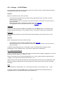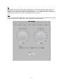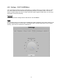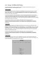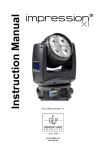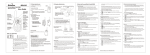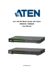
1
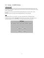
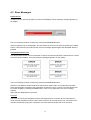
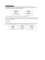
Laser Electronics Terminal Software
LETSoft
User Manual
Manual LETSoft
Rev. 1.0 Feb 2015
Contents
1
General................................................................................................................................. 3
1.1
Trademarks ............................................................................................................................ 3
1.2
General Safety Considerations .............................................................................................. 3
1.3
Laser Safety ........................................................................................................................... 3
1.3.1
Laser Radiation ......................................................................................................... 3
1.3.2
Laser Class................................................................................................................. 4
2
Introduction.......................................................................................................................... 5
3
Installation ........................................................................................................................... 6
4
User Interface ....................................................................................................................... 7
4.1
Main Window ........................................................................................................................ 7
4.2
Operating window ................................................................................................................. 8
4.3
5
4.2.1
Settings – LASER Menu ............................................................................................. 9
4.2.2
Settings – TEMPERATURE Menu ............................................................................ 11
4.2.3
Settings – TIMING Menu ........................................................................................ 13
4.2.4
Settings – COOLER Menu........................................................................................ 14
4.2.5
Settings – PILOT LASER Menu ................................................................................. 16
4.2.6
Settings – EXTERNAL INPUTS Menu ....................................................................... 17
4.2.7
Settings – CALIBRATION Menu ............................................................................... 18
Error Messages .................................................................................................................... 19
Reference ........................................................................................................................... 21
5.1
Menu and Toolbar ............................................................................................................... 21
2
1 General
The information given in this document is subject to change without notice.
©Copyright LASER ELECTRONICS 2015.
All rights reserved. Reproduction, adaptation, or translation without prior written permission is
prohibited, except as allowed under the copyright laws.
1.1 Trademarks
Products that are referred to in this document may be either trademarks and/or registered
trademarks of the respective owners. The publisher and the author make no claim to these
trademarks.
Microsoft and Windows are either registered trademarks or trademarks of Microsoft Corporation in
the United States and/or other countries.
1.2 General Safety Considerations
Before switching on the instrument, make sure it has been properly grounded through the supplied AC
power cable to a socket outlet with a protective earth contact. Any interruption of the grounding can
result in personal injury.
This instrument must be used under normal conditions and as specified, otherwise the protection
provided by the instrument could be impaired.
Always replace blown fuses with the same rating and acting speed.
ESD: Electrostatic discharge (ESD) on or near the connectors can damage electronic devices inside
the instrument. Personnel should touch the metal frame of the instrument for a second before touching
any connector.
1.3 Laser Safety
1.3.1 Laser Radiation
This instrument is designed to control laser diodes. Please read also very carefully the operating
instructions given by the manufacturer of the laser diode.
The radiation of the used laser diode may be visible or invisible. These products emit radiation in the
630 to 1560nm spectral region.
Use caution to avoid hazardous exposure to the beam. Take precautions to eliminate exposure
to a direct or reflected beam. Do not look directly into the beam of the laser diode under
conditions which exceeds the specified limits. Never observe the laser beam through optical
instruments.
3
1.3.2 Laser Class
The laser safety classification and the relevant parameters of the laser diode for normal operation are
indicated on the top of the laser diode. The laser radiation is emitted through the optics at the side of
the laser diode where the warning label is placed or at the fiber connector. The laser diodes are
classified according to EN 60825-1:94.
General warning label for laser radiation:
Label for laser radiation:
Label for relevant parameters (example) of the laser diode for normal operation and its statements:
Average radiant power at max. rep. frequ.:
Peak radiant power:
Pulse width:
Max. pulse repetition frequency:
Wavelength laser radiation:
Po
Pp
t
F
λ
4
2 Introduction
LATSoft is a test, control, and simulation tool. It allows you to monitor the device or to test the serial
communication of a single device and to control this device. LETSoft is easy to use and works on
almost any standard PC with Windows 8, Windows 7, Windows Vista, and Windows XP.
LETSoft will work with the COM communication ports provided by your operating system. Physically,
the port will be RS232 SUB D9 interfaces in many cases.
LETSoft has also been successfully tested with many popular USB-to-Serial converters, virtual null
modem software drivers, or Embedded Development tools that appear as a virtual COM port in
Windows.
This manual only refers to RS232 serial connections in detail.
5
3 Installation
Please read the whole operating instructions before using this Tool.
Installation of the LATSoft Tool
Download the LETSoft-Setup.exe from our website: http://laser-electronics.com
Extract the files in the archive.
After unzip, the LETSoft installation window opens automatically. Follow the installation instructions.
6
4 User Interface
4.1 Main Window
The main window of LETSoft is divided into two sections
4.1.1.1 Toolbar
Main LETSoft functions may be selected from the Toolbar.
4.1.1.2 Communication Window
Displays the communication structure of the serial interface.
7
If one of our devices is connected, it will be detected automatically. This opens a new window.
4.2 Operating window
Right it shows the measured laser diode current and voltage, the displayed power is calculated from
the laser diode current and the calibration points. Further, the laser power limit and laser mode is
displayed. Further, the laser current limit, the laser mode, the measured laser diode temperature T1 is
displayed. Cooler Current the current of cooler 1. “+” means heating current, and “-“ cooling current.
Within the mode menu you can set the optical power or the laser current. Under there is a Rotary knob
for setting laser diode current or laser diode power.
Bottom left is a button to turn on and off the laser diode.
When you press the Settings button opens a settings menu. In this menu, various parameters can be
set.
8
I - Laser Current
After schwitching on the instrument the set laser current is 0. It can be set up to laser current limit.
The laser diode is turned on by pressing the Laser key and the desired current is applied to the
laser diode. The actual current that is applied to the laser diode is displayed right at the display.
The current applied to the laser diode can also be varied when the laser diode is turned on by
modifying the desired current with the Rotary knob.
The laser diode is turned off by pressing the Laser button again.
P - Optical Power
After schwitching on the instrument the set optical power is 0. The set optical power will calculated into
the laser current by the calibration points (see menu calibration).
The calculated laser current will be shown immediately on position set laser current. The optical power
can also be varied when the laser diode is turned on. In this case the calculated laser current is
applied to the laser diode immediately.
4.2.1 Settings – LASER Menu
Laser Mode
The operational mode should only be changed when the laser diode is turned off. Nevertheless when
changing the operational mode, the laser diode is turned off automatically.
The following four operational modes can be selected and combined:
CW, No Time Limit
CW, Time Limit
Pulse, No Time Limit
Pulse, Time Limit
The laser diode is operated with a continuous current. The duration of the
operation is not time limited internally. The laser diode is turned on and off by
pressing the Laser key.
The laser diode is operated with a continuous current. The duration of the
operation is time limited according to the time limit, see menu TIMING. The
laser diode is turned on by pressing the Laser key and turned off
automatically after the set time limit.
The laser diode is operated with a pulsed current, see menu TIMING. The
duration of the operation is not time limited internally. The laser diode is
turned on and off by pressing the Laser key.
The laser diode is operated with a pulsed current. The duration of the
operation is time limited according to the time limit, see menu TIMING. The
laser diode is turned on by pressing the Laser key and turned off
automatically after the set time limit.
The desired mode is stored permanently in a non-volatile memory, even when the instrument is
switched off.
Laser Current Limit
Set the laser current limit to the indicated maximum current value of the laser diode which can be
found in the individual data sheet. Setting the appropriate current limit protects the laser diode from
being overloaded electrically and optically.
The value of the laser current limit is stored permanently in a non-volatile memory, even when the
instrument is switched off.
Remark: The maximum possible laser current limit is predefined by the instrument.
Power Monitor
If the laser diode is provided with a power monitor (photo diode), the power monitor voltage will be
shown. So, the calibrating can be make without a power meter.
E.g. the user increases laser current up to the power monitor voltage is 1,2V. From the laser diode
9
data sheet the user read 1,2V = 55W optical power. The actual laser current is 30A. I=30A, P=55W.
10
4.2.2 Settings – TEMPERATURE Menu
Within the temperature menu it can be set the temperature, the upper and lower temperature limit and
the control loop parameters of the PID-temperature controller for the first and second (optional) cooler.
Temperature
The value of the temperature can only be changed within the valid temperature range as defined by
the upper and lower temperature limit. The value for the temperature must be within 0°C to 50°C.
The desired temperature is stored permanently in a non-volatile memory, even when the instrument is
switched off.
Temperature limits
The operating laser diode and also the optional custom application should be protected by operating
setting temperature limits according to the specific datasheet provided by the manufacturer.
If the temperature of cooler 1 or cooler 2 (provided they are enabled) are out of the selected range, the
laser diode turned off automatically and an error message appears on the display, see section Error
messages.
The desired temperature limits are stored permanently in a nonvolatile memory, even when the
instrument is switched off.
Note:
The instrument accepts only inputs where the temperature of the upper limit is higher than the
temperature of the lower limit.
The value for the upper and lower temperature limit must be within 0°C to 50°C.
PID-Temperature control-loop parameters
The temperature controller is realized as a PID control loop for optimum performance (P means
proportional, I means integral and D means differential portion).
The control loop parameters can be set to values between 0 and 100. The default settings which
provide usually good controlling are as follows:
Cooler 1
Portion
Value
P
30
I
10
D
0
Cooler 2
Portion
Value
P
20
I
3
D
0
The desired control loop parameter is stored permanently in a non-volatile memory, even when the
instrument is switched off.
If the control loop is not stable after some minutes of active operating, e.g. the temperature is
oscillating between two values which differ about 0.5 °C, the P-portion should be decreased.
If the measured temperature does not become equal to the desired temperature, the I-portion should
be increased.
Remark:
In general a larger P-portion or a smaller I-portion speeds up the settling time of the control loop, but
with the first the controller might oscillate and with the latter there might be a permanent difference
between the actual temperature and the desired temperature.
Due to the large heat capacity and heat load of high power laser diodes and the needed heatsinks, it
takes some minutes until a stable operating point is reached.
11
12
4.2.3 Settings – TIMING Menu
Within the Timing menu it can be set the pulse width, the pulse period and the time limit.
Confirm the selection with the UP/DOWN buttons or enter the value directly. The desired value is
stored permanently in a non-volatile memory, even when the instrument is switched off.
Notes:
The two parameters “pulse width” and “pulse period” depend on each other. The instrument will
automatically force the other parameter within the valid range depending on the change of the
selected parameter.
Values of the pulse width which are larger than the pulse period are not accepted by the instrument.
The pulse width must be within the range of 5.0 ms to 490 ms.
The pulse period must be within the range of 10 ms to 500 ms.
The time limit must be within the range of 0.1 s to 99.9 s.
13
4.2.4 Settings – COOLER Menu
The Laser Diode Controller can work without, with one or with two cooler controllers. Before working,
the appropriate cooler must be enabled.
Attention
Before you enable a cooler, make sure that:
-
the Laser Diode Controller was purchased with the appropriate cooler controller, see menu
CONFIG (device manual)
the correct sensor type is connected on the correct connector, see section Connectors pin-out
(device manual),
the correct sensor type is selected by software, see menu COOLER,
the appropriate cooler current limit is set, see menu COOLER.
Cooler 1/2
Change the setting between ENABLE and DISABLE with the ON/OFF button. The desired cooler
setting is stored permanently in a non-volatile memory, even when the instrument is switched off.
Sensor 1/2
The Laser Diode Controller can work with three several temperature sensor types: NTC, PT100,
PT1000.
Attention
Before changing the sensor type, make sure that:
-
the appropriate cooler controller is disabled, see menu COOLER,
the correct sensor type is connected on the correct connector, see section Connectors pin-out
(device manual).
Change the setting between NTC, PT100 and PT1000. The desired sensor setting is stored
permanently in a non-volatile memory, even when the instrument is switched off.
Imax – cooler current limit 1/2
Cooler 1 is usually used for cooling the laser diode and delivered up to 600W ±13A@±48V. The cooler
current limit can be set from 0 .. 12A or 0 .. 13A.
Cooler 2 is usually used for customized applications (e.g.: laser crystal cooling) and delivered up to
±3A@±5V. The cooler current limit can be set from 0 .. 3A.
Always set the current limit to the maximum current value which can be found in the data sheet of the
heat sink. Setting the appropriate current limit protects the peltier elements from being overloaded
electrically.
Note:
The set limit acts in both direction. E.g. current limit 2,5A means a current range –2,5A …+2,5A.
Confirm the selection with the Rotary knob. The desired current limit is stored permanently in a
nonvolatile memory, even when the instrument is switched off.
14
Fan
Normally the heat sink is provided with a powerfully fan. In most cases the full fan power will not be
used. For that reason the fan voltage can varied between 6 .. 12V. Confirm the selection with the
Rotary knob. The desired fan voltage is stored permanently in a non-volatile memory, even when the
instrument is switched off. If cooler 1 is set disable the fan is switch off.
Note:
Only do reduce the fan voltage either if the laser diode is in operation for short periods or with reduced
power. Increase the fan voltage if the cooler cannot held the set temperature.
15
4.2.5 Settings – PILOT LASER Menu
The Laser Diode Controller can drive a pilot laser up to 300mA. Before you enable, make sure that
your Laser Diode was purchased with the appropriate pilot laser, see Delivery Note. This source
deliver constant voltage (+5,0V) for a build in pilot laser (with integrated small driver). Do not drive a
laser diode on this source directly.
Pilot Laser
Change the pilot laser setting between ON and OFF with the Button.
Power
The pilot laser power can be reduced by a PWM (pulse width modulation) of its supply voltage. It can
be set to values between 1% and 100%. The desired value is stored permanently in a non-volatile
memory, even when the instrument is switched off.
16
4.2.6 Settings – EXTERNAL INPUTS Menu
Some Laser Electronics devices provides an external analogue modulation input, an external
triggering input and an external triggering output.
Analogue Input
The analogue modulation signal is applied to the Analog In connector at the front panel. The valid
range for the signal is 0 V to +5 V. The transfer function for the applied signal voltage to the laser
diode current is 20 A / V. The modulation bandwidth is DC to 100 Hz. E.g.: A signal voltage of 2.5 V
refers to a laser diode current of 50A.
For maximum protection of the laser diode the current of the laser diode is limited to the selected
current limit. Therefore it might happen that the analogue modulated laser light is distorted due to the
clipping of the maximum applied current to the laser diode. In order not to distort the analogue
modulated laser light, pay attention not to exceed the valid analogue modulation signal level according
to the transfer function for the current.
The laser diode should be turned on with the Laser button prior to the external inputs.
Change the input setting between ENABLE and DISABLE with the Option button. The desired
external input mode is stored permanently in a non-volatile memory, even when the instrument is
switched off.
Trigger Input
The trigger signal is applied to the Trig In connector (9) at the front panel. The valid range for the
signal is according the specifications for TTL signals (Low: 0 V < U < 0.8V, High: 2.4 V < U < 5 V). The
bandwidth is DC to 100 Hz. An applied TTL-low signal leads to a turned off laser. An applied TTL-high
signal leads to a turned on laser with the set laser diode current, see menu LASER. E.g.: If the laser
diode current is set to „I = 25A“, this current is applied to the laser diode when a TTL-high signal is
detected as external trigger signal.
The laser diode should be turned on with the Laser button prior to the external inputs.
Change the input setting between ENABLE and DISABLE with the Option button. The desired
external input mode is stored permanently in a non-volatile memory, even when the instrument is
switched off.
Trigger Output
The signal on the trigger output connector Trig Out (10) provides a synchronization between the
internally generated pulses, as specified by the pulse operational mode, and the external trigger. The
output is according to the specifications for TTL signals.
17
4.2.7 Settings – CALIBRATION Menu
Calibrations Points
Because the laser diode current and its optical output power are approximately linear to each other,
it is possible to calculate the optical power from the current if the user set two measured pairs of laser
current / optical power.
E.g. the user set current to 20A and measured 30W optical power by a power meter. I1=20A,
P1=30W.
Then he set current to 30A and measured 55W optical power. I2=30A, P2=55W.
Note:
The deviations from the correct value can increase with distance from the measured value.
Confirm the selection with the UP/DOWN buttons or enter the value directly. The desired value is
stored permanently in a non-volatile memory, even when the instrument is switched off.
18
4.3 Error Messages
Interlock error
If interlock loop is opened, the laser is turned off immediately and the following message appears on
the display:
The error massage must be confirmed by pressing the Clear Error button.
After the interlock loop is closed again, the laser diode can be turned on again by pressing the Laser
button. If the interlock loop is still opened, the error message appears again after the Laser button is
pressed.
Temperature sensor error
If an temperature sensor circuit is shortened or opened, the laser diode and the thermoelectric coolers
are turned off immediately. One of the following messages appears on the display:
The error massage must be confirmed by pressing the Clear Error button.
After the Laser Diode Controller detects the temperature sensor again, the temperature controller
starts working again according to the parameters as before the error occurred. The laser diode must
be turned on again by pressing the Laser button. If the error is still present, the error message
appears
again after the Laser button is pressed.
Remarks:
The error concerning the temperature sensor also appears if the connector for the thermoelectric
cooler and the temperature sensor (also named connector for the heat sink) is not connected to the
instrument. Before providing this connection, the Laser Diode Controller has to be turned off.
19
Temperature range error
If the temperature of a cooler is out of the range as defined with the temperature limits in
TEMPERATURE menu, the laser diode and the thermoelectric coolers are turned off immediately.
One of the following messages appears on the display:
The error massage must be confirmed by pressing the Clear Error button.
After the laser diode reaches the allowed temperature range again, the laser diode can be turned on
again by pressing the Laser button. If the error is still present, the error message appears again after
the Laser button is pressed.
Overload error
If a device module of the Laser Diode Controller overloaded, the laser diode and the thermoelectric
coolers are turned off immediately. One of the following messages appears on the display:
20
5 Reference
5.1 Menu and Toolbar
Terminal Menu
Exit
Quit LETSoft
Settings Menu
Serial Port Settings
In this menu you can set whether the search for the device should be done automatically, or you can
make the entry manually.
Demo Menu
Start Demo Version
Opens the demo version of LETSoft. There, one of LASER ELECTRONICS devices is simulated.
Help Menu
USB-Driver
coming soon
Support
This menu item will take you to our website. There you can get in contact with us.
21