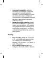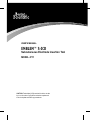
1
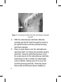
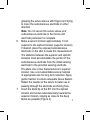
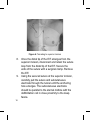
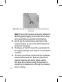
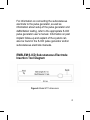
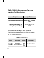
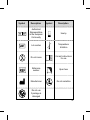
USER'S MANUAL
EMBLEM™ S-ICD
Subcutaneous Electrode Insertion Tool
MODEL 4711
CAUTION: Federal law (USA) restricts this device to sale
by or on the order of a physician trained or experienced
in device implant and follow-up procedures.
EMBLEM is a trademark of Boston Scientific.
Table of Contents
Description1
Related Information
1
Intended Audience
2
Indications for Use
2
Contraindications2
Warnings2
General3
Handling4
Implantation5
Precautions6
Clinical Considerations
6
Sterilization and Storage
6
Implantation7
Potential Adverse Events
8
Using the EMBLEM S-ICD Subcutaneous Electrode Insertion Tool
10
Items Included in Package
10
Implanting the S-ICD System
11
Creating the Device Pocket
13
Implanting the EMBLEM S-ICD Subcutaneous Electrode
14
EMBLEM S-ICD Subcutaneous Electrode Insertion Tool Diagram
21
EMBLEM S-ICD Subcutaneous Electrode Insertion Tool Specifications22
Definitions of Package Label Symbols
22
Warranty Disclaimer
24
Description
The EMBLEM™ S-ICD subcutaneous electrode
insertion tool (the “EIT”) is a component of the Boston
Scientific S-ICD System, which is prescribed for
patients when cardiac arrhythmia management is
warranted. The EIT is used to create a subcutaneous
tunnel to facilitate implantation of the EMBLEM S-ICD
subcutaneous electrode. The EMBLEM S-ICD EIT is
also compatible with the Cameron Health Model 3010
Q-TRAK subcutaneous electrode.
Related Information
For additional information about other components of
the S-ICD System, refer to the following:
• EMBLEM S-ICD Pulse Generator User’s
Manual
• EMBLEM S-ICD Subcutaneous Electrode
User’s Manual
• EMBLEM S-ICD Programmer User’s Manual
A summary of the S-ICD System Clinical
Investigation, including observed adverse events, can
be obtained by contacting Boston Scientific using the
information on the back cover.
1
Intended Audience
This literature is intended for use by professionals
trained or experienced in device implant and/or followup procedures.
Indications for Use
The S-ICD System is intended to provide defibrillation
therapy for the treatment of life threatening ventricular
tachyarrhythmias in patients who do not have
symptomatic bradycardia, incessant ventricular
tachycardia, or spontaneous, frequently recurring
ventricular tachycardia that is reliably terminated with
anti-tachycardia pacing.
Contraindications
Unipolar pacing and impedance-based features are
contraindicated for use with the S-ICD System.
Warnings
Note: Before using the S-ICD System, read and
follow all warnings and precautions provided in the
EMBLEM S-ICD Pulse Generator User’s Manual.
2
General
•
•
Labeling knowledge. Read this manual
thoroughly before using the S-ICD System to
avoid damage to the pulse generator and/or
subcutaneous electrode. Such damage can
result in patient injury or death.
For single patient use only. Do not
reuse, reprocess, or resterilize. Reuse,
reprocessing, or resterilization may
compromise the structural integrity of the
device and/or lead to device failure which, in
turn, may result in patient injury, illness, or
death. Reuse, reprocessing, or resterilization
may also create a risk of contamination of
the device and/or cause patient infection
or cross-infection, including, but not limited
to, the transmission of infectious disease(s)
from one patient to another. Contamination
of the device may lead to injury, illness, or
death of the patient.
3
•
•
Component Compatibility. All Boston
Scientific S-ICD implantable components
are designed for use with the Boston
Scientific or Cameron Health S-ICD System
only. Connection of any S-ICD System
components to a non-compatible component
will result in failure to deliver life-saving
defibrillation therapy.
Backup defibrillation protection. Always
have external defibrillation equipment and
medical personnel skilled in CPR available
during implant and follow-up testing. If not
terminated in a timely fashion, an induced
ventricular tachyarrhythmia can result in the
patient’s death.
Handling
•
•
4
Proper Handling. Handle the components
of the S-ICD System with care at all times
and maintain proper sterile technique.
Failure to do so may lead to injury, illness, or
death of the patient.
Do not damage components. Do not
modify, cut, kink, crush, stretch or otherwise
•
damage any component of the S-ICD
System. Impairment to the S-ICD System
may result in an inappropriate shock or
failure to deliver therapy to the patient.
Handling the subcutaneous electrode.
Use caution handling the subcutaneous
electrode connector. Do not directly contact
the connector with any surgical instruments
such as forceps, hemostats, or clamps. This
could damage the connector. A damaged
connector may result in compromised
sealing integrity, possibly leading to
compromised sensing, loss of therapy, or
inappropriate therapy.
Implantation
•
System dislodgement. Use appropriate
anchoring techniques as described in
the implant procedure to prevent S-ICD
System dislodgement and/or migration.
Dislodgement and/or migration of the S-ICD
System may result in an inappropriate shock
or failure to deliver therapy to the patient.
5
Precautions
Clinical Considerations
•
•
Pediatric Use. The S-ICD System has not
been evaluated for pediatric use.
Available Therapies. The S-ICD System
does not provide long-term bradycardia
pacing, cardiac resynchronization therapy
(CRT) or anti-tachycardia pacing (ATP).
Sterilization and Storage
•
•
6
If package is damaged. The electrode
insertion tool is sterilized with gamma
irradiation and is packaged in a sterile
container. When the electrode insertion
tool is received, it is sterile provided the
container is intact. If the packaging is wet,
punctured, opened, or otherwise damaged,
return the electrode insertion tool to Boston
Scientific.
Use by date. Use the electrode insertion tool
before or on the USE BY date on the package
label because this date reflects a validated
•
shelf life. For example, if the date is January
1, do not use on or after January 2.
Storage Temperature. The recommended
storage temperature range is -18°C to +55°C
(0°F to +131°F).
Implantation
•
•
•
Creating the subcutaneous tunnel.
Use only the electrode insertion tool to
create the subcutaneous tunnel when
implanting and positioning the subcutaneous
electrode. Avoid tunneling close to any other
subcutaneously implanted medical devices
or components, for example an implantable
insulin pump, drug pump, or ventricular
assist device.
Suture location. Suture only those areas
indicated in the implant instructions.
Do not suture directly over subcutaneous
electrode body. Do not suture directly
over the subcutaneous electrode body, as
this may cause structural damage. Use
the suture sleeve to prevent subcutaneous
electrode movement.
7
•
Sternal wires. When implanting the S-ICD
system in a patient with sternal wires,
ensure that there is no contact between the
sternal wires and the distal and proximal
sense electrodes (for example, by using
fluoroscopy). Compromised sensing can
occur if metal-to-metal contact occurs
between a sense electrode and a sternal
wire. If necessary, re-tunnel the electrode
to ensure sufficient separation between the
sense electrodes and the sternal wires.
Potential Adverse Events
Potential adverse events related to implantation of the
S-ICD System may include, but are not limited to, the
following:
• Acceleration/induction of atrial or ventricular
arrhythmia
• Adverse reaction to induction testing
• Allergic/adverse reaction to system or
medication
• Bleeding
• Conductor fracture
• Cyst formation
• Death
8
•
•
•
•
•
•
•
•
•
•
•
•
•
•
•
•
•
•
•
•
•
•
•
•
•
Delayed therapy delivery
Discomfort or prolonged healing of incision
Electrode deformation and/or breakage
Electrode insulation failure
Erosion/extrusion
Failure to deliver therapy
Fever
Hematoma/seroma
Hemothorax
Improper electrode connection to the device
Inability to communicate with the device
Inability to defibrillate or pace
Inappropriate post-shock pacing
Inappropriate shock delivery
Infection
Keloid formation
Migration or dislodgement
Muscle/nerve stimulation
Nerve damage
Pneumothorax
Post-shock/post-pace discomfort
Premature battery depletion
Random component failures
Stroke
Subcutaneous emphysema
9
•
•
•
Surgical revision or replacement of the
system
Syncope
Tissue redness, irritation, numbness or
necrosis
If any adverse events occur, invasive corrective action and/
or S-ICD System modification or removal may be required.
Patients who receive an S-ICD System may develop
psychological disorders that include, but are not
limited to, the following:
• Depression/anxiety
• Fear of device malfunction
• Fear of shocks
• Phantom shocks
Using the EMBLEM S-ICD Subcutaneous
Electrode Insertion Tool
Items Included in Package
The EMBLEM S-ICD subcutaneous electrode
insertion tool has been sterilized with gamma
irradiation and is packaged in a sterile container that
10
is suitable for use in the operating field. Store in a
clean, dry area. Each package contains the following:
• One EMBLEM S-ICD subcutaneous
electrode insertion tool, Model 4711
• One EMBLEM S-ICD Subcutaneous
Electrode Insertion Tool User’s Manual
Implanting the S-ICD System
This section presents the information necessary
for implanting the EMBLEM S-ICD subcutaneous
electrode using the EMBLEM S-ICD subcutaneous
electrode insertion tool (the “EIT”).
Warning: All Boston Scientific S-ICD implantable
components are designed for use with the Boston
Scientific or Cameron Health S-ICD System only.
Connection of any S-ICD System components to a
non-compatible component will result in failure to
deliver life-saving defibrillation therapy.
The S-ICD System is designed to be positioned using
anatomical landmarks. However, it is recommended
to review a pre-implant chest x-ray in order to
11
confirm that a patient does not have notably atypical
anatomy (e.g., dextrocardia). Additionally, it is not
recommended to deviate from the implant instructions
to accommodate for physical body size or habitus,
unless a pre-implant chest x-ray has been reviewed.
The device and subcutaneous electrode are typically
implanted subcutaneously in the left thoracic
region (Figure 1). The EIT is used to create the
subcutaneous tunnels in which the electrode is
inserted.
Figure 1: Placement of the S-ICD System
12
Creating the Device Pocket
The device is implanted in the left lateral thoracic
region. To create the device pocket, make an incision
such that the device can be placed in the vicinity of
the left 5th and 6th intercostal spaces and near the
mid-axillary line (Figure 2). This can be accomplished
by making an incision along the inframammary
crease.
Figure 2: Creating the device pocket
13
Implanting the EMBLEM S-ICD Subcutaneous
Electrode
The procedure described below is one of several
surgical approaches that can be used to appropriately
implant and position the electrode. Regardless of
the surgical approach, the defibrillation coil must be
positioned parallel to the sternum, in close proximity
to, or in contact with the deep fascia, approximately
2 cm from the sternal midline (Figure 1). In addition,
good tissue contact with the electrode and pulse
generator is important to optimize sensing and
therapy delivery. Use standard surgical techniques
to obtain good tissue contact. For example, keep the
tissue moist and flushed with sterile saline, express
any residual air out through the incisions prior to
closing and, when closing the skin, take care not to
introduce air into the subcutaneous tissue.
1. Make a small, 2 cm horizontal incision at the
xiphoid process (xiphoid incision).
Note: If desired, in order to facilitate attachment
of the suture sleeve to the fascia following
electrode placement, two suture ties to the fascia
14
can be made at the xiphoid incision prior to
continuing.
2. Insert the distal tip of the EIT at the xiphoid
incision and tunnel laterally until the distal tip
emerges at the device pocket.
Note: The EIT is malleable and can be curved to
match the patient’s anatomical profile.
Caution: Use only the electrode insertion
tool to create the subcutaneous tunnel when
implanting and positioning the subcutaneous
electrode. Avoid tunneling close to any other
subcutaneously implanted medical devices or
components, for example an implantable insulin
pump, drug pump, or ventricular assist device.
3. Using conventional suture material, tie the
anchoring hole of the subcutaneous electrode to
the EIT creating a long 15-16 cm loop (Figure 3).
15
Figure 3: Connecting the distal end of the subcutaneous electrode
to the EIT
4. With the subcutaneous electrode attached,
carefully pull the EIT back through the tunnel to
the xiphoid incision until the proximal sensing
electrode emerges.
5. Place a suture sleeve over the subcutaneous
electrode shaft 1 cm below the proximal sensing
electrode. Using the preformed grooves, bind
the suture sleeve to the subcutaneous electrode
shaft using 2-0 silk or similar non-absorbable
suture material, making sure not to cover the
proximal sensing electrode. Check the suture
sleeve after anchoring to assure stability by
16
grasping the suture sleeve with fingers and trying
to move the subcutaneous electrode in either
direction.
Note: Do not secure the suture sleeve and
subcutaneous electrode to the fascia until
electrode placement is complete.
6. Make a second incision approximately 14 cm
superior to the xiphoid incision (superior incision).
If desired, place the exposed subcutaneous
electrode on the skin to make this measurement.
The distance between the superior and xiphoid
incisions must accommodate the portion of the
subcutaneous electrode from the distal sensing
electrode to the proximal sensing electrode.
Pre-place one or two fascial sutures in superior
incision. Use a non-absorbable suture material
of appropriate size for long term retention. Apply
gentle traction to ensure adequate tissue fixation.
Retain the needle on the suture for later use in
passing through the electrode anchoring hole.
7. Insert the distal tip of the EIT into the xiphoid
incision and tunnel subcutaneously towards the
superior incision, staying as close to the deep
fascia as possible (Figure 4).
17
Figure 4: Tunneling to superior incision
8. Once the distal tip of the EIT emerges from the
superior incision, disconnect and retain the suture
loop from the distal tip of the EIT. Secure the
ends of the suture with a surgical clamp. Remove
the EIT.
9. Using the secured suture at the superior incision,
carefully pull the suture and subcutaneous
electrode through the tunnel until the anchoring
hole emerges. The subcutaneous electrode
should be parallel to the sternal midline with the
defibrillation coil in close proximity to the deep
fascia.
18
10. Cut and discard the suture material.
11. At the xiphoid incision, secure the suture sleeve
with the subcutaneous electrode to the fascia
using 2-0 silk or similar non-absorbable suture
material.
Warning: Use appropriate anchoring techniques
as described in the implant procedure to prevent
S-ICD System dislodgement and/or migration.
Dislodgement and/or migration of the S-ICD
System may result in an inappropriate shock or
failure to deliver therapy to the patient.
Caution: Do not suture directly over the
subcutaneous electrode body, as this may cause
structural damage. Use the suture sleeve to
prevent subcutaneous electrode movement.
Caution: Suture only those areas indicated in the
implant instructions.
Note: Ensure that the suture is securely fastened
to fascia by gently tugging on the suture prior
to tying to the suture sleeve and subcutaneous
electrode.
12. At the superior incision, secure the anchoring
hole to the fascia using the pre-placed sutures
from step 6 (Figure 5).
19
Figure 5: Anchoring the distal electrode tip of the subcutaneous
electrode
Note: Ensure that the suture is securely fastened to
fascia by gently tugging on the suture prior to tying
to the subcutaneous electrode anchoring hole.
13. Gently tug the subcutaneous electrode at the
superior incision to ensure the anchoring hole is
secured to the fascia.
14. To dispose of the EIT, return the used product to
the original package, then dispose in a biohazard
container.
15. To ensure good tissue contact with the implanted
subcutaneous electrode, flush the xiphoid and
superior incisions with sterile saline solution
and apply firm pressure along the electrode to
express any residual air out through the incisions
prior to closing.
20
For information on connecting the subcutaneous
electrode to the pulse generator, as well as
information about setup of the pulse generator and
defibrillation testing, refer to the appropriate S-ICD
pulse generator user’s manual. Information on post
implant follow-up and explant of the system can
also be found in the S-ICD pulse generator and/or
subcutaneous electrode manuals.
EMBLEM S-ICD Subcutaneous Electrode
Insertion Tool Diagram
Figure 6: Model 4711 dimensions
21
EMBLEM S-ICD Subcutaneous Electrode
Insertion Tool Specifications
Table 1: Specifications
Component
Specification
Electrode insertion tool materials
Acrylonitrile-butadienestyrene (ABS), stainless
steel
Transportation, Handling and
Storage Temperature Range
-18°C to +55°C (0°F to
+131°F)
Definitions of Package Label Symbols
The following table defines the symbols that appear
on the product packaging.
Table 2: Packaging symbols
Symbol
Description
Sterilized by
gamma irradiation
22
Symbol
Description
Date of manufacture
Symbol
Description
Symbol
Description
Authorized
Representative
in the European
Community
Use by
Lot number
Temperature
limitation
Do not reuse
Consult instructions
for use
Reference
number
Open here
Manufacturer
Do not resterilize
Do not use
if package is
damaged
23
Warranty Disclaimer
Except as otherwise provided herein, Boston
Scientific disclaims all express and implied warranties
for this product, including without limitation any
implied warranties of merchantability or fitness for
a particular purpose. Boston Scientific’s obligations
under any warranty provided herein shall be limited
strictly to replacement of the product. Buyer assumes
all risk of loss or damages arising from use of this
product.
24
© 2015 Boston Scientific Corporation or its
affiliates. All rights reserved.
Boston Scientific
4100 Hamline Avenue North
St. Paul, MN 55112-5798 USA
www.bostonscientific.com
1.800.CARDIAC (227.3422)
+1.651.582.4000
359301-001 EN US 2015-02
*359301-001*