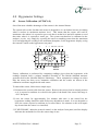
1
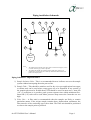
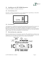
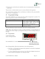
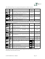
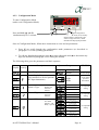
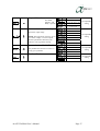
dewTEC
DS2000 dewpoint meter
instruction manual
alpha moisture systems
alpha house, 96 city road
bradford, BD8 8ES
england
Tel: +44 1274 733100
Fax: +44 1274 733200
Email: [email protected]
Web: www.amsystems.co.uk
dewTEC DS2000 User’s Manual
Page ii
HOW TO USE THIS MANUAL
IMPORTANT: USER MUST READ THIS MANUAL BEFORE OPERATING THE
dewTEC DS2000 DEWPOINT METER
This manual comprises of six sections viz.
Section 1
General Description
Includes general description outlining the main features of the unit.
Section 2
Installation Instructions
Safety Information
Unpacking your dewTEC DS2000 and Moisture Sensor
Sensor Care
Sensor Installation
Dew Point Meter Installation
Electrical Connections
External AUTOCAL Control
Section 3
Operating Instructions
Start Up
Front Panel Display and Keys
Viewing Pre-Set Parameters
Alarm Settings
Resetting a Latched Alarm
Section 4
dewTEC DS2000 Settings
AUTOCAL
Factory Set Parameters
Calibration Data, Analogue Output Span, Offset, Filter, Serial
Communications, Display Colour, Lock, Help, Alarm Mode and
Direction, Analogue Output Type, Totaliser.
Section 5
RS485 Serial Communications
Data Format
Protocol
Message Form
Section 6
Maintenance and Trouble Shooting
Maintenance
Problem Guide
Appendices
Specifications and General Arrangement
dewTEC DS2000 User’s Manual
Page iii
dewTEC DS2000 User’s Manual
Page iv
CONTENTS
HOW TO USE THIS MANUAL
iii
1.0
1
General Description & Features
1.1
1.2
Description
Main Features
Dewpoint Meter Features
Sensor Features
1
1
1
1
Installation Instructions
2
1.2.1
1.2.2
2.0
2.1
2.1.1
2.1.2
2.2
2.3
2.4
2.5
2.6
2.6.1
2.6.2
2.7
2.7.1
2.7.2
2.7.3
2.7.4
2.7.5
2.7.6
2.7.7
3.0
9
9
10
11
12
12
Hygrometer Settings
4.2.1
4.2.2
13
Sensor Calibration (AUTOCAL)
Programmed Settings
Program Mode
Configuration Mode
13
14
14
16
Serial Communications
5.1
5.2
5.3
5.3.1
5.3.2
5.4
6.0
9
Start Up
Front Panel Display and Keys
Viewing Operating Mode Parameters
Setting the Alarms and hysterisis
Hysterisis Operation
Resetting a latched Alarm
4.1
4.2
5.0
2
2
2
2
2
3
5
6
6
6
6
7
7
7
7
8
8
8
Operating Instructions
3.1
3.2
3.3
3.4
3.5
3.6
4.0
Safety Information
Warning
Isolation
Unpacking your dewTEC DS2000 Dewpoint Meter and Sensor
Sensor Care
Installing the air/gas sampling system
Installing and commissioning the sensor
Installing your dewTEC DS2000 Hygrometer
Panel mounting cut out
Panel mounting
Electrical interface connections
Mains (line) supply or optional DC Input
Sensor Connection
Alarm Relay Outputs
Linear (Analogue re-transmission) Output
Alarm Transistor Open Collector Outputs
Serial Communications Output
External Autocal Control
18
Data Format/Baud Rate
Protocol
Message Format
Message Form 1
Message Form 2
Error Conditions
18
18
18
18
19
19
Maintenance and Troubleshooting
6.1
6.2
20
Maintenance
Problem Guide
20
20
Appendices
22
Appendix A – Product Specification
Appendix B – General Arrangement
22
23
Document No. 1125 Issue 4 12/01/05
dewTEC DS2000 User’s Manual
Page v
dewTEC DS2000 User’s Manual
Page vi
1.0 General Description & Features
1.1
Description
The dewTEC DS2000 is a DIN style panel mounted dewpoint meter, designed to accurately
measure the dewpoint in gas or dry compressed air. The operating range of the unit is factory
set to the Moisture Sensor supplied with the unit. Process moisture value in factory set units
of °C, °F or PPM(V) is indicated, by the dewTEC DS2000 dewpoint meter, on a large five
digit seven segment display
The main external body of the Ultra High Capacitance Moisture Sensor is made of plated steel
and a stainless steel filter guard protects the sensing element within it.
The sensor can be located up to one kilometre away from the dew point meter.
1.2
Main Features
1.2.1
Dewpoint Meter Features
The dewTEC DS2000 dewpoint meter’s main features are:
•
•
•
•
•
•
•
•
•
•
•
•
1.2.2
Display: Five large LED digits and one small LED digit, both with seven segments.
Two alarm status LED’s.
User programmable LED indication to display in either Green or Red and can be
programmed to change colour when in alarm condition.
Programmable via push button keys on front panel or PC (optional extra).
Alarms: Two, independent, fully user programmable isolated relays with open
collector outputs. Programmable lock out to avoid unauthorised tamper.
Displays maximum and minimum values.
Displays elapsed time from alarm condition.
Factory set calibration data in °C, °F or PPM.
Factory set current (mA) OR voltage (mV) analogue output. Isolated and user
programmable to span over any range, within the overall range of the sensor.
RS485 serial output with 1-99 address settings.
90 - 264V, 50/60Hz or 22-50V DC Universal input power supply.
Accuracy ± 2°C dewpoint (or equivalent in other moisture units).
AUTOCAL feature for automatic calibration adjustment.
Sensor Features
The sensor main features are:
•
•
•
•
Various dewpoint ranges available. Range ident on sensor packaging.
Conditioned for long term stability.
Can be located up to 1km from the dewTEC DS2000 dewpoint meter, connected by a
low impedance coaxial cable.
ATEX Certified for use in potentially explosive areas with suitable Zener Barrier.
dewTEC DS2000 User’s Manual
Page 1
2.0 Installation Instructions
2.1
Safety Information
Before installation please read the safety information below.
2.1.1
Warning
Suitably qualified personnel must install the equipment and care must be taken, as high
voltages may be present on the instrument terminals. The instrument must be mounted in a
position that provides protection behind the panel to at least IP20. Local regulations regarding
electrical installation should be rigidly observed.
2.1.2
Isolation
The power supply terminals and associated internal circuitry are isolated from all other parts
of the equipment, in accordance with EN61010-1, for connection to a category II supply
(pollution degree 2). Any terminals or wiring connected to the input or output, which is
accessible in normal operation, must only be connected to signals complying with the
requirements for Safety Extra Low Voltage (SELV) circuits.
Follow wiring instructions described later in this section.
2.2
Unpacking your dewTEC DS2000 Dewpoint Meter and Sensor
Once unpacked, the items should be examined for any obvious external damage. Any
evidence of damage or mishandling should be notified to your carrier immediately.
The items should include dewTEC DS2000 dewpoint meter, Moisture Sensor packed in a
metal canister, instruction manual, sensor connecting cable and any optional extras if ordered.
The sensor is packed separately in a waterproof metal canister, with desiccant, to protect it
from excessive moisture exposure during transit. The sensor should be inspected for damage
then immediately stored in its canister until ready for installation. Retain the packaging for
future use, ensuring the sensor canister cap is tightly screwed to preserve the desiccant.
2.3
Sensor Care
Very special care must be taken not to damage the sensing element, for example by touching
or making any other physical contact, as this may damage the sensing surface and render the
Sensor useless.
Additionally, the following guidelines should always be followed:
• For any reason whatsoever DO NOT REMOVE THE SENSOR GUARD OR
ATTEMPT TO CLEAN THE SENSING ELEMENT WITHIN IT. The Sensor is
NOT user serviceable and does NOT contain any user replaceable parts. In the event
of a problem follow the problem guide at the end of this manual.
dewTEC DS2000 User’s Manual
Page 2
• When not in use the sensor should always be stored in the desiccant contained metal
canister.
• The sensor should not be exposed to ambient conditions for considerably long periods.
• Exposure of the sensor to liquid water or condensing atmospheres should be avoided.
• The sensor should not be exposed to corrosive contaminants such as chlorine, ammonia
or mercury vapours. These gasses will gradually corrode the sensor and cause a loss of
sensitivity, hence affecting the system accuracy.
• Avoid heat sources and extreme temperatures when choosing installation site
• Ensure the sample gas exposed to the sensor is clean as contaminants such as oil, glycol
and heavy hydrocarbons can mask the sensing element, thus affecting the system
response. (If this is an issue contact your dewTEC DS2000 supplier for advice on a
suitable sample system.)
2.4
Installing the air/gas sampling system
The piping installation schematic diagram below shows all components, which could be used
in a dry gas measurement application although not all the items shown will be required for
every installation.
Care should be taken to ensure that the sample presented to the measuring sensor is not
contaminated with any component that will damage, contaminate or affect the sensor in a way
that will impair the system accuracy.
It is strongly recommended that the sample should not contain particulate matter, oil or other
heavy hydrocarbon condensate. If these components contaminate the sample system and/or
the measuring sensor, the system response time will be lengthened, although the sensor
calibration will not be effected.
The sample must not contain Ammonia, Chlorine, Ozone or any wet acid vapours or
liquid as these will permanently damage the sensor and impair calibration accuracy.
The flow rate, although not critical to the sensor measurement, should be low enough to avoid
abrasion to the sensor surface without being so low as to extend the system response time to
an unacceptable level. In general, a flow rate of between 2 and 3 litres/min at NTP will give
the right balance.
The sensor is a variable capacitor, which is directly affected by changes in partial pressure of
water vapour, and these changes, that are proportional to the dew/frost point temperature, are
displayed on the hygrometer display.
The measuring sensor can be installed directly into the process line but this does create
problems with access for maintenance and calibration. It is for these reasons that we
recommend that the sensor be installed in a bypass, fast loop or total loss sample system
where the sensor is accessible without interrupting the main process flow line.
dewTEC DS2000 User’s Manual
Page 3
Piping installation Schematic
4
A
5
7
6
P
2
1
0
1
1
4B
9
3
1
Main
Proces
s
Li
Notes
a.
b.
8
The sample point should be on the upper surface of the horizontal pipe, or from
a vertical section of pipe, wherever possible.
The sample tube should run upwards from the sample point. If this is not
possible, then an inspection port or drain tap should be installed at the lowest
point in the sample system.
Piping Schematic Component Index
1) Sample Isolation Valve - This is a recommended item as it allows access to the sample
system without interrupting the main process line.
2) Sample Tube – This should be stainless steel for dry air or gas applications but copper
or carbon steel can be used where wetter gases are to be measured. If any section of
the sample tube must be flexible then PTFE should be used. In most cases, 3mm OD
(1/8”) is sufficient as it provides good system response time within minimum flow.
6mm OD (1/4”) tube can be used where pressure drops across the 3mm tube are too
high
3) Filter Unit – A filter unit is recommended when the samples are likely to contain
particulate matter. If the air/gas sample contains heavy hydrocarbon condensate, the
filter must be of the coalescing type with a drain. The filter unit should be positioned
as close to the sample point as practical.
dewTEC DS2000 User’s Manual
Page 4
4) Pressure Reduction Valve or Pressure Regulator – If the sample is to be measured at
atmospheric pressure then the valve 4A should be fitted and 4B omitted from the
system. If the sample is to be measured, at full line pressure and the exhaust vented to
atmosphere, then valve 4B should be fitted and 4A omitted from the system. If
measurements are to be taken at full line pressure and the sample is to be returned to a
part of the main line or a vent, which is at a pressure higher than atmospheric, and the
input to that line needs a controlled pressure then both 4A and 4B will be required.
5) Sample Pressure Gauge – This is not a critical part of the moisture measurement but
may be required if Dew/Frost point measurements are to be made at higher than
atmospheric pressure.
6) Measuring Sensor.
7) Sensor Holder.
8) Desiccant Chamber – This item is required when the sampling is to be intermittent.
When installed it prevents the ingress of wet air to the sample system, while the
sample is not flowing, improving the response time.
9) Flow Control Valve – This can be a separate item or combined with the flow indicator.
10) Flow Indicator – The recommended sample flow is 2 to 3 SL/M.
Sample Exhaust – The exhaust can be vented to atmosphere or returned to the process line as
discussed above.
2.5
Installing and commissioning the sensor
It is advisable to carry out an initial purge routine of the sample loop, before installing the
sensor, in order to remove the possibility of sensor damage on start-up.
Referring to the sample system schematic in section 3.4, open the inlet isolation valve slowly,
until a small flow of air/gas at atmospheric pressure flows through the inlet pipe work to the
sensor holder and exhausts through the sensor entry port of the sensor holder.
Allow this purge to continue for about 15 to 20 minutes to remove any residual moisture from
the sample pipe work and components.
Close the inlet isolation valve and install the sensor into the sensor holder. Securely push fit
the coaxial sensor cable connector in position on the sensor.
Open the inlet valve slowly, again and, by opening all valves after the sensor holder, allow a
low-pressure purge through the whole sample system. (Note. If a closed by-pass loop is
installed, this section of the procedure is not possible).
Set the required pressures and flows within the sample loop.
This completes the installation and commissioning but, on initial start-up, it could take several
hours for the system to reach equilibrium.
dewTEC DS2000 User’s Manual
Page 5
2.6
Installing your dewTEC DS2000 Hygrometer
The dewTEC DS2000 is a standard 1/8th-DIN size.
2.6.1
Panel mounting cut out
The panel on which your hygrometer is to be mounted must be rigid and up to 6mm thick.
The cut out size required is shown in the diagram below.
92.00mm
+0.5 | 0.0
2.6.2
Panel mounting
Your hygrometer is supplied with a panel gasket and push-fit fixing strap. Do not remove the
panel gasket, as this may result in inadequate clamping of the hygrometer in the panel.
Remove the push-fit fixing strap and place the hygrometer through the cut out from the front.
Then slide the fixing strap over the hygrometer housing from the rear of the panel until the
tongues engage in the ratchets and hygrometer is firmly in place.
2.7
Electrical interface connections
The rear terminal houses all connections to the unit. The connections are shown in the
diagram below and each input is described further in the following paragraphs. See the full
specification given at the end of this manual for more details on the interfaces.
POWER SUPPLY
22 – 55V DC 5W
+
OR
50/60Hz 7.5VA L
100 – 240Vac
-
RS485
COMMS
B
N
A
RELAY1
COM N/C COM N/O
Relay Contacts
2A Resistive
110 - 240V ac
13 14 15 16 17 18 19 20 21
+
12 TOP
11
-
Sensor
Connector
10
9
8
7
NPN COM NPN
O/P1
O/P2
dewTEC DS2000 User’s Manual
6
5
4
3
2
22
N/C
23
COM
24
N/O
1
INTERNALUSEONLY
Page 6
2.7.1 Mains (line) supply or optional DC Input
The hygrometer will normally operate on 90-264V AC, 50/60Hz mains (line) voltage. The
power consumption is 7.5VA. When the Optional DC version is used, the operating voltage is
22 – 55V. The power consumption is 5W.
An external fuse and a suitable switch or circuit breaker must protect the mains supply of the
hygrometer, which should be near the unit. Use a 1A antisurge Fuse (315mA for 24V DC
option).
RECOMMENDED POWER CONNECTION
L
13
N
14
Fuse 100-240Vac 50/60Hz - 1A antisurge
If the relay outputs are to be used to carry mains (line) voltage, it is recommended that the
relay mains (line) supply should be switched and fused in a similar manner but should be
separate from the hygrometer mains (line) supply.
2.7.2 Sensor Connection
The sensor is connected to the hygrometer with the low impedance co-axial cable provided.
This low impedance cable may be up to 1 km long.
Note that the body of the sensor is not isolated. It is important that the earth potential at the
sensor is the same as that in the power supply earth to avoid stray pick-up. This is very rarely
a problem, but if in doubt, check for a voltage between the sensor body and the sensor holder
before installing the sensor.
2.7.3 Alarm Relay Outputs
The relay outputs of Alarm 1 and 2 are single pole double throw contacts rated at 2A resistive
at 120Vac or 240Vac, 50/60Hz.
The relay contacts are inherently isolated from the instrument and from each other.
2.7.4
Linear (Analogue re-transmission) Output
A 10-bit analogue signal representing the dewpoint is re-transmitted by the output, which is
factory preset to voltage or current output. The range of re-transmission can be set to
anywhere within the hygrometers’ operating range. See section 4 on how to set your options.
The output is isolated from the rest of the unit and should be wired using a twisted pair or
screened wire.
Load Impedance is 500Ω maximum in mA ranges and 500Ω minimum in voltage ranges.
dewTEC DS2000 User’s Manual
Page 7
2.7.5
Alarm Transistor Open Collector Outputs
The open collector outputs of Alarm 1 and 2 are NPN outputs. The return is common for both
collectors.
2.7.6 Serial Communications Output
The cable used should be suitable for data transfer at the selected rate (1200, 2400, 4800 or
9600) over the required distance. Transmitters/receivers conform to the recommendations in
the EIA Standard RS485.
The “A” terminal on the hygrometer (Terminal 17) should be connected to the “A” terminal
on the master device; the “B” terminal on the hygrometer (Terminal 16) should be connected
to the “B” terminal on the master device and the “Common” terminal on the hygrometer
(Terminal 18) should be connected to the “Common” terminal on the master device.
Where several hygrometers are connected to one master port, the master port transceiver in
the active state should be capable of driving a load of 120kΩ per indicator. The masterport
transceiver in the passive state must have pull-up/pull-down resistors of sufficiently low
impedance to ensure that it remains in the quiescent state whilst supplying up to ±100µA each
to the hygrometer transceivers in the high impedance state.
2.7.7 External Autocal Control
An external autocal potentiometer can be added to control the setting remotely.
Connect a 2kΩ multi-turn potentiometer (20 turn or better) using a twisted pair or screened
cable between pins one and three. Wire the external potentiometer to increase resistance when
turned clockwise (Increasing the resistance will increase the display value).
Note, to use the external control, the internal control on the rear terminal needs to be turned
fully clockwise (see section 4).
Twisted pair or
screened cable
1
2
3
dewTEC DS2000 User’s Manual
2kΩ
Page 8
3.0 Operating Instructions
This section covers day-to-day operation of the dewpoint meter.
3.1
Start Up
On power up, with the sensor connected, the unit will display the process value in dewpoint
(or PPM(v) if factory preset). Typical warm up time is 3 minutes.
3.2
Front Panel Display and Keys
ON when
Alarm 1 is
active
Primary
Display
ON when
Alarm 2 is
active
Secondary
Display
Down
key
Scroll
key
Key / Display / Indicator
Program
key
Reset
key
Function
Normally displays the process Dewpoint/Moisture value. Operational programmed
parameters can be viewed by pressing the Programme key (P). The display will
indicate the parameter description for three seconds before showing the parameter
value. (Note: this function will only operate if the Help Facility is enabled - see
section 4, Dewpoint Meter Settings).
This single character identifier highlights the parameter value being displayed not lit when normally displaying the process Dewpoint/ Moisture value.
Primary Display
Secondary Display
Down key
( )
Scroll key
( )
Program Key
(P)
Reset Key
(R)
Down and Scroll Keys
( )&( )
ALM 1 and ALM 2
In Edit Mode, decrements the flashing/blinking digit in the Primary Display.
Puts the Dewpoint meter into Edit Mode. In Edit Mode this key selects the digit to
be altered in Primary Display - digit selected for alteration flashes/blinks.
Selects parameter to be viewed/edited. In Edit Mode this key confirms edited
parameter value.
When in normal display mode, pressing this key resets a latched alarm condition.
Also resets the Maximum (High) Value, Minimum (Low) Value or Alarm1
Elapsed Time, whichever parameter is displayed,
When pressed simultaneously in Edit Mode, the unit will abort the Edit operation
and will restore the parameter to its initial value.
LED Indicators lit (in all operation modes) when in alarm condition.
dewTEC DS2000 User’s Manual
Page 9
3.3
Viewing Operating Mode Parameters
The flow diagram below shows the viewable parameters that are scrolled through as the
program key (P) is pressed:
Initial Display at Start Up. Displays your process
Dewpoint.
DEWPOINT
P
ALM 1
ALM 1
ALM 2
ALM 2
R
P
dewTEC Model DS2000 DEWPOINT METER
PRESS
Maximum (High) Dewpoint since last reset. To reset,
press the (R) key when displayed.
PRESS
Maximum
(High) value
P
ALM 1
ALM 1
ALM 2
ALM 2
R
P
dewTEC Model DS2000 DEWPOINT METER
PRESS
ALM 1
Minimum
(Low) value
P
ALM 1
ALM 2
ALM 2
R
P
dewTEC Model DS2000 DEWPOINT METER
PRESS
ALM 1
Alar m 1
Elapsed Time
P
ALM 1
ALM 2
ALM 2
R
P
dewTEC Model DS2000 DEWPOINT METER
PRESS
Alar m 1
value
P
ALM 1
ALM 1
ALM 2
ALM 2
R
P
dewTEC Model DS2000 DEWPOINT METER
PRESS
Alar m 1 Hyster isis
value
P
ALM 1
ALM 1
ALM 2
ALM 2
R
P
dewTEC Model DS2000 DEWPOINT METER
PRESS
Alarm 2
value
P
ALM 1
ALM 1
ALM 2
ALM 2
R
P
dewTEC Model DS2000 DEWPOINT METER
PRESS
ALM 1
Alar m 2 Hyster isis
value
P
ALM 1
ALM 2
ALM 2
R
P
dewTEC Model DS2000 DEWPOINT METER
Display change due to key activity
dewTEC DS2000 User’s Manual
PRESS
ALM 1
ALM 1
ALM 2
Total
P
dewTEC Model DS2000 DEWPOINT METER
Automatic display change if there
is no key activity after 3 seconds
R
dewTEC Model DS2000 DEWPOINT METER
PRESS
Total value based upon integration of the input signal
using the time base set in the hygrometer settings.
R
dewTEC Model DS2000 DEWPOINT METER
PRESS
Defines the width of the hysterisis band in dewpoint
applied on the ‘safe’ side of the Alarm 2 level. Set in the
same manner as Alarm value.
R
dewTEC Model DS2000 DEWPOINT METER
PRESS
Dewpoint at and above which (Process High Alarm) or at
and below which (Process Low Alarm) Alarm 2 is active.
To set press ( ) when displayed and follow the
instructions given in paragraph 3.4.
R
dewTEC Model DS2000 DEWPOINT METER
PRESS
Defines the width of the hysterisis band in dewpoint
applied on the ‘safe’ side of the Alarm 1 level. Set in the
same manner as Alarm value.
R
dewTEC Model DS2000 DEWPOINT METER
PRESS
Dewpoint at and above which (Process High Alarm) or at
and below which (Process Low Alarm) Alarm 1 is active.
To set press ( ) when displayed and follow the
instructions given in paragraph 3.4.
R
dewTEC Model DS2000 DEWPOINT METER
PRESS
Accumulated time that Alarm 1 has been active since last
reset. This display format is in mm.ss up to 99 minutes
and 59 seconds, after which the format changes to
mmm.s. To reset, press the (R) key when displayed.
R
dewTEC Model DS2000 DEWPOINT METER
PRESS
Minimum (Lo) Dewpoint since last reset. To reset, press
the (R) key when displayed.
R
dewTEC Model DS2000 DEWPOINT METER
ALM 2
R
P
R
dewTEC Model DS2000 DEWPOINT METER
PRESS
PRESS
NOTE: These displays
will not appear if the Help
function is disabled
Page 10
3.4
Setting the Alarms and hysterisis
Note, Alarm settings cannot be changed if the alarm LOCK is enabled in the hygrometer
program settings.
Edit mode for Alarm 1, Alarm 2 and hysterisis settings can be entered by pressing the scroll
key ( ) when the parameter is displayed. This is the first step shown in the flow diagram
below. Follow the rest of the steps shown in the diagram to set your required valve.
1 Select required alarm or
hysterisis parameter
display. See paragraph 3.3.
2
A LM 1
A LM 2
P
R
ALM 1
A LM 1
A LM 2
ALM 2
P
P
R
R
Left-most digit flashes
PRESS
3
P
PRESS
ALM 1
A LM 1
ALM 2
A LM 2
R
P
R
Use the Down key to change
value of flashing digit if required
4
P
ALM 1
A LM 1
ALM 2
A LM 2
R
P
Note: if in edit
mode no key
activity occurs
for 90 seconds,
the hygrometer
automatically
returns to
operation mode
at the point
where the
setting mode
was entered
and cancels any
changes made.
R
Next digit flashes
PRESS
5 Repeat steps 3 and 4 for each digit required
6 When adjustment is
complete, confirm new
value by pressing (P).
ALM 1
ALM 2
P
R
All digits will stop flashing
and new valve will be displayed.
PRESS
Display is now back in operating mode
at the point where the setting mode was entered.
P
ALM 1
ALM 1
ALM 2
ALM 2
R
P
R
To abort at any stage.
PRESS
dewTEC DS2000 User’s Manual
Page 11
3.5
Hysterisis Operation
Operation of the hysterisis depends on whether the alarm is set to trip on high or low. The
diagram below shows how the hysterisis functions in each mode.
Dewpoint
PROCESS
HIGH
ALARM
Alarm value
Alarm Hysterisis
Alarm inactive
PROCESS
LOW
ALARM
Alarm active
Alarm Hysterisis
Alarm inactive
3.6
Alarm inactive
Alarm value
Alarm active
Alarm inactive
Resetting a latched Alarm
If Alarm 1 is configured to be a latching alarm relay when it is active, it can be reset as
follows:
1
Ensure Dewpoint is displayed
2
Press reset key (R)
Note, the latched alarm cannot be reset whilst the alarm condition persists.
dewTEC DS2000 User’s Manual
Page 12
4.0 Hygrometer Settings
4.1
Sensor Calibration (AUTOCAL)
One of the most valuable advantages of the sensors is the Autocal feature.
The system relies on the fact that each sensor is designed to vice no further increase in reading
when it reaches its maximum moisture level. This means that the sensor will read its
maximum value when it is exposed to gas or air that is at that level and will continue to read
that value when it is exposed to wetter gas. The system can therefore be calibrated to the
analyser, on site, very simply by exposing the sensor to anything wetter than the maximum
level and adjusting the reading to the maximum dewpoint, on the hygrometer display, using
the Autocal Control on the hygrometer rear panel.
L
B
N
A
COM N/C COM N/O
13 14 15 16 17 18 19 20 21
+
-
12 TOP
22
N/C
11
23
COM
24
N/O
Sensor
Connector
10
9
8
7
6
5
NPN COM NPN
O/P2
O/P1
4
3
2
1
Autocal
Control
Factory calibration is performed by comparing readings given from the hygrometer with
readings obtained from a primary standard, traceable to The British Standard moisture
generator held at the National Physical Laboratory. These comparative readings are taken
after the sensor has been set to automatic calibration and the results are shown in the
calibration certificate supplied with each sensor.
To autocal the sensor, follow these simple steps:
1. Disconnect the coaxial cable from the sensor. Remove the sensor from its normal position
so it is exposed to ambient air or hold in the palm of the hand if the sensor full range is
+20ºC dewpoint.
2. Leave the sensor for approximately five minutes (this time is not critical but the
hygrometer reading should be stable before any adjustment is made. It is not advisable to
leave the sensor exposed to ambient air for more than a few minutes as this will impair
dry-down when the sensor is re-installed).
3. IF NECESSARY, adjust the Autocal control, on the analyser front panel, until the display
indicates the maximum level for the sensor range in use.
dewTEC DS2000 User’s Manual
Page 13
4. Disconnect the coaxial cable and re-install the sensor in its normal position. Reconnect the
coaxial cable.
This procedure re-confirms that the sensor is correctly calibrated to the hygrometer.
We recommend that verification of the overall linearity of calibration of the system should be
carried out on a 12 monthly basis.
4.2
Programmed Settings
The dewTEC DS2000 has two setting modes that modify the hygrometers’ operation. The
modes and parameters are shown in the following table:
MODE
Program Mode
Configuration Mode
PARAMETER
Calibration Data, Decimal Point Position,
Linear Output scaling, Offset, Filter,
Communications address and baud rate,
Display Colour, Lock, Help on/off
Alarm Mode, Alarm Direction, Linear
Output type, Totaliser
Enter the mode that you require as described in this section to change a parameter.
NOTE: Many of the parameters are factory set during manufacture, test and calibration. Do
not change any of these settings as your hygrometer may give erroneous readings without you
knowing.
4.2.1 Program Mode
To enter Program Mode
(and to exit Program Mode)
Press and hold (P) for 3 seconds
In program
mode, the secondary
display flashes continuously and
shows a single character, which
identifies the displayed parameter.
Once in Program Mode, follow these instructions to view and set parameters:
•
Press (P) to scroll through the program mode parameters (as described in paragraph
3.3 for the operating parameters).
•
To edit any displayed parameter, press ( ) to enter edit mode and ( ) to decrement any
digit (as described in paragraph 3.4 for setting the alarms).
dewTEC DS2000 User’s Manual
Page 14
The following table gives the program mode parameters and their sequence.
Primary Identifier
Display (Flashing)
Description
Adjustment
Range
STATUS
Scaling Point 1. The first sensor input value point
0.00% to
Factory setting.
(expressed as a percentage of input span) which is 100.00% of
Do not change.
used to establish a curve for scaling sensor input
input span
values into engineering unit values (°C or °F)
Display Point 1. The engineering unit value
-19999 to
Factory setting.
corresponding to Scaling Point 1.
19999
Do not change
Scaling Point 2. The first sensor input value point
0.00% to
Factory setting.
(expressed as a percentage of input span) which is 100.00% of
Do not change
used to establish a curve for scaling sensor input
input span
values into engineering unit values (°C or °F)
Display Point 2. The engineering unit value
-19999 to
Factory setting.
corresponding to Scaling Point 2.
19999
Do not change
The scaling process can be continued up to 10 Scaling Points and 10 Display Points, until a scaling point is given
the value 100.0%. This will be the final scaling point offered. Note, the hygrometer only allows Scaling Point 1
≤ Scaling Point 2 ≤ Scaling Point 3 etc.
Decimal Point Position. Defines the decimal point
0 to 0.0000
Factory setting.
position for the dewpoint display and alarm values.
Do not change
Re-transmission Scale Minimum. The lower end of
-19999 to
the linear scale for the re-transmission output,
19999
User adjustable
expressed as the value corresponding to the
setting.
minimum output signal.
Re-transmission Scale Maximum. The upper end of
-19999 to
the linear scale for the re-transmission output,
19999
User adjustable
expressed as the value corresponding to the
setting.
maximum output signal.
Offset. Offsets the input by a fixed amount.
-19999 to
Not normally
19999
required.
Input Filter Time Constant. Filters the input over a 0.0 (OFF) to
Normally set to
user definable time period to minimise the effect of
100.0
zero. User
noise and impulses
settable in noisy
environments
Communication Address. The unique serial
1 to 99
User adjustable
communications address of the hygrometer
setting.
Baud Rate. Serial Communications speed
1200, 2400,
User adjustable
4800 or 9600
setting.
Display Colour Change. Defines the colour of the
Red
primary and secondary displays prior to/after the
Green
User adjustable
Green to
alarm level is reached
setting.
Red
Alarm Lock. Enables/Disables the changing of alarm
settings via the front panel.
Help Prompt. Determines whether the Primary
Display shows the parameter description for 3
seconds before a parameter value is shown.
Red to
Green
Enabled
Disabled
Yes
No
User adjustable
setting.
User adjustable
setting.
Remember that if Help is enabled, the Primary Display shows the Displays given above and
the parameter value after three seconds.
dewTEC DS2000 User’s Manual
Page 15
4.2.2 Configuration Mode
To enter Configuration Mode
(and to exit Configuration Mode)
Press and hold ( ) and (P)
simultaneously for 3 seconds
In configuration
mode, the secondary
display flashes continuously and
shows a single character, which
identifies the displayed parameter.
Once in Configuration Mode, follow these instructions to view and set parameters:
•
Press (P) to scroll through the configuration mode parameters (as described in
paragraph 3.3 for the operating parameters).
•
To edit any displayed parameter, press ( ) to enter edit mode and ( ) to decrement any
digit (as described in paragraph 3.4 for setting the alarms).
The following table gives the parameters and their sequence.
Primary Identifier
Display (Flashing)
Description
STATUS
Adjustment Range
Display
Description
Input Range
Sensor
Power Supply Frequency
(only needs to be set for optional
DC input instrument)
50Hz
60Hz
Factory setting.
Do not change
Automatically
set for mains
powered
instruments.
Process High
Alarm 1 Type.
Alarm 2 Type.
Defines the
action of
Alarm 1
Defines the
action of
Alarm 2
Output 1 Direction. Determines
how NPN
Output 1 and
Relay 1 operate
dewTEC DS2000 User’s Manual
Process Low
User adjustable
setting
No Alarm
Process High
Process Low
User adjustable
setting
No Alarm
Alarm 1 non-latching,
direct action
Alarm 1 non-latching,
reverse action
Alarm 1 latching,
direct action
Alarm 1 latching,
reverse action
Logical OR Alarms 1 & 2,
direct action
Logical OR Alarms 1 & 2,
reverse action
User adjustable
setting
Page 16
Output 1 Direction. Determines
how NPN
Output 1 and
Relay 1 operate
Re-transmission (Linear) Output
Alarm 2, direct action
Alarm 2, reverse action
Logical OR Alarms 1 & 2
direct action
Logical OR Alarms 1 & 2
reverse action
User adjustable
setting
None
0 – 5V
Selects the output range.
NOTE; The hygrometer is factory set to
give either voltage or current outputs.
See the specification sheet and your
order for your hygrometer setting.
Communications Enable/Disable
1 – 5V
User adjustable
setting
0 – 10V
2 – 10V
0 – 20mA
4 – 20mA
None/Disabled
Comms. Enabled
Only disable this function if comms. is
giving you a problem.
Totaliser Timebase.
Not available
User adjustable
setting
Not available
Seconds
Minutes
User adjustable
setting
Hours
dewTEC DS2000 User’s Manual
Page 17
5.0 Serial Communications
The Serial Communications Port is a standard RS485 communications link. Up to 32 standard
RS485 loads may be present in a single loop on this link.
5.1
Data Format/Baud Rate
Data is format as a 10-bit data word i.e.
and
Supported Baud Rates are
1
7
1
1
Start bit
Data bits
Parity bit (even parity)
Stop bit
1200, 2400, 4800, 9600 bits/second
The half-duplex line turn-round time is fixed at 6ms regardless of baud rate.
The maximum inter-character delay is 120ms.
The No Reply timeout is 2 seconds.
5.2
Protocol
The protocol operates on a single master basis. The master device initiates all communication.
The hygrometer acts as a slave device.
5.3
Message Format
Each message starts with a Start of Message character (L) and finishes with an End of
Message character (*). A reply from the addressed instrument will contain either a positive
acknowledgement or a negative acknowledgement. A positive acknowledgement has the
character “A” immediately preceding the End of Message character; a negative
acknowledgement has the character “N” immediately preceding the End of Message
character.
There are two message formats; they permit instrument identification, Parameter Read
operations and Parameter Write operations.
5.3.1 Message Form 1
The master device sends a Form 1 message to ascertain whether an instrument occupies a
specific communications address. If there is an instrument at that address, a reply (with a
positive acknowledgement) is received. If there is no instrument at that address or there is a
communications link failure, no reply is received. The message from the master device must
be of the form:
Laa??*
where aa is the address (a two digit hexadecimal number). The reply from the addressed
instrument is of the form:
Laa?A*
Where aa is the same address as in the received message.
dewTEC DS2000 User’s Manual
Page 18
5.3.2 Message Form 2
This message implements a Parameter Read operation. The message from the master device is
of the form:
Laap?*
where
aa is the address (a two digit hexadecimal number)
p is a single character parameter identifier (see table below)
The reply, if the Parameter Read operation is successful, is of the form
LaapnnnnA*
where
aa is the same address as in the received message
p is a single character parameter identifier (see table below)
nnnnn is the data (a five digit hexadecimal number)
If the specified parameter is invalid (e.g. not applicable to the addressed instrument), the reply
is of the form:
Laap00000A*
where
aa is the same address as in the received message
p is a single character parameter identifier (see table below)
Identifier
:
;
<
=
>
E
F
5.4
Hex.
3A
3B
3C
3D
3E
45
46
Parameter
Dewpoint
Total Value
Maximum Dewpoint
Minimum Dewpoint
Elapsed Alarm 1 Time
Alarm 1 Dewpoint
Alarm 2 Dewpoint
Range
Depending on factory set range
-19999 to 99999
-19999 to 99999
-19999 to 99999
0 to 60000
Range Maximum to Range Minimum
Range Maximum to Range Minimum
Error Conditions
If a slave detects a syntax error or parity error, it will not reply to the message; the master
device should make up to two retries, applying the two second No Reply timeout in each case.
Parameter read operations with parameter identifiers which are not applicable to the addressed
instrument, will have no effect and a positive acknowledgement will be returned.
dewTEC DS2000 User’s Manual
Page 19
6.0 Maintenance and Troubleshooting
6.1
Maintenance
The dewTEC DS2000 front panel can be wiped clean when necessary with a damp soft cloth.
The hygrometer contains no user serviceable parts. Do not open the unit. The rear of the unit
can be dusted with a dry cloth if necessary. Ensure that no voltages are present on the rear
terminal when this is done.
The sensor body may be wiped down with a dry cloth. Do not attempt to clean the sensor
element as it may be damaged.
6.2
Problem Guide
(To be checked in a safe area by a technician experienced in handling similar equipment)
Problem
Display reads
Cause
Solution
Sensor cable or plug short
circuit.
Disconnect the sensor cable plug from the sensor and
if the hygrometer still reads the same, repair the short
circuit in the cable or plug.
Short Circuit Sensor
Disconnect the sensor cable plug from the sensor. If
or zero. Apply
the display now indicates
approximately 24V DC to the sensor terminals
MOMENTARILY with the sensor in a dry condition.
Polarity is not important, but the contact must be brief
or the sensor will be destroyed. If this fails to clear the
fault, the sensor must be replaced.
Instrument unserviceable
Disconnect sensor cable from the instrument. If
reading does not change, return instrument for service.
Autocal wrongly set
Re adjust autocal as described in this manual.
Wet Gas or free water in system
Stop gas supply and switch instrument off. Check
drain and inspection ports in the main system and
sample system.
Autocal wrongly set
Re adjust autocal as described in this manual.
Open circuit cable
Disconnect sensor cable and check continuity. Repair
or replace cable.
Open circuit sensor
Check continuity to body of sensor. Disconnect sensor
cable. Short circuit cable terminals and if display
, replace sensor.
indicates
or zero continuously
Instrument unserviceable
Disconnect sensor. Short circuit cable terminals and if
Wet Reading
Leak in system or sue of
unsuitable pipe
Display reads
Display reads
Comparison with Secondary
Standard
Instrument
or
Calibration Gas
dewTEC DS2000 User’s Manual
, return instrument
display does mot indicate
for service.
Cure the leak or replace unsuitable pipe with copper or
stainless steel. Flexible connection should be made
with PTFE pipe. NEVER use rubber or plastic pipe.
Ensure that samples are taken from same sample point.
Re-check Autocal setting. If problems still occur recalibration of the system is recommended
Page 20
Problem
Slow Response
Dry Reading
Cause
Solution
Free water in system
Check drain & inspection ports in the main system &
sample pipe work.
Wrongly sized or incorrect
material in sample lines
Refer to installation section of this manual & ensure
sample tube material & flow rates are as
recommended.
Re adjust autocal as described in this manual. If this
does not cure problem replace sensor & return original
for calibration.
Autocal wrongly set
Comparison with Secondary
Instrument or Calibration Gas
Constant Reading
dewTEC DS2000 User’s Manual
Condensation in Sample
System
Re adjust autocal as described in this manual. If this
does not cure problem re-calibration of the system is
recommended.
Condensation will occur if the temperature of the
sample system or main pipe, at any point is below
(colder) than the DP temperature of the sample gas.
Once having formed, the sample reaching the sensor
will have a DP equal to the temperature of the
condensate, regardless of the DP at the sample point
Page 21
Appendices
Appendix A – Product Specification
1. Display
Type:
Height:
Annunciators:
Red/green, 7-segment, 5-digit primary display, 1-digit secondary display.
18mm (0.71inches) primary display, 7mm (0.3 inches) secondary display
Alarm 1 and Alarm 2 status
2. Sensor
Dewpoint Range:
Accuracy:
Operating Temperature:
Storage Temperature:
Mechanical Connections:
Electrical Connection:
Approvals:
3. Hygrometer Input
Sampling Rate:
Resolution:
Sensor short circuit detection:
4. Transistor Outputs
Type:
5. Relay Output 1
Contact Type:
Rating:
Lifetime:
Isolation:
6. Relay Output 2
Contact Type:
Rating:
Lifetime:
Isolation:
7. Linear (Re-Transmitted) Output
Ranges Available:
Accuracy:
Load Impedance:
8. Serial Communications
Type:
Data Format:
Physical Layer:
Maximum Number of zones
Baud Rate:
9. Performance
Reference Conditions
Ambient Temperature:
Relative Humidity:
Supply Voltage:
Operating Conditions
Ambient Temperature:
Relative Humidity:
10. Environmental
Approvals:
EMC:
Safety:
Front Panel Seal:
Supply Voltage:
Power Consumption:
11. Physical
Dimensions:
Weight
Mounting:
Terminals:
From –110°C to +20°C
± 2°C over full range
Male coaxial plug
CE, Atex 10Hz
14-bits
Detected within two seconds. All alarms become active
NPN open collector. Output 1 tied to Alarm 1. Output 2 tied to Alarm 2.
Single pole, double throw
2A resistive, 120/240V, 50/60Hz
>500,000 operations at rated voltage/current
Inherent
Single pole, double throw
2A resistive, 120/240V, 50/60Hz
>500,000 operations at rated voltage/current
Inherent
0-5V, 1-5V, 1-10V, 2-10V, 0-20mA and 4-20mA
±0.5% max of display value
500Ω max for mA ranges, 500Ω min for voltage ranges
Serial asynchronous, UART to UART
Open ASCII; one start bit, even parity, seven data bits and one stop bit.
RS485
99
Selectable – 1200, 2400, 4800 or 9600
20°C ± 2°C
60 – 70%
90 – 264V, 50Hz
0°C ± 55°C
20 – 95% non-condensing
CE
Certified to EN61326
Notes:
1) For RF fields (10V/m 80% Am, 1kHz) the reading accuracy may be impaired
by up to –0.3% in the frequency band 87 to 109MHz.
2) For line-conducted disturbances induced by RF fields (10V 80% AM 1kHz).
The instrument is self recoverable in the frequency band 0.15-0.73 Hz
Complies with EN61010-1
To IP66
90 – 264V, 50/60Hz or 22 – 55V (DC input option)
7.5VA max or 5W max (DC input option)
Height – 48mm
Width – 95mm
Depth – 110mm without sensor connector.
0.21 kg max.
Panel-mount; press-fit fixing. Panel cut out – 45mm x 92mm.
Screw type
dewTEC DS2000 User’s Manual
Page 22
Appendix B – General Arrangement
dewTEC DS2000 User’s Manual
Page 23