1
TECHNICAL MANUAL
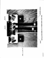
TRP 84OO D SERIES *
* NOTE. The technical manual for the
TRP 8400 series is based on the TRP 8250 D
series manual, with all deviations descreibed in the rear AMENDMENTS.
100
9-94
910 000 46
ISSUE A5
Skandi navisk Teleindustri A/S
34, Kirke Vaerloesevej - DK 3500 Vaerloese Denmark
AII information contained in this Manual lncluding att drawings, specifications, data or other
material, is the property of SKANDINAVISK TELEINDIISTRI SKANTI NS, ts disctosed in
confidence for use only ln operating and maintaining the equipment described herein, is
not to be copied and is not to be used or disclosed for any other purpose, without written
CONSENT OT SKANDINAVISK TELEINDUSTRI SKANTI NS.
Due to the constant processing of the experience gained during production and operation
of our equipment, minor moditications may occur retative to the information given in this
Manual. Whenever practicable corrections witt be listed on a correction sheet in the
Amendments chapter of this Manual.
@ COPYRIGHT 1986 SKANDINAVISK TELEINDUSTRI SKANTI A/S
.'''\
TRP
SOOO
TECHNICAL TRAINING COURSE
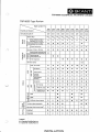
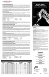
TRP 8000 Type Review
Type numbert)t)
TRP
Facility oi feature
Simplex/Duplex
3)
S/D
23ot
WATT PEP
t
From i-50.W lo'150 W
4$
fo
=L
!
o!
oO
:3
oo. T'O
oo,
.
(t
cct
ocD
fc
tt ro'
o!
lr-
?to
S/D
zSOt
,ts
s/D
230t
l7*
TRP
S/D
s/D
S/D
s/D
S/D
S/D
agttllD
2fi'
lzg
29t
l7n
250
7h)lr*
tto
o
o
c
o
belween1.6-4MHz
o
O
6
O
o
o
Overall reduction
o
o
o
o
o
o
o
o
o
o
o
a
o
a
c
o
e
e
o
o
o
o
o
c
o
G
o
o
I .rt
F;
Free freqyency
o
500 kHz lacility
oo)
USB, J3E A R3E
@
a
6
o
@
@
o')
o
@
Reception
0
o
e
o
c
6
I
o
&
.?
Transmission
o
o
o
o
6
I
e
o
e
ai
(/,
LSB-key
disabled
o
o
o
o
o
o
o
o
o
Transmlssion
disabled
o
o
o
e
o
o
o
o
o
Reception
o
o
o
o
a
e
o
o
o
Full range
o
o
o
o
a
o
o
o
o
2182 RHz only
c
o
o
o
o
o
o
a
o
Orsabled excepl
2182 kHr lrans.
o
o
o
o
o
o
o
a
o
ul
(r,
J
(/,
(1,
p
o
'J . .i
TRP
o
Marine bands.
free lrequency r)
a
TRP
o
Eo
6 l.t
(/)
TRP
From 750 W to 400 W
Marine bands,channels o/
iransmisslon lrequericies r
m
TRP
o
LN
OT
Cr
TRP
o
Receiver: 10 kHz - 30 MHz
r.)
TRP
o
between1.6-4MHz
E
\
TRP
8X50 8X51 8X52 8X53 8X54 8X55 BX56 8X57 8X58
LU
c
o
:E
2
(')
E
c
G
t:
o
=
o
CI
t(I'N,i<
AP
o
a
a
H2A
a
O
a
o
o
a
o
Two-tons alarm generalor
a
o
a
Alarmtest inlo dummy load t)
o
o
Enabled
a
Disabled
o
.o
N
A1A
F1B (incl. lelex filters).
C\'l
ol
,E
cc
6
(,
U'
],
o
a
o
a
o
o
o
O
a
a
a
o
a
a
o
o
o
o
o
o
o
o
o
o : Standard facilily/leature
O : Optional tacilily/leature
INSTALLATION
o
o
a
Legend:
\.
o
TRP
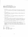
sO()O
TECHNICAL TRAININC COURSE
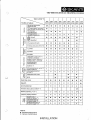
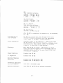
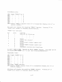
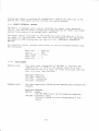
Type number')2
TRP
Facllity or feature
76 user-programmable
a.
o
o
TRP
TRP
TRP
TRP
TRP
TRP
o
o
o
G
o
o
e
c
o
o
ar
o
o
o'
o
o
o
pre.programmed
o
o
e
G
o
o
Pre-prog ram'rned
receplion_ lrequencies
o
o
o
o
o
o
o
o
G
o
c
c
c
o
c
e
o
'1017 pre.program, freq. pairs{)
(incl, ITU chan, in marinG vers.)
ITU channels,
EOr'
.E
tlt
TRP
o')
lrequency pairs
E
TRP
8X50 8Xs1 8X52 8X53 8X54 8X55 8Xs6 8Xs7 8X58
On/off
o
P6
(I)-
oo;
r:<
<6(, Slow/fast
g3
RF amplifiet (RF AMP)
s
0
0
O
o
0
6
Antenna altanualor (ANT ATI)
o
o
o
o
o
3
c
1.5 PPM
o
c
o
e
(t
o
o
o
0.8 PPM
o
o
o
o
o
o
ö
o
a
0.4 PPM
o
o
o
o
o
o
o
o
o
o
o
o
o
o
o
-o
o
o
o
L,|
o
o
o
o
o
o
o
o
o
>c
CI
o,
::.j
tr
o>,
c=
O=
:t
(t .o
ru
E6
ll'ia
o
l5O0-200O Hz lelex olfset
(17O0'fi2 is slandard)
=
'6,
Display of carrier frequency
(assigned treq. is standard)
o
o
o
Unallended telex
(AUTO-TELEX)ro)
o
o
o
o
o
o
MARITEX
ag
gx
o
F
o'E
C l^
c
-:)
@5F
:!:<
! cv
<5
F
o
q, .9
')
o
O
o
o
o
o
ATU with built-ln ant, swilch rr)
(built-in PCS 641).
o
o
o
o
o
o
o
o
Ant€nnä disconnected
o
o
o
o
o
o
o
o
in
'O)
lx-olf ')
SBlectable band widths
o
o
e
BFO
o
e
c
L=
'
e'6
4G
,')
u-
Realtime clock
o
o
o
o
a
a
a
a
o
Squelch
o
o
o
o
o
o
o
o
a
Line transformer
o
o
o
o
o
o
o
o
o
Aulomatic keying device (AKO)t?)
r.)
o
o'r)
o
o
o
o
o'.)
o
o
o
o
o
o
o
o
o
o
voll ot
24132voll balteryrr;
o
a
O
a
o
a
o
a
o
voll
o
o
o
o
o
o
o
o
o
o
o
o
o
o
o
13)
Fr€quency displays disabled
12124132
ää
06)
o
REMOTE CONTROL ro)
o-6
o
t3)
11Ol12QI22Ol24O
AC power supply
r'1
3x38O/3x220/3x440 volt
AC power supply') rc)
Legcnd:
I : Slandard facility/teature
O : Optional lacility/leature
INSTALLATION
o
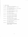
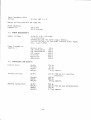
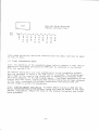
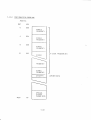
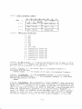
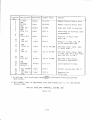
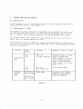
2.1
In
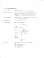
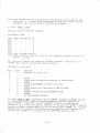
BASIC VERSIONS
common
:
258 lr/att p.t.p. pouer Amplifier.
Simplex/Semi-duplex operation 1.
640 fHz.
TRP 8250
S : Marine SSB Radiotelephone.
1017 preprogrammable frequencies in Marine Bands.
TRP 8251
S : Marine
SSB Radiotelephone.
Free frequency sel-ection Marine Bands.
TRP 8252
S : Marine SSB Radiotelephone.
Free lrequency selection Marine Bands.
CV,J
IRP B25J S
TRP 8254
TRP
MCtd
facilrties.
: Marine SSB Radiotelephone.
Free frequency selection all bands.
S : General Purpose SSB Radiotelephone.
Free frequency selection all bands.
8255 S
: General Purpose
SSB Radiotelephone.
Free frequency selectlon all bands.
Cid
TRP 8255
and
and
MCtd
facilities.
S : General Purpose SSB Radiotelephone.
Free frequency sefection all bands.
As type TRp 8254 S, but simplified keyboard.
IRP 8257 S
: l4arine SSB Radiotelephone.
Free frequency selectlon
Cln/ and MClr/ facilities.
TRP B25B
all
S : Marine SSB Radiotelephone.
bands.
Free f requency sel-ect j-on all bands.
Automatic reduction of pouer belou
4 l{Hz FCC version.
17
L- )
3.
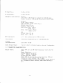
TECHNICAL DATA
Versions complying
are available,
and FTZ.
J.I
vith the S0LAS 74 convention and the ITU Radio Regulations
one or more of the specifications: CEpT, MpT, FCC, DOC
meet ing
GENERAL
Frequency Generation:
F
requency SeIect ion:
F
requenc y Presentat ion
F
requenc y
Ope
Stability:
rat inq modes:
True
digital frequency
synthesj_s.
By cornmon keyboard.
Single key selection of ZIB2 kHz
(rRp ezro s/825r 5/8252 5/8253 S).
75 user-programmable frequency pairs.
Scanning facilities (may be disabled).
Remote control ( optional ) .
:
Separate LED dlsplays
frequencies.
1.5
0.8
0.4
ppm
for recelve and transmit
(optional)
(optional)
ppm
ppm
Semiduplex and simplex.
JIE upper sideband, suppressed carrier.
!!9,
Rlt: Upper sideband, reduced carrier.
AM: HIE upper sideband, full carrier.
LSB: JiE loryer sideband, suppressed carrier
optional ) .
AIA morse telegraphy (TRp BZ52 3/8255 S).
H2A modulated morse telegraphy
TRP 8252 5/8255 S),
TELTX: FIB ruith center audio frequency selectable
betueen 1500 and 2500 Hz in 100 Hz steps
(
Ct/:
MCll/:
(
Operating Temperature
Range:
optional
*20 deg.
C
to
).
+55 deg.
Full
Performance
Temperature Range:
0 deg. C to +40 deg.
3-r
C
C
3.2
RECEIVER CHARACTERISTICS
Frequency Range:
100 kHz
(t0
t<ttz
to l0 MHz
to 100 kHz vith
reduced performance)
Frequency resofution:
100 Hz,by numerical frequency keyboard entry. A
search/fine tuning facllity is provided ruith selec_
table increment steps of 10 Hz, l00 Hz or 1 kHz.
In addition a user-programmed step size may be
selected.
Antenna Impedance:
Befou 4 MHz:
l0 ohm in series ruith 250 pF or 50
(std. ) internally selectable.
4
FlHz
to l0
MHz: 50
ohm
Input Protection:
l0
IF Selectivity:
SSB: 35O Hz Lo 2.1 kHz
V RMS (EMF)
AM:
for up to
15 min.
+/- 2.7 kHz or
+/- 4 kHz (optional)
Ct^J/MCt'J
(
rnp azrz s/8255 S):
lilide:
Inter:
+/+/+/+/-
2.J k1z or
4 k1z (optional)
r.2 k1z or
+/-
z>o Hz or
SgO Hz (optional)
+/-
ISO Hz
+/-
I5O Hz or
+/-
Narrou:
Ver y
Narrow:
2.1 kHz (opttonal)
(optional)
TELEX
(
optional
)
+/- zso Hz or
+/- 4oo Hz
Sensitivity:
Max. antenna
input
(EMF)
SSB
High impedance antenna:
7.6 - 4 FlHz: l-.2
uV
50 ohm antenna:
L6 - 3O l41z: 0.8
3-2
uV
for l0
dB
SINAD
ohm
AM
High impedance antenna:
100 kHz - 400 kHz: 60 uV
400 kHz - 1.6 MHz: 20 uV
I.5NlHz-4 MHz: 7uV
50 ohm antenna:
100 kHz - 400 kHz:
4O0 k\z - J0 MHz:
7uV
5uV
cw (+/- 5oo Hz)
High irnpedance antenna:
100 kHz - 400 kHz: 5.5 uV
4OOkHz- 4llHz:2
50 ohm antenna:
100 kHz - 3O l4{z: 0.6
l,r/hen RF-AMP
by 5
is
sef
dB.
uV
uV
ected, the sensiti-vity is increased
Intermodulation:
(out-of-band)
94 dBuV per signal- more than l0 kHz offset from
receiver frequency produces less than equivalent
input signal of l0 dBuV. (50 ohm antenna).
Cross modulation:
Unvanted signal of 105 dBuV/10 96 - 4OO Hz more than
2O kHz offset from rece_iver frequency, produces cross
modulation l-ess than -10 dB relative to a uanted
signal of 60 dBuV/SSB (10 ofrm antenna).
Blockrng:
More than B0 dB to cause a I dB change in output
po\uer vhen wanLed signal gives 20 dB SINAD, and the
unvanted signal is offset by more than 20 kHz from
the receiver frequency.
Image Rejection:
Greater than B0
IF Rejection:
Greater than B0 dB
Spurious Response
Rejection:
dB
Greater than B0 dB beloru 4 llHz
Greater than 70 dB above lr MHz
Internally generated
spurious signals:
Less than 5 dB SINAD (SSB)
Spurious Emission:
Less than 2O pW/5O ohm at antenna connector.
3-J
RF-Amplifier:
0 dB or I0
RF-Attenuator:
0 dB or 20 dB
dB
Automatic Gai-n Control_: Static:
Less than 5 dB change in ouLput for 100 dB input
signal variation from 20 dB sensitivity levef (SSB).
Dynamic:
70 dB signal change:
SSB, Ctd, MC\^i, TELEX ( fast
Attack time: 150 us
Debounce trme: l0 ms
Hold time: FasL: 100 ms
Slou: 2.5 s
Decay tlme: Fast: 400 ms
Sfour:
I.5
on
ly ) :
s
AM:
BFO
(optional):
Line output.:
I
Attack time: 150
time:
ms
Decay
ms
+/- I
kHz synthesized
100
in
100 Hz steps
Internally adjustable up to +10 dBm/500 ohm.
n-band
Intermodulation:
Audio Output
3.J
Pover:
Less than -50
dB
5 l/ in B ohm to internal and/or external loudspeaker.
TRANSMITTER CHARACTERISTICS
Output
Pouerz
250
[r,J
ohms.
PEP
+O/-I.4 dB from Transceiver Unit into
Pouer Reduction:
Medium: approx. 60 td P[P
Lov: approx. 10 td PEP
Single-tone max. Pourer:
50
25O W PtP for keying duty-cycle 1ess than 5596 and
modulation rates greater than I baud.
3 dB poruer reduction when continuously keyed during I
min. Automatic po\uer recovery uhen muted during 2
min.
J-4
Transmitter
Frequencies:
TRP B25O S:
to 1017 programmabfe
in the ranges:
1606.5 to lr800 kHz
6200 to B95O k1z
Up
channel-s,
freely distributed
I223O Lo Il55O kHz
18780 to 2]IOO k{z
TRP 8251 3/8252 Sl
Free frequency selection in I00 Hz steps in above
ranges.
rRP B25J 5/8254 3/8255 52
or programmable frequency
range:
1606.5 kHz to l0 MHz.
Free
Spurious
Alarm
Emissions:
Generator:
Audio Input
Level:
TRp BZ5O S/BZ5I 5/8252
Less than -4i dB/pEp
S:
IRP 8253 5/8254 5/8255
Less Lhan -62 d\/plp
S.
A tuo-tone al-arm generator is incorporated
(rnp szso s/Bz5r s/8252 s).
Telex: 0 dBm +10/_16
Aux:
Mic:
dB
Input impedance: 600 ohm
0 dBm +10/-16 dB
Input impedance: 500 ohm
20 mV Lo 2.5 V internally adjustable.
Input lmpedance: 100 kohn//6.8 nF.
Recommended
2.5 kohm.
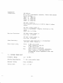
J.4
source impedance: Less than
ANTENNA TUNING UNIT
Frequency
Range:
1,6 -
Antenna
Requirements: 7 -
Antenna
Tuning:
Tuninq
time:
selection in the
3O
l_B m
NlHz
uire and/or vhip.
Fu1ly automalic
O.Z
- 1.5
sec
3-5
Input
Impedance
tuning:
after
50 ohm.
Manual setting possible
for
St^iR
(= 1.4
2IBZ kHz
Power Handling
Capabi.lity:
J.5
250 Id
PEP
1,25 W
Averaqe
POI^JER REQUIREMENTS
Supply
Voltage:
tZ-Z4-jZ V DC ( -IO/+1O\()
(no presetting)
Connection ruill not earth SuppJ-y Battery.
IIO/I2O/22O/24O V AC (optional external'pouer Supply
Unit, type P B25O)
Power Consumption
(approx. ):
Receive only:
JJE unmodulated:
HJE unmodulated:
HJE alarm:
Clr,/ keyed:
MCtd keyed:
ARQ-telex :
3.6
50 t^l
100
J60 W
420 W
540 l'il
420 W
3JO W
t/'J
DIMENSIONS AND I^JEIGHTS
Control Unit:
Transceiver Unit:
tdidth:
Height:
372
mn
87
mm
Depth:
ln/eight
201
mm
lnlidth:
422 nn (100 mm incl mounting
brackets ) .
Height
Depth:
[,r/eight
Antenna Tuning Unit:
4 kg, approx.
l5B mm
:
280
mm
26 kg, approx.
:
ll0
Il0
tdidth:
Height:
4lr0
Depth:
tn/eight:
mm
mm
(Sl5
mm
mm
5.7 kg, approx.
J-6
incl
antenna horn).
AC Poruer Supply
Unit (optional ) :
z
Height:
htidth
Z4t mm
36j nn (440 mm incl attachment
rails ) .
Depth:
l0l
mm
(tZt
mm
rai-1s ) .
17 kq, approx.
tr/eight:
J-7
incl
attachment
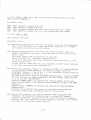
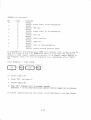
4.),.I2.I
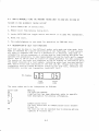
trtrtrElt-l
SECOND FUNCTION SYNTAX
(5)
Press "2tt.
The transmitter dlsplay is blanked and the decimal points start flashing.
The receiver display shous rr I rr 1o identify a non-standard display and
ttZtt. If ttZtt \uas pressed by mistake
"ENTER" will terminate second function
mode.
Press a number.
The number is passed to the receiver display. This number identifies the
second function page. If the number \vas pressed by mistake "ENTER" ruill
terminate second functlon mode.
Press a number.
The number is passed to the receiver dlsplay. Thts number identifies the
second function line. If lhe number \uas pressed by mistake "2" uill
restart- the second function mode.
Press
If
"ENTER".
page and line numbers are not varid lhe receiver display starts
flashing and the second funcLion mode can be either r""turted by pressing
"2" or terminated by pressing "ENTER". If both page and line numbers are
valid the respective second function is executed and if no further
keys
are required in the specific function the dj-splays are restored to the
st.ate prior to second function execution
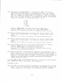
(5) Most second functions require additionally keys to be pressed.
Typicalry
"2" viff restart second function mode and "EN1ER" terminate it.
some second functions require confirmation via the "sT0" key. This
srtuati-on is indicated by a special uarning display-flash shifting between
"l]llJlJ" and the entered number. pressinn-"g1gi' rLrilr execute the
function, "2" rvill restart the second funötion mode and any other key urill
terminate it.
Second
functions requiring confirmation:
25Oz
25I:
27Bz
Clear
29Bz
Clear
RAM
Reset system
Clear "OPTI0N" register
280-287: Toggle "PRISET" register
"GUARD"
register
bit
0-7
4-r5
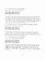
4'I'I2'2 PAGE 0 (20#) Self test. For detai]ed information see self test
descriptionTn.napter A.
Executable l-ines:
2BOz Start automatic st.epped self test.
201: Start manually stepped seli t.est..
2O2z Start automaLic stepped self test from an arbitrary test. number.
ZOJ: Start manually stepped self test from an arbitrary test number.
4.r.r2.i
PAGI
4
(24#)
Miscellaneous functions.
[xecutable ]ines:
24Iz Read accumulated on-time. Thg receiver display ruill show total operation
trme of the TRP 8250 S ruith t hour resolution. Pressing "2" or "ENTER"
ulll rest.art or terminate second function.
242: Read and proglam receiver tune step. The rece-iver display shorys the
present programmable tune step. A new tune st.ep may be entered via the
numeric keys.
Tune steps betueen 100 Hz and 99 kHz are possible.
Pressing "ENTER" ruill terminate second function.
To use this additional tune step,OPTION bil 4 should be set to I (ref.
second function 214).
In this case the "TUNE RATE" key vllr introduce a fourth stat.e indicated
by all tune rate annunclators switched off.
243: Read single frequency formats in configuration
is initiallzed to
PROM. The
reading address
0. The ieceiver drsplay shorLrs the
programmed frequency ii the RX bit
= l. The transmitter display shorys the
programmed frequency if the TX bit
= 1.
PR0M
address
The mode annunciators show the programmed modulation(s). pressing
"DIMMER
UP" urill increase the reading address to the next higher l-ocated format
if 1t is not the "LIMITER ByT[". '
Pressing ''DIMMER D0l'ilN" urill decrease the reading address to lhe next
louer l-ocat.ed format if the present reading addiess is higher than pRgM
address 0.
Keeping either "DIMMIR" key pressed rui]1 advance the reading address
automatically.
Pressing "2" or "ENTER" rvill restart or terminate second function.
For further PR0M format information refer to section 4.1-0.
2442 ConLrol BFO frequency. The receiver display shovs the presenL BFO
frequency. The transmitter display shous the stored BF0 frequency
selected on po\l/er-up. Pressi,ng "ST0" rLrill store the present f requency.
Pressing "RCL" rvill recall the stored frequency. Pressinq ttztt or "ENTER"
urill restarL or terminate second function.
4-16
245: Read special system parameters in configuration pROM. The receiver
display shous the PR0M address in decimäl initialized to top of pROM
4095. The transmitter display shous the PR0M data in declmal. pressing=
rrRCL'will change the displayed data to hexadecimal,
useful ruhen reading
BCD. Since the display decoder is not. designed for letters the foltoyin!
symbols are displayed for hexadecimals greäter than 9:
A
B
C
D
E
F
f
f
LJ
E
tblank
Pressing "DIMMER DOh/N" ruill shoru the next lourer pR0M address.
Pressing "DIMMER uP" urrll shorv the next hlgher pRBM address.
Pressing rr2rr or "ENTIR" ruill restart or terminate second function.
246: Read CU program release date and version. The receiver display shorys
release dat-e (year,/month/day). The transmitter display shorus version
number.
Pressing "2"
or
"ENTER"
rurll restart or terminate
second function.
2472 Read TU program release date and version. The receiver display shows
release date (year/monLh/day). The transmltter display shovs version
number.
Pressing "2" or "ENTER" will restart or termjnate second function.
248: Adjust beeper sound level. A continuous control beeprng rs started.
Pressing "VOLUME UP" ruill increase the sound 1evel.
Pressrng "VOLUMt D0[dN" wil] decrease the sound levef.
Pressing "2" or "ENTER" rvill restart or terminate second function
preserving the new beeper sound level.
249: Sruitch antenna OFF. The antenna and transmitLer are suitched OFF. The
po\uer annuncj"ators are turned OFF to identify antenna 0FF and transmitter
di-sp1ay shows time of day to identify transmitter OFF. Flnally second
function is terminated. ldhen "TX 0N/0fF" j-s then pressed both antenna and
transmitter are srvitched 0N and po\uer annunciators and transmitter
display restored to normal.
4.I.I2.4
5 (Z5ll) Misceil_aneous flunctions. This page can not be entered
biT 7 is set (see second function page 9).
PAGI
rLrhen "GUARDU
Executable lines:
25O: Clear RAM. The function requires confirmation as described for the syntax
kuy (5). Al-1 stored frequency parrs and modes, the "OPTI0Nt'register and
"GUARD" register uill be cfeared (=0) and second function terminated.
4-r1
25I:
Reset system. The function requires confirmation as described for the
syntax k"y (r). J2 msec af,ter releasing the "sTO" key, both cu and TU
processors are reset by running the pou/er-up program.
4.t .12.5
PAGE
1 (2t#)
Controls an B-bit "0PTI0N" register.
Executable -lines:
27Oz Toggle "OPTION"
?11
.
bit
,10.
LIL.
_J
ZlJ:
21 4z
0
I
a
L
/t
-5
27 6z
6
211:
1
2lBz Clear "0PTI0N" register
279: Display "0PTI0N" register (Oits 0-l in transmiLter display, bits 4-7 in
receiver display ) .
All
I j-nes
"fNTER"
r'0PTI0N,
BIT
0
t2j
40
50
60
70
rui1l drsplay the resuJ-tinq
ruill restart or terminate
"0PT
I0N" register. pressing "2" or
second function.
bit functions:
LTVEL
O
I
I
I
I
FUNCTION
Reserved
Normal
Enable special squelched scanning
No
rmal
in
"phone mode"
Enable programmabl-e receiver tune rate
Normal
Enable phone
Norma
I
call interrupts in
MARIIEX mode
Disable'TENTER" key during MARITEX
Norma
1
for future use
No
l
mode
time-display "cursor"
4.I.I2.6 PAGE B (28#) Controls an I bit ''PRESET, register intended for use
in installätron only. Special system parameters rLrhich are difficult to
specify before installation can be changed on location by toggting the
respective bit 1n this non-volatile register. To protect the npRESET" register
against erloneous changes Page B can not be entered ruhen "GUARD" bj-t 7 is set.
Toggling any bit requires confirmation as descrrbed for Lhe syntax key (f).
Further more "PRfsET" is excfuded from the cLtAR RAM functi_on ( 25ü.
4-1
B
Executable fines:
280: Toggle "PRESET" bit
0
282
2
283
284
285
3
28I
L
286
j
2Bl:
289: Display t'PRES[T" register (bits 0-l in transmitter display, bit 4-7 in
rece_iver display ) .
Al1 lines ruil1 display the resulting "pRESET" register.
"fNTER" ruill restart or terminate second functi-on.
'TPRESET"
blt functions:
BIT
LTVEL
FUNC T
I
ON
Reserved
0
Pressing rt2rr or
for future use
t-
2
J
4
5
6
;
I
No rma
0
Normal
1
Disable po\uer display (ampere only)
c
Disable ampere display (poruer only)
Normal
Complement
0
I
4'I'I2'7
PAGE
inhiblt"
Normal
I
1
l
Enable "Key
exLernal scan transj-tions
9 (29t1) Controls an B-bit "GUARD" register. This page can not
bit 7 is set (see foiforrnq 6xptaÄat:.on).
be entered \u6enrrCf;IRD"
Executable lines:
29Oz Togqle "GUARD"
29Iz
292:
293
bit
-1
-2
0
z
294t
295 t
296:
297
z
298: Clear "GUARD" regisLer.
299: Display "GUARD" register (Oits 0-l in transmitter display, bit 4-7 in
receiver display ) .
All lines will display the resulting "GUARD" register.
"ENTER" ruill restart or terminate second functlon.
4-19
Pressing tt2t' ot
"GUARD"
BIT
0
bit flunctions:
LTVEL
0
1
0
I
O
I
O
I
0
I
0
I
O
I
O
I
I
2
3
4
5
6
1
FUNCTION
Normal
Inhiblt drrect entry of, RX frequencies
Normaf
Inhibit "RX" key
Normal
Inhibit direct entry of
TX frequencies
Normal
Inhibit "TX" key
Inhiblt store function
Normal-
Normal
Inhiblt "ST0"
key
Normal
Inhibit entry of scan
parameters
Normal
Inhibit certain
second
lunction
pages
prggrammed in Lhe configuration pROM (ref.
5.rz), either of the RX
Jf
(bit 0 & 1) and TX (biL 2-3) GUARD bits set tosection
I vil] cause the respective
display to show channef numbers exclusively. If no channel- number applies to
the frequency then a rrCrr ruilt be disptayed (".g. immediately after "SUppLy
0N".
Clear GUARD-bit 7 (pnCt
GUARD)
(1)
(
1) Sruitch supply OFF.
2 Press "RCLrr and keep it.
I
Sruitch supply
4
Keep rrRCLrr pressed
Guard-bit 7 is
0N.
noru
until the beeper sounds.
cleared and all second function
To prevent unauthorized use
pages can be entered.
thrs syntax is not described in the
4-20
User ManuaL.
4.1.12.8
Start
Start
Start
Start
200:
20I:
202l.
2O3z
24\z
242:
243:
245:
2462
247:
248:
249:
Clear
250:
25r:
RAM
Reset system
270-271
:
2BO-2BI
Toggle "0PTI0N" register
bit
0-7
Toggle "PRESET" register
bit
0-7
Clear "OPTI0N" register
Read "0PTI0N" register
z
219:
z
289:
Read "PRISET"
29O-2962 l
)q1
automatically stepped self test
manually stepped self test
automatic stepped self test from an arbitrary test number.
manually stepped self test from an arbitrary test number.
Read accumul-ated on-time
Read and program receiver tune step
Read single frequency formats
Control BFO frequency
Read special system parameters
Read CU release date and vers_ion
Read TU refease date and version
Adjust beeper sound fevef
Turn OFF antenna
2442
278
SECOND FUNCTIONS SUMMARY
.
oggle
register bit
register bit 7
"GUARD"
Set. "GUARD"
29Bz
Clear
299
Read "GUARD"
z
4.2
register
0-d
register
register
"GUARD"
DESCR]PTION
OPERATING CONTROLS
OF
@
Sruitches 0N/0FF the equipment pouer supply. When sruitched
the equipment enters the state it ruas in just before
being sryitched OFF.
f-r.r
suritches 0N/0rF the transmitter functions. The transmilter
dispray shows the transmitter frequency uhen switched 0N,
and the time of day when sruitched OFF.
0N
l*ll-";l
Increases and decreases the Iight intensity in
the displays, meters and annunöiators
4-27
Storing of receiver/transmitter frequency pairs and mode.
is pressed the receiver and transmitter displays
are blanked and their decimal points start flashing, indicating that a channef number (O-lS) must be entered in the
recej-ver display via the numeric keys.
lr/hen "sTO"
setting/recalling
scanni,ng parameters and
start/stop
scan-
ning of st.ored receiver,/transmitter frequency pairs. The
annunciator is flashing in automatic scanning mode and
turned constantl-y 0N i-n manuaf scanning mode. (for details
see section ll. l- )
Settrng time of day, setting/recalling vake-up time, star_
ting dormant state and setting drLrell [ime in scanniÄg. (for
details see section 4.1)
Pressrng "DUPLEX" causes no acLion
in the
TRp 8250
S
function: Change of receiver frequency. h/hen
is pressed the receiver display is blanked and its
decimal point starts fIashing, indicatinq that a ne\y
receiver frequency must be entered into the display via
the numerrc keys.
Secondary function: Setting of uake-up time, uhen "RX"
is pressed immediately after "SET TIME". Opening of the
external- scan port (see section 4.1)
a) Primary
"RX'r
b)
a)
b)
function: change of transmitter frequency. lr/hen
flimary
pressed
is
the transmitter display is blanked and
'rTX"
its decimal points starts flashing, indicating t.hat a
neu transmitter frequency must be entered into the display via the numeric keys.
secondary lunction: Recalling of transmrtter frequency
from PROM. Closing of the external_ scan control port
(see section 4.1)
4-22
function: Recarling stored recei-ver,/ transmitter
requencles. l,l/hen "RCL il is pressed the receiver and
transmitter displays are blanked and t.heir decimal
points start flashing, indicat.ing that a channel-number
ß-l>) must be entered into the ieceiver display via the
numer j-c keys.
b) Secondary function: Recalling vake-up time, when 'rRCLil
is pressed immediately after "SET TIME" and recalling
scanning parameters vhen "RCL'r is pressed immediately
after "SCAN" (see sectlon 4.1)
a) Primary
f
Numeric kevs
a) Primary functions:
Entering of receiver,/transmitter
b)
cies and channe]
frequen_
numbers.
Secondary functlons:
Setting scanning parameters, time of day,
time and sound level of beeper.
Refer to section 4.1 for further details.
wake up
rGl
EE
Terminating keyboard operation. "ENTER" must be pressed to
terminate alI keyboard operations initiated by the "RX",
"TX", t'ST0", "RCL", "SCAN", "SET TIMEil or numeric keys.
Generally the displays rurrl then be reset to their initial
states if the operating parameters are va1id. An exception
is the self test mode ( see section 7.4)
Adjustment of receiver AF-amplifier gain.
(Sound level of internal speaker, haÄdset
phone and headphone). Pressing one of the keys
turns on the corresponding annunciator, ruhich
is turned off again ruhen the key is released
or uhen minimum or maximum sound level is
reached.
Adjustment of receiver IF-amplifier gain
the AGC :-s sultched OFF.
4-23
urhen
trtr
Switches 0N/0FF the AGC (Automatic Gain Control). The an_
nunci-ators indicate rvhether the AGC is 0N or OFF. tnjhen the
AGC is 0N the receiver iF-amplifier gain is automatically
adjusted and manual control disabled. l.dhen the AGC is sryitched OFF the receiver IF-amplifier gain is maintained on
the level it had just before the AGC rvas svitched OFF and
manuaf control vra the "sfNSITIVITy" keys is enabled. h/hen
seJ-ecting a ne\u receiver frequency the AGC should alruays be
0N' to ensure that. a suitable starL levef of IF-amplifier
gain is set before the AGC is srvitched OFF for manuaf adj ustment
trtr
.
selects AGC time constant, that is the rate at which gain
is regulated. Annunciators indicate vhether "AGC sL0v,/il or
"AGC FAST, is selected. "AGC sL0b/'r is automatically sefected rvhen switching to the modes ssB, RIE or MCtd. "AGC FAST"
is automatically sefected vhen suritchrng to the modes AM,
TELIX or Ch/. The settings selected by the system are as_
sumed to give the best- reception in the modes concerned but
under special circumslances a better reception might be
obtained by pressing "AGC FAST " r f "AGC sL0!,J" uere selected
and vice versa. In the AM and the TELEX-mode onlv "AGC
FAST"
is possible.
Svitches 0N/0Ff i-nternal and external loudspeaker. Annunci_
0N i,ndicates loudspeaker(s) 0N. If headphones are
connected via the socket on the rear of the control unit,
the internal loudspeaker is alvays svitched 0FF.
ator
Increases receiver gain 10 dB by actrvating the RF-amplifier stage. Annunciator 0N indicates RF-amfilifier 0N. The
RF-amplifier may be used vhen the received siqnal is weak.
receiver gain 20 dB by inserting the antenna
input attenuator. Annunciator 0N indicates attenuator 0N.
The antenna attenuator may be used if the received srgnar
is disturbed by strong out-of-band signals.
Decreases
srvitches 0N/0FF squelch function. Annunciator 0N indicates
Squelch 0N. If the Squelch is 0N a speech signal ruith a
signal to noise ratio greater than a cert.ain value i-s required to pass the signal through the receiver AF_ampli_
fier. The squelch i-s used to eliminate noise when there is
no speech signal on the receiver i""qr"n"y. The Squelch
Board ts optional. ia/hen not installed, pressing the key
causes no act.ion.
4-24
rE
sel-ects frequency sLep in receiver tuning. An annunciator
belou one of the three rlght hand diqits of the receiver
display indicates the frequency step select.ed. l0 Hz, 100
Hz and 1000 Hz st.eps are posslble.
Tuning of receiver frequency up or dovn in frequency
steps sefected by the "TUNE RATE" key (see section
4.1)
ET
Adjustment of the BfO frequency down and up in Ctn/
mode. Receiver display shows BF0 frequency vhen
either of the keys are pressed.
tr@tr@
Selects respecti-ve IF filters in
MCtl/
mode. Annunciator 0N
filter.
Cl,rJ
and
indicates selected
Selectrng transmission of JIE and reception of JIE and Rl[
signals in USB (Upper Side Band). Annunciator 0N indicates
USB-mode sefected.
Selecting transmission of JIE and reception of JIE and RIE
srgnals in LSB ( Loryer Side Band ) . Annunciator 0N indicates
LSB-mode selected. If transmission of LSB is illegal and
transmitter is 0N, the transmitter display is flashing and
transmitter function disabled.
Selecting transmission of HIE (Upper Side Band) and recepHIE and A3E signals. Annunciator 0N indicates AM
mode sel-ected. If transmission of HIE is illegal and transmitter is 0N, the transmitter display is flashing and
transmilter function disabled.
tion of
Selecting transmission of RIE and reception of RIE and JIE
signals (Upper Side Band). Annunciator 0N indicates RIE
mode sel"ected.
4-25
seJ-ecting transmission and reception of Telex in FrB mode.
Annunciator 0N indrcates Tefex mode sefected. The Telex
function is optional.
Fast set up for 2rBZ kHz. pressing this key vi11 instanLly
change rece-iver and t.ransmitter fiequency Lo 2IBZ kHz,
se]ect AM (UJI) mode, select FULL p0filtR, and enable trans_
mltter function (TX 0N). The loudspeaker(s) and AGC are
automatically sruitched 0N and RF-AMp, ANT ATT and sQUELCH
srLri-tched OFF. Antenna current rs displayed uihen transmit-
tlng.
Fast set-up for 500 kHz. pressing this key ruirl instantry
change receiver frequency to 500 kHz and select MCt^/ (H2Ai
1ode. The loudspeaker(s) and AGc are automatically srLritched
0N and RFAMP, ANT ATT and SQUTLCH switched OFF. If FILTIR
keys are enabled and the intermediate type fi-rter automatlcally selected.
selecting transmission and reception of AIA morse telegraphy srgnals. Annunciator 0N indicates cw-mode selected.
If transmission of AIA is ilregal and transmission is 0N,
the transmitter display is flashing and transmrtter functron disabled. IF FILTER keys are enabled and the rntermediate type filter automatically selecLed. BF0 rs enabled
and AGC rs srLritched 0N.
selecting transmission and reception of H2A modulated morse
telegraphy signals. Annunciator 0N indicates Mc\rj-mode selected. Il transmission ol H2A is illegal and transmission
is 0N, the transmitter display rs frasÄing and transmitter
dlsabled. IF FILTER keys are enabled and Ihe intermedi-ate
type filter automaticarly serected. AGC rs suitched 0N.
Activating Antenna Tuner. pressing this key ruill start the
automatrc tuning procedure in the-ATU (Antänna Tuning
unit). Tunrng is performed in ress than r.5 sec. pressing
the handset key for the first time after changi-ng transmitter frequency ruil1 also start the tuning p.o"6drru, and i-L
is therefore not necessary to press ,'TX TUNE" in this case.
t'TX TUNE" is normally used rvhen the
frequency has been
unchanged for some time and t.he antenna impedance has
changed due to external circumstances (see section 4.1).
selecting l-ow transmitter output po\uer ( approx. l0 ld ptp ) .
Annunciator 0N indicates L0t^J p0t/ilER sefected.
4-26
Selecting medium transmitter output po\uer (approx. 50
PEP). Annunciator 0N indlcates M[DIUM POh/ER select.ed.
Select.ing full transmitter output po\yer (approx. 25O W
PEP ) . Annunciator 0N indicates FULL P0llJER selected.
Testing and transmj-tting t.he tryo-tone al-arm signal. Press
"STOP ALARM" and the left key simultaneously and keep
pressed to test al-arm. The alarm signal rs heard in the
loudspeaker, and t.ransmiLter keying is disabled. If the
Dummy Load optlon is installed the alarm generator and
the transmitter is lested on the buj-lt-in dummy load of
t.he Antenna Tuning Unit. The Antenna Current Meter indicates current into the dummy load. The 0utput Por;er and
Antenna Current. annunciators are flashing to shoru that
the transmitter is tn the test mode. Test on dummy load
cannot be performed on 2IBZ kHz.
Press the
left
and
right keys simuftaneously to
send
alarm. The al-arm signal is heard in the loudspeaker and
transmitted for 45 sec. on the selected frequency if the
transmitter is 0N. The alarm signal may be interrupted by
pressing "STOP ALARM".
4.2.I Transmitter Displav In its initial state the transmitter di-sp1ay shorLrs
thetra@inkHzifTXis0Northetimeofdayinhoursand
minutes if TX is OFF. Trme of day is indicated by a flashing time cursor (lrC
drgi-t). A steady time cursor indicates that entering or recafling of time has
not yet been terminated. A flashing decimal point indicates t.hat enterlng,
storing or recalling of a transmitter frequency has not yet been terminated.
Flashing digits indicate that the transmitter frequency and,/or mode is
unauthorized, i.e. the frequency is outsrde the specified range and/or not
contained in the frequency PR0M. The transmitter cannot be keyed if the
t.ransmitter display l-s f lashing.
4.2.2 Receiver Displav In its initial state the receiver dlsplay shorus the
receiver frequency in kHz. A flashing decimal point indicates that. entering,
storing or reca}l-ing of a receiver frequency or channef-number has not yet
been terminated. Flashj-ng digits indrcate that the frequency or channelnumber is outside the specifred range.
4-21
4'2.3 ,-Siqnal Strenqth metgr Gives a relative indication of the signal
strength in the received signal.
t"t Measures the antenna currenr
f;2'a9ulqgt_9o*g:fnllSnt
transmi-ssionon21B2kHz@indicatedbytheantennacurrent
durins
annunclator. Gives a relatlve indication of the transmitter output po\rer
during trans- mission on other frequencies by measuring the output peak
voltage/current, as indlcated by the output po\yer annunciator. A flashing
meter indicates a fault in the Transceiver Unit - Antenna Tuning Unit
communication.
Output pouer annunciator Also serves as a mlsmatch indicator on all1.2.5
trequencres. If the input StrJR of the Antenna Tuning Unit exceeds l:l the
output po\uer annunciator starts flashing, indicatiÄg thaL tuning is required.
Reduced po\uer annunc-iator If the temperature of the pouer Amplifier
!.2:6
heatsinkgUnitexceedsthe1rmaximum1eve]-s,t'he
output po\uer is reduced by 5 dB ryhich is indrcated by the reduced pover
annunciator. This may occur due to extreme environmental and/or working
conditions.
4-28
q
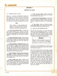
INSTALLAT ION
Correct installation of the equipment is important lor maximum performance and
reliabllity. Antennas and earth connections must be installed vith the
greatest care using corrosion resistant materials. Cable routing shall be made
so the cables are protected from physical damage. Cable bends eipecially on
coaxial cables may not be sharp and a sufficient number of clips or straps
should be used for securing the cables. Before installing the equipment make
sure that the Configuration PR0M is properly programmed, Äee sectron 5.12.
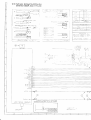
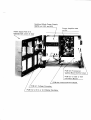
5.1
Mounting the Control Unit
The Control Unit can be tabletop or bulkhead mounted. Fig.5.l shorys overall
dimensions and a drilling plan for the necessary holes. The unit rs bolted
throuqh twc holes on Lhe bottom part of the cabinet. The unit must be opened
uhen bolting. Loosen the trvo f ront panel scre\r/s and lif t of f the f ront panel .
The iront panel- is hinged to the boLtom part by means of tryo flexible straps.
To enabfe cabfe entry from either slde of the unit, the bott.om part of t.he
cabrnet may bre turned 180 deqrees relative to the front panel. To alt.er the
position' open the unit and loosen the scre\ys of the hinges in the bott.om part
of the cabinet and release the hinges. Turn the front paneJ, and fix the hinqes
in the opposite srde of the cabinet bottom. Be careful not to damage any
components or to drop any conduct-ing objects onto the printed crrcurt boards
of the unit. The front panel can be t.ilted for convenlenL operation. To
adjust the angle l-oosen the truo front panel screu/s and open the unit. Move Lhe
tuo stop pins in each slde of the unit to the appropriate holes and refit. t.he
front panel,
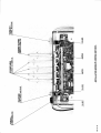
5.2
Mounting
the Transceiver Unit
The Transceiver Unit may be mounted up to 100 metres from the Control Unit
uslng a screened l5 x 0.5 mm sq. multiruire cable for interconnection. The unit
should be installed in a dry place and consideration should be given to
accessibility for servicing. The brackets supplied allou for bulkhead or bench
mounting. Fig. 5.2 shotvs mounting details. It j-s important to provide plenty
of airspace belov and above the unit, for adequate air circulation through the
heatsink at the back of the uni.t.
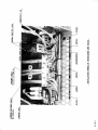
5,3
Mounting the Antenna Tuning Unit
The Antenna Tuning Unit may be mounted up to 100 metres from the Transceiver
Unit using RG-ZI3/U (RG-BA/U) coaxial cable and a screened 16 x 0.5 mm sq.
multirvire cab]e for interconnection. The unit should be installed near the
antenna feed point. Fig. 5.J shorys mount:-nq details.
5-1
5.4
Power Supply
The TRP 8250 S operales at voltages betveen 10.5 and 4l.d VDC and is
to be
powered from a 12, 24 rst J2 volL-f:attery or from a separat.e
AC power Supply
Unit' The supply leads are connected to the Transceiver Unil throuqh the cable
entry at the rear of the cabrnet. The supply terminal strip is adapted for
screened po\uer supply cable as required by some administrations. The screen of
the cable is connected to Lhe center terminal. The termrnal strip may be
removed from the chassis for easier access. Attention shoufd be paid to
Rec.2lB-1 rlhich recommends that cables in the vicinity of the receivi-ng CCIR
antennas or the radio receiving room, and cabfes ryithin the radio room, are
screened by encloslng them in metal conduits, unless the cables
are
effectively screened. The earth connection of the equipment willthemselves
not
cause
the battery to be earthed. Maximum permissible peak vollage betueen the
battery terminals and earth is 100 V. Note thal fuses rrJt b" provided in the
supply leads. Installation diagram fig. 5.J shorus the necessary cable cross
sections and ext.ernal fuse ratings.
5.5 Earth
Connections
5'5'1 Antenna r-Urr:-tq-Urr:!- As the earth connection of
ofthe@,itisoftheutmostrmportanceLhattheearth a transmitter is part
connecLion to the Antenna Tuning Unit is constructed to have the louest
possible RF-impedance. Losses in the earth connection uill result in a
decrease in radlated pouer rvhich means that the range of the transmitter ryill
be reduced. In steel ships a 50 x 0.5 mm copper strap as short as possible
j-s
connected betueen the earth terminal at the bottom of the Antenna Tuning Unit
and trvo l/2" or M12 bolts rvelded to the superstructure. Vessels constructed
of non-conducting materiafs must be equipped ruith a copper earth plate
havi-ng
a minimum alea of I square metre mounted belou the uater l:-ne. From a copper
earth bolt hard soldered to the earth plate a 50 x 0.5 mm copper strap is'run,
preferably uninterrupted to the earth terminal at the botlom of the Antenna
Tuning Unit. Should it be necessary to break the copper strap, for example to
pass through a deck, L\uo I/2,'or Ml2 botts should be used for'ihrs feed
through. The copper st.rap may not be passed through rron prpes and should be
kept at minimum distance of 0.5 m from lron parts oi some extent. If this
minimum distance cannot be kept the copper strap must be effectively connected
to these parts using a strap having the same dimens-ions. 0n vooden ships
havinq a superstructure of metar, thrs superstructure should also be
effectively connected to the copper strap by using stainless steel bolts and
preferably pieces of stainless steer strrps betryeÄn the metal parts.
5 '5 '2 0ther Unlts All other units must be grounded
separately to the ships
metal i;-thtshortest pcssible ruay. The Contiol Unit is connected to ground
from the ground frame at the cable entrj-es using a 2.5 mm sq. uire. In the
Transceiver Unrt a ground strap is connected to t.he ground lermi-nal at. the
cable ent'ry. 0n vessefs ruit.h no metallic superstru"Iu"" the ground connection
at the control unit and the Transce-iver unit may be omitted.
q.,
5.6
Antennas
The standard equipment is used ruith separate transmitting and receiving
antennas. If, however, the Antenna Tuning Unit is fitted ryith the optiönal
Antenna Relay Boardl-6dla common antenna may be used for transmission and
reception. The antennas should be erected ruell in the clear, a\ray from any
objects uhose influence on the anLenna may vary, such as derricks etc.
Insulators should be of the best type having lour J-eakage even uhen uet. Stays,
uires, steel masts etc. should be erther effectively earthed or insulated.
The receiving antenna shoufd be kept as far as possible from electrical
equi-pment in order to minimize noise. Ifectrica] installation such as cable
braiding (screens) and instruments in the vicinity of the receiving antenna
should be earthed effectively, and the instruments in question shoJlO be
fitted rvrth noise-interfetence suppression devices, effective in the range 0.1
MHz
to
3O l{Hz.
.6.r Transmitter Antenna The Antenna Tunj-ng Unit will tune on any frequency
in the range 1.6 to l0 MHz to uire and/or rvhip antennas of 7 to lB metres
total 1engt.h. A long antenna is pref erable ruith regard to radiated pover.
5
The antenna is terminated at the j-nsulator at t.he top of the Antenna Tuning
The insulator must be relieved from mechanical stress by using max. i
metre flexible uire betueen Lhe insulalor and a support.
Unit.
5.6.2 Receiver Antenna Lengt.h: 7-3O n. The antenna feed-rn should be coaxial
cab1e.ffiennatermina1isaUHF-connector(PL25glvp")1;;;l;Jin the Transceiver Unrt.
If a long cable ls used an "impedance matching transformer shoufd be inserted
at the antenna end of the feeder. In one antenna installations using the
optional Antenna Relay Boardl-6dlthis lransformer is built-in.
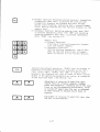
The receiver is normally delivered to 50 ohms input impedance. In the
frequency range belov 4 NlHz it is possible to change the input to high
impedance, ruhich can be advantageous uhen using a short receiving antenna ryith
no rmpedance matching transformer and a short feed-in.
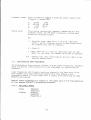
Selection of high input impedance in the range belory 4 l4Hz is carried out, by
of a soldering iron, by moving the strap from L to H in the desired
frequency range. Belov figure shovs a section of PCB@]with all straps set
to lou impedance (50 ofrms).
means
5-J
(4O5 kHz
I.6-4
t41z
521-I5OO k{z
4O5-527
k{z
5.1 Interconnection of Units
5.7.I Control Unit-to-Transceiver Unit connections The units are
rnterconnected by a length of 15 x 0.5 mm sq. screened multiryire cable
100 metres
(max.
).
In order to connect the cable to the Control Unit the front panel is
removed.
The cable is entered through lhe threaded cable entry and th'e uires are then
connected to the terminaf strip marked 501T52 Transceiver Unit. N0TE: Idire
ends should be f,itted with cable end sleeves before mounting. The screen is
connected to the ground frame at the cable entry. To connect the cable to the
Transceiver Unit the front. must be opened. The cable is entered through the
cable entry at the back of the unit and the uires are connected to the
terminaf strip marked 620I33 Control Unj,t. The screen must be connected to the
chassis bracket. For connections see installation diagram fig. 5.j.
.2 Transceiver Unit-to-Antenna TuJrinq Unit connections The units are
interco
iä', 0.5 mm sq.
screened multivire cable (max. 100 nletres). In one_antenna installations using
the optional Antenna Relay BoardlffiJan additional RG-213/tJ coaxial cable is
5.7
used.
The
coaxial cables are terminated in UHF-connectors (pL Z5g Lype). The sockets
may be removed from the chassis for eä'si-er access.
in the Transceiver Unit
The multiuire cable is mounted in the same ruay in the Transceiver Unit as the
cable from the Control Uni,t. The uires are connected to the terminal strip
marked 520TSl Antenna Tunrng Unit, see fig . 5.3.
5-4
If the TRP BZ50 S is not operated ruith an ATU 8250 Antenna Tuning Unit a
strap must be placed betueen term_inal no. 5 ( TUNE) and terminal
no. 7 (TpR) of
620T51. A missing strap ryill cause the pover Meter display to flash ll sec.
after a TUNE sequence has been initiated.
NOTE:
The cables enter
the Antenna Tuning Unit through the threaded cable entries
the bottom of the unit. The wires must be conn6cted as shovn in fig. 5.3. Theat
screen of t.he multivire cable must be connected to the receptacle at the
grounding tab next to the termlnaf strip.
N0TE: bJire ends
bef,ore mounting.
of the multirvrre cable should be fitted ruith cable
end sleeves
In installations uith long earth straps to the Antenna Tunrng Unit, high RF
the ATU ground terminal. To avord this voltäqe
being coupled to the Transceiver Unit the interconnection cab]es must be run
from the Transceiver Unit to the point uhere the copper strap from the Antenna
Tuning Unit is connected to earth. From this point the cab]-es must f,o1lory the
copper strap to the Ant.enna Tuning Unit. The cables should be placed upon the
center of the copper strap to ensure good coupling. The part oi tn" cabfe-run
betveen earth and the Transceiver Unit must not bö run rn parallel rvith the
earth strap vithin a distance of, at least I metre.
5.8 Connection of External fquipment
voJ-tages may be present on
Auxiliary terminafs in the Control Unit and the Fransceiver Unit allows
varj-ous external equipment to be connected to the TRp 8250 S. In tables 5.2
and 5.5 terminal assignments are listed for the Control Unit and the
Transceiver Unit respectiveJ-y. Screened cable should be used ruith the screen
connected to ground frame or chassis.
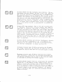
5.8.1 Timinq of-TELIX KEY siqnal The transmitter pre-keying time should be
approx. 7 ms. not less. Telex modems ruith programmabl-e pre-keying time must be
programmed to this val-ue. In case of telex modems ruith a flxed pie-keying time
longer than 7 E:_a time delay may be introduced by the TELTX xLv orlnv
circuit on PCB|ffi|in
the Control Unit.
The leading edge of the TTLEX KEy signal may be delayed by up to l0 ms. in
steps of l.ll ms. by moving a strap to the appropriate position.
trtr
TELEX KTY DILAY SILECTION
( factory setting: 0 ms.
)
TPl
IP2
\o
!U
a
E
O
Telex
modem
-EE
lf\
\O
l'^r \O
n\O
clo
aa
n\O
v\
AOO
aaa
9
Cf
-t
{a
M\\OO
r.a \o
--i
-l
N
NC\
O
E
cl
\o
tr\
pre-keying time minus selected telex key delay time must be equal
to 7 ms. or more.
5.9 Final Instal"lation
Check
5.9.I For operation of the equipment please refer to chapter
Note that
appropriate programmed Configuration pROM must be installed inJ.the
Control
Unit, see section 5.12.
an
Unit will tune aut.omatically to the transmitter anlenna
is keyed or the TUNE but.ton is pressed. The standing uave
ratio (St^/R) at the input of the tuning unit is autämatically
measured after
the tuning sequence. If the StdR exceeä"
pourer Annunciator on the
I
the
Control Unj-t vill flash, indicating that"ppro*.
correct
has not been obtained.
In this case' investigate the anteÄna installationtuning
and control that the
antenna length is ruithin the boundaries.
The Antenna Tuning
when the equipment
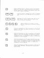
?19? kHz Manual Tune set-up To enabre manuaf
?^.^?.2,
Manua].TuninaTuningunitmustb;ö.;;"Ionthefina]
antenna installation. Remove the cover
beloru procedure.
tuning on 2rB2 kHz the
of tÄe Antenna Tuning Unit and f,oI1oru
5-6
P
E
i:>:>>
i{d?<<<<
>:
33333333
TUNE SETUP
INDICATORS
FiUi'UUU:
e;>rr)r:
9oÖooooÄ
löööooodd
6ö00öö0öl
-TTTTTT._
'--frr-T]rrllti
lltttr
lrLtrr
MANUAL TUNINO
sw I Tc HES
3----..g.*qNA1.
Y,<,a,1t
@6@66@6d
<<.<<<;:
UUU9UUUJ
ffiffi
sl
ffi
äz=-z=-=
löo06öööl
Lrrrrrrr-TJ
I
lltl
1l
s2
lilttl
ttt1l
tttl
t>44=<
l'öooöl
--r-/
tt
tl
r*lli.r--tJ_rr+
@,::,,,
lsr0r[[o[|
s3
Control that all Manual Sruitches are in position off.
wlth the sruitch AtJro/zrTz k\z (s5) in position "AUT0", a normal tuning
procedure is performed on 2IB2 k1z. The Manual Tuning Suitches are thön
srvitched "0N", as indicated by light. in the Tune set-up Indrcators.
fnsure that the transmitter is not keyed. Check correct setting of the Manual
Tuninq Srvitches by srLritchinq 55 to posit.ion 2IB2 kHz and simulfaneously
controf that none of the Tune Set-up Indicators change. If any of the
indicators change, repeat the procedure. l/hen S5 is Äruit.ched back to "AUT0"
the Tune Set-up rLrill be reset.
5.10
INSTALLATION OF OPT]ONAL TELEX FlLTER
To enable telex operation a recej-ver crystal filter must be installed in
position X4 on PCB[510lRX/EX Signal Path in the Transceiver Unit. The center
frequency of the filter must be 1398.5 kF'z and the bandruidth must be in
accordance uith baud rate and frequency shift of the transmission. The center
audio i-nput/output frequency is adapted to the associated telex modem by
programming of Telex Subcarrier rn the Configuration PROM, see section 5.12
Configuration
PR0M programming.
install the filter remove the front cover of the RX/EX AssembJ-y and unplug
the ribbon cable and lhe three coax cabfes. Open the door of the unit and
disconnect the RX coax cable at the BNC connector and release the cable from
the tube. Loosen the two scre!/s of the P.A. Filter Assembly and sruing it
outvards. Disconnect the EX coax cabfe from the Pouer Amplifier and ielease
the cable. unscreur PCB[Zmland remove it from the RX/tx Ä"""ruty.
To
Locate posrtion X4 on the PCB. Mount the telex fllt.er in that. position
sol"der the terminations. Refit the PCB in the reverse order.
5-7
and
Fitting the filter on position X4
enabl_es the TELTX key on the
^aut.omatically
Control Unit front panel and the funclion
may no\u be checked.
5.11
REMOTE FREQUENCY CONTROL
S is equipped uith a serial interface for remote te1ex operation.
is, the receiver and/or t.ransmrtter frequencies may be remote controlled
whereas telex mode vill be automaticalJ_y selected.
TRP 8250
That
The remote control terminals are the 501T51 Auxiliary Terminal-s no. 1 to 4,
see Table 5.2. The interface, uhen used, has to be enabled by the appropriate
configuration PR0M programming, see section 5.1_2. pROM addr . rEDh/'4oZ:.'d
MAR
I TEX
.
The interface circuit. conforms electrlcally to the tIA standard
the f ol lorLring :
rate
Parity
ldordlength
Start bits
Stop blts
Baud
5. 11.
1
DATA
Address u,rord:
RS-212C using
: 2400 bps
: Odd
: Bbits
: l
: 1
FORMAT
Thls rvord, uhen transmitted to TRp 8250 s, initiates the
-l
command
cycle. To tdentlfy the address
ryord
bits 6
and
sha1l both be set to 1. Thus, any other ruord types used will
have to be less than C0h/I92d.
Reserved addresses:
: Receiver
CZh/I94d
CJh/I95d
: Transmitter
FFh/255d: Broadcast
Command word:
immediately folloruinq the address word contains the
The ruord
command.
Reserved commands:
00h/0d : Reset.
The TRP 8250 S
r4h/20d
:
vill run the
Frequency input.
The next 4 uords
quency.
5-B
poruer-up sequence.
ryill be interpreted as a fre-
After a frequency command 4 words are used to specify the
frequency in packed BCD:
Frequency uords:
t.
2.
2
4.
Status vord:
l0
MHz
kHz
I kHz
10Hz
100
I
l0
100
MHz
kHz
Hz
0
After having received the frequency command and all- four
frequency words, the TRp 8250 s transmi-ts a status vord
having the follouing format:
Bit
7
Interface error. l/hen set to l this bit identifies
either a parity, frami-ng, overrun or data format error.
The command cycle must be repeated.
6
Aluays 0.
5
Busy.
8250
0-4
5.I2
When set to I this bit identifies that the TRp
s ls not ready. The command cycle must be repeated.
Address echo. This field contains the
received address ulord.
five LSB's of
the
CONFIGURATION PROM PROGRAMMING
The Configuration Prom contains 4 kbytes in tLlhich legaI frequencies, frequency
bands and special system parameters can be programmed for customizing the
equipment.
Legal frequencies and frequency bands are stacked in the loruer part of the
Prom together ruith legal modulation beglnning at prom adcjress 0 and
progressing upvard in 4 byte steps until a limiter byte contarning the data
255d/FFh are located.
Special system parameters are stacked in the higher part
at Prom address 4095d/FFfh progressing dounruard.
5,T2,1
APPLICABLE
TEXAS:
PROMS:
TP1S2532JL
|4525L32JL
HI TACHI
:
HN4625J2
HN462532G
HN462532G-2
5-9
of the prom beginning
5.12.2
CONFIGURATION PROM MAP
Address
DIC
0
HEX
000
SINGLE
FREQUINCY
004
SINGLE
FREQUENC Y
008
SINGLE
FREQUENCY
I2
00c
LEGAL FRTQUTNCIES
FRIOUENCY
SINGLE
FREQUENCY
255d/FFh
SPEC I AL
SYSTTM
PARAMETERS
4095
FFF
5-10
LIMITTR
BYTE
5.12.3
SINGLE FRIQUENCY
FORMAT
DlD6D
D6
ADDR
5.I2.3.I
TX
D3
D
I TU I ITU-
RX
BUD
x ltl
BCD
x
x\
D]
MHz
I nnrun
n+1
BCD
x]
n+2
BCD
x 10 kHz
BCD
n+J
BCD
x
MODULAT ION
MHz
100
Hz
100
kHz
kHz
MODULATION HEXADECIMAL
0
I
JJE
RJE
2
Hlr
J
4
AlA
5
F18
6
LSB
7
J]E & R]E
B
9
A
B
C
D
E
r
H2A
reserved
reserved
reserved
reserved
reserved
reserved
reserved
don't
for
for
for
for
for
for
for
future
future
Future
luture
future
future
Future
use
use
use
use
use
use
use
care
t.I2.3.2
RX AND TX BITS: B: Frequency and modufation do not apply to RX or
respecti-vely. I : Frequency and modulation apply to RX or TX respectively.
Both bits may be programmed in the same array.
TX
5.r2,t.3 ITU BII: 0 : ITU channel appry to programmed frequency in
accordance-ruitf' selected
channel-number. I : ITU channel- do not apply to programmed frequency.
5.r2.3,4
ITU BAIIQ:BIT: 0 : The programmed frequency is ruithin the band
specified Et-EFilhdE:number. I : ih" p"og.ammeo fiequency is I MHz above
the band specified by the shortnumber.
5.12.3,5 f iU CHnlf.flLS V,/hen programming a ,'LEGAL FREQUENCy,, tabte consisting
of the ITU-;6änneT-Gquencies aÄa/or o€h". ir"lu"n"les to be set-ected by the
'TRECALL ITU - * -" syntaxes' it is necessary to consider the search-a.Lgorithm
used. This algorithm initiates the search at PROM addr. 0 and progr""=äs until
ei.Lher the "LIMITER BYTI" (255d/FFh) or the desired "SINGLE fniQutnCy" is
found. The "RICALL ITU FREQUTNCY PAIRS FROM PR0M" syntax uti]izes 2 separate
searches to obtain the pair. Havrng entered rrRX"-"RCLrr-rrBrr-il1rt-il5'r-r'ENTfRil
the desired frequency is found as the 15th "SINGLI FREQUENCY" in the B MHz
5-l I
band (if ITU BAND-BIT = 0) havlng the RX-BIT 1, ITU_BIT 0 and the
=
=
modulation nibble validating the present receiver
mode.
5'I2'i'6 FRTQUENCY BAND F0RMAT The single frequency format may be used in
[email protected]
additionally limit the transmitter frequency range. v,/hen programmed,
transmission outside this band is not possibl". Mor" than'onö band may be
programmed. Pfease note that the bit- and modulation nibbles must be 0.
D1
ADDR
n
n
n
n
n
n
n
5.12.4
D6
D5
D4
DJ
afvavs
n
+l
+2
+3
+4
+5
+6
+J
x l0
D2
BCD x
BCD x
kHz
BCD x
D1
100
DO
kHz
s0
I
r
)
lo!/er
r
requency
BCD x
100 kHz
BCDxl0k
BCD x
upper frequency
kHz
aLruays 0
SPTCIAL SYSTEM PARAMETERS
ADDR
DATA
4O95d/FFFh
zld/t5h
22d/ r6h
:
DESCRIPTION
Telex audio center frequency
Display of assigned frequency
1500
1500
Hz
Hz
:
Jt d/ 25h
4O95d/FFFh
r4ed/e5h
ISOd/96h
25OO Hz
Display of carrier frequency
1500
Hz
16O0 Hz
:
:
r53d/99h
1900
150d/A0h
2OOO Hz
:
I65d/
Hz
:
Ash
25OO Hz
tdhen assigned irequency display is used, an input at
the programmed audio center frequency ryill be
transmitted at the displayed frequency.
carrier frequency display is used, an input at
the programmed audio center frequency ruill be used
as an USB signal at the displayed frequency + the
audio center frequency.
Any other data are defaulted Lo ZJd/I7h
l,n/hen
5-r2
4O94d/FfEh
I65d/A5h
255d/fFh
:
:
lransmltter frequency status
Free transmitter frequencies
0nly transmitter frequencies contained
of the
Prom
in louer part
Any other data are defaulted Lo Zj5d/fFh
4O93d/FFDh
l80d/B4h :
255d/FFh
4ogzd/FFch
4d/Oqn
:
:
Igsd/Cih :
255d/FFh
:
4O9Id/FFBh
I95d/Cih :
255d/fFh :
]oad during a]arm test
[nable dummy load
Disable dummy load
Any other data are defaulted Lo Z55d/FFh
Dummy
Morse
Enable 500,
Ah
I95d/CJh
255d/FFh
:
:
AGC
I95d/Cjh :
255d/FFh
4OBBd/FFBh
:
I95d/C3h
?55d/FFh
:
:
I95d/C3h
255d/fFh
:
:
4087d/rF7h
4086d/FF6h
:
255d/ffh :
7IOd/DZh
and Sensit.ivity
AGC and Sensitivity keys
Enable RF
other data are defaulted Lo Zsjd/FFh
Amplifier and Antenna Attenuator
Disable
RF-AMp
[nable -
Any
4OB9d/fF9h
and BFO keys.
Disable
Any
4O9OI/FF
CL,/, Mcl,rt, FILTER
Disable transmitter in M0ltl mode above 16O5 klHz.
Disabte 500, CW, MCIJ, FILTIR and BFO keys.
Enabte Any other dala are defaufted Lo Z55d/FFh
and ANT-ATT kevs
other data are defaulted l-o 255d/FFh
Atarm
Disable 500, nBZ and ALARM keys
Enabte Any other data are defaulted Lo Z55d/Ffh
R]E
Disable RJE key
Enable Any other data are defaulted Lo ZSSd/FFi
LSB
Disable LSB key
Enabte Any other data are defaulted Lo Zs5d/FFh
scAN
Enabte SCAN key
Disabte
Any other data are defaulted Lo Z55d/FFh
5-13
4OB5d/Ff
5h
:
255d/Ffh :
TIBd/D?h
4OB4d/FF4h
6d/O6h
255d/FFh
4]Bid/ff3h
:
:
:
255d/Ffh :
Td/OZh
4OBzd/FTzh
I95d/C3h
255d/FFh
4081d/FFlh
1B0d/B4h
255d/FFh
4080d/FF0h
0d/00h
255d/FFh
4Olgd/FEFh
.
J2d/20h
255d/FFh
LSB Transmitting
Enable transmitter in LSB mode
Disabte
Any other data are defaulted Lo Z55d/fFh
HJE Transmitting
enabfe transmitter in HJE mode
disable
Any other data are defaulted Lo Zjjd/FFh
VERY NARROuJ FILTER
Disable
:
:
Rntenna in TX-0ff-State
Antenna disconnected
Antenna connected
Any other data are defaulted Lo 255d/FFh
:
:
Distress mode
Select Jlt uhen "2182" is pressed
Select HIE uhen "2182" is pressed
Any oLher data are defaulted Lo ZjSd/Ffh
:
:
Numeric keyboard type
CCITT. Top left key - "1"
Standard. Top right key = "9"
Any other data are defaulted Lo Z55d/FFh
22d/I6h :
255d/fFh :
zIOd/Dzh
255d/FFh
AGC & Sloru AGC
Enabte AGC-SLOIrJ and AGC-FAST keys
Disable
Any other data are defaulted Lo Z55d/FFh
:
:
4078d/FEEh
4O7ld/FEDh
Fast
:
:
4O76d/FECh
32d/z]h :
255d/fFh :
VERY-NARR0td key
Enabte
Any other data are defaulted Lo Zjjd/FFh
Alarm
Band
Disable alarm below 1605 k{z,
Enable alarm in all bands.
Any other data are defaulted Lo Z55d/Ffh
Maritex
Enable Maritex interface
Disabte
Any other data are defaulted Lo zS5d/FFh
Receiver frequency slatus
Onty receiver frequencies contained
the
in
.Lover
Prom
Free recej-ver frequencies
Any other data are defaulted
5-r4
to
255d/FFh
part of
4075d/rEBh
Frequency Display
Ie5d/c3h
:
255d/FFh
:
4O74d/FEAh
Disable frequency display. Only channel numbers can
be entered and displayed except using special pro_
cedure.
Enable frequency display
Any other data are defaulted
Maximum
255d/FFh
BCD
:
:
output
lo
ZjSd/FFh
po\uer
Full output power range
Programming in packed BCD riri_Il limit the maximum
output po\uer to -10 times the programmed value
Ex:
Data
15dl10h
24d/rgh
0utput
100
180
po\yer
l'1J
l^J
Any non-BCD-data or BCD-data exceeding the max.
po\yer of the equipment are defaulted to Z55d/fFh
4073d/FE9h
zrd/r5h
Reduced output po\Jer between 1.6 and 4 llHz
Output po\uer reduced to 150 W urhen the transmitter
frequency
255d/rFh
is betveen 1.5 and 4 l{Hz
No output po\uer reduction
Any other data are defaulted Lo 255d/FFh
5-r5
External scan control-
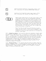
4072d/FEBh
D7
D5
dis-
RX/T
able
keys
D5
X
DJ
D4
dis-
V
Master
D1
DO
tran- di s- tran- dissit ion able sition able
able
V
D2
V
Stop
transitron
V
Step
S
tart
I
1
I
I
I
I
I
I
Trans itl on:
0=h igh to I oru
l=1 o\t/ to h iqh
Disable:
0 = enabfe
] = disable
RX/TX keys:
0 = enable use of
to enabfe external scan and
to disable external scan
I = disabl,e use of keys t.o contro]
RX key
TX key
externaL scan
0=
enabl-e use of external scan
1-- disable external scan and negJ.ect D6 -
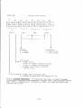
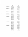
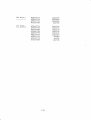
5.12.5
STANDIRD PR0GRAMMING
programm@
(ref.. Factory programming
255d/FFh are l-isted.
D0
The follouing lists apply to SKANTI standard
parameters f6r each type unless otheruise agreed
of Configuration
5-16
pR0M).
0nly data different
from
TRP
TRP
82505
82515
:
:
ADDR
DATA
4892d/FFCh
4AB5d/FF 6h
resd/c3h
zrod/Dzh
4072d/FEBh
16dl10h
4094d/FFEh
r65d/ A5h
195d/c3h
2r0d/Dzh
40e2d/rrch
4AB6d/Ff 6h
r6d/rsh
4072d/rEBh
TRP
82525
:
4O94d/FFEh
4086d/FF 6h
4OB5d/Ff 5h
4012d/FEBh
r65d/ A5h
zrod/Dzh
zrod/Dzh
16dl10h
TRP
825]5
:
4094d/FFEh
4092d/FFCh
4086d/rF 6h
407zd/FEBh
r65d/ A5h
re5d/c3h
zrod/Dzh
r6d/ roh
TRP
82545
:
4O94d/FFEh
4092d/FFCh
r65d/ A5h
r95d/c3h
TRP
TRP
82555:
82555
:
4089d/Fr9h
195d/c3h
4OBBd/FFBh
4086d/FF 6h
4084d/FF 4h
re5d/c3h
zIOd/Dzh
6d/o6h
408Jd/FF3h
4072d/FEBh
2d/02
16dl10h
4O94d/FFEh
4089d/FF9h
4086d/FF 6h
4OB5d/FF5h
4084d/FF 4h
r65d/
A5h
195d/C3h
zrod/Dzh
2IOd/D?h
40üd/rF3h
6d/o6h
2d/ozh
4072d/FEBh
r.5dl10h
4A94d/FFEh
4A92d/FFCh
4O9Id/FFBh
4090dlFFAh
4089d/FF9h
4088d/FF8h
4086d/FF 6h
4084d/FF 4
4083d/FF3h
4072d/FEBh
r65d/ A5h
resd/c3h
7e5d/c3h
re5d/c3h
resd/c3h
195d/c3h
2I0d/Dzh
6d/o6h
2d/ozh
r6d/roh
5-I7
TRP
82575:
4094d/FFEh
4086d/Fr 6h
4085d/FF5h
r65d/ ASh
zrod/DZh
zrod/Dzh
4072d/FtBh
TRP B25BS:
16dl10h
4094d/FFEh
4092d/FFCh
4O9Td/FFBh
4090d/FF Ah
4089d/FF9h
4086d/FF 6h
4084d/Fr 4h
r65d/ A5h
195d/c3h
195d/c3h
195d/c3h
40BJd/Frih
195d/clh
zrod/Dzh
6d/o6h
2d/ozh
4072d/FEBh
16dl10h
5-18
Ierminal
Designation
I
TX RIM
2
GND
3
RX
4
GND
Di
rect ion
0utput
REM
5
2182
6
GND
7
SCAN S/S
SEL
Siqnal level
'iis-üäö
Remarks
Remote
Control SeriaI
Data
Control Seriaf
Data
Input
RS-?32C
Remote
0utput
741S00
High ruhen 2IB2
f
nput
o/r2
GND
9
TELEX KEY
I
I
AUX KEY
I
I
t
I
I
nput
selected
Start,/Stop of scanning (user
u
programmable
B
is
o/12
u
Keyes Tx
vhen L0l,r/
o/12
u
Keyes Tx
in
)
TELEX mode
GND
f
nput
or
in USB, LSB,
RJE modes when L0lil
AM
GND
TTLIX IN
-15 to +10 dBm
500 ohms audio
tnput
-15 to 10 dBm
600 ohms audio input. 0pen
in USB, LSB, AM or R3E modes
uhen AUX KEY is LOI'J *
0utput
-10 to 10
600 ohms audio out.put.
Internally adjustable
Output
0to5tr/
Load impedance B
I
nput
in
TELEX mode x
input.
Open
GND
AUX IN
GND
LINE
OUT
dBm
GND
SPEAKER SPEAKER +
KTY INHIBIT
ohms
I
nput
o/12
V
Inhibit keying ruhen L0W
I
nput
o/12
V
Reserved for
GND
OPTIONAL IN
future
GND
*
An optional- Line Transformer Board
input/output.
x*
KEY INHIBIT input
function 284.
lffiIi"
is applicable only
avar]able prov j-ding balanced
urhen
Preset bit 4 = rr1rr, see second
501-TS1 AUXILIARy TERMINALS, C0NTR0L UNIT
Table 5. 2
5-19
use
J€
J(
Terminal
Designat ion
Di
MIC
I
rection
S
No-
I
2
GND
3
tARP I ECE
+12V
0utput
HANDSET KEY
I
Designat ion
Terminal
Supply
for MIC. Amplifier
in USB, LSB, AM
Keyes Tx
or RlI
Signal level
rect ron
0utput-
T0 10-150
2
3
500 ohms. ControL.led by
ruhen
L0l,r/
SOCKET:
Di
No.
I
dB
VOLUME
+12\J
o/r2 u
nput
HE
Terminal
Internally adjustable
+/-B
0 - 10 m!i/
0utput
5
Remarks
50mV-lV
nput
4
j-gnal l-evel
Remarks
mV,/
or stereo headphones ma
beused. Bohm-5kohm
Built-in speaker is disconnected ruhen jack is inserMono
ted
-LS
Y
Desiqnation
Di
I
MORSE KIY
I
2
GND
T:
rection Signal- level
Remarks
No^
nput
o/r2
u
in CW
or MCV,J urhen L0trJ
Keyes Tx
IXTIRNAL C0NNECTIONS, CONTROL UNrr
Table 5. l
5-20
Terminal
Designation
Di
rect ion
Remarks
Nn^
1
2
Supply fron IZ/24/32 U battery
P 8250
Input
+
or
Screen
GND
3
I
TS
Supply fron IZ/24/iZ U battery
P 8250
nput
1
or
SUPPLY TIRMINALS, TRANSCTIVER UNIT
Table 5.4
Terminal
Designat ion
Direct ion
Max. Current
+24V
0utpuL
Note
Nn-
I
2
TX
0utput
ON
250
mA
j
+24V
0utput
Note
4
TX KEYED
0utput
250
5
+24V
0utput
Note
6
2182
0utput
250
l
I
GND
9
+24\l
RX
TX
10
KTYED
MUTE
I
I
1
mA
I
mA
nput
0utput
Note
Remarks
+ 24 V avail-able
is
Open
collector.
Lou uhen TX on
+ 24 V available rLihen equlpment
is
0N
is
0N
0pen collector.
Lov uhen TX KEYED
+ 24 V available ruhen equipment
Open collector.
Loru uhen TX KEYED on 2IB2 kHz
O/I2 U. Rx is muted vhen connected to GND
+ 24 V avaifable
ruhen TX
ON
is
0N
GND
Note
620
l:
Max.
IS 2 AUXILIARY
total current 1000 mA
TERMINALS, TRANSCE]VER UNIT
Table 5.5
5-2r
when equipment
0N
CTtNTRAL I )1,//i
TRPNSCI IVE!.
Cr/- !:K 2
au :kt
Vl€UtD;PCM ,tl .l//
/
r,z7Y
/o-o\
(r a)3
\--l
o
ND
at:
TCSET
-4-
LtsKrtttta
+/zt/ -a
apNu,3if
t
/(tt/:
\^
'Jil
/3
Tt/tx
)
,Mt|
r' ' )t -,
tN
(t)
'- ,:!tl-I
o
t"/oR9t
caNi',lttraPs
saRrrN!,
pND
CFBTE
caBt
2"
t
TYpf
r.2.5,nro _
2
:
il
LaPPS SrFpP 50 * O.5rrtrt
apEL[
(itE t{olt
Br;- aa,,,t
2)
,illPL f .i.5rn5t
ia aF
C]PPIR SIRUP /00 ' a.5 /-.,
5 - P)LE (0NilECTOi< (D/N 4 /5?4)
*MULr/u/tR[ :BBLF May BE usfD
993 626 s2
orf
: .' n. jy ii J5t t ,,.
., ita oNrf lvtlp:.
tP -if /lNTtilt"/A IUNi,,
dl/-tllitg RE LliY L1,/tk L
:tD trtR LaPi',\S1'1/:',tC
^
cnÄElypr ,?52//,J öB
SaRttNttl aPBLi 6t[ ivort i)
't_
L
ktv
2-P)LE JQCK PLUG a 6.35
s(.RE[^l{D 14J! TtW/Rt a.i3Li
t;odxrqr
'1.'r
tf a.r/vuE///[Nf
P
3;5,) itl.' :JFI'L
NaTt .i
O/S XSZ8
dul ]NOHd]I]IOIOVU
I^IVUDVIO gNIUIA
UOI
NOIlVIIVlSNI
H
t
J
0
)
g
U
0/
5
I
L
?
*r'r;lijii,i.iiiii\ijirt
rd
G
t=r E€
u!
3o
=l rOI
crrr
-
4r r!
r!
e@
VI L.,
-l
ol
ol
ol
EI
zl
=l
-l
crl
el
FI
zl
ol
t-rl
u-l
ot
15l
=l
cl
zl
=l
ol
pl
<l
it<l
FI
6l
zl
-l
N
n
o
€
6
6
=
m
I
t:'
e,
lrj
@l
<l
LJI
JI
sl
xl
<l
sl
a
e
[n
(\
@
z
=
=
&
lrJ
IJ.J
IJ
a
z
&
F
Ll-
c)
15
z
e
=
z
cf
F
J
J
F
tn
z.
N
o
I
€
r6
6
TERHINAL
"TX"
"RX" 6[0SK2
640SK1
;f?
i44:
til::i
:i6
tift
:,iää
:E::t :r..:.+
ti:::!
iii:i:li:
:iiltl::!:::
iNi:
(t'l:
si
iiiffi
iiidin'iii#
liiitiiiii
iijit
993 630 42
iiii;i:
,&
lh!.i
yr:
ffir#!'ti
640TS1
IJJ
o
o
o
tr,I
zIIJ
IJJ
E
o
o
o
lo
6t
N
FI
f
@
a
tz
a
a
3
J
o.
o.
3
a
E
UJ,
o
=
o.
o
a
FI
a
o.
lr
o
o
z
g
=
z
9
F
JJ
F
a
z
6
E
E
q
o{
x
trj
g
$t
('
o
(?
@
(l)
=
o
o
6. TECHNICAL DISCRIPTION
6.1 CONTROL UNIT
The Control Unlt cont.ains a loudspeaker, truo printed circuit boards, Control
Board[Zö'ö-land Audio Processinq[_6-@and ä membrane keyboard. In addition an
opt.ional Squelch Board G64andäi-optional Line Transformer Boardtll*üil may be
inslalled. It furthermore contains connections for handset, headphones,
extension speaker, morse-key and telex-equipment. The Block Diagram of the
Controf Unit illustrates t.he functions of each circuit board ryhile the
Interconnection Diagram shovs the interconnections betueen the boards (see
chapter 9 for diagrams). The control unit is housed in a Noryl (ppO) cabinet
suitable for tabletop or bulkhead mounting. The front panel can be tilted for
convenient. operation when the unit is mounted verti-cal1y as welf as
horizontally.
6.2
TRANSCEIVER UNIT
The Rx/Tx Assembly o_Lll'" Transceiver Unit contains the Rx,/Ex Siqnal path lffii.
a synthesizer BoardL_6_llJand a Master Oscittat.or@] (orGTjl ,l@] l. Thesi--'
boards are ]ocated in the door of t.he unit. TheTabinet itsefilöontains a
Stuitched Mode Pover 5upp1y rvhich converts the battery voltage to a stabilized
48 V voltaqe supplying the Power Amplifier and the Voltage donverter BoardfE4l
. The Voltage Converter produces various supply voltages necessary in the
equipment and provides galvanic isol-ation from the battery. SuppJ-y voltaqes,
signal and control vol-tages are distributed vra the Interconnecträn Boarä
to external units and to the Transceiver Control BoardlZZlryhich performstrn
ilre
centraf cont.rol- of the Transceiver Unit. The exciter output siqnal from the
Rx/Tx Assembly is routed lo t.he pover Amplifier Board[ZZdlthe or]tput from
which is filtered by the harmonic filters on p.A. Fir6;I_6271(or@1 ,EIgl).
6.3
ANTTNNA TUNING UNIT
The ATU consists of a Tuning Netruork, a Measuring System and a Microprocessor
Part. During the tune sequence a 5 dB Attenuator ts sruitched in to keep the
l-oad of the Porver Amplifier at approx. 50 ohms. The MPU ryill set up the Tuning
Netruork to give the best obtainable Sl{R, on basis of the measuring system
The Tuning Netruork comprises Capacitor Bank I, Capacitor Bank II and an
Inductor Bank. hlith these it is possible to form either an L or a pi matching
netuork. The capacitor Banks and the Inductor Bank are built up by binary
related capacitors respectively binary related coils. The setting'of the
Capacitors and CoiIs is accomplished by relays.
6-r
6.4
AC POhJER SUPPLY UNIT
The P 8250 is a combined AC/DC Pouer grpp]v especially developed
for powering
TRP 8250 Series. The input po\uer for p'a2lb rs nc, and the
output
is an
unregulated 32 V DC voltage.
the
a battery is required as a reserve soutce of electrical energy to the
radiotelephone equipment, it can be connected via the p 8250 power-supply.
By
means of the suitch on the front_ panel it is possible to select
betveen
AC or
Battery operation.
Vr/here
6.5
ALC AND PROTECTION SYSTEM
6.5.1 Automatic Level Control (ALC) The Transceiver Unit. has advanced
mfcroprocessor controlled automatic level system, ruhich ensuresan
that the
optimum pouer is delrvered to the Antenna Tuning Unit.
is initiated either by pressing TUNI on the Control
front panel or by keylng the transmitter ä1t", a fiequency
change has
been carried otrt-, is terminated by a Cld pulse of full po\uer yiln a durat.ion
of
The Tune Sequence, which
UniL
70
ms.
The siqnal level at the output of the Transceiver Unit is measured
by means of
a voltaoe and cttrrent peak-detector placed at the output
p.A. Filter
of
the
Assembli@J,ßul.r-dil: iÄ""ä"tector vorL?99 (9.0 v at 25o r,r output porLrer)
is applied to the Transcerver Control Board-@, pLj_9 (ftlpfRX),'Änd'compared ruith the output voltage (8.62 V) ol tf,"
"Sf tpBINT RTGIST[R,, in IC4Z_
3'2. The error signar ALC is ied to the RX/[X signal
prr-rz
F"ü..fm:-l
-Lignal
driving a voltage controlled attenuator placed in the exciLer
path.
rinally the
ALC y:1!:g:_ls compared in IC42-5,6 ruith a ramp voltage generated
by the "ALCHOLD REGISitR" and the correspondrÄq DAC (rcrb:
tn" tro
voltages equals, the ramp is stopped and svitcÄ tcazr-ro,l1 iswÄ"Ä
cl-osed. The ALC
voltage is nou constant generated by the "ALCH0LD REGISiER" and thereby the
garn of the Transmitter Signal Path is independent of the modulating signal.
b/hen MEDIUM P0hlER is selected, the ALC voltage generated by the
"ALCHSLD
REGISTER'' is increased by o.92). In L0hl POI^JER ä r+ og attänuator
placed
the Poruer Amplifier Assembly@6lcontrolled by PAATT is activated and theonALC
voltage is equal to the Full Töru"er preset value.
6,5,2 Protection Circuits
6,'.5
'.2,.I. . Poruer Amplifier Protection The Pouer Amplifier protection can
rnto t\uo main groups, slr/R protection and thermal protection.
or-vr-ded
The
ShJR
protection contains a reff ected power and outpuL
be
detector
at the output of the power Amplifier AssembfyläEJ. The'output
the
detector (pnprnx) is connected to the Transcei.ver cäÄüäi a"".a-@-, of
itz-1"
and is 0R'ed together urj-th the FILPEAK voltage from the p.A. Filter Assembly
9n"rfäz?J. Nor, if the sh/R at the outptlt. of the pover Ampritier Assembty
placed
6-2
vo-l-taqe
lffilincreases during a transmission an error voltage is
generated at IC4Z- I
exceeding the voltage generated by t.he "ALCH0LD RtGISTtRn thereby increasing
the ALC voltage and reduclng the output po\uer within I ms to a permissible
level.
The output of the reflected po\uer and output voltage detector is al-so used to
make an independent. 1ocal protecLlon of the Pover Amplifier by activating the
14 dB attenuator if the detect.or voltage exceeds 10 V. This ensures fully
protection of the Pouer Amplifier if the ALC-loop should be faulty or
disconnected. To reset the attenuator it 1s necessary to turn off the
po\uer of the transceiver in a feu seconds.
The thermal
main
protection consists of tuo thermosvltches mounted on the heatsink
of the Pouer Ampllfier
Assembly and an average/peak pouer detector.
is acttvat.ed if the heatsink temperature exceeds 100 deq. C.
Thereby logi-cal signal fCt fua to the Transceiver Control Board @ , iti-Sgoes low and the output po\uer is reduced by 5 dB. This is carrled out by
changing the reference voftaqe from the "SETP0INT REGISTIR" to 4.16 V and
increasing the voltage from the "ALCHOLD RtGISTER" by 0.82 V relative to the
One thermosrvitch
Full
Poruer
preset vaf ue.
The other thermosuritch is activated if the temperature of the heatslnk exceeds
110 deg. C. In thls case the supply voltage to the preamplifier rs cut ofi.
The average po\uer and the peak pover are compared tn rC4I-3r2. If, in a Full
Pouer transmission, the average po\uer exceeds the peak po\l/er mi-nus 3 dB, the
logical signal at IC41-l- goes high. If this conditron has been present durlng
one minute, e.g. by transmltting Cl,r/ with continuous key-down or broadcast moäe
telex, the output po\yer ryill be reduced by J dB (Sf f pOlruf voltage 5.7I U ,
ALCH0LD voltage increased by 0.54 V relative to Full Pover pr"set value). The
pou/er uill recover to Full Porver l-evel- rvhen the transmitter has been muted
during tuo minutes.
To enable Ful1 PorLrer ARQ Telex Transmission the system accepts keyi-ng dutycycles less than 50 96 and modulation rates greater than I baud withoüt pover
reduction.
6.5.2,2
ATU Protection To protect the Antenna Tuning Unit against excess
current, TE-i;AtanceTf the antenna is shortcircuiteä ,
current
"iurage to the
detector is provided. The output of the detector IANTAVR "n
is conneited
Transceiver Control BoardGTl , Pl4-I4 and is 0R'ed toqether ruith the FILPEAK
vortage from the P.A. Filter Assembly@ßFAm@. Nor, if the averaqe
current exceeds 5 A durj-ng a transmission an error voltage is generated at
IC/12-I exceeding the voltage generated by the I'ALCHOLD REGISTER" thereby
increasing the ALC voltage and reducing the output power and thereby the
average current.
Il thu SIIJR at. the lnput of the Antenna Tuning Unit exceeds 1:J logical signal
Sl,lr/ROK goes hiqh and Power Display Annunciator on Control Unit front panel
starts flashing informing the operator that a belter antenna match might be
6-3
obtained by carrying out a ne\u Tune Sequence.
To prevent overheating
of the Antenna Tuning Unit a temperature
is
incorporated. If the internal temperatur" oi the Antennä trninq sensor
Unit exceeds
Bf d99. Cr logical- signal TCO goes lou and the output pouer is reduced by 5
dB. (srtporur volt.age 4.J6 u, ALcuoro voltage increased by 0.82 V relative to
Full Poruer preset value).
6'5.2,3 Reduced Poruer-Indication In case of 5 dB reduced po\rer condition due
Lothermator''ReducedPoU/er,,ontheContro1Unit
front panel is lit. The annuncj-ator "Reduced Pouer" ruill also turn on if the
average po\l/er, in a ful1 porter transmission, exceeds the peak po\rer mj-nus J dB
during one minute. In t.his condition the pouer is reduced by 3 dB.
6-4
1,
PREVENTIVE MAINTINANCE
to the modern design of the TRP 8250 preventive maintenance can be reduced
to a mrnimum provided the equipment is correctly install-ed. To ensure maximum
performance and minimum repair trouble \ue recommend you to folloru below stated
headlines for preventive maintenance.
Due
1.
The condition of t.he battery should be checked at frequent interval-s. The
battery must afuays be fuIly charged and shoufd be topped up frequently
tvith distilled uater (liquid should be 5 to l0 mm above the plates).
2.
Check the condition
3.
Keep antenna feed-through insul-ators cl_ean and dry.
of
at regular intervafs.
antenna
installation,
ground connectlon and cables
4. fnsure that no objects are obstructing the free airflov through the cooling
fins at the back of the Transceiver Unit and keep the units fiee of dust
accumul-ation to prevent overheating.
l.I
Realignment
of Master 0scillator
6121613l614
The MasLer Oscillator frequency should be checked at least once a year. The
Master Oscillator determines the exact transmit and receive frequencies of the
equipment. The oscillator tends to age very s1ow1y ruith time, typlcally with
the highest. drift rate t.he first year. The check should be performed by a
qualified technician ruith the necessary test equipment at his disposal.
1.
Measurlng Equipment:
1.1 Frequency Counter:
Frequency ranqe
Input
impedance
)= 100 MHz
= 50
ohm
Sensitivity at least > 0.2
Accuracy better than 1
1.2
V
Hz
Range 0-50 deg. Centigrade
Thermometer:
2, Preparations:
2.1 Sruitch on the
')
') Remove
po\uer
at least J0 minutes before
the front shielding cover of the RX/[X
adjustment
Assembly.
the front door of the Transcei-ver Unit and disconnect al-l sockets
from the shielding cover of the Master Oscillator. Remove the shi-elding
cover by unscreruing the 4 screus.
2.3 Open
7-r
2.4 Note if the
TCX0
is
marked
rvith a frequency offset.
2.5 Connect all sockets again.
2.5 Measure the temperature cfose to the Master Osciflator and take the
necessary arranqlements to keep it betueen 20 and 30 deg. Celsius. Be
sure that thermal equilibrium has taken place before aäjustment.
3.
Realignment
l.l
of Master Oscillator:
D:-sconnect the socket from pL2 on the RX/EX signal path[äö-lcarrying
Lhe injection signal to the lst. mixer. Connec[ the freffincy countör
to the socket.
3.2 Key-in
Unit.
USB mode
and a receiver frequency
of
26.68000 MHz on
the
ControL
3.3 Adjust. Rl unlil the counter reads f = JI.680000 MHz +/_ I Hz. If the
TCXO is marked rvith a frequency of,fset, multlply the offset by 7 and
add to the frequency stated above. For example:'
offset +2 Hz
Add7x2=14Hz
Adjust t-o f = 71.580014
Frequency
l{Hz
+/- I
Hz
3.4 Replace all covers and sockets again.
7.2
Replacement
of
backup battery
lithium backup battery should be changed ririthin four years after its
instaliation in the equipment. The expir"[ion date is marled on the battery.
The
If the time is exceeded the battery voltage may become too l-our vhich causes
the real--time clock to default t-o 00:00 anO the contents of the userprogrammab]e memory to get lost ryhen the equipment is switched OFF.
The battery is located in the Control
changed by a qualified technr_cian.
Unit on Controf Boardl@-|and should
1-2
be
B.
TROUBLI SHOOTING AND SERVICE
8.1 Malfunction
If the
equipment is not functioning correctly a check shou]d be made that is
being operated properly, see chaptär 4.
8.2
Replacement
of
FUSES
Unit contains tuo replaceable fuses focated at the front of
Supply. The fuses become accessible when the front
door is opened. Spare fuses are placed on the Sruitched Mode pouer SuppJ-y.
The Transceiver
the Suitched
Mode Pourer
The AC Pouer Supply Unit contains a fuse located
Spare fuses are Located behind the cover.
at the front of the unit.
ratings are given in table B.l beloru. Fuses ruith marked ratings ryithin 5
percent of the ratings must be used. Note that fast or sl-ory bl-oruin! fuses must
be used as specified.
Fuse
Locat ion
Fuse
Rating
4A
Transceiver
Unit
fast
Unit
IIO/I20
+48 V to
Equipment dead,
Vz
12.5 A slou
No RF
Mains input
No
but
output
light in DC OUTPUT
vith mains sruitch
position
Tab]e 8.I
B-1
Main
po\uer
LAMP
220/240 V:
5.1 A slory
blown
Relay operates when
Supply sruitch is activated. Voltage-indicator
lamp in Sruitched Mode
Pover Supply is lit when
po!/er is on.
48Vto
Pover Amplifier
Fast
AC Power
5upp1y
Symptom
Voltage Converter
15A
if fuse is
Funct ion
MAINS 0N
8.3
HOI'J TO MANUALLY TUNE THE ANTTNNA TUNING
FAILURE
IN
UNIT T0 2IB2 kHz IN
CASE
OF
THE AUTOMATIC TUNING SYSTEM''
1. Suitch SUPPLY OFF on Control Unit.
2.
Remove
cover from Antenna Tuning Unit
3. Locate AUro/ZrBz kHz toggle svitch
4. Refit the cover.
5.
The radiotelephone
8.4
is
nou ready
and srvitch
it to
zrBZ kHz (dounryards).
for operation on zrT2 k{z on]y.
DESCRIPTION OF STLF TEST FUNCTIONS
Self test can be done in truo different modes, auto mode and step mode. Auto
is intended for a quick verification of all functions, it ruill execute
all tests in sequence and stop if a malfunction rs detected. Step mode is
intended for service purposes, it allorys step by step testing and gives the
operator the possibility to make measurements during the tests and to repeat
tests. Thus it can be used as a buj-lt-in signal generator for many purposes.
The results of the tesLs are displayed on the RX dlsplay at the Control Unit.
ThÖ result consists of a test number, indicatlng ruhich test has been performed, and an error code indicating if the test rvas 0K. P]ease note that the
transmitter must be turned 0N before executinq the self test, otherurise the
synthesizer, exciter and transmitter t.ests ruill fail
mode
RX
The
0t)
02
I
-\
_t
I
ll
!5
test
error
number
code
error codes are to be interpreted as follows:
Error
00
display
code
Meaning
The test has passed.
A mal-function has been detected,
refer to specific
tesL description for precise information.
I
e1)
9B
Communicat.ion error
The test failed due t.o communication
and TU.
The test can not be executed due
CU
99
(special IF filters etc.
B-2
)
to
error
between
missing options
8.4.1
EXECUTION OF
SILF TEST IN
AUTO
MODE
trtrtrr
The
self test is
executed by pressing:
test wi-ll take severaf seconds, during which various sounds may be heard.
test uill stop urhen all tests have beän executed, or the first time an
error is detect.ed. hJhen the test stops, a test number and an error-code vill
be displayed. If the error-code is C0 no faults has been detected. If the
error-code is different. from 00, an error has been detected, refer to description of specific tests lor information on the fault and for appropriate actions. The t.est result ruil1 be displayed for 10 seconds, tfrerääfter the
Transceiver ryrll return to normal operation.
The
The
8.4.2
The
TXECUTION
self test is
OI SILF
TEST FROM AN ARBITRARY TEST NUMBIR (AUTO MCDE)
executed by pressing:
trtrtrtq
The test number is entered via the numeric keys into the receiver display.
Pressing "[NTER" rvill start self test from the specified test number if
possible. Pressing other keys than "fNTER" or numerics wil-f resume normaloperation as ruill pressing an j-nvalid test number. Execution of the self test
will progress as described in above passage.
8.4.3
The
TXICUTION OF SELF TTST
self test is
IN STEP MODE
executed by pressing:
trtrtrtq
test ruill start by executing test number I and displaying the test number
the error code. The test selup uill remain until tn"'opä""tor presses
"DIMMER UP"' then it rLrill proceed to the next test. The l-ast test ean be
repeated by pressing "DIMMER D0l,{N". If the operator presses any key but
"DIMMIR UP" or "DIMMER D0I^JN", the Transceiver ui]l return to noimal operatlon.
The Transceiver ruill return to normal- operation uhen the last test has been
The
and
executed.
B-J
Switched Mode Power Supply
SMPS incl. 622 and 623
RX/EX Signal Path 610
behind front cover of door
PCB 624 Transceiver
Control Board behind cover
PCB 627 or 628 or 629
P.A.Filters Board
PCB 620 lnterconnection Board
PCB 621 Voltage Converter
PCB 612 or 613 or 614 Master Oscillator