1
NewStep
TM
Actuator and Motion Controller
User’s Manual
2
Preface
EU Declaration of Conformity
We declare that the accompanying product, identified with the
mark,
complies with requirements of the Electromagnetic Compatibility Directive,
89/336/EEC and the Low Voltage Directive 73/23/EEC.
Model Number:
NewStep Actuator and Motion Controller Family (NSA12 and NSC100)
Year
mark affixed: 2003
Type of Equipment: Electrical equipment for measurement, control and
laboratory use
Standards Applied:
Compliance was demonstrated to the following standards to the extent
applicable:
BS EN61326-1: 1997+A1+A2 “Electrical equipment for measurement, control
and laboratory use – EMC requirements”
This equipment meets the CISPR 11 Class A Group 1 radiated and conducted
emission limits.
BS EN 61000-3-2:2001, Harmonic current emissions, Class A
BS EN 61000-3-3:2002, Voltage fluctuations and flicker
BS EN 61010-1:1993, A1+A2 “Safety requirements for electrical equipment for
measurement, control and laboratory use”
Alain Danielo
VP European Operations
Zone Industrielle
45340 Beaune-la-Rolande, France
Dan Dunahay
Director of Quality Systems
1791 Deere Avenue
Irvine, Ca. USA
Preface
Warranty
Newport Corporation warrants that this product will be free from defects in
material and workmanship and will comply with Newport’s published
specifications at the time of sale for a period of one year from date of shipment.
If found to be defective during the warranty period, the product will either be
repaired or replaced at Newport's option.
To exercise this warranty, write or call your local Newport office or
representative, or contact Newport headquarters in Irvine, California. You will be
given prompt assistance and return instructions. Send the product, freight
prepaid, to the indicated service facility. Repairs will be made and the instrument
returned freight prepaid. Repaired products are warranted for the remainder of
the original warranty period or 90 days, whichever first occurs.
Limitation of Warranty
The above warranties do not apply to products which have been repaired or
modified without Newport’s written approval, or products subjected to unusual
physical, thermal or electrical stress, improper installation, misuse, abuse,
accident or negligence in use, storage, transportation or handling. This warranty
also does not apply to fuses, batteries, or damage from battery leakage.
This warranty is in lieu of all other warranties, expressed or implied, including
any implied warranty of merchantability or fitness for a particular use. Newport
Corporation shall not be liable for any indirect, special, or consequential damages
resulting from the purchase or use of its products.
First printing 2003
© 2003 by Newport Corporation, Irvine, CA. All rights reserved. No part of this
manual may be reproduced or copied without the prior written approval of
Newport Corporation.
This manual has been provided for information only and product specifications
are subject to change without notice. Any change will be reflected in future
printings.
Newport Corporation
1791 Deere Avenue
Irvine, CA, 92606
USA
Part No 40745-01, Rev. A
3
4
Preface
Confidentiality & Proprietary Rights
Reservation of Title:
The Newport programs and all materials furnished or produced in connection
with them ("Related Materials") contain trade secrets of Newport and are for use
only in the manner expressly permitted. Newport claims and reserves all rights
and benefits afforded under law in the Programs provided by Newport
Corporation.
Newport shall retain full ownership of Intellectual Property Rights in and to all
development, process, align or assembly technologies developed and other
derivative work that may be developed by Newport. Customer shall not
challenge, or cause any third party to challenge the rights of Newport.
Preservation of Secrecy and Confidentiality and Restrictions to Access:
Customer shall protect the Newport Programs and Related Materials as trade
secrets of Newport, and shall devote its best efforts to ensure that all its personnel
protect the Newport Programs as trade secrets of Newport Corporation. Customer
shall not at any time disclose Newport's trade secrets to any other person, firm,
organization, or employee that does not need (consistent with Customer's right of
use hereunder) to obtain access to the Newport Programs and Related Materials.
These restrictions shall not apply to information (1) generally known to the
public or obtainable from public sources; (2) readily apparent from the keyboard
operations, visual display, or output reports of the Programs; 3) previously in the
possession of Customer or subsequently developed or acquired without reliance
on the Newport Programs; or (4) approved by Newport for release without
restriction.
Service Information
This section contains information regarding factory service for the source. The
user should not attempt any maintenance or service of the system or optional
equipment beyond the procedures outlined in this manual. Any problem that
cannot be resolved should be referred to Newport Corporation.
Preface
Technical Support Contacts
North America & Asia
Europe
Newport Corporation Service Dept.
Newport/MICRO-CONTROLE S.A.
1791 Deere Ave.
Zone Industrielle
Irvine, CA 92606
45340 Beaune la Rolande, FRANCE
Telephone: (949) 253-1694
Telephone: (33) 02 38 40 51 56
Telephone: (800) 222-6440 x31694
Newport Corporation Calling Procedure
If there are any defects in material or workmanship or a failure to meet
specifications, promptly notify Newport's Returns Department by calling 1-800222-6440 or by visiting our website at www.newport.com/returns within the
warranty period to obtain a Return Material Authorization Number (RMA#).
Return the product to Newport Corporation, freight prepaid, clearly marked with
the RMA# and we will either repair or replace it at our discretion. Newport is not
responsible for damage occurring in transit and is not obligated to accept
products returned without an RMA#. E-mail: [email protected]
When calling Newport Corporation, please provide the customer care
representative with the following information:
•
Your Contact Information
•
Serial number or original order number
•
Description of problem (i.e., hardware or software)
To help our Technical Support Representatives diagnose your problem, Please
note the following conditions:
•
Is the system used for manufacturing or research and development?
•
What was the state of the system right before the problem?
•
Have you seen this problem before? If so, how often?
•
Can the system continue to operate with this problem? Or is the system
non-operational?
•
Can you identify anything that was different before this problem occurred?
5
6
Preface
Table of Contents
EU Declaration of Conformity ............................................................................. 2
Warranty ........................................................................................................... 3
Confidentiality & Proprietary Rights ................................................................... 4
Technical Support Contacts.................................................................................. 5
List of Figures ...................................................................................................... 8
List of Tables........................................................................................................ 8
1
Safety Precautions
9
1.1
1.1.1
1.1.2
1.1.3
1.2
1.2.1
1.2.2
1.3
1.3.1
1.3.2
1.3.3
1.3.4
Definitions and Symbols.................................................................... 9
European Union CE Mark ................................................................. 9
CSA Mark.......................................................................................... 9
Direct Current (DC) ......................................................................... 10
Warnings and Cautions.................................................................... 10
General Warnings ............................................................................ 11
General Cautions ............................................................................. 11
Manual Conventions........................................................................ 11
Acronyms......................................................................................... 11
Keys, Buttons and Icons .................................................................. 12
User Input ........................................................................................ 12
The Display...................................................................................... 12
2
Features & Specifications
2.1
2.2
2.2.1
2.3
2.4
2.5
2.5.1
2.5.2
Product Overview ............................................................................ 13
Hardware Configuration .................................................................. 13
Communication Protocol ................................................................. 15
Connection to Non-Newport Controllers......................................... 15
Features Layout ............................................................................... 16
Outside Dimensions......................................................................... 16
Technical Specifications .................................................................. 17
Part Numbers ................................................................................... 19
3
Getting Started
13
21
Preface
3.1
3.2
3.3
3.4
3.5
3.6
Unpacking and Handling................................................................. 21
Inspection for Damage .................................................................... 21
Parts List.......................................................................................... 21
Choosing and Preparing Work Surface ........................................... 22
Electrical Requirements................................................................... 22
Operating Temperature.................................................................... 22
4
Operating NewStep
4.1
4.1.1
4.1.2
4.1.3
4.1.4
4.1.5
4.1.6
4.1.7
4.2
4.3
Overview ......................................................................................... 23
Operation Modes ............................................................................. 23
User Controls................................................................................... 24
Single Actuator, no Computer Interface (minimal configuration)... 25
Single Actuator with Computer Interface........................................ 26
Two Actuators, no Computer Interface ........................................... 27
Two Actuators with Computer Interface ......................................... 28
Multiple Actuators with Computer Interface................................... 29
Operation Modes ............................................................................. 30
User Controls................................................................................... 30
5
Software
5.1
5.2
5.3
5.4
Overview ......................................................................................... 33
Software Installation........................................................................ 33
RS-232 Communication Requirements ........................................... 33
Using NewStep-Util ........................................................................ 34
6
NewStep Controller ASCII Command Set
6.1
6.1.1
Command Summary........................................................................ 43
Summary Table ............................................................................... 43
7
Maintenance & Service
7.1
7.2
7.3
Enclosure Cleaning.......................................................................... 75
Technical Support............................................................................ 75
Service Form ................................................................................... 77
23
33
43
75
7
8
Preface
List of Figures
Figure 1
Figure 2
Figure 3
Figure 4
Figure 5
Figure 6
Figure 7
Figure 8
Figure 9
Figure 10
Figure 11
Figure 12
Figure 13
Figure 14
Figure 15
Figure 16
Figure 17
CE Symbol ..............................................................9
CSA mark................................................................9
Direct Current Symbol ..........................................10
Features Layout View ...........................................16
Outline Dimensions for NewStep Actuator. .........16
Outline Dimensions for NewStep Controller........17
NewStep-Util Software Icon.................................34
NewStep-Util Opening Screen..............................34
Initializing Controller screen ................................35
Initializing another Controller dialog box.............36
Scan Controllers screen.........................................36
Main screen...........................................................37
View all Tab Screen..............................................39
Move Tab Screen ..................................................40
Cycle Utility Screen ..............................................41
Status screen..........................................................41
Software and Hardware Information Screen.........42
List of Tables
Table 1
Table 2
Table 3
Table 4
Table 5
Table 6
Table 7
Table 8
NSA12 Actuator Specifications.............................................17
NSC100 Controller Specifications.........................................18
Environmental Specifications ................................................18
Part Numbers .........................................................................19
LED Status Table...................................................................24
LED Status Table...................................................................30
Summary Of Commands Table .............................................44
Technical Customer Support Contacts...................................75
1
Safety Precautions
1.1
Definitions and Symbols
The following terms and symbols are used in this documentation and also appear
on NewStep Actuator and Controller where safety-related issues occur.
1.1.1
European Union CE Mark
Figure 1
CE Symbol
The presence of the CE symbol in or on Newport Corporation equipment means
that it has been designed, tested and certified as essentially complying with all
applicable European Union (CE) regulations and recommendations.
1.1.2
CSA Mark
Figure 2
CSA mark
The presence of the CSA mark” indicates that it has been designed, tested and
certified as complying with all applicable U.S. and Canadian safety standards.
9
10
1.1.3
Safety Precautions
Direct Current (DC)
Figure 3
Direct Current Symbol
This symbol indicates on the rating plate that the NewStep Actuator and
Controller are suitable for direct current only.
1.2
Warnings and Cautions
The following are definitions of the Warnings, Cautions and Notes that are used
throughout this manual to call your attention to important information regarding
your safety, the safety and preservation of your equipment or an important tip.
WARNING
Situation has the potential to cause bodily harm or death.
CAUTION
Situation has the potential to cause damage to property or equipment.
NOTE
Additional information the user or operator should consider.
Safety Precautions
1.2.1
General Warnings
Observe these general warnings when operating or servicing this equipment:
•
Read all warnings on the unit and in the operating instructions.
•
Do not use this equipment in or near water.
•
Only connect the power cord to a grounded power outlet.
•
Route power cords and other cables so they are not likely to be damaged.
•
Disconnect power before cleaning the equipment. Do not use liquid or
aerosol cleaners; use only a damp lint-free cloth.
•
To avoid explosion, do not operate this equipment in an explosive
atmosphere.
1.2.2
General Cautions
Observe these cautions when operating or servicing this equipment:
•
Use only the specified replacement parts.
•
Follow precautions for static sensitive devices when handling this equipment.
•
This product should only be powered as described in this manual.
•
There are no user-serviceable parts inside the NewStep Unit.
•
If this equipment is used in a manner not specified within this manual, the
protection provided by the equipment may be impaired.
•
Do not position this equipment in a location that would make it difficult to
disconnect the AC power cord.
1.3
Manual Conventions
The following conventions and standards will be used in this manual.
1.3.1
Acronyms
A word formed from the initial letters of a name, for example: Read Only
Memory (ROM). In this manual acronyms will appear on the first occurrence
and whenever necessary for clarification, acronyms will be enclosed in
parentheses following their definition.
11
12
Safety Precautions
1.3.2
Keys, Buttons and Icons
Computer keyboard keys and onscreen buttons and icons are used in the text to
describe many user operations. The key-top symbol as it appears on the
keyboard, the button or icon name is represented in boldface type. For example:
Ctrl is used for the Control key.
1.3.3
User Input
Text that is required to be typed in, will be shown in the boldface type courier
(new) font as shown below:
DISKCOPY A: B:
1.3.4
The Display
Text generated by the computer that appears on its display is presented in the
typeface courier (new) font as shown below:
FORMAT complete
2
Features & Specifications
2.1
Product Overview
CAUTION
Please note that NextStep Actuator and Controller are high precision
instruments. Please use proper care when handling or storing the
instrument.
Newport’s NewStepTM micrometer replacement actuator and controller is an ideal
system for motorizing fine-positioning stages and mounts in opto-mechanical
systems. The NewStepTM family has been designed for hands-off adjustment of
hard-to-reach mirror mounts. Such applications include hands-off adjustment of
hard-to-reach mirror mounts or adjustments of optical mounts that are sensitive to
forces applied while twisting a knob. For example, optimizing the alignment of a
laser cavity or adjusting the pointing of a beam over a long distance.
2.2
Hardware Configuration
The serial (RS-485) communication interface on the NSC100 controller is
accessed through RS485 toRS232 converter. The pin out is designed so that you
can plug RS485 to RS232 converter directly into PC’s RS232 port.
See diagram next page.
13
14
Getting Started
NOTE
NSC100 is designed so that user can manually control NSA12 NewStep actuator by
adjusting velocity/enable knob or remotely using PC’s RS232 comport to control
NSA12 NewStep actuator.
Safety Precautions
2.2.1
Communication Protocol
The RS-232C interface must be properly configured on both devices
communicating. A correct setting is one that matches all parameters (baud rate,
number of data bits, number of stop bits, parity type and handshake type) for
both devices.
The NewStep controller RS-232C configuration is fixed at 19200 bps, 8 data
bits, no parity, and 1 stop bit.
To prevent buffer overflow when data is transferred to the NewStep controller
input buffer, a CTS/RTS hardware handshake protocol is implemented. The host
terminal can control transmission of characters from the controller by enabling
the Request To Send (RTS) signal once the controller’s Clear To Send (CTS)
signal is ready. Before sending any further characters, the controller will wait for
a CTS from the host.
As soon as its command buffer is full, the controller de-asserts CTS. Then, as
memory becomes available because the controller reads and executes commands
in its buffer, it re-asserts the CTS signal to the host terminal.
2.3
Connection to Non-Newport Controllers
CAUTION
Newport takes no responsibility for improper functioning or damage
of an actuator when it is used with any non-Newport controllers.
CAUTION
Newport guarantees the CE compliance of the NewStep actuators
only if they are used with Newport cables and controllers.
15
16
Getting Started
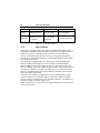
2.4
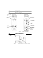
Features Layout
Velocity /Enable
Knob
Status LED
CSA Compliance
CE Compliance
Parameter
Reset
Product Label
Mounting
Screws
(optional)
Cable securing
tab mounting
location
(optional)
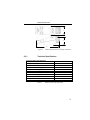
Figure 4
2.5
Features Layout View
Outside Dimensions
Cable
Lock Nut
Figure 5
Outline Dimensions for NewStep Actuator.
Safety Precautions
2”
2”
6”
Figure 6
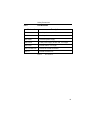
2.5.1
Outline Dimensions for NewStep Controller.
Technical Specifications
NSA12 Actuator Specifications
Size (mm)
Travel (mm)
Motor
Motion sensitivity (µm)
Repeatability (µm)
Bi-directional repeatability ((µm)
Max speed (mm/s)
Load capacity (N)
Limit switches
Remote control
Computer interface
Table 1
Ø30x65
11
Stepper Open loop
0.3
0.6
2.5
2 (load dependent)
18N minimum
Yes
Yes
Yes
NSA12 Actuator Specifications
17
18
Getting Started
NSC100 Controller Specifications
Output Power
Continuous current
0.4A @ 15VDC
Output Voltage
Maximum effective output voltage at continuous power
15V @ 0.4A
Input Power
Voltage
Average Current @ continuous output rating
Peak Current @ continuous output rating
Table 2
15V ±5%
0.6A
0.7A
NSC100 Controller Specifications
System Environmental Specifications
AC Input
100-240VAC, 1.5A
50/60Hz
±10%
Operating Temperature
5°C to 40°C
Operating Humidity
<85% relative humidity non-condensing
Storage Temperature
0-60°C
RH - <85% non-condensing
Altitude
<2000m (6562 feet)
Installation Category
II
Pollution Degree
2
Use Location
Indoor use only
Table 3
Environmental Specifications
Safety Precautions
2.5.2
Part Numbers
Part number
Description
NSA12
NewStep Actuator, 12 mm travel
NSC100
NewStep Motion controller
NSC-PS25
Universal power supply
NSC-PSC2
Cable power supply to NSC100, 3 m length
NSC-CB3
RS-485 Cable, 3 m length
NSC-CB-485-232
RS-232 to RS-485 Converter
NSC-JT
RS-485 Junction box
Table 4
Part Numbers
19
20
Getting Started
This page is intentionally left blank
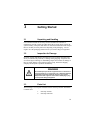
3
3.1
Getting Started
Unpacking and Handling
It is recommended that the NewStep Actuator and Motion Controller be
unpacked in your lab or work site rather than at the receiving dock. Unpack the
system carefully, small parts and cables are included with the instrument. Inspect
the box carefully for loose parts before disposing of the packaging. You are
urged to save the packaging material in case you need to ship your equipment.
3.2
Inspection for Damage
NewStep Actuator and Motion Controller have been carefully packaged at the
factory to minimize the possibility of damage during shipping. Inspect the box
for external signs of damage or mishandling. Inspect the contents for damage. If
there is visible damage to the instrument upon receipt, inform the shipping
company and Newport Corporation immediately.
WARNING
Do not attempt to operate this equipment if there is evidence of
shipping damage or you suspect the unit is damaged. Damaged
equipment may present additional hazards to you. Contact
Newport technical support for advice before attempting to plug
in and operate damaged equipment.
3.3
Parts List
The following is a list of parts included with the NewStep Actuator and Motion
Controller unit:
1. NewStep Actuator
2. NewStep Controller
21
22
Getting Started
3.
4.
Power cord/Power supply
User’s Manual
If you are missing any hardware or have questions about the hardware you have
received, please contact Newport.
3.4
Choosing and Preparing Work Surface
The NewStep Actuator and Motion Controller may be placed on any reasonably
firm table or bench during operation.
3.5
Electrical Requirements
NewStep Actuator and Motion Controller use low-noise linear AC-DC power
supplies to provide internal power. The power supply is auto-sensing for
voltages ranging between 100-240VAC, 1.5A at 50/60Hz.
Have a qualified electrician verify the wall socket that will be used is properly
polarized and properly grounded.
3.6
Operating Temperature
NewStep Actuator and Motion Controller are designed for operation in a
laboratory environment. Recommended ambient operating temperatures are
between 20 - 25°C. Operation at higher or lower ambient temperatures for
limited periods (e.g. several hours) will not cause any harm but may slightly
reduce the performance.
4
Operating NewStep
CAUTION
Before operating the NewStep Actuator and Motion Controller, please
adhere to cautions in Section1.
4.1
Overview
4.1.1
Operation Modes
The NewStep Controller has two major Modes of Operation, REMOTE and
LOCAL At power up, the Controller will default into REMOTE Mode. In
REMOTE Mode the controller will respond to Computer Communications only
and the Speed Adjustment Knob is disabled. In the LOCAL mode, the Speed
Adjustment Knob is enabled and the Computer Communications is disabled.
The Three colored LED (Yellow, Green, Red) on the body of the NewStep
Controller is used to indicate the mode of operation of the Controller. Different
colors in conjunction with blinking state represent different operating conditions
of the NewStep Controller. The LED Status Table summarizes the possible states
for the LED.
A Solid Yellow indicates that the Controller is in REMOTE mode and only
Computer Communications is active. A Solid Green is indicative of the
Controller being in LOCAL mode, where only the Speed Adjustment Knob is
active. A Solid Red is seen whenever a motion related error is detected. The
motion related errors are “Motor Not Connected” and “Hard or Soft Travel
Limit” detected errors. Also, a blinking Yellow is used when Firmware
Download is in progress.
23
24
Operating NewStep
LED
YELLOW
GREEN
RED
Solid
REMOTE Mode
LOCAL Mode
Error Condition
Blinking
REMOTE Mode,
In Motion
LOCAL Mode,
In Motion
Firmware Download
Table 5
4.1.2
LED Status Table
User Controls
In the LOCAL operations Mode, the controller responds to the Knob Velocity
Adjustment commands. Using the Knob the Actuator may be jogged in Forward
or Reverse directions. As the Knob position turns in one direction the jog
velocity will increase in that direction. There are seven jog speed settings for
either direction of the Knob. The Knob is spring loaded and the resting position
corresponds to zero speed.
Also, the Knob is equipped with a push button that is used for changing the
Operations Mode. By pressing this switch, the mode of operation changes
between REMOTE (power up default) and LOCAL mode. This switch is also
used for “Homing” the actuator. When this push button is pressed for longer than
5 seconds the Controller will initiate the Homing process, in which the actuator
will move toward the Hard limit (Negative direction) and home (Zero Position)
before the Negative Hard Limit.
On the back, the Parameter Reset Button is used for restoring factory default
Controller Address. The Controller Address is the number that the Computer
software will use to communicate with a particular Controller on the RS485 bus.
The factory default Controller Address is 0.
Below the Knob there are two side-by-side push buttons that are disabled for this
version of the product.
Operating NewStep
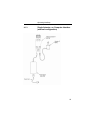
4.1.3
Single Actuator, no Computer Interface
(minimal configuration)
25
26
Operating NewStep
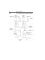
4.1.4
Single Actuator with Computer Interface
Operating NewStep
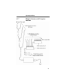
4.1.5
Two Actuators, no Computer Interface
27
28
Operating NewStep
4.1.6
Two Actuators with Computer Interface
Operating NewStep
4.1.7
Multiple Actuators with Computer
Interface
29
30
Operating NewStep
4.2
Operation Modes
The NewStep Controller has two major Modes of Operation, REMOTE and
LOCAL At power up, the Controller will default into REMOTE Mode. In
REMOTE Mode the controller will respond to Computer Communications only
and the Speed Adjustment Knob is disabled. In the LOCAL mode, the Speed
Adjustment Knob is enabled and the Computer Communications is disabled.
The Three colored LED (Yellow, Green, Red) on the body of the NewStep
Controller is used to indicate the mode of operation of the Controller. Different
colors in conjunction with blinking state represent different operating conditions
of the NewStep Controller. The LED Status Table summarizes the possible states
for the LED.
A Solid Yellow indicates that the Controller is in REMOTE mode and only
Computer Communications is active. A Solid Green is indicative of the
Controller being in LOCAL mode, where only the Speed Adjustment Knob is
active. A Solid Red is seen whenever a motion related error is detected. The
motion related errors are “Motor Not Connected” and “Hard or Soft Travel
Limit” detected errors. Also, a blinking Yellow is used when Firmware
Download is in progress.
LED
YELLOW
GREEN
RED
Solid
REMOTE Mode
LOCAL Mode
Error Condition
Blinking
REMOTE Mode,
In Motion
LOCAL Mode,
In Motion
Firmware Download
Table 6
4.3
LED Status Table
User Controls
In the LOCAL operations Mode, the controller responds to Speed Adjustment
Knob. Using the Knob the Actuator may be jogged in Forward or Reverse
directions. As the Knob position turns in one direction the jog velocity will
increase in that direction. There are seven jog speed settings for either direction
of the Knob. The Knob is spring loaded and the resting position corresponds to
zero speed.
Operating NewStep
Also, the Knob is equipped with a push button that is used for changing the
Operations Mode. By pressing this switch, the mode of operations changes
between REMOTE (power up default) and LOCAL mode. This switch is also
used for “Homing” the actuator. When this push button is pressed for longer than
5 seconds the Controller will initiate the Homing process, in which the actuator
will move toward the Hard limit (Negative direction) and home (Zero Position)
before the Negative Hard Limit.
On the back, the Parameter Reset Button is used for restoring factory default
Controller Address. The Controller Address is the number that the Computer
software will use to communicate with a particular Controller on the RS485 bus.
The factory default Controller Address is 0.
Below the Knob there are two side-by-side push buttons that are disabled for this
version of the product.
31
32
Operating NewStep
This page is intentionally left blank
5
Software
5.1
Overview
The Newport NewStep Utility Program provides access to a majority of NewStep
Controller’s functions and features, such as changing controller configuration,
monitoring status, and issuing move/jog commands.
5.2
Software Installation
The Newport NewStep Utility Program (NewStep-Util) is designed to run on any
commercially available Pentium™ class desktop personal computer. The
computer should have a minimum of 64MB of RAM. Newport recommends
using Windows 98™, Windows 2000 or NT.
To begin the installation process, put the CD in your CD driver and double-click
on Setup.exe. The installation will give you the option of where to load the files,
or you can use the default settings.
5.3
RS-232 Communication Requirements
For instrument communication, the instrument needs to be connected to the RS232 (COM Port) of the user’s PC via an RS232/RS485 converter. The cable
required is a DB9 Male/Female Pass-Thru cable.
The pin out is designed to interface directly with an IBM PC or compatible
computer, using a straight through cable.
The RS-232C configuration is fixed as follows:
Baud rate=19200bps; Data bits=8; Stop bits=1; Parity=NONE; Flow
control=xON / xOFF
33
34
Software
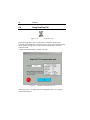
5.4
Using NewStep-Util
Figure 7 NewStep-Util Software Icon
NewStep-Util provides control of the features available in the NewStep
Controller. After installation is complete reboot your PC and execute NewStepUtil by double-clicking on the newly created icon in Newport / NewStep
Controller folder.
“Select Communication Port” window will open.
Figure 8
NewStep-Util Opening Screen
Choose Port Type – For RS232 choose the appropriate Port #, for example,
Com1 and Press Enter.
Software
After selecting the Port, if the Program finds any Uninitialized
Controllers(Controller address equal to zero), the “Initialize Controller” window
will open. The user then has to choose a valid controller address (a non-zero
value) that has not been assigned to other controllers.
NOTE
When initializing, only one Uninitialized Controller may be connected to the network
at a time. After specifying a Controller address and the Controller is initialized, other
Uninitialized Controllers may be connected, one at a time, and the “Initialize
Controller” Window will open again every time.
Figure 9 Initializing Controller screen
The program will ask if you want to initialize another Controller.
35
36
Software
.
Figure 10
Initializing another Controller dialog box.
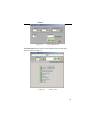
After all Controllers are initialized, “Scan Controller” window will open.
Select the range of controller numbers to scan for. The maximum range is from 1
to 255.
NOTE
Note that the time taken to scan the bus is proportional to the maximum scan
controller addresses selected.
Also, if the check box in the bottom is checked, the program will not scan the
RS485 network the next time the program is started
Position text
box
.
Figure 11
Scan Controllers screen
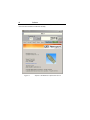
Software
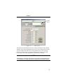
Now, the main screen will become available.
Position
text box
Figure 12
Main screen
The top portion of the main screen shows position information for the selected
controller. The position information can be shown in user defined units or microsteps by clicking on the button next to the position text box. Also, in the top
portion, the means to select a Controller (with up/down arrows) is provided.
Users can provide custom identification names for their controllers.
NOTE
Note that user can select one Controller at any given time to communicate to; also,
the “Stop Motion” and “Motor ON” buttons correspond to the selected Controller.
37
38
Software
The main window has five tabs to choose from: Move, View All, Setup Status,
and About.
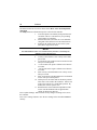
The Setup tab shows information specific to the selected controller.
1. Axis Description is an arbitrary description that user
can define. This is a convenient way for providing
custom names to controllers.
2. Measurement units (user units) are a user definable
string that will be shown next to the measurements.
3. Scaling is the scaling factor to convert the system
units (micro-steps) to user units.
NOTE
The data identified in items 1-3 is not stored in the controller. It is saved by the
software in a file on the user’s PC.
4.
Velocity is the actuator’s slew velocity in user units
per second.
5. Acceleration is the actuator travel acceleration in user
units per second squared.
6. + Travel Limit is the positive software travel limit in
user units.
7. - Travel Limit is the negative software travel limit in
user units.
8. Max Velocity is the Maximum travel velocity in user
units per second.
9. Max Acceleration is the Maximum travel acceleration
in user units per second squared.
10. Home preset is the offset used for the Home position.
This value is not stored in the controller. Instead, it is
used by the software as a virtual home position. By
default, this value is equal to zero.
11. Backlash Value is the backlash compensation value
in user units the backlash value is applied when
change of direction is detected.
Press “Update Settings” button in order for any changes in settings to be sent to
the controller.
Press “Save settings” button to save the new settings in the controller EEPROM
memory.
Software
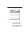
The next tab is the View All tab. In this screen all the active Controllers on the
RS485 network are shown.
Figure 13
View all Tab Screen
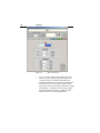
The Move tab enables the user to move the actuator. There are three ways to
move the actuator.
1. Jog – Jog is a mouse driven bar that moves the
actuator with a specific speed proportional to the
mouse location in both positive and negative
directions as long as the mouse is clicked.
2. Absolute Move – “Move to”, moves the actuator to
the user specified position.
3. Relative Move – “Increment”, moves the actuator by
the user specified position increment.
4. Home - clicking on this button will initiate “home
search” algorithm.
39
40
Software
Figure 14
5.
Move Tab Screen
Cycle – NewStep Cycle Utility window opens up
when the “Cycle” button is clicked. Here the user
can specify any two absolute positions between
which the actuator has to be moved. The dwell time
between moves can be specified in milli-seconds.
Clicking on “Start Cycle” button will initiate cycling
of the actuator. Clicking on “Stop Cycling” button
will stop the actuator cycling. Clicking on “Exit”
button will return to the main application.
Software
Figure 15
Cycle Utility Screen
The Status tab enables the user to review hardware status of LEDs, limit
switches, buttons, encoders, etc.
Figure 16
Status screen
41
42
Software
The About tab will show version of the Software Utility itself, and firmware
version for the instrument connected currently.
Figure 17
Software and Hardware Information Screen
6
NewStep Controller ASCII
Command Set
6.1
Command Summary
This document describes the supported two-letter ASCII commands that may be
used to configure and operate the NewStep Controller, when in REMOTE mode
(Yellow LED).
Since multiple NewStep Controllers may be placed on the RS485 Bus, each
controller will use a predetermined address (Controller Number) and by decoding
the address field of the incoming messages, it can determine if the message is
intended for it. If the incoming message does not have a matching address, the
controller will ignore the message. When a controller receives a command that
matches it’s address, depending on the message (query or set) it may or may not
respond back. If the Controller responds back, it will first send out the command
it received followed by the information it is to send.
For example, if a 234VE? Is sent to Controller Number 234, it will respond as
234VE? 1.0.
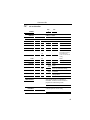
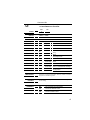
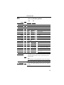
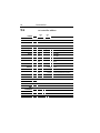
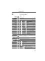
6.1.1
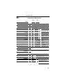
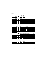
Summary Table
Cmd
Name
1.
2.
3.
4.
5.
6.
7.
8.
9.
10.
11.
AC
AU
BA
BZ
JA
MF
MO
OR
PA
PH
PR
Short Description
Acceleration
Maximum Acceleration
Backlash Compensation
Restore EEPROM
Jog
Motor OFF
Motor ON
Home
Absolute Position
Hardware Status
Relative Position
Command
Yes
Yes
Yes
Yes
Yes
Yes
Yes
Yes
Yes
No
Yes
Query
“?”
Yes
Yes
Yes
No
Yes
No
No
Yes
Yes
Yes
Yes
43
44
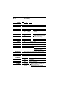
Command Set
12.
13.
14.
15.
16.
17.
18.
19.
20.
21.
22.
23.
RS
SA
SL
SM
SR
ST
TE
TP
TS
VA
VE
VU
Reset
Controller Number
Negative Software Limit
Save Memory
Positive Software Limit
Stop Motion
Tell Error
Tell Position
Controller Status
Velocity
Firmware version
Maximum Velocity
Table 7
Yes
Yes
Yes
Yes
Yes
Yes
No
No
No
Yes
No
Yes
Summary Of Commands Table
No
No
Yes
No
Yes
No
Yes
Yes
Yes
Yes
Yes
Yes
Command Set
AC
set acceleration
IMM
♦
USAGE
SYNTAX
MIP
xxACnn or xxAC?
PARAMETERS
Description
Range
Units
Defaults
xx
[ int ]
-
Controller number
nn
[float ]
-
Acceleration value
-
0 to 255
nn
-
0 to the maximum
programmed value in
AU command or
xxAC? to read current
setting
xx
-
None
nn
-
Full Steps/second2
xx
xx
nn
missing:
None
out of
range:
None
missing:
out of
range:
DESCRIPTION
RETURNS
Error 38, Parameter missing
Error 211, Maximum Acceleration
Exceeded
Error 230, Command not allowed
during motion
This command is used to set the acceleration
value for the actuator. It’s execution is
immediate. However, if there is motion in
progress the command is ignored.
If the “?” sign takes the place of nn value, this
command reports the current setting.
45
46
Command Set
REL.
COMMANDS
AU
set maximum acceleration and
deceleration
PA
execute an absolute motion
PR
execute a relative motion
VA
EXAMPLE
-
-
set velocity
21AC12.5
|
Set acceleration value to
12.5 for controller 21
21AC?
|
Read the acceleration value
from controller 21
Command Set
AU
set maximum acceleration
USAGE
SYNTAX
IMM
♦
MIP
xxAUnn or xxAU?
PARAMETERS
Description
Range
Units
Defaults
xx
[ int ]
-
Controller number
nn
[float ]
-
Acceleration value
xx
-
0 to 255
nn
-
0 to 500 or xxAU? to read current
setting
xx
-
None
nn
-
Full Steps/second2
xx
missing:
None
out of range:
None
nn
missing:
out of range:
Error 38, Parameter missing
Error 7, Parameter Out of Range
Error 230, Command not allowed
during motion
DESCRIPTION
This command is used to set the maximum acceleration value for the
actuator. It’s execution is immediate. However, if there is motion in
progress the command is ignored.
RETURNS
If the “?” sign takes the place of nn value, this command reports the
current setting.
REL.
COMMANDS
AC
-
set acceleration and deceleration
PA
execute an absolute motion
PR
execute a relative motion
47
48
Command Set
VA
EXAMPLE
-
set velocity
21AU12.5
|
21AU?
|
Set the maximum acceleration to 12.5 for
controller 21
Read the maximum acceleration value from
controller 21
Command Set
BA
set backlash compensation
USAGE
SYNTAX
IMM
♦
MIP
xxBAnn or xxBA?
PARAMETERS
Description
Range
Units
Defaults
xx
[ int ]
-
Controller number
nn
[ int ]
-
Backlash
compensation value
xx
-
0 to 255
nn
-
0 to 512
xx
-
None
nn
-
Micro-steps
xx
missing:
None
out of range:
None
nn
missing:
out of range:
DESCRIPTION
RETURNS
REL. COMMANDS
EXAMPLE
error 38, Parameter
missing
error 7, Parameter
out of range
This commands sets the backlash compensation
value.
If the “?” sign takes the place of nn value, this
command reports the current backlash setting value.
PA
-
execute an absolute motion
PR
-
execute a relative motion
25BA128
|
25BA?
|
Sets the backlash compensation
value to 128 for controller 25
Reads back the backlash
compensation value from
controller 25
49
50
BZ
Command Set
restore EEPROM content to default
USAGE
SYNTAX
IMM
♦
MIP
xxBZ
PARAMETERS
Description
xx
-
Controller number
Range
xx
-
None
Units
xx
-
None
Defaults
xx
DESCRIPTION
[ int ]
missing:
None
out of range:
None
This commands restores the default values for all the
nonvolatile settings.
RETURNS
REL. COMMANDS
EXAMPLE
25BZ
|
Restores the default settings
for controller 25
Command Set
JA
start jog motion
USAGE
SYNTAX
IMM
♦
MIP
♦
xxJAnn or xxJA?
PARAMETERS
Description
Range
Units
Defaults
xx
[ int ]
-
Controller number
nn
[ int ]
-
Jog setting
xx
-
0 to 255
nn
-
0 to ±8
xx
-
None
nn
-
None
xx
missing:
none
out of range:
none
nn
missing:
out of range:
DESCRIPTION
RETURNS
REL.
COMMANDS
EXAMPLE
error 38, Parameter missing
error 7, Parameter out of range
This command will start a jog motion with the specified speed setting
indicated by nn.
nn = 0 Jog velocity = 0 full-steps/sec
(0.00 mm/sec, for NSA25)
nn = ±1 Jog velocity = ±0.07 full-steps/sec (0.0005 mm/sec, for NSA25)
nn = ±2 Jog velocity = ±0.23 full-steps/sec (0.0015 mm/sec, for NSA25)
nn = ±3 Jog velocity = ±0.78 full-steps/sec (0.005 mm/sec, for NSA25)
nn= ±4 Jog velocity = ±3.12 full-steps/sec
(0.02 mm/sec, for NSA25)
nn = ±5 Jog velocity = ±15.62 full-steps/sec (0.1 mm/sec, for NSA25)
nn = ±6 Jog velocity = ±48.87 full-steps/sec (0.3 mm/sec, for NSA25)
nn = ±7 Jog velocity = ±156.62 full-steps/sec (1.0 mm/sec, for NSA25)
If the “?” sign takes the place of nn value, this command reports the last
speed setting value.
ST
-
Stop Motion
25JA-5
|
Start Jog motion with –50 fs/sec for controller 25
25JA?
|
Reads back the value of the last Jog speed from
controller 25
51
52
Command Set
MF
motor off
IMM
♦
USAGE
SYNTAX
MIP
♦
xxMF
PARAMETERS
Description
xx
[ int ]
-
Controller number
nn
[ int ]
-
On/off
Range
xx
-
0 to 255
Units
xx
-
None
Defaults
xx
missing:
None
out of range:
None
DESCRIPTION
RETURNS
REL.
COMMANDS
EXAMPLE
This command will turn the motor off.
This command has no return value.
ST
43MF
-
Stop Motion
|
Turn motor (actuator) off for Controller 43
Command Set
MO
motor on
USAGE
SYNTAX
IMM
♦
MIP
♦
xxMO
PARAMETERS
Description
xx
-
Controller number
Range
xx
-
0 to 255
Units
xx
-
None
Defaults
xx
missing:
None
out of range:
None
DESCRIPTION
RETURNS
REL.
COMMANDS
EXAMPLE
[ int ]
This command will turn the motor ON.
This command has no return value.
ST
43MO
-
Stop Motion
|
Turn motor (actuator)ON for Controller 43
53
54
Command Set
OR
search for home
USAGE
SYNTAX
IMM
♦
MIP
xxOR
PARAMETERS
Description
xx
-
Controller number
Range
xx
-
0 to 255
Units
xx
-
None
Defaults
xx
missing:
none
out of range:
none
DESCRIPTION
RETURNS
REL.
COMMANDS
EXAMPLE
[ int ]
This command will start the process of homing the actuator to its
negative hard limit. Once the actuator is homed, the position is set
to zero.
This command will return 1 if the actuator has been Homed and 0
if it has not been Homed since the last power up.
ST
-
Stop Motion
35OR
|
Home the actuator on Controller 35
35OR?
|
Return 1 or 0 if the actuator has been
Homed or not
Command Set
PA
move to absolute position
USAGE
SYNTAX
IMM
♦
MIP
xxPAnn or xxPA?
PARAMETERS
Description
Range
Units
Defaults
xx
[ int ]
-
Controller number
Nn
[ int ]
-
Position value
xx
-
0 to 255
nn
-
-60000 to 120000
Micro-steps
xx
nn
Missing:
None
out of range:
None
missing:
out of range:
Error 37, Parameter Missing
Error 7, Parameter Out of Range
Error 213, Motor Off
Error 230, Command not allowed
during motion
DESCRIPTION
This command initiates an absolute motion. When received, a
trapezoidal trajectory is generated with the predefined acceleration
and velocity and the actuator will move to the absolute position
specified by nn.
Note:
The command is not accepted while a motion is in progress.
RETURNS
If the “?” sign takes the place of nn value, this command reports the
last commanded position. Which is the same as the value read back
from TP? ± the predefined Backlash value, if there was a change of
direction.
55
56
Command Set
REL.
COMMANDS
EXAMPLE
AC
-
set acceleration
PR
-
move to relative position
ST
-
stop motion
VA
-
set velocity
12PA250
|
12PA?
|
Move Actuator on controller 12 to absolute
position 250
Read back the last commanded position
Command Set
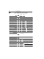
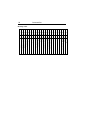
PH
get hardware status
USAGE
IMM
♦
SYNTAX
xxPH?
MIP
♦
PARAMETERS
Description
xx
-
Controller number
Range
xx
-
0 to 255
Units
xx
-
None
Defaults
xx
missing:
None
out of range:
None
DESCRIPTION
[ int ]
This command will return the value of the I/O ports of the
processor in the Controller. The are 3 bytes reported for 3 ports B,
D, and E represented in a decimal format.
NOTE: The retuned value are 3 bytes represented in decimal
format. Once converted to a binary representation the below Bit
Map table can be used determine the state of each I/O line.
RETURNS
REL.
COMMANDS
EXAMPLE
3 bytes for the values of the I/O ports.
none
14PH?
|
Returns the value of the I/O ports (3
bytes) of controller 14
57
Command Set
58
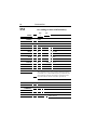
Bit Map Table
Bit Bit Bit Bit Bit Bit Bit Bit Bit Bit Bit Bit Bit Bit Bit Bit Bit Bit Bit Bit Bit Bit Bi Bit
23 22 21 20 19 18 17 16 15 14 13 12 11 10 9 8 7 6 5 4 3 2 1 0
I
I
I
I O I I I
I I I I I
I I
O O O
Green LED
Red LED
EEPROM Write Protect
N/A
N/A
N/A
N/A
N/A
Negative Travel Limit
Positive Travel Limit
Spare
Device Reset Button
Button A
Button B
Jog
Jog Knob Switch
Low Voltage Detect
Encoder A
Encoder B
Driver Fault line 1
Driver Enable 2
Driver Fault line 2
Debugger pin PGM
Debugger pin PGClcock
Debugger pin PGData
Command Set
PR
move by relative position
USAGE
SYNTAX
IMM
♦
MIP
xxPRnn or xxPR?
PARAMETERS
Description
Range
Units
Defaults
xx
[ int ]
-
Controller number
Nn
[ int ]
-
Position value
xx
-
0 to 255
nn
-
-60000 to 120000
Micro-steps
xx
nn
Missing:
None
out of range:
None
missing:
out of range:
Error 37, Parameter Missing
Error 7, Parameter Out of Range
Error 213, Motor Off
Error 230, Command not allowed
during motion
DESCRIPTION
This command initiates a relative motion. When received, a
trapezoidal trajectory is generated with the predefined acceleration
and velocity and the actuator will move to the relative position
specified by nn.
NOTE: The command is not accepted while a motion is in
progress.
RETURNS
If the “?” sign takes the place of nn value, this command reports
the last commanded position. Which is the same as the value read
back from TP? ± the predefined Backlash value, if there was a
change of direction.
59
60
Command Set
REL.
COMMANDS
EXAMPLE
AC
-
set acceleration
PR
-
move to relative position
ST
-
stop motion
VA
-
set velocity
12PR250
|
12PR?
|
Move Actuator on controller12by+250
micro-steps
Read back the last commanded position
Command Set
RS
reset the controller
USAGE
SYNTAX
IMM
♦
MIP
♦
xxRS
PARAMETERS
Description
xx
-
Controller Number
Range
xx
-
0 to 255
Units
xx
-
None
Defaults
xx
DESCRIPTION
RETURNS
[ int ]
missing:
none
out of range:
none
This command will reset the controller. This command will soft
reset the processor in the controller.
This command has no return value.
REL.
COMMANDS
none
EXAMPLE
31RS
|
Reset Controller31
61
62
Command Set
SA
set controller address
USAGE
IMM
♦
SYNTAX
xxSAnn
MIP
♦
PARAMETERS
Description
Range
Units
Defaults
xx
[ int ]
-
Controller number, current
nn
[ int ]
-
Controller number, new
xx
-
0 to 255
nn
-
0 to 255
xx
-
None
nn
-
None
xx
missing:
none
out of range:
none
nn
missing:
out of range:
DESCRIPTION
RETURNS
REL.
COMMANDS
EXAMPLE
error 38, Parameter missing
error 7, Parameter out of range
This command sets the Controller number.
This command has no return value.
none
0SA14
|
Sets the Controller number from 0 to 14
Command Set
SL
set left travel limit
USAGE
SYNTAX
IMM
♦
MIP
xxSLnn or xxSL?
PARAMETERS
Description
Range
Units
Defaults
xx
[ int ]
-
Controller Number
nn
[ int ]
-
Negative Software limit
xx
-
0 to 255
nn
-
-60000 to 1200000
xx
-
None
nn
-
Micro-steps
xx
Missing:
None
out of range:
None
nn
missing:
out of range:
Error 37, Parameter Missing
Error 7, Parameter Out of Range
Error 230, Command not allowed
during motion
DESCRIPTION
RETURNS
REL.
COMMANDS
This command will set the value of the negative software limits.
NOTE: The value of Negative software limit should be less than
the value of the Positive Software limit.
If the “?” sign takes the place of nn value, this command reports
the value of the Negative Software limit.
SR
Positive Software Limit
PA
Absolute Move
PR
Relative Move
JA
EXAMPLE
-
-
Jog
72SL-100
|
725SL?
|
Sets the value of Negative software limit
to –100 for controller 72
Reads back the value of the Negative
Software Limit from controller 72
63
64
Command Set
SM
save settings to non-volatile memory
USAGE
SYNTAX
IMM
♦
MIP
xxSM
PARAMETERS
Description
xx
-
Controller Number
Range
xx
-
0 to 255
Units
xx
-
None
Defaults
xx
missing:
none
out of range:
none
DESCRIPTION
RETURNS
REL.
COMMANDS
EXAMPLE
[ int ]
This command is used to save controller configuration settings
from RAM to non-volatile EEROM memory. It should be used
after modifying parameters and settings to assure that the new
data will not be lost when the controller is powered off.
This command has no return value.
none
61SM
|
save changes for controller 61 to nonvolatile memory
Command Set
SR
set right travel limit
USAGE
SYNTAX
IMM
♦
MIP
xxSRnn or xxSR?
PARAMETERS
Description
Range
Units
Defaults
xx
[ int ]
-
Controller number
nn
[ int ]
-
Positive software limit
xx
-
0 to 255
nn
-
-60000 to 1200000
xx
-
None
nn
-
Micro-steps
xx
Missing:
None
out of range:
None
nn
missing:
out of range:
DESCRIPTION
Error 37, Parameter Missing
Error 7, Parameter Out of
Range
Error 230, Command not
allowed during motion
This command will set the value of the negative software limits.
NOTE: The value of positive software limit should be larger
than the value of the Negative Software limit.
RETURNS
REL.
COMMANDS
If the “?” sign takes the place of nn value, this command reports
the value of the Positive Software limit.
SL
PA
-
Negative Software Limit
Absolute Move
65
66
Command Set
PR
JA
EXAMPLE
Relative Move
-
Jog
72SR-100
|
725SR?
|
Sets the value of Positive software limit
to –100 for controller 72
Reads back the value of the Positive
Software Limit from controller 72
Command Set
ST
stop motion
USAGE
SYNTAX
IMM
♦
MIP
♦
xxST
PARAMETERS
Description
xx
-
Controller number
Range
xx
-
0 to 255
Units
xx
-
None
Defaults
xx
missing:
none
out of range:
none
DESCRIPTION
RETURNS
REL.
COMMANDS
EXAMPLE
[ int ]
This command stops a motion in progress using deceleration rate
programmed with AC (set deceleration) command on the specified
controller.
This command has no return value.
MO
41ST
-
Motor ON/OFF
|
Stops the motion of the actuator on
controller 41
67
68
Command Set
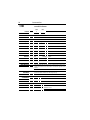
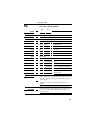
TE
read error code
USAGE
IMM
♦
SYNTAX
xxTE?
MIP
♦
PARAMETERS
Description
xx
-
Controller number
Range
xx
-
0 to 255
Units
xx
-
None
Defaults
xx
missing:
None
out of range:
None
DESCRIPTION
RETURNS
REL. COMMANDS
EXAMPLE
[ int ]
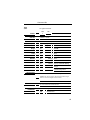
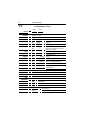
This command is used to read the error code.
Error Code as described in table below
none
23TE?
|
Returns Error code
Command Set
Error Code Table
Description
Error Code
No Errors
0
Driver Fault (Open Load)
1
Driver Fault (thermal shut down)
2
Driver Fault (Short)
3
Invalid Command
6
Parameter Out of Range
7
No Motor connected
8
Brown Out
10
Command Parameter Missing
38
Positive Hardware Limit Detected
24
Negative Hardware Limit Detected
25
Positive Software Limit Detected
26
Negative Software Limit Detected
27
Max Velocity Exceeded
210
Max Acceleration Exceeded
211
Motor Not Enabled
213
Switch to invalid axis
214
Homing Aborted
220
Parameter Change Not Allowed During Motion
226
69
70
Command Set
TP
read position
USAGE
IMM
♦
SYNTAX
xxTP?
MIP
♦
PARAMETERS
Description
xx
-
Controller number
Range
xx
-
0 to 255
Units
xx
-
None
Defaults
xx
missing:
None
out of range:
None
DESCRIPTION
[ int ]
This command returns the position of the actuator in micro-steps.
NOTE: The controller operates in an “open loop” fashion and it
returns the “theoretical” value of the position. Therefore, the actual
actuator position may be different from the read-back value.
RETURNS
REL.
COMMANDS
EXAMPLE
Position in micro-steps
PA
-
Absolute Position
PR
-
Relative Position
JA
-
Jog
25TP?
|
Returns the position value of the Actuator
on controller 25.
Command Set
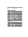
TS
controller status
USAGE
IMM
♦
SYNTAX
xxTS?
MIP
♦
PARAMETERS
Description
xx
-
Controller number
Range
xx
-
0 to 255
Units
xx
-
None
Defaults
xx
missing:
None
out of range:
None
DESCRIPTION
RETURNS
REL. COMMANDS
EXAMPLE
[ int ]
This command returns the controller status as following
Motor ON & Motion NOT In progress
81 Q
Motor ON & Motion In progress
80 P
Motor OFF & Motion NOT In progress
64 @
Position in micro-steps
MO
|
Motor ON
MF
|
Motor OFF
TP
|
Tell Position
TE
|
Tell Error
25TS?
|
Returns the controller status for
controller 25.
71
72
Command Set
VA
set velocity
USAGE
SYNTAX
IMM
♦
MIP
xxVAnn or xxVA?
PARAMETERS
Description
Range
Units
Defaults
xx
[ int ]
-
Controller number
nn
[ float ]
-
Velocity
xx
-
0 to 255
nn
-
0 to the maximum programmed
value in VU command or xxVA?
to read current setting
xx
-
None
nn
-
Full-steps/second
xx
missing:
none
out of range:
none
nn
missing:
out of range:
DESCRIPTION
RETURNS
REL.
COMMANDS
EXAMPLE
Error 37, Parameter Missing
Error 210, Max Velocity
exceeded
Error 230, Command not
allowed during motion
This command set the value of Velocity in full-step/second.
The value of Velocity in full-steps/second
VU
-
Maximum Velocity
AC
-
Acceleration
AU
-
Maximum Acceleration
17VA26.6
|
17VA?
|
Sets the Velocity for controller 17 to
26.6 full-steps/second
Reads back the value of Velocity
Command Set
VE
read controller firmware version
USAGE
IMM
♦
SYNTAX
xxVE?
MIP
♦
PARAMETERS
Description
xx
-
Controller number
Range
xx
-
0 to 255
Units
xx
-
None
Defaults
xx
missing:
none
out of range:
none
DESCRIPTION
RETURNS
REL. COMMANDS
EXAMPLE
[ int ]
This command returns the firmware version with a
“Major.Minor” format.
Firmware version
none
38VE?
|
Returns Firmware version of the
controller 38.
73
74
Command Set
VU
set maximum velocity
USAGE
SYNTAX
IMM
♦
MIP
xxVUnn or xxVU?
PARAMETERS
Description
Range
Units
Defaults
xx
[ int ]
-
Controller number
nn
[ float ]
-
Velocity
xx
-
0 to 255
nn
-
0 to the maximum programmed
value in VU command or xxVA? to
read current setting
xx
-
None
nn
-
Full-steps/second
xx
missing:
none
out of range:
none
nn
missing:
out of range:
Error 37, Parameter Missing
Error 7, Parameter Out of Range
Error 230, Command not allowed
during motion
DESCRIPTION
RETURNS
REL.
COMMANDS
EXAMPLE
This command set the value of MaximumVelocity in full-step/second.
The value of Maximum Velocity in full-steps/second
VA
-
Maximum Velocity
AC
-
Acceleration
AU
-
Maximum Acceleration
17VU200
|
17VA?
|
Sets the Velocity for controller 17 to 200 fullsteps/second
Reads back the value of Velocity
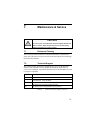
7
Maintenance & Service
CAUTION
There are no user serviceable parts inside the NewStep Actuator and
Motion Controller. Work performed by persons not authorized by
Newport Corporation will void the warranty.
7.1
Enclosure Cleaning
The NewStep Actuator and Motion Controller should only be cleaned with a
soapy water solution. Do not use an acetone or alcohol solution, this will damage
the finish of the enclosure.
7.2
Technical Support
This section contains information regarding factory service for the NewStep
Actuators and Controllers. The user should not attempt any maintenance or
service of the equipment. Any problem that cannot be resolved should be referred
to Newport Corporation.
Telephone
1-800-222-6440
Fax
1-949-253-1479
Address
Newport Corporation Service Department.
Email
[email protected]
Web Page
URL
http://www.newport.com/Support/Technical_Help/
http://www.newport.com/Support/Service_and_Returns/
1791 Deere Ave. Irvine, CA 92606
Table 8
[email protected]
Technical Customer Support Contacts
75
76
Maintenance and Service
Contact Newport to obtain information about factory service. Telephone
contacts number(s) are provided on a Service Form. Please have the following
information available:
•
Equipment model number (NSC100 NewStep Motion Controller or NSA12
Actuator)
•
Equipment Serial Number
•
Problem Description (document this by using the Service Form)
If the instrument is to be returned for repair, the user will be given a Return
Authorization Number that should be referenced in their shipping documentation.
Complete a copy of the Service Form as represented in sub-section 9.5 and
include it with your shipment
Maintenance and Service
7.3
Service Form
Newport Corporation
U.S.A. Office: 800-222-6440
FAX: 949/253-1479
Name ___________________Return Authorization _____________________
(Please obtain RA# prior to return of item)
Company ________________________________________________________
(Please obtain RA # prior to return of item)
Address ________________________________ Date ____________________
Country _______________________ Phone Number _____________________
P.O. Number ___________________ FAX Number ______________________
Item(s) Being Returned:
Model # _______________________ Serial # ___________________________
Description ______________________________________________________
Reason for return of goods (please list any specific problems):
77