1
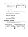
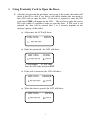
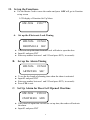
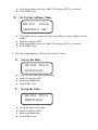
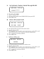
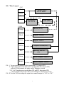
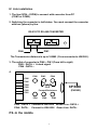
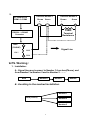
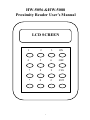
HW-5056 &HW-5088
Proximity Reader User’s Manual
LCD SCREEN
1
2
3
ON
4
5
6
OFF
7
8
9
CLS
*
0
#
ENT
1
★ Open door from the Keypad:
When the user press *, the reader
open the door and the screen
will show I-OPEN
The Screen Shows:
HW-5056
I-OPEN
9/01/12 00:03:23
★ To change the PIN code:
After the user presents the card and enters the PIN code, he/she has to
press OFF, and enter a new 4 digits PIN code.
The LCD will display as below after pressing OFF:
HW-5056 NEWCOD
K:****
★ When door is forced opened:
1. If the reader detects that the door is opened without legal procedures, it
will activate the alarm that has been functioned.
2. To relieve the alarm, simply present a valid card to reader.
When Alarm is activated
When the door is open through net work
HW-5056 ALARM
HW-5056
9/01/12 01:23:00
9/01/12
2
R-OPEN
00:03:23
I. Using Proximity Card to Open the Door:
1. After the user presents the proximity card or tag to the reader, the reader will
check if this ID is valid, if yes, then it will check whether this user need to
enter PIN code to open the door. If the user is required to enter the PIN
code, then CODE will appear on the LCD. The user has to enter the correct
PIN code within 10 seconds in order to open the door. If PIN code is not
required, the door will be opened after 1 to 4 seconds, depends on the
memory capacity of the reader.
♦ After senor, the LCD will show:
HW-5056
OPEN
I : ********
♦ Ender the password , the LCD will show:
HW-5056
CODE
I:******** K:****
I: Card number
K: PIN code
Enter the PIN code and press ENT
♦ If the code is incorrect, the LCD will show:
HW-5056
ERROR
I:******** K:****
♦ When the door is opened, the LCD will show:
HW-5056
OPEN
I:******** K:****
3
II. Set up the Functions:
♦ Use the Master Card to senor the reader and press OFF will get to Function
set up screen
LCD display of Function Set Up Menu
HW-5056
A.
FUN:**
Set up the Electronic Lock Timing
HW-5056
FUN:01
DROTM:01.0
SEC
♦ This is to set up the time electronic lock will take to open the door
♦ Input 01 and press ENT
♦ Enter any number between 1 and 255 and press ENT.( in seconds)
B.
Set up the Alarm Timing
HW-5056
ARTMT:020
♦
♦
♦
♦
FUN:02
SEC
To set the the length of alarming time when the alarm is activated.
Input 02 and press ENT
Enter any number between 1 and 255 and press ENT.( in seconds)
Press CLS to exit.
C. Set Up Alarm for Door Left Opened Overtime
HW-5056
OVRTM:020
FUN:03
MIN
♦ If the door left open time exceeds the set up time, the reader will activate
the alarm.
♦ Input 03 and press ENT
4
♦ Enter any number between 1 and 255 and press ENT.( in seconds)
♦ Press CLS to exit
D. Set Up Surveillance Time
HW-5056
FUN:04
SEETM:02.0
SEC
♦ This reader can be connected with a surveillance to meet a higher security
needs.
♦ Input 04 and press ENT
♦ Enter any number between 1 and 255 and press ENT.( in seconds)
♦ Press CLS to exit.
※ The above four functions will not be in active if enter 0.
E.
Set Up the Date
HW-5056 FUN:10
DATE:02/00/01
♦
♦
♦
♦
This is to set up the date in the reader
Input 10 and press ENT
Input year/month/date
Press CLS to exit.
F. Set up the Time
HW-5056 FUN:11
TIME:02/00/01
♦
♦
♦
♦
set up the time in the reader
Input 10 and press ENT
Input year/month/date
Press CLS to exit.
5
G. Set Up Reader Number Linked Through RS-485
HW-5056 FUN:14
LN485:******
♦
♦
♦
♦
H.
Set up the reader number
Input 14 and press ENT
Input the model number from 000000-999999, then press ENT
Press CLS to exit.
Delete All Learned Cards
HW-5056 FUN:60
22111000 WAIT
♦ The function delete all cards in the reader at once
♦ Input 60 and press ENT
♦ If the deletion is not successful or not enough memory, on the LCD, it will
show ERROR and leave the Function set up menu automatically.
♦ If it’s completed, it will show SETOK
♦ Press CLS to exit.
I.
To Delete All Records
HW-5056 FUN:61
SETOK
♦ This function delete all records in the reader at once
♦ Input 61 and press ENT
♦ If the deletion is not successful or not enough memory, on the LCD, it will
show ERROR and leave the Function set up menu automatically.
♦ If it’s completed, it will show SETOK
♦ Press CLS to exit.
6
III. Wire Layout
CN7
Red
+ Reader Power -DC 12V 600mA
Black
Blue
Green
+Lock Power –
DC12V 1A
Lock (NO)
CON8
Alarm (12V)
Orange
Black
Weigand DATA 0
White
Weigand DATA1
Yellow
Magnetic Switch (NC)
Open Door With SW
(NO)
Blue
Green
Link to Computer DATA --
Brown
Link to Computer DATA +
PS.. 1. To prevent the reader be taken apart,then JP3 connect PIN
2. If only Door Detection Function is needed,then JP2 connect PIN,
yellow(CON8)connect the other end of Magnetic Switch
3. If 1 & 2 functions are needed,then JP2 and JP3 disconnect PIN
yellow(CON8)connect the other end of Magnetic Induction Switch
PS.. JP1 on the PCB can adapt the open door connect output to “NO” or “NC”
7
IV. Link installation
1. The line (9PIN ~ 25PIN) is connect with converter from PC
(COM1 or COM2).
2. Switching the converter in half status. You must connect the converter
with box (phone) by line.
RS-232 TO RS-485 CONVERTER
PIN6
PIN1
The Transmissive distance is up to 1000M. ( From converter to HW-388 ).
3. The outlet of converter is PIN6 ~ PIN1 (From left to right)
PIN5 : DATA + Linked signal
PIN4 : DATA -4.
PIN6
PIN6
PIN5
PIN4
PIN3
PIN2
PIN1
PIN5
PIN4
150O
Forward Resistance
PIN1
PIN2
6P BOX
(PHONE)
PIN3
PIN5 : DATA + Connect to HW-5056 Brown Line : DATA +
PIN4 : DATA- Connect to HW-5056 Green Line: DATA-
PS..In the middle
8
5.
PC Output Port
COM1 or COM2
HW-5056 Number 1
Brown Green
+
-
HW-5056 Number 2
Brown
Green
+
-
150O
RS232ßà RS485
Converter
Terminal
Resistance
BOX
(PHONE)
150Ω
--
Signal Line
PIN5
PIN4
★ PS. Warning :
1. Installation :
A.. Signal line must connect to Number 1 from box(Phone), and
from Number1 to Number 2 and to Number 3… … …
BOX
Number1
Number
B.. Avoiding to the meshed installation.
Number 1
BOX (Phone)
Number 2
Number 3
9
Number
2. Box(Phone) have to install a forward
resistance (150 Ohm). The terminal resistance
has to install in the line of latest HW-5056.
èYou have to install two resistance ( 150 Ohm) in the whole line.
3. 4P or 6P is available only ( Line).
4. The output of PC port can changed by software.
5. The line must use insulating line. Please do not use the traditional
line to avoid the bad transmission.
10