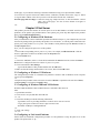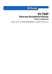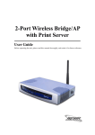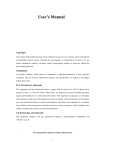
1
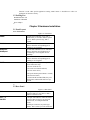
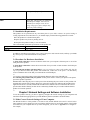
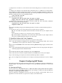
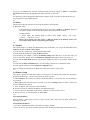
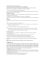
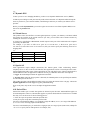
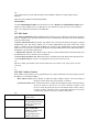
BIG-31/P - User’s Manual
Copyright
The contents of this publication may not be reproduced in any part or as a whole, stored, transcribed in an
information retrieval system, translated into any language, or transmitted in any form or by any means,
mechanical, magnetic, electronic, optical, photocopying, manual, or otherwise, without the prior written
permission.
Trademarks
All product, company, brand names are trademarks or registered trademarks of their respective companies.
They are used for identification purpose only. Specifications are subject to be changed without prior notice.
-1-
FCC Interference Statement
This equipment has been tested and found to comply with the limits for a Class B digital device pursuant to
Part 15 of the FCC Rules. These limits are designed to provide reasonable protection against radio
interference in a commercial environment. This equipment can generate, use and radiate radio frequency
energy and, if not installed and used in accordance with the instructions in this manual, may cause harmful
interference to radio communications. Operation of this equipment in a residential area is likely to cause
interference, in which case the user, at his own expense, will be required to take whatever measures are
necessary to correct the interference.
CE Declaration of Conformity
This equipment complies with the requirements relating to electromagnetic compatibility, EN 55022/A1
Class B, and EN 50082-1. This meets the essential protection requirements of the European Council
Directive 89/336/EEC on the approximation of the laws of the member states relation to electromagnetic
compatibility.
-2-
Table of Contents
Chapter 1 Introduction...............................................................................2
1.1 Functions and Features...................................................................2
1.2 Packing List....................................................................................3
Chapter 2 Hardware Installation................................................................4
2.1 Panel Layout...................................................................................4
2.2 Rear Panel.......................................................................................5
2.3 Installation Requirements...............................................................5
2.4 Procedure for Hardware Installation..............................................6
Chapter 3 Network Settings and Software Installation.............................8
3.1 Make Correct Network Settings of Your Computer.......................8
3.2 Install the Software into Your Computers......................................9
Chapter 4 Configuring NAT Router........................................................12
4.1 Start-up and Log in.......................................................................12
4.2 Status............................................................................................14
4.3 Toolbox.........................................................................................15
4.4 Primary Setup...............................................................................16
4.6 DHCP Server................................................................................19
4.7 Dynamic DNS..............................................................................20
4.8 Virtual Server................................................................................21
4.9 Special AP....................................................................................23
4.10 Packet Filter................................................................................24
4.13 Misc Items..................................................................................26
6.4.14 MAC Address Control.............................................................27
4.14 MAC Address Control................................................................28
Chapter 5 Print Server.............................................................................30
5.1 Configuring on Windows 95/98 Platforms...................................30
5.2 Configuring on Windows NT Platforms......................................32
5.3 Configuring on Windows 2000 and XP Platforms.......................33
5.4 Configuring on Unix based Platforms..........................................38
Appendix A TCP/IP Configuration for Windows 95/98.........................39
A.1 Install TCP/IP Protocol into Your PC..........................................39
A .2 Set TCP/IP Protocol for Working with NAT Router..................40
-1-
Chapter 1 Introduction
Congratulations on your purchase of this outstanding Broadband Router. This product is specifically
designed for Small Office and Home Office needs. It provides a complete SOHO solution for Internet
surfing and office resources sharing, and it is easy to configure and operate for even non-technical users.
Instructions for installing and configuring this product can be found in this manual. Before you install and
use this product, please read this manual carefully for fully exploiting the functions of this product.
1.1 Functions and Features
Broadband modem and IP sharing Connects multiple computers to a broadband (cable or DSL) modem
or an Ethernet router to surf the Internet.
Auto-sensing Ethernet Switch Equipped with auto-sensing Ethernet switch.
VPN supported Supports multiple PPTP sessions and allows you to setup VPN server and VPN clients.
Printer sharing (Optional) Embeds a print server to allow all of the networked computers to share one
printer.
Firewall All unwanted packets from outside intruders are blocked to protect your Intranet.
DHCP server supported All of the networked computers can retrieve TCP/IP settings automatically
from this product.
-2Web-based configuring Configurable through any networked computer’s web browser using Netscape or
Internet Explorer.
Packet filter supported
Packet Filter allows you to control access to a network by analyzing the incoming and outgoing
packets and letting them pass or halting them based on the IP address of the source and
destination.
Virtual Server supported Enables you to expose WWW, FTP and other services on your LAN
to be accessible to Internet users.
User-Definable Application Sensing Tunnel User can define the attributes to support the
special applications requiring multiple connections, like Internet gaming, video conferencing,
Internet telephony and so on, then this product can sense the application type and open multi-port
tunnel for it.
DMZ Host supported Lets a networked computer to be fully exposed to the Internet; this
function is used when special application sensing tunnel feature is insufficient to allow an
application to function correctly.
1.2 Packing List
Broadband router unit
Installation CD-ROM
Power adapter
-3-
Chapter 2 Hardware Installation
2.1 Panel Layout
2.1.1. Front Panel
Figure 2-1 Front Panel
System status indicators, Green. M1 is
flashed once per second to indicate system
is alive. When system is busy, M2 is
lighted.
Link status indicators, Green. The LED
flickers when the corresponding port is
sending or receiving data
10/100 status indicators, Green. The LED
flickers when the corresponding port is
transmitting or receiving data in 10 or
100Mbps.
Link status indicators, Green. The LED
flickers when the corresponding port is
sending or receiving data
To reset system settings to factory defaults,
please follow the steps:
1. Power off the device,
2. Press the reset button and hold,
3. Power on the device,
4. Keep the button pressed about 5 seconds,
5. Release the button,
6. Watch the M1 and M2 LEDs, they will
flash 8 times and then M1 flash once per
second.
M1&M2
WAN/Link
LAN/Speed
WAN/Speed
LAN/Link
RESET
WAN
Port 1 - 4
PRINTER
-4-
2.2 Rear Panel
Figure 2-2 Rear Panel
WAN port socket (RJ-45). This is where
you will connect to your cable (or DSL)
modem or Ethernet router.
LAN port socket (RJ-45). These are where
you will connect to device on your local
area network, for example HUB and
switch.
Parallel port connector (25-pins D-type
female). This is where you will connect the
shared printer. (Optional)
Power
Power inlet. This is where you connect the
included power adapter. Note that, the
included power adapter is DC 5V/2A.
Using wrong type of power adapter may
cause this product damage.
2.3 Installation Requirements
This product can be positioned at any convenient place in your office or house. No special wiring or
cooling requirements is needed. However, you should comply with the following guidelines to install:
Place this product on a flat horizontal plane.
Keep this product away from any heating devices.
Do not place this product in dusty or wet environment.
The recommended operational specifications of this product are:
Temperature
0 oC ~ 55 oC
Humidity
5 % ~ 90 %
In addition, remember to turn off the power, remove the power cord from the outlet, and keep your hands
dry when you try to install the hardware of this product.
-5-
2.4 Procedure for Hardware Installation
1. Setup LAN connection: connect an Ethernet cable from your computer’s Ethernet port to one of the
LAN ports of this product.
2. Setup WAN connection: connect the network cable from your cable or DSL modem to the WAN port
of this product.
3. Connecting this product with other hubs: In case you need not to connect with another hub, skip this
step. If you want to connect this product with another hub, connect one of the ports 1-7 to that hub by
crossover Ethernet cable. If the hub you connected has an UPLINK port,
-6you can also connect this product with straight through Ethernet cable to that UPLINK port.
4. Connecting this product with your printer: use the printer cable to connect your printer to the printer
port of this product. (Optional)
5. Power on: Connecting the power cord to power inlet and turning the power switch on, this product will
automatically enter the self-test phase. When it is in the self-test phase, the indicators M1 and M2 will be
lighted ON for about 5 seconds, and then M1 and M2 will be flashed 3 times to indicate that the self-test
operation has finished. Finally, the M1 will be continuously flashed once per second to indicate that this
product is in normal operation.
-7-
Chapter 3 Network Settings and Software Installation
To use this product correctly, you have to properly configure the network settings of your computers and
install the attached setup program into your MS Windows platform (Windows 95/98/NT/2000).
3.1 Make Correct Network Settings of Your Computer
The default IP address of this product is 192.168.123.254, and the default subnet mask is 255.255.255.0.
These addresses can be changed on your need, but the default values are used in this manual. If the TCP/IP
environment of your computer has not yet been configured, you can refer to Appendix A to configure it.
For example,
1. configure IP as 192.168.123.1, subnet mask as 255.255.255.0 and gateway as 192.168.123.254, or more
easier,
2. configure your computers to load TCP/IP setting automatically, that is, via DHCP server of this product.
After installing the TCP/IP communication protocol, you can use the ping command to check if your
computer has successfully connected to this product. The following example shows the ping procedure for
Windows 95 platforms. First, execute the ping command
ping 192.168.123.254
If the following messages appear:
Pinging 192.168.123.254 with 32 bytes of data:
Reply from 192.168.123.254: bytes=32 time=2ms TTL=64
a communication link between your computer and this product has been successfully established.
Otherwise, if you get the following messages,
Pinging 192.168.123.254 with 32 bytes of data:
Request timed out.
-8there must be something wrong in your installation procedure. You have to check the following items in
sequence:
1. Is the Ethernet cable correctly connected between this product and your computer?
Tip: The LAN LED of this product and the link LED of network card on your computer must be
lighted.
2. Is the TCP/IP environment of your computers properly configured?
Tip: If the IP address of this product is 192.168.123.254, the IP address of your computer must be
192.168.123.X and default gateway must be 192.168.123.254.
3.2 Install the Software into Your Computers
Skip this section if you do not want to use the print server function of this product.
Step 1: Insert the installation CD-ROM into the CD-ROM drive. The following window will be shown
automatically. If it isn’t, please run “install.exe” on the CD-ROM.
-9Step 2: Click on the INSTALL button. Wait until the following Welcome dialog to appear, and click on the
Next button.
Step 3: Select the destination folder and click on the Next button. Then, the setup program will begin to
install the programs into the destination folder.
-10Step 4: When the following window is displayed, click on the Finish button.
Step 5: Select the item to restart the computer and then click the OK button to reboot your computer.
Step 6: After rebooting your computer, the software installation procedure is finished.
Now, you can configure the NAT Router (refer to Chapter 4) and setup the Print Server (refer to Chapter
5).
-11-
Chapter 4 Configuring NAT Router
This product provides Web based configuration scheme, that is, configuring by Netscape Communicator or
Internet Explorer. This approach can be adopted in any MS Windows, Macintosh or UNIX based
platforms.
4.1 Start-up and Log in
Activate your browser, and disable the proxy or add the IP address of this product into the exceptions.
Then, type this product’s IP address in the Location (for Netscape) or Address (for IE) field and press
ENTER. For example: http://192.168.123.254.
After the connection is established, you will see the web user interface of this product. There are two
appearances of web user interface: for general users and for system administrator.
To log in as an administrator, enter the system password (the factory setting is ”admin”) in the System
Password field and click on the Log in button. If the password is correct, the
-12web appearance will be changed into administrator configure mode. As listed in its main menu, there are
several options for system administration.
-13-
4.2 Status
This option provides the function for observing this product’s working status:
A. WAN Port Status.
If the WAN port is assigned a dynamic IP, there may appear a “Renew” or “Release” button on
the Sidenote column. You can click this button to renew or release IP manually.
B. Modem Status.
C. Printer Status. The possible kinds of printer status include “Ready,” “Not ready,”
“Printing…”, and “Device error.”
When a job is printing, there may appear a “Kill Job” button on the Sidenote column. You
can click this button to kill current printing job manually.
-14-
4.3 Toolbox
This option enables you change the administrator password. Besides, you can get the information about
Firmware version and WAN's MAC Address.
You can view the system logs by clicking the View Log button.
You can reboot this product by clicking the Reboot button.
You can backup your settings by clicking the Backup Setting button and save it as a bin file. Once you
want to restore these settings, please click Firmware Upgrade button and use the bin file you saved.
You can click the Clone MAC button to copy the MAC address of your PC to be the MAC address of this
device.
You can click the Reset to Default button to reset the settings of this device to the default values.
You can upgrade firmware by clicking Firmware Upgrade button.
Note: we strongly recommend you to change the system password for security reason.
-15-
4.4 Primary Setup
This option is primary to enable this product to work properly. The setting items and the web appearance
depend on the WAN type. Choose correct WAN type before you start.
1. LAN IP Address: this product’s IP address. The default address is 192.168.123.254. You can change it
on your need.
2. WAN Type: WAN connection type of your ISP. You can click Change button to choose a correct one
from the following four options:
A. Static IP Address: ISP assigns you a static IP address.
B. Dynamic IP Address: Obtain an IP address from ISP automatically.
C. PPP over Ethernet: Some ISPs require the use of PPPoE to connect to their services.
D. Dial-up Network: To surf the Internet via PSTN/ISDN.
-164.4.1 Static IP Address
WAN IP Address, Subnet Mask, Gateway, Primary and Secondary DNS: enter the proper setting value
provided by your ISP.
4.4.2 Dynamic IP Address
1. Host Name: optional. Required by some ISPs, for example, @Home.
2. Renew IP Forever: this feature enable this product renew IP address automatically when the lease time is
being expired even the system is in idle state.
4.4.3 Dynamic IP Address with Road Runner Session Management.
LAN IP Address is the IP address of this product. It must be the default gateway of your computers.
WAN Type is Dynamic IP Address. If the WAN type is not correct, change it!
1. Host Name: optional. Required by some ISPs, e.g. @Home.
2. Renew IP Forever: this feature enable this product renew IP address automatically when the lease time is
being expired even the system is in idle state.
4.4.4 PPP over Ethernet
1. PPPoE Account and Password: the account and password your ISP assigned to you. If you don't want to
change the password, keep it empty.
2. PPPoE Service Name: optional. Input the service name if your ISP requires it.
3. Maximum Idle Time: the time of no activity to disconnect your PPPoE session. Set it to 0 will disable this
feature.
4.4.5 PPTP
1. My IP Address and My Subnet Mask: the private IP address and subnet mask your ISP assigned to you.
-172. Server IP Address: the IP address of the PPTP server.
3. PPTP Account and Password: the account and password your ISP assigned to you. If you don't want to
change the password, keep it empty.
4. Connection ID: optional. Input the connection ID if your ISP requires it.
5. Maximum Idle Time: the time of no activity to disconnect your PPTP session. Set it to zero or enable
Auto-reconnect to disable this feature. If Auto-reconnect is enabled, this product will automatically
connect to ISP after system is restarted or connection is dropped.
4.4.6 Dial-up Network
1. Dial-up Telephone, Account and Password: assigned by your ISP. If you don't want to change the
password, keep it empty.
2. Primary and Secondary DNS: automatically assigned if they are configured as "0.0.0.0."
3. Maximum Idle Time: the time of no activity to disconnect your dial-up session.
4. Baud Rate: the communication speed between this product and your MODEM or ISDN TA.
5. Extra Setting: needed to optimize the communication quality between the ISP and your MODEM or
ISDN TA
NOTE: Only specific models of routers with “COM port” will have “Dial up” function.
-18-
4.6 DHCP Server
The settings of TCP/IP environment include Host IP, Subnet Mask, Gateway, and DNS configurations. It is
not a simple task to correctly configure all the computers in your LAN environment. Fortunately, DHCP
provides a rather simple approach to handle all these settings. This product supports the function of DHCP
server. If you enable this product’s DHCP server and configure your computers as “automatic IP
allocation” mode, then when your computer is powered on, it will automatically load the proper TCP/IP
settings from this product. The settings of DHCP server include the following items:
1. DHCP Server: Choose “Disable” or “Enable.”
2. Range of IP Address Pool: Whenever there is a request, the DHCP server will automatically allocate an
unused IP address from the IP address pool to the requesting computer. You must specify the starting and
ending address of the IP address pool.
3. Domain Name: Optional, this information will be passed to the client.
To View the DHCP clients, you can click the Clients List button.
-19-
4.7 Dynamic DNS
To host your server on a changing IP address, you have to use dynamic domain name service (DDNS).
So that anyone wishing to reach your host only needs to know the name of it. Dynamic DNS will map the
name of your host to your current IP address, which changes each time you connect your Internet service
provider.
Before you enable Dynamic DNS, you need to register an account on one of these Dynamic DNS servers
that we list in provider field.
-20-
4.8 Virtual Server
This product’s NAT firewall filters out unrecognized packets to protect your Intranet, so all hosts behind
this product are invisible to the outside world. If you wish, you can make some of them accessible by
enabling the Virtual Server Mapping.
A virtual server is defined as a Service Port, and all requests to this port will be redirected to the computer
specified by the Server IP.
For example, if you have an FTP server (port 21) at 192.168.123.1, a Web server (port 80) at
192.168.123.2, and a VPN server at 192.168.123.6, then you need to specify the following virtual server
mapping table:
-21Service Port
Server IP
Enable
21
192.168.123.1 V
80
192.168.123.2 V
1723
192.168.123.6
V
-22-
4.9 Special AP
Some applications require multiple connections, like Internet games, Video conferencing, Internet
telephony and so on. Due to the firewall function, these applications can not work with pure NAT router.
Special Applications makes some of these applications to work with NAT router. If Special Applications is
still insufficient to allow an application to function correctly, try DMZ host in the Misc Items options.
1. Trigger: the outbound port number the application issued first.
2. Incoming Ports: when the trigger packet is detected, the inbound packets to the specified port numbers
are allowed to pass the firewall.
This product provides some predefined settings in the gray pad on the bottom of the web page. Choose the
Popular application and click Copy to copy the predefined setting.
Note! At any time, only one PC can use each Special Application tunnel.
-23-
4.10 Packet Filter
Packet Filter enables you to control what packets are allowed to pass the router. Outbound filter applies on
all outbound packets. However, Inbound filter applies on packets that destined to Virtual Servers or DMZ
host only. You can select one of the two filtering policies:
1. Allow all to pass except those match the specified rules
2. Deny all to pass except those match the specified rules
For source or destination IP address, you can define a single IP address (4.3.2.1) or a range of IP addresses
(4.3.2.1-4.3.2.254). An empty implies all IP addresses.
For source or destination port, you can define a single port (80) or a range of ports (1000-1999). Add prefix
"T" or "U" to specify TCP or UDP protocol. For example, T80,
-24U53, U2000-2999. No prefix indicates both TCP and UDP are defined. An empty implies all port
addresses.
Each rule can be enabled or disabled individually.
Inbound Filter:
To enable Inbound Packet Filter click the check box next to Enable in the Inbound Packet Filter field.
Suppose you have SMTP Server (25), POP Server (110), Web Server (80), FTP Server (21), and News
Server (119) defined in Virtual Server or DMZ Host.
-25-
4.13 Misc Items
1. IP Address of DMZ Host: DMZ (DeMilitarized Zone) Host is a host without the protection of firewall. It
allows a computer to be exposed to unrestricted 2-way communication. Note that, this feature should be
used only when needed.
2. Remote Administrator Host: In general, only Intranet user can browse the built-in web pages to perform
administration task. This feature enables you to perform administration task from remote host. If this
feature is enabled, only the specified IP address can perform remote administration. If the specified IP
address is 0.0.0.0, any host can connect to this product to perform administration task. When this feature is
enabled, the web port will be shifted to 88.
3. Administrator Time-out: The amount of time of inactivity before the Barricade will automatically close
the Administrator session. Set this to zero to disable it.
4. Discard PING from WAN side: When this feature is enabled, hosts on the WAN cannot ping the device.
5. Non-standard FTP port: You have to configure this item if you want to access an
-26FTP server whose port number is not 21(when Client uses active mode ). This setting will be lost after
rebooting.
6.
-27-
4.14 MAC Address Control
MAC Address Control allows you to assign different access right for different users and to assign a specific
IP address to a certain MAC address.
MAC Address Control Check “Enable” to enable the “MAC Address Control”. All of the settings in
this page will take effect only when “Enable” is checked.
Connection control Check "Connection control" to enable the controlling of which wired and wireless
clients can connect to this device. If a client is denied to connect to this
device, it means the client can't access to the Internet either. Choose "allow"
or "deny" to allow or deny the clients, whose MAC addresses are not in the
"Control table" (please see below), to connect to this device.
-28MAC address indicates a
MAC Address
specific client.
Expected IP address of the
IP Address
corresponding client. Keep
it empty if you don't care
its IP address.
When "Connection
C
control" is checked, check
"C" will allow the
corresponding client to
connect to this device.
In this page, we provides the following Combobox and button to help you to input the MAC address.
You can select a specific client in the “DHCP clients” Combobox, and then click on the “Copy to” button
to copy the MAC address of the client you select to the ID selected in the “ID” Combobox.
Previous page and Next Page To make this setup page simple and clear, we have divided the “Control
table” into several pages. You can use these buttons to navigate to
different pages.
-29-
Chapter 5 Print Server
This product provides the function of network print server for MS Windows 95/98/NT and Unix based
platforms. (If the product you purchased doesn’t have printer port, please skip this chapter.(Our pruducts
don’t support bi-directional function )
5.1 Configuring on Windows 95/98 Platforms
After you finished the software installation procedure described in Chapter 3, your computer has possessed
the network printing facility provided by this product. For convenience, we call the printer connected to the
printer port of this product as server printer. On a Windows 95/98 platform, open the Printers window in
the My Computer menu:
Now, yon can configure the print server of this product:
-301. Find out the corresponding icon of your server printer, for example, the HP LaserJet 6L. Click the
mouse’s right button on that icon, and then select the Properties item:
2. Click the Details item:
-313. Choose the “PRTmate: (All-in-1)” from the list attached at the Print To item. Be sure that the Printer
Driver item is configured to the correct driver of your server printer.
4. Click on the button of Port Settings:
Type in the IP address of this product and then click the OK button.
5. Make sure that all settings mentioned above are correct, then click the OK button.
5.2 Configuring on Windows NT Platforms
The configuration procedure for a Windows NT platform is similar to that of Windows 95/98 except the
screen of printer Properties:
-32Compared to the procedure in last section, the selection of Details is equivalent to the selection of Ports,
and Port Settings is equivalent to Configure Port.
5.3 Configuring on Windows 2000 and XP Platforms
Windows 2000 and XP have built-in LPR client,users could utilize this feature to
Print.
1. Open Printers and Faxs.
2. Click Create a new port,and then click LPR Port
-33- -343. Click Next and then provide the following information:
Type address of server providing LPD that is our NAT device:192.168.123.254
4. Type print queue on that server.Ours is” lp“ lowercase letter
And enable “LPR Byte counting Enableed”
-355. Apply your settings
-36- -37-
5.4 Configuring on Unix based Platforms
Please follow the traditional configuration procedure on Unix platforms to setup the print server of this
product. The printer name is “lp.”
-38-
Appendix A TCP/IP Configuration for Windows 95/98
This section introduces you how to install TCP/IP protocol into your personal computer. And suppose you
have been successfully installed one network card on your personal computer. If not, please refer to your
network card manual. Moreover, the Section B.2 tells you how to set TCP/IP values for working with this
NAT Router correctly.
A.1 Install TCP/IP Protocol into Your PC
1. Click Start button and choose Settings, then click Control Panel.
2. Double click Network icon and select Configuration tab in the Network window.
3. Click Add button to add network component into your PC.
4. Double click Protocol to add TCP/IP protocol.
-395. Select Microsoft item in the manufactures list. And choose TCP/IP in the Network Protocols. Click OK
button to return to Network window.
6. The TCP/IP protocol shall be listed in the Network window. Click OK to complete the install procedure
and restart your PC to enable the TCP/IP protocol.
A.2 Set TCP/IP Protocol for Working with NAT Router
1. Click Start button and choose Settings, then click Control Panel.
-402. Double click Network icon. Select the TCP/IP line that has been associated to your network card in the
Configuration tab of the Network window.
3. Click Properties button to set the TCP/IP protocol for this NAT Router.
4. Now, you have two setting methods:
A. Get IP via DHCP server
-41a. Select Obtain an IP address automatically in the IP Address tab.
-42b. Don’t input any value in the Gateway tab.
-43c. Choose Disable DNS in the DNS Configuration tab.
-44B. Configure IP manually
a. Select Specify an IP address in the IP Address tab. The default IP address of this product is
192.168.123.254. So please use 192.168.123.xxx (xxx is between 1 and 253) for IP Address field and
255.255.255.0 for Subnet Mask field.
-45b. In the Gateway tab, add the IP address of this product (default IP is 192.168.123.254) in the New
gateway field and click Add button.
-46c. In the DNS Configuration tab, add the DNS values which are provided by the ISP into DNS Server
Search Order field and click Add button.
-47-