1
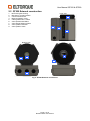
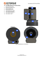
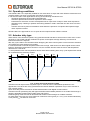
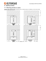
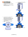
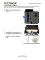
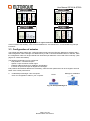
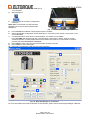
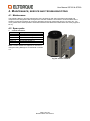
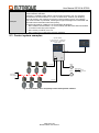
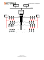
User Manual QT250 & QT800 Electrical Part-turn Valve Actuators Revision Date: 25.10.2013 User Manual QT250 & QT800 Revision history Rev Revision date 1 13.01.2011 2 3 4 5 22.01.2013 25.10.2013 Done by TEN Approved by Changes TMM TMM BN BN Changed company logo and front page image. Product update Technical data updated Referenced documentation Technical Manual_Eltorque Interfaces Eltorque Manager 2 Manual Page 2 of 24 Revision date: 25.10.2013 User Manual QT250 & QT800 TABLE OF CONTENTS 1. Introduction ................................................................................................................................................. 4 2. Specifications and manual operation ....................................................................................................... 5 2.1 Technical data .................................................................................................................................... 5 2.2 QT250 External construction .............................................................................................................. 7 2.3 QT800 External construction .............................................................................................................. 8 2.4 Operating conditions .......................................................................................................................... 9 2.5 Actuator duty type .............................................................................................................................. 9 2.6 Manual operation.............................................................................................................................. 11 3. Installation ................................................................................................................................................. 12 3.1 Mounting actuator on valve .............................................................................................................. 12 3.2 Electrical installation ......................................................................................................................... 14 3.3 Configuration of actuator .................................................................................................................. 15 3.4 Selecting correct configuration ......................................................................................................... 17 4. Maintenance, service and troubleshooting ........................................................................................... 18 4.1 Maintenance ..................................................................................................................................... 18 4.2 Spare parts ....................................................................................................................................... 18 4.3 Troubleshooting................................................................................................................................ 20 5. Appendix ................................................................................................................................................... 21 5.1 Ordering information ........................................................................................................................ 21 5.2 Terminology...................................................................................................................................... 21 5.3 Control system examples ................................................................................................................. 22 5.4 Notes ................................................................................................................................................ 24 Contact information: Eltorque AS N-7125 Vanvikan Norway Phone: +47 74 85 55 20 Fax: +47 74 85 55 12 Web: www.eltorque.com Page 3 of 24 Revision date: 25.10.2013 User Manual QT250 & QT800 1. INTRODUCTION Eltorque is a model range of electric valve actuators suitable for use in a wide variety of industrial environments. The Eltorque actuators are characterized by: Compact size and good torque to size/ weight ratio Flexible control interfaces for easy integration with a wide range of control systems Low power consumption Electronic configuration of speed, torque and other parameters Easy and cost effective installation Maintenance free The QT250 is suitable for use on part-turn valves with an operating torque below 250 Nm, while the QT800 is suitable for 250-800 Nm. Most part-turn valves utilize quarter-turn (90) movement, but the QT250 & 800 can easily be configured to an operation area within the range 0-359. During the purchasing process, it is important to consider the following parameters: Valve interface It must be checked that the spindle and valve mounting holes either fit directly onto the actuator or alternatively consider spindle adapters and valve brackets. Max operation torque The actuator must have sufficient torque to operate the valve in all applicable conditions. Closing time This is usually determined as a part of the process development. In some cases, the closing time should be as short as possible if the valve for example is shutting down a system in case of failure. In other cases it is desired with a longer closing time to avoid shock waves in pipe systems with high pressure or flow. The QT250 & 800 has an electronically configurable closing time. Remote Control The QT250 & 800 can be controlled remotely by different types of control: Digital (Open-Close) Analogue (4-20 mA) Modbus (Fieldbus, max 32 actuators per network) CANopen (Fieldbus, max 127 actuators per network) For more details about the functionality of these Control Interfaces, refer to the “Technical Manual Eltorque Interfaces”. Additionally, the actuator can be configured and controlled from a computer using a dedicated cable and software tool; Eltorque Manager 2. Page 4 of 24 Revision date: 25.10.2013 User Manual QT250 & QT800 2. SPECIFICATIONS AND MANUAL OPERATION 2.1 Technical data Torque Closing time Dimensions (HxWxD) Weight Valve flanges (Ref. ISO5211) Standard valve adapter Valve applications Operation temperature Color Encapsulation Control interfaces Position sensor Power supply Power consumption Over/ under temperature protection Manual operation * QT250 1.0 QT250 2.0 50-250 Nm* 0-90 movement: 13 -60 sec* 229 x 156 x 209 mm 12 kg QT800 1.0 QT800 2.0 160-800 Nm* 0-90 movement: 42 -180 sec* 333 x 200 x 239 21 kg F05, F07 & F10 F10 & F12 SQ17 SQ27 Butterfly or ball valves with part-turn operation Butterfly valve examples: DN50-DN200 PN16 DN250-DN350 PN16 -25 – 55 C -25 – 70 C -25 – 55 C -25 – 70 C Black Silver Black Silver IP68 (10m 72 hrs) Corrosion protected aluminium and steel enclosure Digital (Open-Close) Analogue (4-20 mA) Modbus (Fieldbus) CANopen (Fieldbus) Range: 360° - 0,4° resolution Position feedback not corrupted by power failure 110-240V AC/DC, 50/60 Hz, Max 200 VA At 250/ 800 Nm load: <100 W/ 200VA Standby: <20W/ 50VA Motor current is switched off in case of over-temperature Stator coils utilized as heating elements in case of low temperatures Manual override without tools, max 4 Nm torque 21 turns on hand wheel = 74 turns on hand wheel = 90 movement on valve 90 movement on valve Configurable using Eltorque Manager 2 Software. Page 5 of 24 Revision date: 25.10.2013 User Manual QT250 & QT800 QT250 QT800 Fig. 1: External, valve flange and spindle dimensions Page 6 of 24 Revision date: 25.10.2013 User Manual QT250 & QT800 2.2 QT250 External construction 1. 2. 3. 4. 5. 6. 7. 8. 9. Motor and gear housing. Bracket for control interface. Control Interface Box. Manuel operation cover. Cable gland holes 5 x M20 Valve spindle shaft SQ17 Valve flange fastening holes Valve position indicator Valve position scale Front view 4 3 2 1 Top view Bottom view 7 8 6 9 5 Fig. 2: QT250 External construction Page 7 of 24 Revision date: 25.10.2013 User Manual QT250 & QT800 2.3 QT800 External construction 1. 2. 3. 4. 5. 6. 7. 8. 9. 10. Motor and gear housing. Bracket for control interface. Control Interface Box. Manuel operation cover. External gear housing Cable gland holes 5 x M20 Valve spindle shaft SQ27 Valve flange fastening holes Valve position indicator Valve position scale Front view 4 3 2 1 5 Top view Bottom view 8 7 9 10 6 Fig. 3: QT800 External construction Page 8 of 24 Revision date: 25.10.2013 User Manual QT250 & QT800 2.4 Operating conditions The QT250 & 800 1.0 is especially suitable for use below deck on ships and other offshore vessels due to its compact design, low power consumption and robust construction. It can also be used in other applications as long as the following criterias are met: Operating temperature is kept within specified limits. Actuator is placed indoors and not exposed to direct sunlight. Protected from extensive corrosive atmospheres like on open deck of ships or other areas exposed to salt water spray. Cleaning or pollution with strong alkaline or acidic chemicals can also cause corrosion problems. Actuator must not be placed in hazardous areas where the presence of explosive atmospheres might cause explosion hazard. QT250 & 800 2.0 is approved for use on open deck for ships and other offshore vessels. 2.5 Actuator duty type When electric valve actuators operate, they generate internal heat due to thermal loss in motor and –control electronics. The QT250 and 800 combines low power consumption with high efficiency to ensure that internal thermal loss is kept low. Still, duty cycle needs to be considered when designing the valve control system to ensure that the actuators can operate the valves without over-heating. In case the actuator’s internal temperature becomes too high, it will send out an alarm signal via the control interface. Should the temperature continue to rise, the actuator will shut down the motor until temperature decreases to a safe level. To avoid problems with over-temperature alarms and actuator shutting down, duty cycle requirements should be considered before selecting actuator. trest tpos trest tpos Valve position tclose Time Fig. 4: Open-Close and positioning duty Actuators used for Open-Close duty either open or close the valves, intermediate positions are not approached. The valves are rarely operated and the interval between operations may be a few minutes or even several months. Open-Close duty will be relevant for QT250 & 800 actuators with Digital control interface. Actuators used for positioning duty will approach defined intermediate positions to set a static flow through a pipeline, applicable positions also include Open and Closed. Positioning duty will be relevant for QT250 & 800 actuators with Analogue or Fieldbus Interface. For both these duty types, the same maximum continuous running time (tclose or tpos) is 5 minutes followed by a rest period (trest) of minimum 5 minutes. Page 9 of 24 Revision date: 25.10.2013 Valve position tmod User Manual QT250 & QT800 trest Time Fig. 5: Modulating duty Modulating duty applies for actuators used on control valves where accurate and quick control of flow, level, temperature etc. is desired. The actuators will be controlled automatically by a regulator or PLC depending on process data from sensors like flow meters, level- and temperature sensors, and some applications might require valve position adjustments within intervals of a few seconds. This kind of operation puts higher demand on the actuator in terms of accuracy, wear resistance, low internal heat generation and good heat dissipation. Modulating duty is relevant for QT250 & 800 with Analogue or Fieldbus Interfaces. Running time for modulating duty is limited by the relative on-time: tmod / trest < 0,5. The duty type limitations stated above applies for maximum operation temperature, and torque, see section 2.1. If operating temperatures and or torque are lower, the actuator can be operated more than the duty type limitations stated above. Page 10 of 24 Revision date: 25.10.2013 User Manual QT250 & QT800 2.6 Manual operation In case of power failure, control system error or another fault preventing normal operation of the actuator, it can be operated manually without the need of additional tools: 1. Remove hand-wheel cover by grabbing the tabs and pulling it straight up. 1 Fig. 6: Removing hand-wheel cover 2. 3. 4. Turn hand-wheel Clockwise to close or Counter-clockwise to open valve. Valve position can be seen on the visual indicator in the centre of the hand-wheel and reference is made to the scale (D). When Manual Operation is completed, refit hand wheel cover by pressing it down until it stops against the actuator’s top cover. 3 2 2 Fig. 7: Manual operation features Page 11 of 24 Revision date: 25.10.2013 User Manual QT250 & QT800 3. INSTALLATION 3.1 Mounting actuator on valve Before mounting actuator, please make sure there is sufficient space for installation, service and manual operation above and around it: Fig. 8: Space for installation, service and manual operation Page 12 of 24 Revision date: 25.10.2013 User Manual QT250 & QT800 1. 2. Apply grease on valve spindle to ease mounting and avoid corrosion. Lift actuator onto valve; align its valve adapter with the valve spindle and lower actuator onto valve flange. Note: Keep hands away from the valve flanges to avoid crushing damages. 1 Fig. 9: Lowering actuator onto valve. 3. 4. 5. Use hand wheel to turn actuator and align fastening holes of the valve flanges. Note: In order to achieve optimal functionality of valve position indicator, actuator should be positioned as shown in Fig. 10 below. Insert fastening screws and use washers according to ISO5211 standard and valve vendor’s specifications. Tighten fastening screws to the specified torque. Fig. 11: Aligning fastening holes and inserting screws. Fig. 10: Correct orientation of actuator. Page 13 of 24 Revision date: 25.10.2013 User Manual QT250 & QT800 3.2 Electrical installation Note: Electrical installation can only be designed and made by personnel with the appropriate skills and competence. Ensure all such work is done according to applicable laws and regulations. 1. 2. Loosen control interface fastening screws, 6 pcs. Remove control interface box by pulling is straight out. 1 Fig. 12: Removing control interface box X1 1 2 3 4 5 6 7 8 Make sure fuses are disconnected before connection of power supply cables is started. 3. Install the power supply cables through the cable glands on the right side and connect them to the L, N and G/ PE terminals. 4. Install the control signal cables through the cable glands on the left and connect them according to X1 according to specification below. 4 L N G L N G 3 Fig. 13: Connection terminals location. Fig. 14: Operation of spring loaded terminals Page 14 of 24 Revision date: 25.10.2013 User Manual QT250 & QT800 CANopen Control Interface Digital Control Interface 1 2 3 4 Closed Open Alarm GND 6 7 8 Bridge for terminal resistor Common Out 5 GND Open 4 B (TxD-/ RxD-) Close 3 A (TxD+/ RxD+) Common In 2 6 7 8 Modbus Control Interface Incoming 1 5 CAN_L 8 CAN_H Not in use 7 1 2 3 4 5 Outgoing GND Not in use 6 B (TxD-/ RxD-) Alarm - 5 Outgoing A (TxD+/ RxD+) Alarm + 4 Bridge for terminal resistor Analogue Out - 3 CAN_L Analogue Out + 2 CAN_H Analogue In - 1 GND Analogue In + Incoming GND Analogue Control Interface 6 7 8 Fig. 15: Control signal connection terminals. Control Interface functionality, cable recommendations etc. are described in ”Technical Manual_Eltorque Interfaces”. 3.3 Configuration of actuator The QT250 and 800 actuators are configured electronically using the Eltorque Manager 2 software and a USB configuration cable. Manager 2 is distributed by e-mail or can be downloaded from our website, while the configuration cable can be purchased from local Eltorque distributor or the head office in Norway. (See page 2 for contact information) The following parameters can be configured: End positions – Closed and Open. Speed, Torque and Near Closed region. Fieldbus address/ Node ID for CANopen and Modbus. Inversion of input and output for Digital and Analogue. End positions and fieldbus address are mandatory, while the other parameters can be changed to achieve better valve control performance. 1. Install Eltorque Manager 2 and if required driver for configuration cable on your computer. Driver: Manager 2 Installation file: Fig. 16: Eltorque Manager 2 installation files. Page 15 of 24 Revision date: 25.10.2013 User Manual QT250 & QT800 2. 3. Connect configuration cable to a USB port on your computer. Start Manager 2 X1 1 2 3 4 5 6 7 8 Connect cable to Actuator’s configuration connector. Note: Make sure actuator is powered before attempting to connect actuator with Eltorque Manager 2. L N G L N G 4. 4 Fig. 17: Connection of configuration cable. Press Connect to establish communication with the actuator. Select appropriate configuration values depending on valve and control system, see section 3.4 for more information. 7. Use Hand-Wheel to move valve to closed position, see section 2.6 for details. Press Set C&O and Closed is set to the actual position, while Open is set 90 away in counter clockwise direction. If further adjustment of end positions are required, move actuator to desired position and press Set Closed or Set Open. 8. Press Open to open valve and check that actuator operates correctly. 9. Press Close to close valve again. 10. Disconnect configuration cable and refit control interface. 5. 6. 6 6 9 8 6 5 7 Fig. 18: Eltorque Manager 2 screenshot. For more information about the functionality of the software, please refer to the Eltorque Manager 2 Manual. Page 16 of 24 Revision date: 25.10.2013 User Manual QT250 & QT800 3.4 Selecting correct configuration The QT250 & 800 offers an easy but advanced configuration set-up, which allows accurate adjustments depending on valve and control system characteristics. Please consider the following items when selecting configuration values: Set torque values according to valve’s torque specifications with a suitable safety margin. If torque is set too high, the valve might be damaged in case it is blocked by e.g. foreign objects inside pipe. On butterfly valves, the maximum torque is required to move disc in and out of the gasket in closed position. Hence should only the torque in the near closed region be set according to the valve’s specified operation torque. Torque in the travel area will be considerably lower. Ball valves tend to have a constant torque through the whole operation area, but the maximum torque is reached when the valve movement starts, so called “breakaway” torque. 96-100%, area not configurable. Fixed accel-/ decelaration ramp. Torque is the same as in the travel area. Status = Open Open Speed and running torque options: 20-100% of max Holding torque options: 0-100% of max 100 % C N lo or si m ng al re gi pe O on ni ng Near closed area Configurable 0-15% Status Closed 0-2% Near Closed 0% Speed and running torque options: 20-100% of max Holding torque options: 0-100% of max Fig. 19: Torque, speed and region settings. - - Under Fieldbus settings you can set the Node ID of actuators with CANopen or Modbus Control Interface. It is important that all actuators in the network have a unique Node ID and that it is set correctly according to the layout of the control system. In case the actuator has Analogue or Digital interface, the Fieldbus settings will be replaced by settings related to calibration and inversion of input and output signals. Refer to Technical Manual_Eltorque Interfaces for more information. Page 17 of 24 Revision date: 25.10.2013 User Manual QT250 & QT800 4. MAINTENANCE, SERVICE AND TROUBLESHOOTING 4.1 Maintenance The QT250 & 800 is in principle maintenance free; all bearings and gears are lifetime lubricated and components are designed to last throughout the actuator’s lifetime. It is however recommended that the actuator is inspected regularly to reveal any damages caused by mechanical impact, corrosion etc. Top cover gasket and manual operation shaft seal should be lubricated with suitable lubricants if they appear to be dry. 4.2 Spare parts 1. Control Interfaces: Part No. Description 100.030.2 QT250/800 Analog 1.0 100.020.2 QT250/800 CanOpen 1.0 100.021.2 QT250/800 CanOpen 2.0 100.010.2 QT250/800 Digital 1.0 100.011.2 QT250/800 Digital 2.0 100.040.2 QT250/800 Modbus 1.0 Note: If control interface is replaced, it must be reconfigured using Manager 2 as described in section 3.3. 1 Fig. 20: Control interface. Page 18 of 24 Revision date: 25.10.2013 User Manual QT250 & QT800 Item Part No. Description 1 2 30003 35002 3 40017 PROTECTIVE COVER Ø115 POSITION INDICATOR ARROW POSITION INDICATOR 4 10013 5 6 40014 40018 7 20008 8 9 35003 40015 10 10012 11 20006 12 45017 13 10014 14 15 20003 10026 16 10025 17 10024 18 19 30002 100.003 20 45009 21 35004 22 10010 23 25005 HEX SCREW M5 X 12 DIN912 CABLE BUSHING PLUG 24 20005 SHAFT SEAL TR615-6 SS 25 26 100.002 45008 ASSEMBLY STATOR ROTOR Ø101-48P-0,4T 27 28 25007 10018 MOLEX 6 PIN CHASSIS HEX SCREW M4 X 8 DIN 7984 A4 HEX SCREW M4 X 8 DIN912 WHEEL A1 Ø117 LID A1 PROFILE Ø131,5 (INCL.SHAFT SEAL) O-RING 114,5 X 3 0-90 DEG SCALE BRACKET FOR ELBOX(BLACK) NUT M4 DIN934 GASKET BRACKET CAPSULE CONTACT HOLDER HEX SCREW M5 X 20 DIN912 A4 O-RING Ø129,5 X 3 HEX SCREW M5 X 8 DIN7984 SPRING WASHER M5 DIN127B HEX SCREW M6 X 60 DIN7984 STRIPS 430 X 4,8 BOTTOM & ENCODER ASSEMBLY CAPSULE A1 BLACK Ø131 X 183 ELTORQUE MARK Fig. 21: Actuator spare parts Page 19 of 24 Revision date: 25.10.2013 User Manual QT250 & QT800 4.3 Troubleshooting Problem description No response from actuator either on the control system or if you connect with Manager 2. No change in resistance on the hand wheel if you cycle the power supply. Actuator’s alarm output is active, on a fieldbus system it gives torque alarm. The actuator attempts to move valve when a control signal is given. Actuator is able to operate the valve but the operation time is longer or shorter than desired. Actuator’s alarm output is active, on a fieldbus system it gives temperature alarm. The actuator responds normally to control signals. Actuator’s alarm output is active, on a fieldbus system it gives temperature alarm. The actuator does not respond to control signals. Indicator LED is “normal”. The actuator does not respond to control signals. On a fieldbus system, the actuator is not available. Actuator with fieldbus interface does not respond to control signals. The actuator responds normally when tested with Manager 2. Actuator with digital or analog interface does not respond normally to control signals. The actuator responds normally when tested with Manager 2. Actuator does not respond neither to control signals nor when tested with Manager 2. Actuator power supply is verified with voltage meter. After replacement of interface, actuator does not operate correctly. Cause & solution No power supply, check fuses and wiring. Supply voltage can be checked using a voltage meter. L-N voltage should be 230 V AC ± 20%. Valve operation torque is too high, please check torque by manual operation. Be aware that foreign objects in the pipe can block the valve and that valve torque changes over time. OR Actuator torque has been set too low, increase it by using Eltorque Manager 2 as described in section 3.3. On fieldbus control systems, torque can be adjusted via the fieldbus communication. Change actuator’s speed by using Eltorque Manager 2 as described in section 3.3. On fieldbus control systems, speed can be adjusted via the fieldbus communication. Actuator’s internal temperature is 10 C or less from the motor current shut-down limit. If possible, allow actuator to cool down by leaving it in standby mode for 15 minutes or more. Actuator has over-heated and the motor current is shut down to prevent damage. Make sure surrounding temperature is within limits and that the duty type requirements are followed. See section 2 for more details. Faulty control system, please ask system vendor for support. OR Problem with control signal wiring, please contact local Eltorque agent for support. Incorrect fieldbus settings, please check configuration with Manager 2. OR Fieldbus control system is not wired or configured correctly. Incorrect digital or analog inversion settings, please check configuration with Manager 2. OR Digital or analog control system is not wired or configured correctly. Defective control interface, must be replaced. Interface has not been configured correctly, please refer to section 3.3. Contact local Eltorque agent for support if required. Page 20 of 24 Revision date: 25.10.2013 User Manual QT250 & QT800 5. APPENDIX 5.1 Ordering information Part number 250.020.1 250.021.1 250.110.1 250.111.1 250.130.1 250.140.1 800.020.1 800.021.1 800.110.1 800.111.1 800.130.1 800.140.1 Description QT250 1.0 with CANopen Interface QT250 2.0 with CANopen Interface QT250 1.0 with Digital Interface QT250 2.0 with Digital Interface QT250 1.0 with Analog Interface QT250 1.0 with Modbus Interface QT800 1.0 with CANopen Interface QT800 2.0 with CANopen Interface QT800 1.0 with Digital Interface QT800 2.0 with Digital Interface QT800 1.0 with Analog Interface QT800 1.0 with Modbus Interface 5.2 Terminology Term Valve Valve actuator Valve flange Valve adapter Control Interface Configuration Hazardous area PLC Digital Control Analogue Control Fieldbus Control Modbus Description A valve is a device that regulates the flow of materials (gases, fluidized solids, slurries, or liquids) by opening, closing, or partially obstructing various passageways. This manual mostly refers to quarter-turn valves with a 90 degrees movement between Closed and Open position. An electric device for operation of valves in various process control systems. The surface of the valve which the actuator is fastened to. Most commonly it is holes for 4 screws, where hole size and distance between them is defined in EN ISO 5211 standard. A device used to connect the actuator to the valve spindle/ stem. Electronic device controlling the valve actuator according to signals from an overall control system. e.g. PLC or other type of electronic controller. The set-up of parameters, which affects the actuator’s performance and behaviour. Area in which the permanent or periodical presence of explosive substances causes a risk of explosion. A Programmable Logic Controller is a digital computer used for automation of industrial processes, such as control of machinery on factory assembly lines, measurement and control of process plants etc. Simple control utilizing relays, on/ off switches and indicators. Allows only Open or Closed functionality for a valve actuator. Step-less control utilizing analogue current or voltage signals, e.g. 4-20 mA, 0-10 V etc. Allows positioning of the valve actuator between Open and Closed. A fieldbus is an industrial computer network for real-time distributed control of various devices, including valve actuators. When Eltorque valve actuators are controlled by Fieldbus, the functionality is extended in terms of positioning, commands, feedback and configuration. The Eltorque Modbus interface is using RS-485 serial communication utilizing the Modbus protocol. Modbus is a fieldbus which allows communication with max 31 actuators connected to the same “master-slave” network. “Master-slave” means that the Modbus controller is a master which actively sends commands and requests to the “slave actuators”. Page 21 of 24 Revision date: 25.10.2013 User Manual QT250 & QT800 Term CANopen Description The Eltorque CANopen interface is using the CAN (Controller Area Network) communications standard. CANopen is a fieldbus which allows communication between max 127 actuators connected to the same network. It is not a “master-slave” network (ref. Modbus), hence all nodes in the network can actively send messages at their own initiative. The communication is prioritized, meaning that urgent messages are transmitted and received before information with lower priority. Compared to Modbus, CANopen has the following advantages: More reliable communication, i.e. it is more likely that the information transmitted is received correctly by the recipient. More nodes pr network, max 127. More control and configuration features available. 5.3 Control system examples Operator Station 17" touch monitor + compact PC Mounted in PLC cabinet door Master panel ETHERNET LOOP 1 Digital IO PUMP 1 CAN OPEN PUMP 2 Pump control Start / stop command Started / stopped feedback Failure feedback Power supply 230VAC 50/60Hz CAN OPEN Fig. 22: Stand-alone valve and pump control with operator stations. Page 22 of 24 Revision date: 25.10.2013 User Manual QT250 & QT800 Main control system 1 Main control system 2 ETHERNET Ethernet to CANopen Converter for Valve Control Power supply 230VAC 50/60Hz (serial power) Power supply 230VAC 50/60Hz (serial power) CANopen Loop 1A Loop 1B Loop 2A Loop 2B Loop 3A Loop 3B Loop 4A Loop 4B Fig. 23: Valve control system as an integrated part of a larger control system. Page 23 of 24 Revision date: 25.10.2013 User Manual QT250 & QT800 5.4 Notes Page 24 of 24 Revision date: 25.10.2013