1
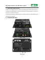
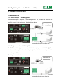
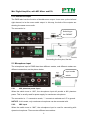
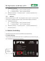
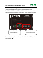
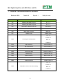
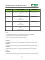
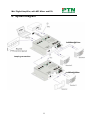
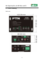
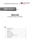
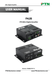
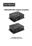
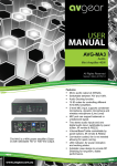
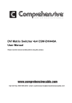
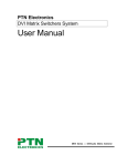
Mini Digital Amplifier, with MIC Mixer and EQ USER MANUAL PA2B Mini Digital Amplifier, with EQ/Mixer Index: 1. 2. 3. 4. 5. 6. 7. 8. 9. General Instruction ................................................................ 2 Product Picture....................................................................... 2 Features .................................................................................. 3 Specification .......................................................................... 4 Audio Connection .................................................................. 5 Buttons Controlling ............................................................... 7 RS232 Communication Protocol: .......................................... 9 System Diagram................................................................... 11 Panel Drawing ..................................................................... 12 1 Mini Digital Amplifier, with MIC Mixer and EQ 1. General Instruction PA2B is a small digital amplifier (Class-D), with EQ control and MIC mixer function. It is compact-size but powerful functions, including the bridge connection, dual-mono, EQ control, microphone mixer etc. It has a good application in different places, including classroom, small meeting room, lecture hall, bar, pub etc. 2. Product Picture Front Panel Rear Panel Top Panel 2 Mini Digital Amplifier, with MIC Mixer and EQ 3. Features 2x20Watt@4Ohm as the default amplifier output. Bridge connection function. The user can switch the PA2 to be 1x40Watt@8Ohm by bridge connection. Dual-mono function. The user can sum up the stereo audio to two times mono audio. Microphone mixer function. The microphone will be mixed to the line audio output, and separately controllable. MIC input supports 48V phantom power, condenser microphone available. MIC port with balance switching, can support balance/unbalance signal, suppress the external noise effectively. Ducking power technology. It keeps detecting the audio and MIC input, and reducing the power consumption when there is no input coming. Ultra low inrush current, no need for power sequencing. This allows multiple PA2B to be powered on simultaneously without overloading power circuits. Convection cooled, fan is not needed. Two stereo audio inputs, switchable by button, remote or RS232. Fast switching speed. It is the high speed for the good performance. Volume/Bass/Treble controllable by buttons or RS232 Line audio output, with volume controllable. Optional control by IR remote. Extensibility: It can be controlled by PTN panel (WP8 & WP19), optional function. Antistatic case design: providing good protection for long-term and stable performance LED indicator, for power and working status. 3 Mini Digital Amplifier, with MIC Mixer and EQ 4. Specification Audio Input Audio Output 2 stereo audio, Input 1 amplifier, Output 1 MIC 1 stereo audio 2 RCA 1 captive screw connector Input Connector 1 3.5mm jack Output Connector 1 3.5mm jack 1 captive screw connector, Input Impedance >10KΩ Output Impedance 50Ω/stereo, 4~8Ω/Amplifier 20Hz ~ 20KHz CMRR >70dB@20Hz~20KHz 80dB at maximum output Bandwidth 20Hz ~ 25KHz >75dB@20Hz to 20KHz THD + Noise Audio General Frequency Response SNR Stereo Channel 1%@1KHz, Separation Voltage Gain 0.3%@20KHz nominal level 32dB Power Output 2x20 Watts (4 Ohms) Pin Configurations 2 = TX, 3 = RX, 5 = GND Control Parts RS-232, 9-pin female D Serial Control Port connector IR Remote Optional IR remote Options TCP/IP control by PTNET(PTN's programmable interface) NOTE: All nominal levels are at ±10%. 4 at Mini Digital Amplifier, with MIC Mixer and EQ 5. Audio Connection 5.1 Audio Output 5.1.1 Default output: 2x20Watt@4Ohm The default output of amplifier is 2x20Watt@4Ohm. So, the user can connect the amplifier output in the regular way. As the picture below: Switching to the “STEREO” Connecting the four pins, like this 5.1.2 Bridge connection: 1x40Watt@8Ohm The PA2B has the bridge connection, to double the output power at 1x40Watt@8Ohm. It will sum up the input left channel and input right channel to be mono output, and the power is up to 40Watt. The bridge connection is: Switching to the “BRIDGE” Connecting the two pins, like this 5 Mini Digital Amplifier, with MIC Mixer and EQ 5.1.3 Dual-mono output: The PA2B also has the function of double-mono output. It can sum up the left and right channel, to be the mono audio output. In this way, the both of the outputs are showing the same mono audio. The connection is: Switching to the “MONO” Connecting the four pins, like this 5.1 Microphone input The microphone input of PA2B has three different modes, and different modes use different connections, as the picture below: Input modes switch. 5.2.1 48V phantom power input When the switch turns to “48V”, the microphone input will provide a 48V phantom power. This is usually used for power supply for condenser microphone. The connection is: “+” connects to anode, “-” connects to cathode and “╧” to ground. NOTICE: In this mode, only condenser microphone can be connected with. 5.2.2 MIC input When the switch turns to “MIC”, the microphone input is used for connecting with dynamic microphone. There are two different connections: 6 Mini Digital Amplifier, with MIC Mixer and EQ 1) Unbalanced connection: a) “-” connects to signal, “+” and “╧” connect to ground. b) “+” connects to signal, “-” and “╧” connect to ground. Balanced connection: “+” connects to anode, “-” connects to cathode and “╧” 2) connects to ground. 5.2.3 LINE input When the switch turns to “LINE”, the microphone input is used for connecting with normal audio or wireless microphone output. There are two different connections: 1) 2) Unbalanced connection: a) “-” connects to signal, “+” and “╧” connect to ground. b) “+” connects to signal, “-” and “╧” connect to ground. Balanced connection: “+” connects to anode, “-” connects to cathode and “╧” connects to ground. 6. Buttons Controlling The buttons provides the control of volume/EQ control and switching. 6.1 Audio switching There are two switchable stereo audio inputs, one 2xRCA input, and one 3.5mm jack input, switchable through the buttons as below: Source Selection 7 Mini Digital Amplifier, with MIC Mixer and EQ 6.2 Volume/EQ controlling The line volume and Microphone volume can be controlled by the buttons. The MIC Volume/LINE volume/LINE bass/LINE treble will be selected by the buttons, and controlled up/down/mute by the function buttons. Please check the picture below: Select the function from Turn down/up the level. this menu in advance Or mute the line volume For example, to turn up the line volume, you should select the “LINE” first, and then press the button “ ”. 8 Mini Digital Amplifier, with MIC Mixer and EQ 7. RS232 Communication Protocol: Baud rate: 9600 Command Data bit: 8 Stop bit: 1 Parity bit: none Function Description Feedback Code 1A1. Switching the audio to input 1 A: 1 -> 1 2A1. Switching the audio to input 2 A: 2 -> 1 0A0. Mute Audio of MIC and Line out Mute Audio 1A0. Mute audio of MIC Mute MIC 2A0. Mute audio of line out Mute LIN 0A1. UnMute Audio UnMute Audio A: 1 -> 1 Volume: 30 600% Checking the working status Bass: 00 Treble: 00 601% MIC volume up Volume of MIC: 51 602% MIC volume down Volume of MIC: 51 603% Line volume up Volume of LINE: 51 604% Line volume down Volume of LINE: 51 605% Bass level up Bass of LINE: 04 606% Bass level down Bass of LINE: 04 607% Treble level up Treble of LINE: 04 608% Treble level down Treble of LINE: 04 A: 1 -> 1 Volume: 50 609% Initialization, back to the default setting Bass: 04 Treble: 04 9 Mini Digital Amplifier, with MIC Mixer and EQ Command Function Description Feedback Code 5[x][x]% Preset MIC volume, [xx] arranges from [00] to Volume of MIC: 50 [60]. 61 degrees in total. 7[x][x]% Preset line volume, [xx] arranges from [00] to Volume of LINE: 50 [60]. 61 degrees in total. 8[x][x]% Preset the bass level, [xx] arranges from [00] Bass of LINE: 04 to [08]. 9 degrees in total. 9[x][x]% Preset the treble level, [xx] arranges from [00] Treble of LINE: 04 to [08]. 9 degrees in total. Notice: 1: The letter inside bracket [ ] is the variable code, which is the changeable. 2: The bracket [ ] is not included to the RS232 commands. 3: Any dot “.” after the letters is part of the commands. Example 1 Switching the input 2 to the line out. We should send the RS232 command: [2A1.] Example 2 Turning up the volume of line audio. We should send the RS232 command: [603%] Example 3 Preset the MIC volume to be “21” degree. We should send the RS232 command: [521%] Example 4 Checking the working status of PA2. We should send the RS232 command: [600%] 10 Mini Digital Amplifier, with MIC Mixer and EQ 8. System Diagram 2x20Watt@4Ohm Looping connection 1x40Watt@8Ohm 11 Mini Digital Amplifier, with MIC Mixer and EQ 9. Panel Drawing Unit: mm 12