1
ÎÎ GE Fanuc Automation Programmable Control Products Series 90 Sequential Function Chart Programming Language User’s Manual GFK-0854A October 1994 GFL-002 Warnings, Cautions, and Notes as Used in this Publication Warning Warning notices are used in this publication to emphasize that hazardous voltages, currents, temperatures, or other conditions that could cause personal injury exist in this equipment or may be associated with its use. In situations where inattention could cause either personal injury or damage to equipment, a Warning notice is used. Caution Caution notices are used where equipment might be damaged if care is not taken. Note Notes merely call attention to information that is especially significant to understanding and operating the equipment. This document is based on information available at the time of its publication. While efforts have been made to be accurate, the information contained herein does not purport to cover all details or variations in hardware or software, nor to provide for every possible contingency in connection with installation, operation, or maintenance. Features may be described herein which are not present in all hardware and software systems. GE Fanuc Automation assumes no obligation of notice to holders of this document with respect to changes subsequently made. GE Fanuc Automation makes no representation or warranty, expressed, implied, or statutory with respect to, and assumes no responsibility for the accuracy, completeness, sufficiency, or usefulness of the information contained herein. No warranties of merchantability or fitness for purpose shall apply. The following are trademarks of GE Fanuc Automation North America, Inc. Alarm Master CIMPLICITY CIMPLICITY90-ADS CIMPLICITY PowerTRAC CIMSTAR GEnet Genius Genius PowerTRAC Helpmate Logicmaster Modelmaster ProLoop PROMACRO Series One Series Three Series Five Copyright 1989–1994 GE Fanuc Automation North America, Inc. All Rights Reserved Series Six Series 90 VuMaster Workmaster Preface t Logicmaster 90 programming software is used to configure and program the Series 90 programmable controllers. This manual describes how to use sequential function chart (SFC) version of Logicmaster software to program your logic and create an application program for your programmable controller. t Content of This Manual For 90-70 users, this manual is supplementary in content to the Logicmaster 90-70 Programming Software User’s Manual, GFK-0263, and to the Series 90-70 Programmable Controller Reference Manual, GFK-0265. You will need to refer to these Logicmaster 90-70 manuals in order to become familiar with the features of Logicmaster 90-70 programming software. For 90-30 users, this manual is supplementary in content to the Logicmaster 90-30 Programming Software User’s Manual, GFK-0466, and to the Series 90-30 Programmable Controller Reference Manual, GFK-0467. You will need to refer to these Logicmaster 90-30 manuals in order to become familiar with the features of Logicmaster 90-30 programming software. The Series 90 Sequential Function Chart Programming Language User’s Manual, GFK-0854A, contains only that information which is unique to the sequential function chart version of Logicmaster 90 software. It does not repeat material found in either the User’s Manuals or the Reference Manuals that is common to both the SFC and RLD versions of Logicmaster 90 software. This is the second edition of the Series 90 Sequential Function Chart Programming Language User’s Manual, GFK-0854A. It contains the following chapters and appendixes. Chapter 1. Introduction: provides an introduction to sequential function chart language and describes what you will need in order to create an application program. Chapter 2. Understanding SFC Language: provides an overview of sequential function chart (SFC) language. Chapter 3. Sequential Function Chart Editor: describes SFC program blocks, how to insert/edit an SFC network, and the functions available in the SFC Editor. Chapter 4. Printing SFC Blocks: describes a typical printout of an SFC network and provides examples of each section of the printout. Appendix A. Common User Errors: lists common user errors. GFK-0854A iii Preface Revisions to This Manual Changes made to this manual reflect the features of this release of SFC (October 1994), primarily the inclusion of a 90-30 version of SFC. When there are differences between the 90-30 and the 90-70 versions (such as SFC subroutine capabilities), these differences are noted in the sections discussing the features wherein they differ. Additionally, clarifications and corrections have been made where necessary. Related Publications t Series 90 -70 Programmable Controller Installation Manual (GFK-0262). t 90-70 Programming Software User’s Manual (GFK-0263). Logicmaster t Series 90 -70 Programmable Controller Reference Manual (GFK-0265). t Series 90 -30 Programmable Controller Installation Manual (GFK-0356). t 90-30 Programming Software User’s Manual (GFK-0466). Logicmaster t Series 90 -30 Programmable Controller Reference Manual (GFK-0467). We Welcome Your Comments and Suggestions At GE Fanuc Automation, we strive to produce quality technical documentation. After you have used this manual, please take a few moments to complete and return the Reader ’s Comment Card located on the next page. Linda Edenfield CustomerDocumentationProcessManager David Bruton Sr. Technical Writer iv Series 90 Sequential Function Chart Programming LanguageUser’s Manual – October 1994 GFK-0854A Contents Chapter 1 Chapter 2 Chapter 3 Introduction . . . . . . . . . . . . . . . . . . . . . . . . . . . . . . . . . . . . . . . . . . . . . . . 1-1 SFC Defined . . . . . . . . . . . . . . . . . . . . . . . . . . . . . . . . . . . . . . . . . . . . . . . . . . SFC in 90-30 and SFC in 90-70 Logicmaster . . . . . . . . . . . . . . . . . . . . . . . . What You Will Need . . . . . . . . . . . . . . . . . . . . . . . . . . . . . . . . . . . . . . . . . . . MS-DOS Version . . . . . . . . . . . . . . . . . . . . . . . . . . . . . . . . . . . . . . . . . . . . . . . Installing the Software . . . . . . . . . . . . . . . . . . . . . . . . . . . . . . . . . . . . . . . . . . Help Screens . . . . . . . . . . . . . . . . . . . . . . . . . . . . . . . . . . . . . . . . . . . . . . . . . . Key Functions . . . . . . . . . . . . . . . . . . . . . . . . . . . . . . . . . . . . . . . . . . . . . . . . . Softkey Directory . . . . . . . . . . . . . . . . . . . . . . . . . . . . . . . . . . . . . . . . . . . . . . 1-1 1-1 1-1 1-2 1-2 1-2 1-2 1-2 Understanding SFC Language . . . . . . . . . . . . . . . . . . . . . . . . . . . . . . . 2-1 RLD and SFC . . . . . . . . . . . . . . . . . . . . . . . . . . . . . . . . . . . . . . . . . . . . . . . . . . Steps . . . . . . . . . . . . . . . . . . . . . . . . . . . . . . . . . . . . . . . . . . . . . . . . . . . . . . . . Transitions . . . . . . . . . . . . . . . . . . . . . . . . . . . . . . . . . . . . . . . . . . . . . . . . . . . Series 90 PLC Scan Cycle . . . . . . . . . . . . . . . . . . . . . . . . . . . . . . . . . . . . . . . . SFC Evolution . . . . . . . . . . . . . . . . . . . . . . . . . . . . . . . . . . . . . . . . . . . . . . . . . Examples of Sequential Function Charts . . . . . . . . . . . . . . . . . . . . . . . . . . . Basic Control Structures . . . . . . . . . . . . . . . . . . . . . . . . . . . . . . . . . . . . . . . . Source and Destination Connectors . . . . . . . . . . . . . . . . . . . . . . . . . . . . . Examples of Basic Control Structures . . . . . . . . . . . . . . . . . . . . . . . . . . . . . Rules for Basic Control Structure . . . . . . . . . . . . . . . . . . . . . . . . . . . . . . . . . 2-1 2-3 2-4 2-6 2-7 2-9 2-10 2-13 2-14 2-16 Sequential Function Chart Editor . . . . . . . . . . . . . . . . . . . . . . . . . . . . 3-1 Section 1: SFC Program Blocks . . . . . . . . . . . . . . . . . . . . . . . . . . . . . 3-2 Step Timers . . . . . . . . . . . . . . . . . . . . . . . . . . . . . . . . . . . . . . . . . . . . . . . . . . . Step Fault Bits . . . . . . . . . . . . . . . . . . . . . . . . . . . . . . . . . . . . . . . . . . . . . . . . . Step Flags . . . . . . . . . . . . . . . . . . . . . . . . . . . . . . . . . . . . . . . . . . . . . . . . . . . . . Format of an SFC Block . . . . . . . . . . . . . . . . . . . . . . . . . . . . . . . . . . . . . . . . . Preprocessing and Postprocessing Logic . . . . . . . . . . . . . . . . . . . . . . . . . . . Programming SFC Step Action Logic . . . . . . . . . . . . . . . . . . . . . . . . . . . . . Selecting the Block’s Language . . . . . . . . . . . . . . . . . . . . . . . . . . . . . . . . . . Changing the Display Mode . . . . . . . . . . . . . . . . . . . . . . . . . . . . . . . . . . . . . Section 2: Inserting/Editing an SFC Network Topology . . . . . . . Grid Organization . . . . . . . . . . . . . . . . . . . . . . . . . . . . . . . . . . . . . . . . . . . . . Moving the Cursor . . . . . . . . . . . . . . . . . . . . . . . . . . . . . . . . . . . . . . . . . . . . . Naming Steps, Transitions, and Connectors . . . . . . . . . . . . . . . . . . . . . . Inserting/Editing an Example SFC Network . . . . . . . . . . . . . . . . . . . . . . . Deleting an Element . . . . . . . . . . . . . . . . . . . . . . . . . . . . . . . . . . . . . . . . . . Open/Delete Space Functions . . . . . . . . . . . . . . . . . . . . . . . . . . . . . . . . . . . . Exiting Insert or Edit Mode . . . . . . . . . . . . . . . . . . . . . . . . . . . . . . . . . . . . . . Displaying Errors in the Network . . . . . . . . . . . . . . . . . . . . . . . . . . . . . . . . Storing Changes to an SFC Block . . . . . . . . . . . . . . . . . . . . . . . . . . . . . . . . . GFK-0854A Series 90 Sequential Function Chart Programming Language User’s Manual – October 1994 3-3 3-3 3-3 3-4 3-6 3-7 3-8 3-10 3-11 3-15 3-17 3-18 3-19 3-35 3-36 3-44 3-44 3-45 v Contents Section 3: Search Function ................................ Enabling the Search Function . . . . . . . . . . . . . . . . . . . . . . . . . . . . . . . . . . . . 3-47 Goto . . . . . . . . . . . . . . . . . . . . . . . . . . . . . . . . . . . . . . . . . . . . . . . . . . . . . . . . . 3-51 Ending the Search . . . . . . . . . . . . . . . . . . . . . . . . . . . . . . . . . . . . . . . . . . . . . 3-51 Section 4: Comments ..................................... Section 5: Options Related to SFC Blocks ................... GFK-0854A 3-53 3-53 Configuring Multiple Languages . . . . . . . . . . . . . . . . . . . . . . . . . . . . . . . . . 3-55 ............................... 3-57 SFC_RESET . . . . . . . . . . . . . . . . . . . . . . . . . . . . . . . . . . . . . . . . . . . . . . . . . . 3-58 Toggles and Overrides . . . . . . . . . . . . . . . . . . . . . . . . . . . . . . . . . . . . . . . . . . 3-59 Evolution History . . . . . . . . . . . . . . . . . . . . . . . . . . . . . . . . . . . . . . . . . . . . . . 3-60 Goto ........................................................ 3-61 Setting the Time Base and Step Time Limits for an SFC Block . . . . . . . . . 3-62 Single Sweep Debug . . . . . . . . . . . . . . . . . . . . . . . . . . . . . . . . . . . . . . . . . . . 3-64 Section 7: Program Utility Functions . . . . . . . . . . . . . . . . . . . . . . . . Appendix A 3-52 Fault Logging for Out-of-Limit Step Times . . . . . . . . . . . . . . . . . . . . . . . . Section 6: Debug Functions Chapter 4 3-46 3-65 Loading from the PLC to the Programmer . . . . . . . . . . . . . . . . . . . . . . . . . 3-65 Storing to the PLC from the Programmer . . . . . . . . . . . . . . . . . . . . . . . . . . 3-65 Verifying a Program with the PLC . . . . . . . . . . . . . . . . . . . . . . . . . . . . . . . . 3-67 Printing SFC Blocks . . . . . . . . . . . . . . . . . . . . . . . . . . . . . . . . . . . . . . . . 4-1 Sample SFC Network Page . . . . . . . . . . . . . . . . . . . . . . . . . . . . . . . . . . . . . . 4-3 Sample Preprocessing / Postprocessing Logic Page . . . . . . . . . . . . . . . . . . 4-4 Sample Step Logic Page . . . . . . . . . . . . . . . . . . . . . . . . . . . . . . . . . . . . . . . . . 4-5 Sample Transition Logic Page . . . . . . . . . . . . . . . . . . . . . . . . . . . . . . . . . . . . 4-6 Sample Page of Block Cross References . . . . . . . . . . . . . . . . . . . . . . . . . . . 4-7 Sample Page of Global Cross References . . . . . . . . . . . . . . . . . . . . . . . . . . 4-8 Sample Table of Contents Page . . . . . . . . . . . . . . . . . . . . . . . . . . . . . . . . . . . 4-10 Common User Errors . . . . . . . . . . . . . . . . . . . . . . . . . . . . . . . . . . . . . . . A-1 General Errors . . . . . . . . . . . . . . . . . . . . . . . . . . . . . . . . . . . . . . . . . . . . . . . . . A-1 Transition Logic Errors . . . . . . . . . . . . . . . . . . . . . . . . . . . . . . . . . . . . . . . . . . A-2 Transition Logic, Step Action Logic, and Preprocessing/Postprocessing Logic Errors . . . . . . . . . . . . . . . . . . . . . . . . . A-2 General SFC Element Errors . . . . . . . . . . . . . . . . . . . . . . . . . . . . . . . . . . . . . A-2 SFC Top-Level Errors . . . . . . . . . . . . . . . . . . . . . . . . . . . . . . . . . . . . . . . . . . . A-3 Series 90 Sequential Function Chart Programming Language User’s Manual – October 1994 vi restart lowapp ARestart oddapp: ARestarts for autonumbers that do not restart in each chapter. figure bi level 1, reset table_big level 1, reset chap_big level 1, reset1 Lowapp Alwbox restart evenap:A1app_big level 1, resetA figure_ap level 1, reset table_ap level 1, reset figure level 1, reset table level 1, reset these restarts oddbox reset: 1evenbox reset: 1must be in the header frame of chapter 1. a:ebx, l 1 resetA a:obx:l 1, resetA a:bigbx level 1 resetA a:ftr level 1 resetA c:ebx, l 1 reset1 c:obx:l 1, reset1 c:bigbx level 1 reset1 c:ftr level 1 reset1 Reminders for autonumbers that need to be restarted manually (first instance will always be 4) let_in level 1: A. B. C. letter level 1:A.B.C. num level 1: 1. 2. 3. num_in level 1: 1. 2. 3. rom_in level 1: I. II. III. roman level 1: I. II. III. steps level 1: 1. 2. 3. Chapter 1 Introduction 1 t Logicmaster 90 programming software is used to configure and program the Series 90 programmable controllers. In most cases, programming is done using Relay Ladder Diagram (RLD) logic to create an application program for the PLC. Now, you can optionally choose to program your logic in Sequential Function Chart (SFC) language. This manual explains how to use Sequential Function Chart (SFC) language with Logicmaster 90-70 or Logicmaster 90-30 software to program your logic and create an application program for your programmable controller. t This manual does not attempt to describe the other features and functions of Logicmaster 90-70 or 90-30 software. For information on the features and functions of the 90-70 software, please refer to the Logicmaster 90-70 Programming Software User’s Manual, GFK-0263. For information on programming instructions and timing information pertaining to the 90-70 software, refer to the Series 90 -70 Programmable Controller Reference Manual, GFK-0265. For information on the features and functions of the 90-30 software, please refer to the Logicmaster 90-30 Programming Software User’s Manual, GFK-0466. For information on 90-30 programming instructions and timing information, refer to the Series 90 -30 Programmable Controller Reference Manual, GFK-0467. t t t t SFC Defined Sequential Function Chart (SFC) is a graphical, state language which is IEC-compliant. SFC was specifically developed for controlling sequential processes. SFC offers a graphical representation of the functions of a sequential automated system as a sequence of steps and transitions. For a better understanding of what SFC does and the relationship between SFC and RLD, read the first five pages of chapter 2. SFC in 90-30 and SFC in 90-70 Logicmaster Previously, SFC was available only for users of Logicmaster 90-70. It is now available for the 90-30 product as well. The places where the two differ are noted within this manual. What You Will Need The Logicmaster 90-70 Programming Software User’s Manual, GFK-0263, lists the hardware and software required to run the Logicmaster 90-70 software packages. The Logicmaster 90-30 Programming Software User’s Manual, GFK-0466, lists the hardware and software GFK-0854A 1-1 1 required to run the Logicmaster 90-30 software packages. You should review this list in chapter 1, “Introduction,” to make sure your system is compatible before attempting to load the software or start up your computer. MS-DOS Version In order to run Logicmaster software, MS-DOS Version 5.0 or later must be installed on your computer. Logicmaster software provides foreign keyboard support, depending on the configuration of MS-DOS residing on the host computer. Consult your MS-DOS user’s manual for configuration information for your country. Installing the Software Chapter 2, “Operation,” in both the Logicmaster 90-70 Programming Software User’s Manual, GFK-0263 and the Logicmaster 90-30 Programming Software User’s Manual, GFK-0466, describes how to install and start up the Logicmaster programming software. Before you can begin using the features and functions described in this manual, you must first install the software. If you have not yet installed the Logicmaster software, follow the installation procedure described in chapter 2 of GFK-0263 or GFK-0466, depending on which version of Logicmaster you are using. If the SFC option has already been installed on your computer, then once you install Logicmaster, SFC is available with no additional installation. If the SFC option has not been installed previously, then you will need to install the SFC Option diskette after installing Logicmaster. Help Screens Logicmaster software includes detailed Help screens. These Help screens are loaded onto the hard disk of your programmer during the software installation procedure and are readily accessible. Press ALT-H to access the help screens. Key Functions Appendix E, “Key Functions,” in both the Logicmaster 90-70 Programming Software User’s Manual, GFK-0263, and the Logicmaster 90-30 Programming Software User’s Manual, GFK-0466, lists the keyboard functions that are active in the Logicmaster software environment. Appendix E also contains a perforated card which can be removed from this manual. Softkey Directory The display on the facing page shows the keys available to you in SFC programming. Notice that the Logicmaster softkeys (keystrokes-to-functions) are the same except for those accessed through the Program Display and Edit softkey. When going from the first F1 (the Program Display and Edit softkey) to the SFC keys, you may be prompted to choose SFC or RLD programming if you are adding a new subroutine, or if you just created a new folder. (Of course, you will need to create a new folder if you are starting a new program.) 1-2 Series 90 Sequential Function Chart Programming LanguageUser’s Manual – October 1994 GFK-0854A 1 While attempting to display graphically the general structure of the SFC functions and their activating keystrokes, this display is not intended to encompass every possible keystroke option you may encounter, but rather it is intended to provide you with an overview of the general pattern of what is available and how to find it. a45434 MAIN MENU F1 F3 F2 Program Display and Edit F1 Reference Tables F1 F1 Unsigned Integer Insert F2 F4 F3 Double Precision Integer Debug F6 F4 Hexadecimal F6 Binary F7 Option F8 F8 Set Programmer Mode F3 F4 F4 F6 F7 F7 Create/ Edit Ref. Offset Templates F10 Program Utility Functions F1 F1 Auto– Select Verify PLC With Programmer Backup F5 F5 View Modes Setup F4 F5 Clear PLC Memory Restore F6 Add Element To Library F6 F3 Print Program Logic F5 Select Cross Reference Options F6 Rename Print Values F6 F7 Clear F7 F7 Lock Or Unlock F8 F8 F7 F8 PLC Sweep Table F8 F8 F9 F9 F9 Mixed F9 F9 F9 Change All F1 F10 F2 F3 F10 F4 F5 F10 F6 F7 F8 F1 F2 F2 F3 Open Row F4 Open Col F3 F4 Coilck F1 F2 More F6 Delete Row F7 Delete Col F8 Analyz Netwrk F9 F5 F6 F7 F8 F9 Toggle F1 F9 F5 Erase Elemnt DEBUG Ovride F3 F4 F5 F6 F3 F4 F5 F6 HISTRY Goto Pause F10 Copy to Source Elemnt Commnt F1 F9 F10 F10 ZOOM F2 Designate Screen Print Device F4 F4 PLC Comm. Serial Port Setup Setup Printer Parameters F3 F3 Select SNP/Parallel Connections Store to PLC Delete Print Functions F1 Load from PLC F2 F2 F8 Timer/ Counter More F10 F2 List Contents of Library F3 Import Element To Folder F6 Program Block Memory Usage Reference Table Sizes ASCII GOTO F9 F2 F5 Export Element To Library PLC Memory Usage F9 Program Folder Functions Select/ Create F1 Import Block To Folder/ Redefine F5 F5 F8 Programmer Mode and Setup F1 I/O Fault Table Real Commnt F7 PLC Fault Table F4 F7 Librarian Functions Password Protection F3 Search F5 F6 F2 Signed Integer Analyz F5 Run/Stop PLC F2 Edit F3 F4 PLC Control and Status More TIME F10 Save F10 Zoom F10 Zoom F10 ZOOM F7 F8 F9 F10 F7 F8 F9 F10 Ed opt F2 Delete Renumb More Zoom NOTES: –F unctions shown in ALL CAPS are accessed by holding the Shift key down when pressing the function key. (Use of capitalization in this manner reflects the convention GFK-0854A Chapter 1 Introduction 1-3 1 used on the Logicmaster and SFC screens.) –Librarian functions do not exist for the 90-30 version. –Refer to chapter 2 of the Logicmaster User’s Manuals (90-30 or 90-70) for a similar display of Logicmaster keys and functions. 1-4 Series 90 Sequential Function Chart Programming LanguageUser’s Manual – October 1994 GFK-0854A Chapter 2 2 Understanding SFC Language section level 1 1 figure bi level 1 table_big level 1 RLD and SFC The traditional Relay Ladder Diagram (RLD) logic (also called Ladder Logic) has been widely used for designing and representing logic control systems since the relay was invented. For combinational logic control systems, where outputs or actions are directly dependent on the states of inputs or conditions, RLD is excellent. However, for some control problems, where control actions are sequential or time dependent, Relay Ladder Diagram logic alone can become cumbersome. Consider the simplified example of a semi-automatic punch. a45348 HIGH (A) HIGH (A) LOW (B) LOW (B) HIGH (A) R LOW (B) L In this example, a semi-automatic punch is initially in the raised position (A). When the operator presses the Start pushbutton (M), the punch descends, pierces the metal plate at position (B), and completes the cycle by returning to the raised position. In the ladder diagram approach, you not only have to take into account the fact that pressing the Start pushbutton (M) initiates the movement of the punch. You must also consider that the operator will release the pushbutton and that he could press the pushbutton before or after the punch is in the rest position. This additional information has no bearing on the movement of the punch and complicates the description of the function. GFK-0854A 2-1 2 Lower Punch | M A B L |—————| |—————| |——+——|/|——————————————————————————————————————————————————( )— | | | L | |—————| |——————————+ | | | Raise Punch | B A R |—————| |——————————+——|/|——————————————————————————————————————————————————( )— | | | R | |—————| |——————————+ | What is needed is a method of representing sequential control problems in a sequential manner, showing the various actions to be taken in a step and indicating the conditions that must be fulfilled before advancing to the next step. To observe some of the differences between SFC and RLD, compare the diagram represented above to the one shown on page 2-5. Sequential Function Chart (SFC) is a method specifically developed for describing industrial sequential control systems. SFC is a graphic method which represents the functions of a sequential automated system as a sequence of steps and transitions. Each step represents commands or actions that are either active or inactive. The flow of control passes from one step to the next through a conditional transition that is either true (1) or false (0). If the transition condition is true (1) (indicated by setting the transition variable), control passes from the current step (which becomes inactive) to the next step, which then becomes active. Each control function can, therefore, be represented by a group of steps and transitions, called a Sequential Function Chart (SFC). The next two pages demonstrate the steps and transitions required to program the same logic shown in the diagram above using SFC instead of RLD. The third page shows the final SFC diagram which, as mentioned above, should be compared and contrasted to the diagram shown above. 2-2 Series 90 Sequential Function Chart Programming LanguageUser’s Manual – October 1994 GFK-0854A 2 Steps Two types of steps may be used in a sequential function chart: initial steps and regular steps. They are represented graphically as shown below: Initial step Regular step The initial step is executed the first time the SFC block is executed or as a result of SFC_RESET. (For more information on using the SFC_RESET function to reset the SFC to its initial step, see page 3-58.) There can be one and only one initial step per SFC network. The initial step cannot appear within a simultaneous construct, but it may appear anywhere else. A regular step is executed if the transitional logic in the SFC network makes the step active; therefore, there can be one or many regular steps in an SFC network. Initial steps are constructed with double horizontal lines and double vertical side lines. Regular steps use single horizontal lines and single vertical side lines. Step Action Logic Each step may have action logic consisting of zero or more rungs programmed in Relay Ladder Diagram (RLD) logic language. (Action Logic is the logic associated with a step, i.e., the logic, programmed by RLD logic language, that is executed when the step is active.) Note When a step becomes inactive, its action logic is executed one final time, without power flow. This sets the coils in the logic to their default state (i.e., a normally open coil defaults to OFF, while a normally closed coil defaults to ON). GFK-0854A Chapter62 Understanding SFC Language 2-3 2 Transitions Transition logic is programmed in Relay Ladder Diagram (RLD) logic. Each transition must contain a rung that ends with a coil to set its transition variable (i.e., the name of the transition, such as T1*). S1 T1 S2 T2 S3 The following example shows how the transition conditions conceptually replace their associated transitions (T1 and T2) in the sequential function chart displayed above; i.e., the first one represents the transition conditions associated with T1, the second one (between S2 and S3) representing the transition conditions associated with T2. S1 | |%I00018 %Q00900 |——||——————|/|—————————— | S2 | | %Q01234 |——————————|↑|—————————— | S3 *Do not confuse T1 (as used in these examples to represent Transition 1) with %T1 used in Logicmaster to represent a temporary coil. 2-4 Series 90 Sequential Function Chart Programming LanguageUser’s Manual – October 1994 GFK-0854A 2 Example Consider again the semi-automatic punch in the example on pages 2-1 through 2-2. It can be represented as an SFC as shown below. cycle Initial step WAIT contains action logic to wait until the punch is at rest in the raised position. WAIT T1 DESCEND T2 RAISE T3 At T1, the Start pushbutton is pressed, and the punch is in the high position. The DESCEND step contains action logic to lower the punch. T2 represents the low position. The RAISE step contains action logic to raise the punch. T3 represents the high position. cycle In the example above, the initial step (WAIT) is represented by a square drawn with double lines. It contains action logic that is performed the first time the SFC network is executed. The initial step also becomes active if the SFC is reset via the SFC_RESET function block. A regular step is represented by a square which may also contain a name (e.g., DESCEND or RAISE) representing the principle function at that step. Action logic associated with each step and also with each transition (T1, T2, and T3) is programmed in Relay Ladder Diagram logic by zooming into the appropriate step or transition. GFK-0854A Chapter62 Understanding SFC Language 2-5 2 Series 90 PLC Scan Cycle The Series 90-70 PLC scan continuously executes the _MAIN block and any called SFC block when the PLC is in RUN mode. Each SFC block includes Preprocessing, Sequential Processing, and Postprocessing. INPUTS _MAIN PROGRAM BLOCK Preprocessing SFC BLOCK 1 Sequential Processing Postprocessing Preprocessing OUTPUTS SFC BLOCK 2 Sequential Processing Postprocessing Preprocessing SFC BLOCK 3 Sequential Processing Postprocessing Figure 2-1. Series 90-70 PLC Scan Cycle Note Logicmaster 90-30 does not allow SFC subroutine blocks; therefore, only the _MAIN block is allowed to be SFC in the 90-30 version of SFC. For that reason, in a 90-30 SFC block (i.e., _MAIN block that is SFC rather than RLD), the Preprocessing, Sequential Processing, and Postprocessing is all part of the _MAIN block. In addition, please note that this graphical representation of the PLC scan cycle is not intended to encompass all possible scenarios of PLC scan for 90-70 PLCs; e.g., the _MAIN block could be an SFC block (thereby having the same three processing stages within it), and the subroutines could be a mixture of RLD and SFC. Preprocessing This section is processed at the start of every scan. Normally, RLD preprocessing logic is used to process, at the start of the scan cycle, events which may affect the sequential processing section of the program. These events may include: D D D 2-6 Initialization; Operator commands; Resetting the SFC to the initial state. Series 90 Sequential Function Chart Programming LanguageUser’s Manual – October 1994 GFK-0854A 2 Sequential Processing This portion of the PLC scan consists of evolving the SFC to its next state and processing the action logic of any steps that become active. Only the logic associated with active steps and transitions is scanned by the PLC, leading to a significant reduction of scan time. For more information, see “SFC Evolution” below. Postprocessing This section is processed every scan after the SFC is complete. It may contain Relay Ladder Diagram (RLD) logic to process safety interlocks, etc. SFC Evolution A step can be either active or inactive. A transition is active (only evaluated) when the step immediately preceding it is active. If a transition evaluates true (ON), then the immediately preceding step(s) are made inactive and the immediately succeeding step(s) are made active. This process is referred to as “evolving the sequential function chart.” The sequence of operations for any given sequential processing portion of the PLC scan is to: 1. Evaluate the transitions following all active steps. 2. Evolve the sequential function chart. 3. Execute the action logic associated with the active steps. The example Sequential Function Chart segment and example logic execution flow are used to illustrate how transitions and states become active in SFC evolution. S1 T1 S2 T2 S3 T3 GFK-0854A Chapter62 Understanding SFC Language 2-7 2 When an SFC block is initially executed, the SFC is considered to be in the reset state. The the initial step (S1) becomes active, and transition T1 becomes active. The action logic associated with step S1 is then executed. On the second scan, the transition logic associated with active transition T1 is tested and found to be true. Step S1 becomes inactive, and transition T1 becomes inactive. Step S2 becomes active, and transition T2 becomes active. The action logic associated with step S2 is then executed. On the third scan, the transition logic associated with active transition T2 is tested and found to be false. Since the transition condition is not satisfied, step S2 remains active, and transition T2 remains active. The action logic associated with step S2 is executed again. On the fourth scan, the transition logic associated with active transition T2 is again tested and found to now be true. Therefore, transition T2 becomes inactive, step S2 becomes inactive. Step S3 becomes active, and transition T3 becomes active. The action logic associated with step S3 is then executed. The following table summarizes this sequence of events for this example: Table 2-1. Sequence of Events for the SFC Evolution 2-8 Scan Step S1 1 2 3 4 Active Inactive Inactive Inactive Transition T1 Active Inactive Inactive Inactive Step S2 Inactive Active Active Inactive Transition T2 Inactive Active Active Inactive Step S3 Inactive Inactive Inactive Active Series 90 Sequential Function Chart Programming LanguageUser’s Manual – October 1994 Transition T3 Inactive Inactive Inactive Active GFK-0854A 2 Examples of Sequential Function Charts The following example shows part of a correctly structured sequential function chart. It has an initial step (S1), two regular steps (S2 and S3), and two transitions (T1 and T2). S1 T1 S2 T2 S3 The next example shows part of a sequential function chart that is incorrectly structured. It has two steps (S2 and S3) that do not have a transition between them. S1 T1 S2 S3 GFK-0854A Chapter62 Understanding SFC Language 2-9 2 Basic Control Structures The following examples illustrate the six basic control structures that can be used in a sequential function chart. Simple Sequence In a simple sequence, control passes from step S2 to step S3 only if step S2 is active and transition T2 evaluates true. S2 T2 S3 Divergence of a Selective Sequence Divergence of a Selective Sequence means that there is a choice of two or more paths down which control can be passed, but only one will be selected. In a divergent selective sequence, control passes from step S3 to step S4 only if step S3 is active and transition T2 evaluates true. Control passes from step S3 to step S5 only if step S3 is active, transition T2 is not true, and transition T3 is true (left-to-right priority of transition). Exactly one branch of the selective sequence is selected. A left-to-right priority is used to determine the action branch if more than one transition evaluates true at the same time. A selective divergence must be preceded by one step. The first element after a selective divergence must be a transition. S3 T2 S4 2-10 T3 S5 Series 90 Sequential Function Chart Programming LanguageUser’s Manual – October 1994 GFK-0854A 2 Convergence of a Selective Sequence A selective convergent branch can only be preceded by transitions. It must be followed by one step. In a convergent selective sequence, control passes from step S13 to step S15 only if step S13 is active and transition T4 evaluates true. Control passes from step S14 to step S15 only if step S14 is active and transition T5 is true. S13 S14 T4 T5 S15 Divergence of a Simultaneous Sequence Like the divergence of a selective sequence, there is a choice of two or more paths down which control can be passed, but unlike the selective sequence, in a simultaneous divergent branch more than one step can become active. In a divergent simultaneous sequence, control passes from step S23 to step S24 and step S25 only if step S23 is active and transition T6 evaluates true. Both steps will become active, although the action logic contained in one step will be executed before the action logic in the other step. The order of which step is executed first is undefined. A simultaneous divergent branch must be preceded by one transition. A step must be the first element after a simultaneous branch. S23 T6 S24 GFK-0854A Chapter62 Understanding SFC Language S25 2-11 2 Convergence of a Simultaneous Sequence A simultaneous convergent branch can only be preceded by step elements. It must be followed by one transition. In a convergent simultaneous sequence, control passes from step S33 and step S34 to step S35 only if steps S33 and S34 are both active and transition T7 evaluates true. S33 S34 T7 S35 The transition logic for T7 is only executed when all of the steps at the end of the simultaneous sequence are active. 2-12 Series 90 Sequential Function Chart Programming LanguageUser’s Manual – October 1994 GFK-0854A 2 Source and Destination Connectors Source and destination connectors are used to create forward and backward jumps in a sequential function chart. The words jump and cycle denote connectors in the sequential function chart shown below. Backward jumps are called cycles. In the forward jump sequence shown below, control passes from step S2 to step S4 only if step S2 is active, transition T2 evaluates false, and transition T3 evaluates true. In the backward jump (or cycle) sequence, control passes from step S4 to step S1 only if step S4 is active and transition T5 evaluates true. Source and destination connectors cannot occur before a transition. Source connectors must occur immediately after the transition. Destination connectors must occur immediately before a step. Connectors cannot be used adjacent to a branch. Refer to appendix A, “Common User Errors,” for other restrictions. cycle ** S1 T1 S2 T3 T2 jump * S3 T4 jump ** S4 T5 cycle * * ** GFK-0854A Denotes a source connector. Denotes a destination connector. Chapter62 Understanding SFC Language 2-13 2 Examples of Basic Control Structures The following example shows a sequential function chart segment with a selective sequence. S3 T3 T2 S4 S5 T5 S7 T4 S6 T6 T9 S8 T7 T8 S9 After step S3 has been active for one evolution, the newly enabled transitions T2, T3, and T4 are evaluated. The enabled transition that evaluates true first determines which branch of the selective sequence is selected. If more than one transition evaluates true at the same time, the leftmost branch with a true transition condition is selected. 2-14 Series 90 Sequential Function Chart Programming LanguageUser’s Manual – October 1994 GFK-0854A 2 The following example shows a sequential function chart segment with a simultaneous sequence. Example of a Valid SFC Segment with Simultaneous Sequence: S3 T2 S4 S5 S6 S7 T4 T3 S9 S8 T5 S10 After step S3 has been active for one evolution, the newly enabled transition T2 is evaluated. When transition T2 evaluates true, step S3 becomes inactive, and steps S4, S5, S6, and S7 all become active. (All simultaneous branches are executed in parallel.) Transition T2 is disabled, and transitions T3 and T4 are enabled. When steps S8, S5, S9, and S7 are all active and transition T5 evaluates true, all simultaneous branches are terminated, and step S10 becomes active. GFK-0854A Chapter62 Understanding SFC Language 2-15 2 Rules for Basic Control Structure When constructing a sequential function chart, the following rules should be followed: 1. Only one initial step may occur in the SFC graph. The initial step may not occur within a simultaneous structure. 2. Any two steps in sequence must be separated by a transition. In the following invalid sequential function chart segment, a backwards jump (or cycle) directly connects two steps without an intervening transition. Example of an Invalid SFC Segment: cycle S1 T1 S2 T2 S3 cycle 3. Any two transitions in sequence must be separated by a step. 4. Each transition must contain one and only one rung of logic which, at a minimum, sets its transition variable. For example, transition T1 must contain a rung similar to the rung shown below in order to set the transition variable T1. For 90-70: | T1 |—————————————————————————————————————————————————————————————————————————( )— | For 90-30: ALW_ON | T1 |————| |———————————————————————————————————————————————————————————————————( )— | 2-16 Series 90 Sequential Function Chart Programming LanguageUser’s Manual – October 1994 GFK-0854A 2 5. Terminal steps are allowed, except when they occur within a simultaneous sequence. A terminal step is one that is not followed by a transition. Once a terminal step is activated, it cannot be deactivated, except by an SFC_RESET instruction. (For more information on the SFC_RESET function, see page 3-58.) In the following valid sequential function chart segment, there is no transition after step S6. This would terminate the sequential function chart, and step S6 would continue to execute every evolution as long as the block is active and the chart is not reset. Example of a Valid SFC Segment: back S1 T1 S4 T3 T4 S6 S5 T5 back GFK-0854A Chapter62 Understanding SFC Language 2-17 2 6. A jump cannot jump into any branch of a simultaneous sequence. In the following invalid sequential function chart segment, there is a jump into a simultaneous sequence. Logicmaster 90 software will indicate the program as non-executable and will prevent it from being stored in the Series 90-70 PLC. Example of an Invalid SFC Segment: S1 T1 S2 S3 T2 S4 T4 T3 cycle S5 S6 S7 T5 S8 T6 cycle 7. 2-18 A jump cannot jump out of a branch within a simultaneous sequence. Series 90 Sequential Function Chart Programming LanguageUser’s Manual – October 1994 GFK-0854A 2 8. Two divergent points of the same type of sequence (simultaneous or selective) may have a common convergent point. Similarly, one divergent point may have multiple convergent points. The following portion of a valid sequential function chart segment illustrates a common point of convergence for two simultaneous sequences. Example of a Valid SFC Segment: (common point of convergence for two simultaneous sequences) S3 T2 S5 S4 T3 S6 S7 T4 S10 GFK-0854A Chapter62 Understanding SFC Language 2-19 2 9. The divergence and convergence of sequences must be properly nested. For example, if a simultaneous sequence diverges after a selective sequence diverges, it must converge before the selective sequence converges. This valid sequential function chart segment illustrates proper nesting of dissimilar sequences. Example of a Valid SFC Segment: (proper nesting of dissimilar sequences) cycle S1 T2 T1 S3 S2 T5 T3 S5 S4 T4 cycle 2-20 Series 90 Sequential Function Chart Programming LanguageUser’s Manual – October 1994 GFK-0854A 2 This invalid sequential function chart segment illustrates an improper nesting of two dissimilar sequences. Example of an Invalid SFC Segment: (improper nesting of dissimilar sequences) S3 T2 S4 S5 T4 T3 S6 S7 T5 S10 GFK-0854A Chapter62 Understanding SFC Language 2-21 2 In the following invalid sequential function chart segment, there is a jump out of a simultaneous sequence, from step S3 to step S1. Example of an Invalid SFC Segment: (jump out of sequence) cycle S1 T1 S2 S4 S3 T2 T3 cycle S5 T4 S6 T5 cycle Note When sequences do converge, they must do so in a properly nested manner. Selective structures can remain open, but simultaneous structures must be closed. 2-22 Series 90 Sequential Function Chart Programming LanguageUser’s Manual – October 1994 GFK-0854A 2 The following sequential function chart segment is invalid because, when step S2 is active and transition T2 evaluates true, both steps S2 and S3 become active simultaneously within a sequential sequence. cycle2 S1 T1 cycle1 S2 T2 cycle1 S3 T3 cycle2 The example shown below incorporates a divergent selective sequence to make the SFC chart sequence valid. cycle2 S1 T1 cycle1 S2 T3 T2 cycle1 S3 T4 cycle2 GFK-0854A Chapter62 Understanding SFC Language 2-23 Chapter 3 Sequential Function Chart Editor 3 section level 1 1 figure bi level 1 table_big level 1 The Sequential Function Chart Editor is used to create, modify, or monitor a program block written in sequential function chart (SFC) language. This chapter contains the following sections: Section Title Description Page 1 SFC ProgramBlocks (See Note below for 90-30 considerations.) Describes the structure of an SFC block, how to select the block’s language, cursor movement within the block, and the functions available in the SFC Editor. 3-2 2 Inserting/Editing an SFC Network Describes how to create a new SFC network or modify an existing network. Also included is information on displaying errors in the network and storing changes to an SFC block. 3-11 3 Search Function Describes how to search for an item within a block programmed in sequential function chart language. 3-46 4 Comments Describes how to document actions associated with a particular step. 3-52 5 Options Related to SFC Blocks Describes fault logging for out-of-limit step times and configuration of multiple languages. 3-53 6 Debug Functions Describes how to force an SFC block to start from the initial step, force transitions, track the evolution of a block, and set minimum/maximum step execution times. 3-57 7 ProgramUtility Functions Describes how to load a program from the PLC to the programmer, store a program to the PLC from the programmer, and verify a program with the PLC. 3-65 Note In the 90-30 version, there are no subroutine SFC blocks. That is to say, only the _MAIN block is allowed to be SFC. GFK-0854A 3-1 3 Section 1: SFC Program Blocks In order to program a block in sequential function chart language, SFC language must be selected at the time the block is created. Information on selecting a programming language begins on page 3-8. In the 90-30 software, only the _MAIN block can be SFC. In Logicmaster 90-70, however, the logic of any program block, either a _MAIN block or a subordinate program block, may be programmed in sequential function chart (SFC) language. Parameterized subroutine blocks (PSBs) are an RLD subroutine block and, therefore, cannot be programmed using SFC language. PSB blocks may, however, be collected from the RLD logic of an SFC block. A block programmed in sequential function chart language includes the sequential function chart itself and all the logic contained in each step’s logic, each transition’s logic, and the preprocessing and postprocessing logic. For the 90-70, an SFC block may contain a maximum of 255 steps, 383 transitions, and 255 unique connectors. For the 90-30, an SFC block may contain a maximum of 95 steps, 95 transitions, and 255 unique connectors. The size of a logic block is restricted to 16 kilobytes. For an SFC block, this includes the SFC topology and all associated actions and relay ladder diagram logic. Note (Applicable to 90-70 only) Because of the 16 kilobyte size restriction and network complexity limitations, it may not be possible to fit the logic for all the steps into a single block. You can avoid this problem by placing the logic for each step in a separate block and have the only logic associated with the step be a call to the block. The following list summarizes the limits placed on a block programmed in sequential function chart language. D D D D D D D D D 16 kilobytes of logic space An SFC network (There can be one and only one SFC network per block.) 255 steps for the 90-70; 95 steps for the 90-30 383 transitions for the 90-70; 95 transitions for the 90-30 255 unique connectors 32 simultaneous parallel branches 32 simultaneously active steps 64 calls SFC grid size of 128 rows by 8 columns Every step, transition, and connector used within an SFC network must have a name. These names are placed in the block’s variable declaration table and are known everywhere throughout the block, including the relay ladder diagram logic. The names cannot, however, be used outside the current block, even if it is the _MAIN block. 3-2 Series 90 Sequential Function Chart Programming LanguageUser’s Manual – October 1994 GFK-0854A 3 Even though they can be referenced throughout the SFC block, step and transition names may only be defined once per block. That is, a given step or transition may only occur once within an SFC network (and, as stated previously, there can be one and only one SFC network within a block). Connectors may only occur within one SFC network within a block. Within an SFC network, there may be one occurrence of a given destination connector, but there can be multiple occurrences of the corresponding source connector. Step Timers A time value, denoted as step.t (e.g., S1.t), is associated with every step. Step.t is an integer value which gives the number of units (ticks) of time, relative to the user-selected time base, that the step has been active. It can be used as a read-only parameter anywhere in the block on any RLD function operand requiring a single word of input. When a step is activated, its step timer is reset to zero before starting to accumulate time. For information on setting minimum and maximum step times, refer to “Debug Functions” on page 3-57. Step Fault Bits Although you are not required to have a minimum or maximum activation time, if you do, the following should be noted: When a step does not attain its minimum activation time, or when it exceeds its maximum activation time, a fault bit, denoted as step.f (e.g., S1.f), is set. For example, the fault bit for step S1 is S1.f. This fault bit may be referenced in RLD logic anywhere in the block, but cannot be changed because it is read only. It can be used on any contact instruction, but not with transitional contacts. The fault bit retains its fault status until the step becomes active again, at which time it is set false. Step Flags A boolean step flag, denoted as step.x (e.g., s1.x), is also associated with every step. The step flag indicates the execution status of all action logic within the step. It may be referenced in the relay ladder diagram (RLD) logic anywhere in the block to determine if a given step is active or inactive. The step flag can be used on any non-transitional contact. However, the step flag may not be written to in user logic because it is read only. Note Step.t, step.f, and step.x values are cleared when the current folder is stored and when an SFC_RESET function is executed. GFK-0854A Chapter 3 Sequential Function Chart Editor 3-3 3 Format of an SFC Block The general format of a _MAIN block programmed in sequential function chart language is: [ [ START OF SFC PROGRAM PRGNAME VARIABLE DECLARATIONS ] ] [ BLOCK DECLARATIONS ] [ INTERRUPTS ] [ PREPROCESSING LOGIC ] [ POSTPROCESSING LOGIC ] [ END OF PROGRAM ] ← SFC Network goes here. Subordinate SFC Block Format–90-70 Only The general format of a subordinate program block programmed in SFC language is: [ START OF SFC BLOCK BLKNAME ] [ VARIABLE DECLARATIONS ] [ PREPROCESSING LOGIC ] [ POSTPROCESSING LOGIC ] [ END OF BLOCK ] ← SFC Network goes here. Note Remember subordinate SFC program blocks are not available with the 90-30 software. The [ START OF PROGRAM ], [ VARIABLE DECLARATIONS ], [ BLOCK DECLARATIONS ], [ INTERRUPTS ], and [ END OF PROGRAM ] markers are identical in function to those used in ladder diagram language. For more information on these markers, refer to the Logicmaster 90 Programming Software User’s Manual. Only the [ PREPROCESSING LOGIC ], and [ POSTPROCESSING LOGIC ] markers are unique to sequential function chart language. These markers are described in the following table. 3-4 Series 90 Sequential Function Chart Programming LanguageUser’s Manual – October 1994 GFK-0854A 3 Marker PreprocessingLogic Description Preprocessing logic is executed each time the program block is called, prior to the evolution of the sequential function charts. This logic is optional, but, if desired, it must be programmed in a terminal language, such as relay ladder diagram. Read-only access to the sequential function chart step flags is provided, as well as access to any reference nicknames declared in the variable declarations table. The amount of logic that can be programmed is limited only by the size of the program block. PostprocessingLogic Postprocessing logic functions the same as preprocessing logic, except that postprocessing logic is executed after the evolution of the sequential function charts, that is, after all action logic is executed but before the program block is exited. Note The actual SFC logic in an SFC program block will occur after the preprocessing actions and before the postprocessing actions. GFK-0854A Chapter 3 Sequential Function Chart Editor 3-5 3 Preprocessing and Postprocessing Logic The sequential function chart block contains two marker rungs named [ PREPROCESSING LOGIC ] and [ POSTPROCESSING LOGIC ]. These marker rungs enable you to access the logic that precedes and follows each SFC evolution. To insert or edit this logic, you can move the cursor to the selected marker rung and press the Zoom (F10) softkey. In the following example screen, the cursor is positioned on the [ POSTPROCESSING LOGIC ]. 3-6 Series 90 Sequential Function Chart Programming LanguageUser’s Manual – October 1994 GFK-0854A 3 When you press the Zoom (F10) softkey, the following screen is displayed. From this location, you can enter the ladder diagram logic that is executed after each evolution of the SFC block. The only limit to the amount of logic that can be entered is the logic space available in the block. As with preprocessing logic and the logic for steps, jumps and MCRs must be resolved within this segment of logic. To return to the SFC block, press the Escape key. Programming SFC Step Action Logic As first defined on page 2-3, action logic is the logic associated with a step, i.e., the logic, programmed by RLD logic language, that is executed when the step is active. Each step may have action logic, consisting of relay ladder diagram rungs, associated with it. The maximum size of the logic associated with an action is limited by the amount of program memory available. To display this ladder logic, position the cursor on the step and press the Zoom (F10) softkey. Step action logic may be edited using the editing features of the Logicmaster software. For more information, 90-70 users should refer to chapter 3, “Program Editing,” in the Logicmaster 90-70 Programming Software User’s Manual, GFK-0263; or, for 90-30 users, refer to chapter 3, “Program Editing,” in the Logicmaster 90-30 Programming Software User’s Manual, GFK-0466. Step action logic can also access other ladder diagram blocks or sequential function chart blocks using the relay ladder diagram CALL instruction. For more information on using the CALL instruction, 90-70 users should refer to the Series 90-70 Programmable Controller Reference Manual, GFK-0265; or, for 90-30 users, refer to Series 90-30 Programmable Controller Reference Manual, GFK-0467. To exit from the action logic and return to step S1, press the Escape key. GFK-0854A Chapter 3 Sequential Function Chart Editor 3-7 3 Selecting the Block’s Language In the 90-70 software, any program block, including the _MAIN block, may be programmed in SFC language. (In Logicmaster 90-30, only the _MAIN block may be programmed in SFC language.) However, the logic for actions and transition conditions in an SFC block must be programmed in relay ladder diagram (RLD) language. When you first enter a new folder ( _MAIN ), the Logicmaster software will ask you to select a programming language. You may also select a language while creating program blocks in the program block declaration editor. Note Once a block’s language has been selected, it cannot be changed. To change the language, you must delete the block declaration, and create a new block declaration with the desired language. To change the _MAIN block’s language, you must create a new folder with the desired language for _MAIN. When the Program (F1) softkey is pressed after creating a new folder, the Programming Language Selection screen, shown below, is displayed. To select relay ladder diagram programming language, press LD (F1). To select sequential function chart language, press SFC (F2). 3-8 Series 90 Sequential Function Chart Programming LanguageUser’s Manual – October 1994 GFK-0854A 3 After pressing SFC (F2) to select sequential function chart language, the SFC block is displayed. The function keys displayed at the top of the screen are similar to the key selections displayed in the top level of the ladder diagram editor. GFK-0854A Chapter 3 Sequential Function Chart Editor 3-9 3 If you select an existing block, the language selection screen is not displayed. The Logicmaster software would directly display the top level SFC or RLD Editor. If the block were an SFC block, then the display would be as shown below. The cursor will appear in the first row and first column of the first SFC network. Note that the last entry in the right corner of the second line of the status information at the bottom of the screen identifies the current cursor location by row number, column number, and SFC network number. (For Release 5, the SFC network number will always be 1.) Changing the Display Mode Two display modes allow you to view a sequential function chart. These display modes are NORMAL mode (the default mode) and NUMBER mode. Use the ALT-N key sequence to toggle these display modes. Table 3-1. Display Modes Mode Description Normal In NORMAL mode, steps and transitions take three screen lines. User-defined step and transition names are used, rather than numbers. You can view, edit, and monitor SFC programs in NORMAL mode. Number NUMBER mode is very similar to NORMAL mode. The only difference is that systemsupplied step and transition names, such as S1, S2, T1, and T2, are displayed rather than user-defined names. 3-10 Series 90 Sequential Function Chart Programming LanguageUser’s Manual – October 1994 GFK-0854A 3 Section 2: Inserting/Editing an SFC Network Topology The SFC Editor provides both an insert and an edit function. The insert function is used to create a new SFC network, while the edit function is used to modify an existing SFC network. GFK-0854A Function Key Function F1 Insert Create a new SFC network. The new network will be placed immediately before the cursor. In an empty SFC block, place the cursor on the [ POSTPROCESSING LOGIC ] marker, and press the Insert (F1) softkey. The new network will be placed before the [ POSTPROCESSING LOGIC ] marker. 3-13 F2 Edit 3-15 F3 Analyze F4 Search Modify an existing SFC network. Place the cursor on the network you want to change, and press the Edit (F2) softkey. Determine what errors exist in the network, and check to verify that the block is executable. More information on the analyze function is provided at the end of this section. Search for an element(s) in an SFC block. F5 F6 F7 Debug Comment Option 3-57 3-52 3-53 F8 Goto Access debug functions that will help you debug an SFC block. Associate detailed comments with steps in an SFC network. Access the set-up of options that relate to programs containing SFC blocks. Move the cursor to the location of a specified SFC step, transition, or connector name in the SFC block. Description Chapter 3 Sequential Function Chart Editor See Page 3-44 3-46 3-61 3-11 3 Function Key Function F9 F10 More Zoom Description See Page Additional editor functions you can select. Zoom into a variable declaration, a block declaration, or an interrupt declaration. For information on using the zoom function on these marker rungs, refer to the Logicmaster 90 Programming Software User’s Manual. On the [ PREPROCESSING LOGIC ] or [POST PROCESSING LOGIC ] marker, zoom enables you to zoom into the top-level relay ladder diagram editor, with preprocessing or postprocessing relay ladder diagram logic displayed. The zoom function can also be used on steps or transitions in an SFC network. When you zoom into a step, you can view and edit the action logic associated with that step. When you zoom into a transition, you can view and edit the logic associated with the transition. F6 F7 F9 F10 Pressing More (F9) displays these additional editor function key assignments: Delete Cursor to the SFC network to be deleted and press the Delete (F6) softkey or ALT-D. Then, confirm the deletion. Once deleted, the network cannot be restored. Renumber Renumber every step and transition in an SFC block. Normally, step and transition numbers are assigned in the order in which the steps or transitions are created. Automatic names generated for steps and transitions are based on the step and transition numbers. Renumbering the steps and transitions will cause numbers to be assigned in an order dependent solely on the SFC topology. More Zoom 3-18 Additional editor functions you can select. See description of Zoom (F10) above. ALT-A can be used to abort a function in the SFC Editor. Once the abort request is confirmed, it will restore the disk version of the current block, and all editing done since the last store of the program block will be lost. ALT-D can be used to delete an SFC network. It functions similar to the F6 softkey described above. 3-12 Series 90 Sequential Function Chart Programming LanguageUser’s Manual – October 1994 GFK-0854A 3 When Insert (F1) or Edit (F2) is pressed, the following softkey assignments are displayed: GFK-0854A Function Key Function Mnemonic Description F1 Initial Step &istep Press F1 to enter an initial step in an SFC network. There can be one and only one initial step in the SFC network. 2-3 F2 Regular Step &step Press F2 to enter a regular step in an SFC network. A regular step is a step which must be programmed using action logic in written relay ladder diagram logic. 2-3 F4 Transition &trans Press F4 to enter a transition in an SFC network. 2-4 F5 Vertical Link &verlnk Press F5 to enter a vertical link F6 Selective Sequence &selbrch Press F6 to enter a selective sequence. 2-10 F7 Simultaneous Sequence &simbrch Press F7 to enter a simultaneous (parallel) sequence. 2-11 F8 Comment &commnt Press F8 to enter a comment. Comments can only be placed on step instructions. 3-52 F9 More F10 Zoom Chapter 3 Sequential Function Chart Editor See Page Press F9 to display additional SFC elements or options you can select. Press F10 to zoom into a step or transition. When you zoom into a step, you can view the action logic associated with that step. When you zoom into a transition, you can view the logic associated with that transition. 3-13 3 When More (F9) is pressed, these additional softkey assignments are displayed: Function Key Function Mnemonic Description See Page Pressing More (F9) displays these additional elements: 3-14 F1 Destination Connector &dstcnct Press F1 to enter a destination connector. You must enter a name for the destination connector before the cursor can be moved. 2-13 F2 Source Connector &srccnct Press F2 to enter a source connector. You must enter a name for the source connector before the cursor can be moved. 2-13 F3 Open Row Press F3 to add two rows immediately above the cursor location. 3-36 F4 Open Column Press F4 to add a column at the cursor position. 3-38 F5 Erase Element Press F5 (or ALT-D) to remove branch elements or erase a step, transition, or connector element. 3-35 F6 Delete Row Press F6 to delete the current row at the cursor location and the next row. 3-40 F7 Delete Column Delete F7 to delete the column at the cursorposition. 3-42 F8 Analyze Network Press F8 to check the topology, display a message about the first error encountered, and position the cursor on that error. 3-44 F9 More Press F9 to return to the first level of SFC elements. F10 Zoom Press F10 to zoom into a step or transition. When you zoom into a step, you can view the action logic associated with that step. When you zoom into a transition, you can view the logic associated with that transition. Series 90 Sequential Function Chart Programming LanguageUser’s Manual – October 1994 GFK-0854A 3 Grid Organization Each SFC network may contain up to 128 element rows and 8 element columns. When the status area is displayed on the screen, only 6 rows by 8 columns of the network can be displayed; without the status area, an additional row can be displayed. The status line may be toggled off by pressing ALT-E. Odd-numbered rows are designated as transition rows, and even-numbered rows are designated as step rows. The Logicmaster software automatically applies the element you select to the correct row. Transition rows may contain transitions, branch, connector, and vertical link elements. Step rows may contain the two types of step elements and vertical link elements. A single position in a transition row may contain a transition, with a branch element on the top line of the row, and another branch element on the bottom line of the row. Shape of the Cursor The shape of the cursor in INSERT or EDIT mode changes, depending on whether the cursor is on a step or transition row. Two cursor shapes are provided on step and transition rows, as shown below. | | ++ || A. B. | + | S1 T1 T1 or S1 T1 S1 § CONNECT § or Cursor A is used to indicate where a branch element would be inserted. Cursor B is used on connector elements, branch elements, and also on transitions when a branch element already exists below the transition or step. At a transition row location, you can add a transition or a branch element. From cursor A, the branch is added at the position indicated by the longer lower segment of the cursor. GFK-0854A Chapter 3 Sequential Function Chart Editor 3-15 3 The step row cursor is shown below: The longer lower cursor line of cursor A indicates where a branch would be inserted. Start-of-selective branches and end-of-simultaneous branches are entered from the step row. End-of-selective branches and start-of-simultaneous branches are entered from the transition row. 3-16 Series 90 Sequential Function Chart Programming LanguageUser’s Manual – October 1994 GFK-0854A 3 When a branch element exists below a step, step cursor B is displayed, as shown in the following screen. The branch element would have its own cursor, as previously described. Moving the Cursor The following cursor keys are available in the top-level SFC Editor: Keys Name [↑] and [↓] Up and Down cursor keys Description Move one row up or down, respectively, within the sequential function chart. Scrolling will occur at the displayboundaries. If on the top row of the SFC network, the cursor will move onto the preprocessing logic marker rung. If on the bottom row of the SFC network, the cursor will move onto the postprocessing logic marker rung. GFK-0854A [←] and [→] Left and Right cursor keys Move one column left or right, respectively, within the sequential function chart. Movement beyond the left or right side of the 8-column area will result in a wrap to the next highest or lowest row, respectively, with the cursor positioned at the opposite side. [CTRL][↑] [CTRL][↓] [CTRL][←] [CTRL][→] CTRL-Cursor key Move to the first or last row of the SFC network, maintaining column position. Or, move to the first or last column of the SFC network, maintaining row position. (These keys are for INSERT and EDIT mode only.) [PgUp] and [PgDn] Page Up and Page Down keys [Home] [End] Home key End key Move six rows at a time up or down, respectively. The cursor is always positioned in column 1 of the row being moved to. Place the cursor on the start of the program/block marker. Place the cursor on the end of the program/block marker. Chapter 3 Sequential Function Chart Editor 3-17 3 Naming Steps, Transitions, and Connectors System names S1 through S9999 are reserved in an SFC block to be used as step names. Similarly, transition names T1 through T9999 are reserved for transitions, and connector names C1 through C9999 are reserved for connectors. You cannot use these names as reference nicknames, label names, or program block names. These names (S1–S9999, T1–T9999, and C1–C9999) are system-assigned, and should not be confused with the user-assigned names discussed in the last paragraph on this page. Step and transition numbers are assigned in the order in which the steps or transitions are created. Automatic names generated for these steps and transitions are based on the step and transition numbers. However, you can renumber every step and transition in an SFC block by pressing More (F9) and then Renumber (F7) in the SFC Editor. Renumbering the steps and transitions will cause numbers to be assigned in an order dependent solely on the SFC topology. To create an alternative to the system-assigned name, enter the desired name on the command line with the cursor positioned on the step or transition, and press the Enter key. The name must follow the rules for Logicmaster 90 identifiers. (For more information on identifiers pertaining to the 90-70 version, refer to chapter 3, section 5, “Variable Declaration Table,” in the Logicmaster 90-70 Programming Software User’s Manual, GFK-0263. For more information on identifiers pertaining to the 90-30 version, refer to chapter 3, section 5, “Variable Declaration Table,” in the Logicmaster 90-30 Programming Software User’s Manual, GFK-0466.) 3-18 Series 90 Sequential Function Chart Programming LanguageUser’s Manual – October 1994 GFK-0854A 3 Inserting/Editing an Example SFC Network This example takes you step-by-step through the process of editing an SFC network. 1. GFK-0854A Enter a new folder, and select SFC language. The following screen will be displayed: Chapter 3 Sequential Function Chart Editor 3-19 3 2. 3-20 Press Insert (F1) to create a new SFC network, or press Edit (F2) to edit an existing SFC network. When Insert (F1) is pressed, the following screen is displayed. Series 90 Sequential Function Chart Programming LanguageUser’s Manual – October 1994 GFK-0854A 3 The function keys display the basic SFC elements. You can also enter one of these SFC elements by entering its mnemonic on the command line. Table 3-2. SFC Mnemonics Mnemonic Name &istep Initial step. &step Regular step. &trans Transition. &verlnk Vertical link &selbrch Selective link. &simbrch Simultaneouslink. &srccnet Source connector. &dstcnct Destination connector. Odd-numbered rows (e.g., first, third, fifth, etc.) on an SFC network are transition rows. Even-numbered rows (e.g., second, fourth, sixth, etc.) are step rows. The current position of the cursor is listed in the status line on the previous screen as row 2, column 2. This indicates that a step element can be entered at this location. If a transition is entered, the Logicmaster 90 software would attempt to enter the element on row 3 below the current cursor position because transitions are only entered on odd-numbered rows. The cursor would advance to the next row even if your attempt to enter the transition failed. 3. Press the F1 softkey to enter an initial step. The default step name S1 is automatically entered by the Logicmaster software. GFK-0854A Chapter 3 Sequential Function Chart Editor 3-21 3 If you enter another name on the command line, the software will check to see if the name is available and apply it instead of the default name S1. (For more information on naming steps, see page 3-18.) 4. After entering the initial step, continue creating the SFC network, or press the Zoom (F10) softkey to program the step. (A valid SFC network must have one initial step.) 5. After the step is entered in the SFC network, the cursor remains on the element. You can enter a different type of step, zoom into the step, delete the step, enter a transition, or enter a branch element. If you enter a transition by pressing the F4 softkey, the transition is entered, and the cursor is automatically advanced, as shown below. The transition is also assigned a name by the Logicmaster software. (For more information on naming transitions, see page 3-18.) 3-22 Series 90 Sequential Function Chart Programming LanguageUser’s Manual – October 1994 GFK-0854A 3 6. The location of the bottom leg on the “L” of the L-shaped cursor indicates where a branch instruction would be placed if entered at this location. If you move the cursor up at this location, the following screen is displayed. If you enter a simultaneous branch at this location by pressing the F7 softkey, the following screen will be displayed. Note that the cursor has automatically advanced to allow you to extend the branch with the next branch keystroke. GFK-0854A Chapter 3 Sequential Function Chart Editor 3-23 3 7. To move the branch below the transition T1 and remove the branch just entered, position the cursor on the leftmost portion of the branch. Then, press the selective link or simultaneous link softkey that corresponds to the branch to be deleted. (Or, you may press ALT-D.) The branch softkeys act as toggle keys, either inserting or deleting a branch. Note The Erase Element function (press More, F9, to display this key) or ALT-D can also be used to remove any SFC element. For more information about deleting an element, see page 3-35. 3-24 Series 90 Sequential Function Chart Programming LanguageUser’s Manual – October 1994 GFK-0854A 3 GFK-0854A 8. To complete moving the branch below the transition T1, cursor down to the transition row and press Simultaneous Branch (F7). The cursor automatically advances to the right. 9. To continue the branch, press the Simultaneous Branch (F7) softkey. Chapter 3 Sequential Function Chart Editor 3-25 3 You are now ready to begin programming the three simultaneous paths that have been created. Note You do not have to enter all the logic in a top-down entry order. You can cursor down and develop some logic that would follow the convergence of this branch, for example, and then connect the logic after completing the simultaneous logic. 10. Press the Step (F2) softkey to add a step below the branch connector. This new step is positioned in the rightmost branch path contained within the cursor on the next screen. Note If you press the Down cursor key before pressing the Step (F2) softkey, the step will be entered in the same location as when the step element is added from the previous row. 3-26 Series 90 Sequential Function Chart Programming LanguageUser’s Manual – October 1994 GFK-0854A 3 11. The Logicmaster software assigns the default name S2 to the second step added to this folder. If you cursor left and press the Step (F2) softkey two more times, the three paths will be assigned steps. 12. If you try to cursor down and enter a bottom simultaneous branch to close the sequence, you will see that the branch is positioned below the transition location. GFK-0854A Chapter 3 Sequential Function Chart Editor 3-27 3 13. Do not press the Simultaneous Branch (F7) softkey here. You may enter a transition at this position. To enter a transition, press the F4 softkey. 14. Press the Up arrow key to move the cursor to the correct location for the simultaneous branch element. 3-28 Series 90 Sequential Function Chart Programming LanguageUser’s Manual – October 1994 GFK-0854A 3 15. Press the Simultaneous Branch (F7) softkey to enter the first leg of the branch. 16. Press Simultaneous Branch (F7) again to add a second parallel branch in order to complete the sequence. GFK-0854A Chapter 3 Sequential Function Chart Editor 3-29 3 17. To complete this SFC network, you may add a source and destination connector. The function softkeys for these SFC elements can be displayed by pressing the More (F9) softkey. Note Connector instructions are only allowed in odd-numbered transition rows. Source connectors must be added after transitions; destination connectors must be added before steps. They are entered the same way that branches are entered. The location of the connector that will be entered is indicated by the cursor location. 18. To enter a source connector, first position the cursor on transition T2 by pressing the Left cursor key twice and the Down cursor key once. Then, enter a name (i.e., CYCLE) on the command line, and press Source Connector (F2). If you press F2 before entering a name on the command line, the Logicmaster software will insert the connector and fill the name location with question marks. The question marks indicate that a connector name is required. You must enter a name before you can cursor off that connector. Note You can use ALT-D to delete the connector entry at any time. For more information about deleting an element, see page 3-35. 3-30 Series 90 Sequential Function Chart Programming LanguageUser’s Manual – October 1994 GFK-0854A 3 19. To add a destination connector, for this example, above the initial step S1, position the cursor in the top left corner of the network by pressing the Home key. Enter the name CYCLE on the command line and press Destination (F1). GFK-0854A Chapter 3 Sequential Function Chart Editor 3-31 3 20. The Element Comment (F8) softkey provides access to the comment block that is available with each step element. To add a comment, press More (F9) with the SFC Editor function softkeys displayed at the top of the screen. Then, press F8. For more information on comments, refer to section 5, “Comments,” on page 3-52. For additional information on the Logicmaster COMMENT instruction, refer to chapter 3, “Program Editing,” in the Logicmaster 90-70 Programming Software User’s Manual, GFK-0263, or in chapter 3 of the Logicmaster 90-30 Programming Software User’s Manual, GFK-0466. When a step element has a comment associated with it, an asterisk is displayed in the upper left corner of the step graphic, as shown for steps S3 and S4 in the screen shown above. 3-32 Series 90 Sequential Function Chart Programming LanguageUser’s Manual – October 1994 GFK-0854A 3 21. To enter action logic for a transition, cursor to that transition and press the Zoom (F10) softkey. The action logic for a transition must contain logic that, at a minimum, sets its transition variable. For example, the action logic for transition T1 must contain a rung similar to the ones shown below to set transition T1. For 90-70: | T1 |——————————————————————————————————————————————————————————————————————————( )— | Or for 90-30: ALW_ON | T1 |———| |———————————————————————————————————————————————————————————————————( )— | To add this rung of transition logic, position the cursor on transition T1, and press the Zoom (F10) softkey. The following screen will be displayed. GFK-0854A Chapter 3 Sequential Function Chart Editor 3-33 3 Then, press Insert (F1) to enter new logic (or Edit (F2) to edit existing logic for that transition). Note that the RLD softkeys will be displayed after you press Insert (F1) or Edit (F2). Press F5 to display the following rung. Entering action logic for a step is similar to entering action logic for a transition. Position the cursor on the step, and press the Zoom (F10) softkey. Then, press Insert (F1) or Edit (F2) to enter new relay ladder diagram (RLD) logic or edit existing RLD logic. 3-34 Series 90 Sequential Function Chart Programming LanguageUser’s Manual – October 1994 GFK-0854A 3 Deleting an Element The Erase Element function (press More, F9, to display this key) or ALT-D can be used to remove any SFC element, such as a step or transition. When a step or transition is erased, its logic is also deleted. When the Erase Element (F5) function is used on a step with action logic or a transition with ladder diagram logic, you must confirm the action. The Erase Element function also deletes any related entries in the symbol table. The step, transition, or connector name can then be used on another element. Replacing an element with another element having a different name has the same effect as executing an erase element operation. For example, pressing the Step (F2) softkey with a name on the command line will replace (delete) the current step with the newly defined step. GFK-0854A Chapter 3 Sequential Function Chart Editor 3-35 3 Open/Delete Space Functions The Open Row (F3) and Open Column (F4) softkeys can be used to expand individual branch sequences or move an entire network. The Delete Row (F6) and Delete Column (F7) softkeys can be used to remove space from individual branch sequences or move an entire network. Open Row The Open Row (F3) function adds two rows immediately above the cursor location by moving the row that the cursor is on down two rows. Two rows are added to maintain steps on even rows and transitions on odd rows. The cursor remains at its original row location. The last two rows (rows 127 and 128) must be empty in order to use the open row function. In the example on the following page, the row containing step S5 is moved down two rows by positioning the cursor on step S5 and pressing the Open Row (F3) softkey. 3-36 Series 90 Sequential Function Chart Programming LanguageUser’s Manual – October 1994 GFK-0854A 3 Before: After: GFK-0854A Chapter 3 Sequential Function Chart Editor 3-37 3 Open Column The Open Column (F4) function adds a column at the cursor position by moving the column that the cursor is on to the right one position. The cursor remains at its original column location, and all branches are extended in order to maintain control structures. All elements to the right of the cursor will be moved. The last column must be empty in order to use the open column function. In the example on the following page, the column containing step S5 is moved right one column by positioning the cursor on step S5 and pressing the Open Column (F4) softkey. 3-38 Series 90 Sequential Function Chart Programming LanguageUser’s Manual – October 1994 GFK-0854A 3 Before: After: GFK-0854A Chapter 3 Sequential Function Chart Editor 3-39 3 Delete Row The Delete Row (F6) function removes the row at the cursor location and the next row. The cursor remains at its original row location, and all branches are shortened in order to maintain control structures. In the example on the following page, the row containing step S5 and the one below are deleted by positioning the cursor on step S5 and pressing the Delete Row (F6) softkey. 3-40 Series 90 Sequential Function Chart Programming LanguageUser’s Manual – October 1994 GFK-0854A 3 Before: After: GFK-0854A Chapter 3 Sequential Function Chart Editor 3-41 3 Delete Column The Delete Column (F7) function deletes the column at the cursor position by moving the column that the cursor is on to the left one position. The cursor remains at its original column location, and all branches are shortened in order to maintain control structures. Note All elements in the entire column occupied by the cursor will be deleted. In the example on the following page, the column containing step S5 is deleted by positioning the cursor on step S5 and pressing the Delete Column (F7) softkey. 3-42 Series 90 Sequential Function Chart Programming LanguageUser’s Manual – October 1994 GFK-0854A 3 Before: After: GFK-0854A Chapter 3 Sequential Function Chart Editor 3-43 3 Exiting Insert or Edit Mode To exit INSERT or EDIT mode and save the SFC network, press the Escape key or the Enter (Accept) key. Error messages or warnings pertaining to the network will be displayed, and the cursor will be positioned at the location of the first error found in the SFC network. Displaying Errors in the Network Errors in the SFC network can be identified and displayed using one of the following methods: D At the command level, you can press the Analyze (F3) function softkey to check the validity of the SFC network and the executability of the block. The first three errors that are detected will be displayed, and the cursor will be positioned at the first error. D In INSERT or EDIT mode, press More (F9) and then Analyze Network (F8) to check the validity of the SFC network. The first error detected will be displayed, and the cursor will be positioned at that error. In INSERT or EDIT mode, the network will also be checked for errors when you press the Escape key to accept the network. D The analyze function can also be used to check the validity of a step or transition when accepting Relay Ladder Diagram (RLD) logic in a step or transition. This check will automatically be performed when you press the Escape key to accept the action logic. The first error found will be displayed. For example, this type error will occur if you attempt to accept a transition with no logic. When you zoom out of an SFC block, a complete analysis of the SFC network in the block is performed automatically. If any errors are found, a message identifying the SFC network that contains the error will be displayed. You do not have to correct any errors before you exit an edit or insert session; however, an SFC block that contains errors is not executable and cannot be stored to the PLC. 3-44 Series 90 Sequential Function Chart Programming LanguageUser’s Manual – October 1994 GFK-0854A 3 Storing Changes to an SFC Block Changes to an SFC block are automatically stored to disk when you: 1. Zoom into lower levels of the block. 2. Escape back to higher levels of the block. 3. Press the Escape key again to exit from INSERT or EDIT mode. 4. Press ALT-U to force a store to disk. (ALT-U may be pressed at any time.) 5. Press ALT-S to store to a PLC (available in BLOCK EDIT mode only). For 90-70 users, depending on the type of changes made to the block and whether the block is still executable, you may be able to store an SFC block to a PLC while the PLC is in STOP or RUN mode. (This option is not available for 90-30 users.) The type of changes allowed are changes to the relay ladder diagram logic associated with steps, transitions, or the preprocessing or postprocessing logic. In addition, the block cannot contain any errors. While online changes are being made, the status line will change from LOGIC EQUAL to BLOCK EDIT. After the store is completed, the status line will change back to LOGIC EQUAL. However, if you make any changes to the SFC network topology or if any errors exist, the block cannot be stored to a running PLC from the editor. Changes to the network will result in the status line changing to LOGIC NOT EQ. For 90-70 users, attempts to RUN-MODE-STORE a block that has had a change to its topology will result in an error from the PLC. (This is nonapplicable to 90-30 users because the RUN-MODE-STORE option is not available.) GFK-0854A Chapter 3 Sequential Function Chart Editor 3-45 3 Section 3: Search Function The Search function is used to search for an item within a block programmed in sequential function chart language. The Search softkey functions the same as it does for a ladder diagram block. For more information on the Search function, refer to section 11, “Search Function,” in chapter 3, “Program Editing,” of the Logicmaster 90-70 Programming Software User’s Manual, GFK-0263, or in the Logicmaster 90-30 Programming Software User’s Manual, GFK-0466. In addition, you can search for the following SFC elements, even though no replacement is allowed: D D D D A step or step name, <stepname>.x, <stepname>.t, <stepname>.f. A transition or transition name. A connector name. An SFC language element: h &istep (initial step— see pages 3-13 and 3-14 for a discussion of this and the other steps) h h h h h h h &step (regular step) &trans (transition) &selbrch (selective sequence) &simbrch (simultaneous sequence) &verlnk (vertical link) &srccnct (source connector) &dstcnct (destination connector) A local search operates over all the SFC logic in the block, even if it is invoked within a particular step or transition. A global search initiated from an SFC topology will wrap to search the beginning of the block down to the original starting point. The cursor position identifies the starting point of the search. When the search is invoked, it will start with the next SFC element in traversal order. The search will continue and wrap around to include the starting point and its underlying logic. A local search, however, begins at the specified position and does not wrap. Note A backward search can only be executed on relay ladder diagram (RLD) blocks. SFC logic will always search in traversal order, even if a backward search is selected. In executable topologies, traversal order begins with the leftmost, topmost step in the topology and continues along the branch of the topology, following this step. When a selective or simultaneous structure is encountered, its branches are searched in left-to-right order. Destination connectors are searched immediately before the steps they precede. Source connectors are searched immediately after the transitions they follow. In non-executable topologies, traversal order follows the left-to-right, top-to-bottom ordering of SFC elements, as they appear on the screen. 3-46 Series 90 Sequential Function Chart Programming LanguageUser’s Manual – October 1994 GFK-0854A 3 Enabling the Search Function The Search function is accessed by pressing the Search (F4) softkey from the SFC Editor function keys. The following example illustrates how to use the Search function. 1. GFK-0854A Position the cursor on step S4. Chapter 3 Sequential Function Chart Editor 3-47 3 2. 3-48 Press the Search (F4) softkey to access the Search function and display the initial Search screen. Series 90 Sequential Function Chart Programming LanguageUser’s Manual – October 1994 GFK-0854A 3 GFK-0854A 3. For this example, the connector CYCLE is the desired search target. Enter the word CYCLE in the Search for field. 4. Press the Enter key to initiate the search for the target CYCLE. The target is located within the sequential function chart. Chapter 3 Sequential Function Chart Editor 3-49 3 3-50 5. Press the Search (F4) softkey and then the Enter key again (or press ALT-Search (F4)) to search for the next instance of the target CYCLE. 6. This time press only the Search (F4) softkey. Then, set up a search for transition T2 by entering T2 in the Search for field. When you press the Enter key, the following screen is displayed. Series 90 Sequential Function Chart Programming LanguageUser’s Manual – October 1994 GFK-0854A 3 7. Press ALT-Search (F4) to find the second occurrence of transition T2. Note As noted on page 3-46, a search is performed in traversal order. In executable topologies, traversal order begins with the leftmost, topmost step in the topology and continues along the branch of the topology, following this step. When a selective or simultaneous structure is encountered, its branches are searched in left-to-right order. Destination connectors are searched immediately before the steps they precede. Source connectors are searched immediately after the transitions they follow. In non-executable topologies, traversal order follows the left-to-right, top-to-bottom ordering of SFC elements, as they appear on the screen. Goto The goto function enables you to quickly go to a specific step, transition, or connector in an SFC network. To use this function, you must first be positioned within the SFC network. Enter the name of the specific step, transition, or connector on the command line, and press the Goto (F8) softkey from the Debug function keys. If Goto (F8) is pressed without entering a name on the command line and the programmer is ONLINE and EQUAL to the PLC, the cursor will advance to the next active step in the SFC network. Ending the Search To end the search and return to the top level of the SFC editor, press the Escape key. GFK-0854A Chapter 3 Sequential Function Chart Editor 3-51 3 Section 4: Comments Step comments allow you to document actions associated with a particular step. These step comments can be viewed while editing the program or printed on the program listing. To invoke the comment text editor, position the cursor on the step and press the Comment (F6) softkey. The comment text editor functions the same as it does for the ladder diagram COMMENT instruction in Logicmaster 90 programming software. For more information on the Logicmaster COMMENT instruction, refer to chapter 3, “Program Editing,” in the Logicmaster 90-70 Programming Software User’s Manual, GFK-0263, or in the Logicmaster 90-30 Programming Software User’s Manual, GFK-0466. When a step element has a comment associated with it, an asterisk is displayed in the upper left corner of the step graphic, as shown for steps S3 and S4 in the following example screen. 3-52 Series 90 Sequential Function Chart Programming LanguageUser’s Manual – October 1994 GFK-0854A 3 Section 5: Options Related to SFC Blocks The following options are available for all SFC language blocks in a program: D Fault logging for out-of-limit step times. D Program block language selection options. Fault Logging for Out-of-Limit Step Times If a minimum and/or maximum time limit is set for a step, a step.f flag is set whenever the step time is outside the limits. In addition, if you enable the fault logging option, the PLC will log a fault in the PLC fault table when this occurs. To enable the fault logging option, press I/O (F1) to enter the I/O configuration from the Logicmaster 90 configuration software. 1. In the configuration software, use the cursor keys to position the cursor on slot 1 of rack 0. Slot 1 contains the CPU module. Note The sample screens are from the 90-70 software. The process is the same for the 90-30. GFK-0854A Chapter 3 Sequential Function Chart Editor 3-53 3 3-54 2. Press Zoom (F10) to zoom into the CPU detail screen. 3. Cursor to the Tmr Faults field, and use the Tab key to toggle the parameter selection to ENABLED. (The default selection for this parameter is DISABLED.) Series 90 Sequential Function Chart Programming LanguageUser’s Manual – October 1994 GFK-0854A 3 The change is automatically stored to disk when you exit from the I/O configuration (by pressing the Escape key) and will be stored to the PLC the next time a store of the program configuration is executed. For more information on configuring CPU modules, refer to section 2, “Configuring CPU Modules,” in chapter 11, “I/O Configuration,” of the Logicmaster 90-70 Programming Software User’s Manual, GFK-0263; or, for 90-30 CPUs, refer to chapter 11, “CPU Configuration,” of the Logicmaster 90-30 Programming Software User’s Manual, GFK-0466. Configuring Multiple Languages If you want all program blocks programmed in the same language, either relay ladder diagram or sequential function chart, you can set the multiple language option to a single language. Then, you will not have to select a language when you first enter a new block. Note Even if you decide to program all your blocks in sequential function chart language, you must still use relay ladder diagram for those portions of the SFC block where there is no choice of language (e.g., preprocessing actions, postprocessing actions, transition logic, and step action logic). To change the block language configuration: 1. GFK-0854A Press the Options (F7) softkey from the main level of the SFC or RLD Editor. Chapter 3 Sequential Function Chart Editor 3-55 3 2. Then, press the Editor Options (F2) softkey. 3. Cursor to the line: Block Language Choices for New Blocks are: and press the Tab key to select a language. Your choices are SFC and RLD, RLD, or SFC. Note The multiple language option may be changed as often as desired. Your selection takes effect immediately; however, it only impacts the language selection for new blocks. For example, if the RLD option is selected, any old blocks programmed in sequential function chart language will remain SFC when you zoom into them. 3-56 Series 90 Sequential Function Chart Programming LanguageUser’s Manual – October 1994 GFK-0854A 3 Section 6: Debug Functions The following debug functions can help you debug a sequential function chart: D D D D D D Forcing (optionally overriding) transitions, disregarding the logic conditions. D D Single sweep (scan) debug. Tracking the evolution history of an SFC block. Setting the time base of the network. Setting minimum and maximum execution times for a step. Monitoring step time faults. The SFC_RESET function block allows the network to be reset using RLD. You can zoom into steps or transitions from the debug screen. The function keys for the debug functions are displayed by pressing the Debug (F5) softkey from the top level of the SFC Editor. GFK-0854A Chapter 3 Sequential Function Chart Editor 3-57 3 SFC_RESET You can also control the execution mode through relay ladder diagram logic using the SFC request function SFC_RESET; i.e., the SFC request function is one of the function blocks accessed through the Logicmaster Control softkey (spelled CONTRL on the Logicmaster screen). To access the SFC_RESET when editing or inserting a step, do the following: (1) Zoom into the step, (2) press the CONTRL softkey (Shift-F9), and then (3) press the sfcres soft key (F6). Note SFC_RESET only has meaning in the action logic under a step. If it is used in a subroutine block (non-SFC), the function block will simply pass power without resetting the SFC. SFC_RESET The SFC_RESET function can be used to reset the SFC network in the block to the initial step. Because SFC blocks are retentive, you must use the SFC_RESET function to force an SFC block to start from the initial step on power-up or from a STOP-TO-RUN transition. The SFC_RESET function has the following form: _____ | | (enable) —| SFC_|— (ok) | | |RESET| | | (reset) —|OVR | |_____| The enable (EN) and reset inputs are used to control execution of the SFC block. EN is the only required input; the OVR input is optional. When EN is active, the SFC_RESET function causes the SFC block to begin at the initial step. Step timers are initialized, and step.f bits are set to OFF. When OVR is active, overrides are cleared. Note Step.t, step.f, and step.x values are cleared when an SFC_RESET function is executed. When a reset request is received, it is sent to the SFC interpreter. The next time the SFC interpreter is invoked to evolve the SFC network, all currently active steps are deactivated. This causes all the action logic associated with the active steps to be executed without power flow. Then, the SFC network will evolve to a state of having its initial step activated, and the activated logic will be executed. Parameters: Parameter EN OVR 3-58 Description When the function is enabled, the operation is performed. OVR clears SFC override bits. Series 90 Sequential Function Chart Programming LanguageUser’s Manual – October 1994 GFK-0854A 3 Toggles and Overrides If Logicmaster 90 software is ONLINE and EQUAL to the PLC, transitions can be toggled and overridden the same as contacts and coils in relay ladder diagram language. To change the state of a transition, position the cursor on the transition to be changed, and press either the Toggle (F5) softkey from the Debug function keys, the F12 function key, or the keypad “–” key. If the step was previously active, it will become inactive. If the transition was previously ON, it will turn OFF. Note The effect of toggling a transition may last only one sweep. On the next sweep, the transition will be evaluated again and the toggled value replaced. To keep the transition in its toggled state, the transition should first be overridden using the Override (F6) softkey from the Debug function keys, the F11 function key, or the keypad “*” key and then toggled to the desired state. Caution Proceed with caution when using this functionality to keep a transition in its toggled state. The SFC can be put in an illegal state, one that Logicmaster 90 software would normally prevent by enforcing restrictions on the SFC. When a transition is overridden, its name will flash to indicate its overridden state. The toggle and override functions can be used to control the execution path of an SFC network. For example, to disable one branch of a simultaneous structure while allowing the others to execute normally: D Toggle the overridden step OFF. When the simultaneous structure is entered, all paths except the disabled path will execute normally. In a similar series of steps, you can disable all simultaneous branches except one or disable all selective branches except one. GFK-0854A Chapter 3 Sequential Function Chart Editor 3-59 3 Evolution History The History (Shift-F7) softkey allows you to view and record an evolution history of the current SFC block. The PLC does not have to be currently running in order to turn the evolution history feature on, but it does need to be running for updates. Note The information about whether the SFC block will have its evolution history recorded is stored in the PLC only. It is not stored within the current folder as part of the information about that block. To display the following screen, press the History (Shift-F7) softkey from the Debug function keys for the desired block.. To enable the collection of evolution history of the current SFC block, press On (F1). When enabled, a history of the last eight evolutions of the SFC block is recorded and displayed. The most recent evolution is displayed first (i.e., in the example screen above, entry 8 occurred earlier in time than entry 1). Each evolution is time-stamped (i.e., the time at which each step for that evolution became active is recorded). Note that this screen shows which steps became active at which time, not which steps are active. To disable the collection of evolution history, press Off (F2). To clear the evolution history, press Clear (F3). If a step exceeds its maximum time or does not attain its minimum time, it will be marked in the evolution history with a “+” or “–”, respectively. A step exceeding its maximum timer is a distinct evolution of the SFC block and is listed as a separate entry in the history log. A step that does not attain its minimum time will be logged with the next step(s) that become active. The reason for this is that a step which exceeds its 3-60 Series 90 Sequential Function Chart Programming LanguageUser’s Manual – October 1994 GFK-0854A 3 maximum timer is logged at the time the maximum timer has been exceeded. The minimum time requirement is not evaluated until the step has become inactive and the next step(s) have become active. For example, in the previous screen, the third entry records the fact that step S49 exceeded its maximum time at 1:01 a.m. The second entry was generated at 2:03 a.m. when the SFC network evolved from steps S50, S49, and S48 to step S1. At this point, S50 had not attained its minimum time, and the second entry was generated to record this fact. A fixed amount of user memory in the PLC is required for each SFC block to support this feature. The memory is used to store the evolution information. Caution Once turned on, history is continuously recorded in the PLC until the feature is turned off by pressing Off (F2), or a program is stored to the PLC in STOP mode. If you exit from an SFC block that has its evolution history recording, this will impact the scan time of the PLC unless you turn off the evolution history before exiting from the SFC block. Goto The goto function enables you to quickly go to a specific step, transition, or connector in an SFC network. To use this function, you must first be positioned within the SFC network. Enter the name of the specific step, transition, or connector on the command line, and press the Goto (F8) softkey from the Debug function keys. If Goto (F8) is pressed without entering a name on the command line and the programmer is ONLINE and EQUAL to the PLC, the cursor will advance to the next active step in the SFC network. GFK-0854A Chapter 3 Sequential Function Chart Editor 3-61 3 Setting the Time Base and Step Time Limits for an SFC Block To use this feature for a block, press the Time (Shift-F9) softkey from the Debug function keys. The following screen is displayed: The Time Base field for the first SFC network in the block is displayed, followed by a list of the initial and regular steps in the network. You can use the cursor keys to scroll through this screen. Then, cursor to individual Step Time Limit fields to set their values. When Logicmaster 90 software is connected and EQUAL to the PLC, the elapsed step times and active steps are displayed on this screen. Elapsed step times are shown in terms of the SFC network’s time base. The final column on the screen indicates whether the maximum step time was exceeded (indicated by a “+” sign) or the minimum step time was not attained (indicated by a “–” sign). The name of the active step is displayed in reverse video. 3-62 Series 90 Sequential Function Chart Programming LanguageUser’s Manual – October 1994 GFK-0854A 3 Setting the Time Base You can use the screen shown on the previous page to set the time base for the SFC network in the sequential function chart block. The time base is used for all step timers in the SFC network. The value for the time base can be 1 second, .1 second (default), or .01 second. To select a value for the time base, position the cursor on the Time Base field, and press the Tab key repeatedly until the desired time base is displayed. Another way to set the time base is to enter the value, and press the Enter key. Changing the network’s time base must be done OFFLINE, regardless of whether Logicmaster 90 software is connected to a PLC. New time base information is stored to disk when you exit from this screen and stored to the PLC the next time a STOP-MODE-STORE of the entire program is executed. Setting Step Time Limits You can also set minimum and maximum step times for each initial step or regular step by positioning the cursor on the time field for a specific step, entering a step time limit, and pressing the Enter key. Time limits must be expressed as fixed point numbers in the range .1 – 32,767, or the special default value NONE, which indicates that there is no minimum or maximum time limit on the step. All time values are automatically adjusted to be within the range allowed by the time base. For example, if the time base is .01 seconds and you enter a maximum step time of 400 seconds, the value will be automatically set to the maximum possible value of 327.67 seconds. If the time base is 1 second and you enter a minimum time of 1.5 seconds, the value will be changed to 2 seconds. Note If you change the network time base after you have specified minimum and maximum step times, the minimum and maximum step times will be automatically adjusted within the range of the new time base. If the PLC is EQUAL to the programmer, minimum and maximum step times can be changed ONLINE. The new step times are sent to the PLC immediately; however, changes to the step times are not applied to an active step until that step becomes inactive. The changes are stored to disk when you exit from this screen and are stored to the PLC the next time a STOP-MODE-STORE of the entire program is executed. Note In order to have the time base faults appear in the fault table, you must enable the Tmr Faults parameter in the CPU configuration. For more information, refer back to section 5, “Options Related to SFC Blocks,” beginning on page 3-53. GFK-0854A Chapter 3 Sequential Function Chart Editor 3-63 3 Single Sweep Debug In the 90-70 SFC, Single Sweep (scan) Debug allows you to stop the PLC to view or monitor the program after one sweep by pressing ALT-G. ALT-G may be used while viewing the program, reference tables, PLC fault table, or I/O fault table. To use this feature, the programmer must be in ONLINE mode, and the PLC must be in STOP/IOSCAN mode. If the PLC is in RUN mode, press ALT-R to toggle the PLC mode to STOP, or select STOP mode from the Run /Stop PLC screen using the status functions. To perform a first scan, type 0 on the command line before pressing ALT-G. If the command line is blank or 1 is entered on the command line, a non-first scan single sweep debug is performed. When the PLC is running sweeps in single-sweep mode, timers do not increment. You will have to force a value into the timer’s CV register to make the timer time out. Note Single Sweep Debug is available only in the 90-70 SFC, not the 90-30. 3-64 Series 90 Sequential Function Chart Programming LanguageUser’s Manual – October 1994 GFK-0854A 3 Section 7: Program Utility Functions Loading from the PLC to the Programmer Programs containing SFC blocks can be loaded from the PLC to Logicmaster 90 software the same as programs without SFC blocks. For information on the load function with the 90-70 software, refer to chapter 9, “Program Utilities,” in the Logicmaster 90-70 Programming Software User’s Manual, GFK-0263. For 90-30 users, refer to chapter 8, “Program Utilities,” in the Logicmaster 90-30 Programming Software User’s Manual, GFK-0466. Storing to the PLC from the Programmer The store function is used to copy program logic, configuration data, and/or reference tables from the programmer to the PLC. (Only configuration data may be stored from the configuration software.) Stop-Mode-Store The STOP-MODE-STORE of a program containing SFC blocks is similar to storing a program without SFC blocks. For information on the store function with the 90-70 software, refer to chapter 9, “Program Utilities,” in the Logicmaster 90-70 Programming Software User’s Manual, GFK-0263. For 90-30 users, refer to chapter 8, “Program Utilities,” in the Logicmaster 90-30 Programming Software User’s Manual, GFK-0466. The Logicmaster software must first determine whether the current program contains any SFC blocks and, if it does, whether the SFC blocks are supported by the current version of the SFC interpreter on the PLC. If one of the SFC blocks is not supported by the current version of the SFC interpreter, the store will not be allowed. If all the blocks are supported, the STOP-MODE-STORE will proceed. For the 90-30 software, the process is the same except that only the _MAIN block can be SFC. A full STOP-MODE-STORE will store every block in the program to the PLC. In this type of store, all SFC blocks are reset to their initial states. This includes initializing step timers and resetting step.f flags to OFF. Note Storing the SFC block will cause all the SFC topology control bits to be cleared. This will result in starting with the initial step when going to RUN mode. The PLC memory (reference tables) will not be cleared unless you select this option on the Load/Store screen. GFK-0854A Chapter 3 Sequential Function Chart Editor 3-65 3 To initiate a STOP-MODE-STORE, press Store (F2) from the Program Utility Functions menu. Three types of data can be stored from the programmer to the PLC: program logic, configuration data, and/or reference tables. When this screen is first displayed, only the program logic is set to Y (Yes); this is the default selection. All other fields default to N (No). To store all of the data, you must change the selections for reference tables and configuration to Y (Yes). To store only part of the data, select N (No) for the data you do not want to store . The Tab key may also be used to toggle the selection of each option. After the selections are made, press the Enter key to begin the store process. Run-Mode-Store In a RUN-MODE-STORE, only changed blocks are stored to the PLC. A RUN-MODE-STORE can only be performed if the SFC blocks to be stored have the same network topology as what is currently stored in the PLC. Only the RLD logic for the existing steps and transitions can be changed. Note SFC blocks cannot replace RLD blocks, and vice-versa, during a RUN-MODE-STORE. 3-66 Series 90 Sequential Function Chart Programming LanguageUser’s Manual – October 1994 GFK-0854A 3 Verifying a Program with the PLC If the program in the current folder is equal to the program in the PLC, a message displayed on the screen will state that the verify is complete and no miscompares were found; the program logic equality state will be set to EQUAL. If the program in the current folder is not equal to the program in the PLC, the verify function will list which blocks are different. For more information on verifying a program with the PLC with the 90-70 software, refer to chapter 9, “Program Utilities,” in the Logicmaster 90-70 Programming Software User’s Manual, GFK-0263. For 90-30 users, refer to chapter 8, “Program Utilities,” in the Logicmaster 90-30 Programming Software User’s Manual, GFK-0466. GFK-0854A Chapter 3 Sequential Function Chart Editor 3-67 Chapter 4 4 Printing SFC Blocks section level 1 1 figure bi level 1 table_big level 1 An SFC network can be printed by selecting to print SFC TOPOLOGY. The logic associated with the steps and transitions is printed using the options selected for printing the Relay Ladder Diagram (RLD) logic. A printout of an SFC block begins with the SFC network, by listing the steps in the network. After the network is printed, the preprocessing and postprocessing Relay Ladder Diagram logic is printed, followed by the Relay Ladder Diagram logic for each step and finally the Relay Ladder Diagram logic for each transition. The variable table is printed after all the logic has been printed. For a _MAIN SFC block, the program block and interrupt block declaration tables follow the variable table. Cross reference tables and reference use tables are the last listings printed for the block. Each section of the printout has an entry in the table of contents, which is printed at the end of the listing. Note Chapter 10, “Print Functions,” in the Logicmaster 90-70 Programming Software User’s Manual, GFK-0263, or Chapter 9, “Print Functions,” in the Logicmaster 90-30 Programming Software User’s Manual, GFK-0466, contains descriptions of parameters to be set and options to be selected for your printout. Refer to the “Print Functions” chapter to help you complete the appropriate software Print Function screens. GFK-0854A 4-1 4 The following table describes what is printed on each of the following sample pages, beginning on page 4-3. Printed Page Description SFC Network The SFC network is identified with a label in the form <<SFC network 1>>, similar to the <<RUNG 1>> label used on Relay Ladder Diagram rungs. This label is repeated at the top of every page of SFC topology logic printed for the network. Preprocessingand PostprocessingLogic Preprocessing and postprocessing Relay Ladder Diagram logic is printed after the network topologies and before the Relay Ladder Diagram logic of the first action. Step Logic The step logic listing, an expansion of each step into its relay ladder diagram logic, follows the preprocessing and postprocessing Relay Ladder Diagram logic. Any step comment text associated with the step will be printed before the step’s logic. TransitionLogic The transition logic section of the printout contains the relay ladder diagram logic for every transition associated with the sequential function chart. Transition logic is printed after the logic of all the steps. Block Cross References Block cross references are printed immediately after the logic for the block. The cross references include the name of the step or transition, the rung number, and the instruction where each reference is used. The step or transition name is printed inside angle brackets, such as <STEP1>. The list of rung numbers following a step or transition name includes the rungs in which the reference is used on the indicated instruction within the step or transition. Since each step can appear in only one SFC network, a step can be quickly located by scanning the listing of each network. The block identifier cross reference table includes cross reference information for the step.x, step.f, and step.t variables and transition names. Since step names and transitions are local to the SFC block in which they are used, step variables and transition names are not included in the global identifier cross reference table. Note: References that are found in the preprocessing or post processing logic associated with an SFC block are noted as being in a “step” <_PRE> or <_POST>, respectively (see example below). 4-2 GlobalCross References Global cross references include the block name, step or transition name, rung number, and instruction for each reference address or identifier used in the program. Table of Contents Each section of the printout has an entry in the table of contents, which is printed at the end of the listing. Series 90 Sequential Function Chart Programming LanguageUser’s Manual – October 1994 GFK-0854A 4 Sample SFC Network Page 02–16–94 10:37 GE FANUC SERIES 90 DOCUMENTATION (v5.00) Logicmaster SFC Logic Listing Page 1 << SFC Network 1 >> *======+ #REDME # +==+===+ | +T1 LOOP1–––––>+ +––+–––+ | RSET | +––+–––+ +–––––––––+–––––––––+–––––––––+–––––––––+–––––––––+–––––––––+–––––––––+ +T2 +T3 +T4 +T5 +T6 +T7 +T8 +T9 | | | | | | | | *––+–––+ *––+–––+ *––+–––+ *––+–––+ *––+–––+ *––+–––+ *––+–––+ *––+–––+ |SIMPL | |SIMUL | | JPCY | |SELEC | | PPP | |CMPD1 | |CMPD2 | | OPEN | +––+–––+ +––+–––+ +––+–––+ +––+–––+ +––+–––+ +––+–––+ +––+–––+ +––+–––+ | | | | | | | | +T10 +T11 +T12 +T13 +T14 +T15 +T16 +T17 +–––––––––+–––––––––+–––––––––+–––––––––+–––––––––+–––––––––+–––––––––+ +––+–––+ | HOLD | +––+–––+ | +T20 | +––+–––+ | NEXT | +––+–––+ +–––––––––+ +T18 +T19 | +––––––>LOOP1 +––+–––+ | END | +––––––+ Program: EXETST GFK-0854A Chapter 4 Printing SFC Blocks C:\70FOLDER\EXETST Block: _MAIN 4-3 4 Sample Preprocessing / Postprocessing Logic Page 02–16–94 10:40 GE FANUC SERIES 90 DOCUMENTATION (v5.00) Logicmaster SFC Logic Listing Page 50 *************** EXPANSION OF PREPROCESSING LOGIC *************** |[ START OF PREPROCESSING LOGIC | | << RUNG 1 >> | | +–––––+ +––––––––+ ADD_+– | | INT | | | | | TOTAL –+I1 Q+– TOTAL | | | | CONST –+I2 | | +00001 +–––––+ | |[ END OF PREPROCESSING LOGIC ] ] *************** EXPANSION OF POSTPROCESSING LOGIC *************** |[ START OF POSTPROCESSING LOGIC | | << RUNG 1 >> | | +–––––+ +––––––––+ ADD_+– | | INT | | | | | TOTAL –+I1 Q+–TOTAL2 | | | | CONST –+I2 | | +00001 +–––––+ | |[ END OF POSTPROCESSING LOGIC ] ] *************** EXPANSION OF STEP S1 *************** |[ START OF ACTION FOR STEP S1 ] | | << RUNG 1 >> | | +–––––+ +–––––+ +–––––––––––––+ NO–ERR +––––––––+DATA_+–––––––––––––––––+MOVE_+–––––––––––––––––+CALL FAULT +–––( )–– | |INIT_| | INT | | (EXTERNAL) | | |ASCII| | | | | | | Q+–%G00001 CONST –+IN Q+–%G00185 CONST –+X1 Y1+– | | LEN | +00000 | LEN | 0001 | | | |00022| |00001| | | | +–––––+ +–––––+ CONST –+X2 Y2+– | 0005 +–––––––––––––+ | Program: EXETST 4-4 C:\70FOLDER\EXETST Block: RESET Series 90 Sequential Function Chart Programming LanguageUser’s Manual – October 1994 GFK-0854A 4 Sample Step Logic Page 02–16–94 10:37 GE FANUC SERIES 90 DOCUMENTATION (v5.00) Logicmaster SFC Logic Listing Page 2 *************** EXPANSION OF STEP REDME *************** |[ START OF ACTION FOR STEP REDME ] | | << RUNG 1 >> | | +–––––+ +–––––+ +––––––––+MOVE_+–––––––––––––––––+MOVE_+– | | INT | | INT | | | | | | | CONST –+IN Q+– PATH CONST –+IN Q+– BASE | +00000 | LEN | +00700 | LEN | | |00001| |00001| | +–––––+ +–––––+ | | << RUNG 2 >> | | CONT +––––––––––––––––––––––––––––––––––––––––––––––––––––––––––––––––––––––––––(S)– – | | << RUNG 3 >> | | DONE +––––––––––––––––––––––––––––––––––––––––––––––––––––––––––––––––––––––––––(R)– – | |[ END OF ACTION ] *************** EXPANSION OF STEP RSET *************** (****************************************************************************) (* This step calls a program block which clears all of the registers used *) (* in the program. *) (****************************************************************************) |[ START OF ACTION FOR STEP RSET ] | | << RUNG 1 >> | |+––––––––––––+ CONT ++CALL CLEAR +––––––––––––––––––––––––––––––––––––––––––––––––––––––––––(R)– |+–––––––––––––+ | |[ END OF ACTION ] Program: EXETST GFK-0854A Chapter 4 Printing SFC Blocks C:\70FOLDER\EXETST Block: _MAIN 4-5 4 Sample Transition Logic Page 02–16–94 10:38 GE FANUC SERIES 90 DOCUMENTATION (v5.00) Logicmaster SFC Logic Listing Page 9 *************** EXPANSION OF TRANSITION T8 *************** |[ START OF TRANSITION T8 ] | | << RUNG 1 >> | | +–––––+ +––––––––+ EQ_ +– | | INT | | | | T8 |PATH –+I1 Q+–––––––––––––––––––––––––––––––––––––––––––––––––––––––––––( )–– | | | | CONST –+I2 | | +00006 +–––––+ | |[ END OF TRANSITION ] *************** EXPANSION OF TRANSITION T9 *************** |[ START OF TRANSITION T9 ] | | << RUNG 1 >> | | +–––––+ +––––––––+ EQ_ +– | | INT | | | | T9 |PATH –+I1 Q+–––––––––––––––––––––––––––––––––––––––––––––––––––––––––––( )–– | | | | CONST –+I2 | | +00007 +–––––+ | |[ END OF TRANSITION ] *************** EXPANSION OF TRANSITION T10 *************** |[ START OF TRANSITION T10 ] | | << RUNG 1 >> | | CONT T10 +–] [–––––––––––––––––––––––––––––––––––––––––––––––––––––––––––––––––––––( )–– | |[ END OF TRANSITION ] *************** EXPANSION OF TRANSITION T11 *************** |[ START OF TRANSITION | Program: EXETST 4-6 T11 ] C:\70FOLDER\EXETST Block: _MAIN Series 90 Sequential Function Chart Programming LanguageUser’s Manual – October 1994 GFK-0854A 4 Sample Page of Block Cross References 02–16–94 10:38 GE FANUC SERIES 90 DOCUMENTATION (v5.00) Logicmaster SFC Logic Listing Page 15 ================================================================================ ========== INTERNAL (%M) CROSS REFERENCES ================================================================================ REF. NICKNAME REF. DESCRIPTION / CROSS REFERENCES ––––––– –––––––– ––––––––––––––––––––––––––––––––––––– %M00001 NOHLT If set to 1, no halting/test –] [– <HOLD> 2 %M00002 DONE Indicate the end of testing –(S) <END> 1 –(R) <REDME> 3 ================================================================================ ========== TEMPORARY (%T) CROSS REFERENCES ================================================================================ REF. NICKNAME REF. DESCRIPTION / CROSS REFERENCES ––––––– –––––––– ––––––––––––––––––––––––––––––––––––– %T00001 CONT Continuation flag –] [– <T10> 1 <T11> 1 <T12> 1 <T13> 1 <T14> 1 <T15> 1 <T16> 1 <T17> 1 <T20> 1 <HOLD> 1 –(S) <REDME> 2 <OPEN> 1 <HOLD> 2 –(R) <RSET> 1 <HOLD> 1 ================================================================================ ========== REGISTER (%R) CROSS REFERENCES ================================================================================ REF. NICKNAME REF. DESCRIPTION / CROSS REFERENCES ––––––– –––––––– ––––––––––––––––––––––––––––––––––––– %R00001 BASE Base address of DEVLIB table FBIO <REDME> 1 %R00004 PATH Execution path selection FBIO <T2> 1 <T3> 1 <T4> 1 <T5> 1 <T6> 1 <T7> 1 <T8> 1 <T9> 1 <T18> 1 <T19> 1 <REDME> 1 <NEXT> 1 ================================================================================ ========== IDENTIFIER NAME CROSS REFERENCES ================================================================================ IDENTIFIER REF. DESCRIPTION / CROSS REFERENCES –––––––––– ––––––––––––––––––––––––––––––––––– T1 –( ) <T1> 1 T2 –( ) <T2> 1 T3 –( ) <T3> 1 T4 –( ) <T4> 1 T5 –( ) <T5> 1 T6 –( ) <T6> 1 T7 –( ) <T7> 1 T8 –( ) <T8> 1 T9 –( ) <T9> 1 T10 –( ) <T10> 1 T11 –( ) <T11> 1 T12 –( ) <T12> 1 T13 –( ) <T13> 1 T14 –( ) <T14> 1 T15 –( ) <T15> 1 T16 –( ) <T16> 1 Program: EXETST GFK-0854A Chapter 4 Printing SFC Blocks C:\70FOLDER\EXETST Block: _MAIN 4-7 4 Sample Page of Global Cross References 02–16–94 10:43 GE FANUC SERIES 90 DOCUMENTATION (v5.00) Logicmaster SFC Logic Listing Page 89 ================================================================================ ========== INTERNAL (%M) GLOBAL CROSS REFERENCES ================================================================================ REF. BLOCK NICKNAME REF. DESCRIPTION / CROSS REFERENCES ––––––– ––––––– –––––––– ––––––––––––––––––––––––––––––––––––– %M00001 _MAIN NOHLT If set to 1, no halting/test –] [– <HOLD> 2 %M00002 _MAIN DONE Indicate the end of testing –(S) <END> 1 –(R) <REDME> 3 ================================================================================ ========== TEMPORARY (%T) GLOBAL CROSS REFERENCES ================================================================================ REF. BLOCK NICKNAME REF. DESCRIPTION / CROSS REFERENCES ––––––– ––––––– –––––––– ––––––––––––––––––––––––––––––––––––– %T00001 _MAIN CONT Continuation flag –] [– <T10> 1 <T11> 1 <T12> 1 <T13> 1 <T14> 1 <T15> 1 <T16> 1 <T17> 1 <T20> 1 <HOLD> 1 –(S) <REDME> 2 <OPEN> 1 <HOLD> 2 –(R) <RSET> 1 <HOLD> 1 RST_MSG –(S) <S13> 3 RACKGEN –(S) <S10> 3 RESET –(S) <S3> 4 CBASE –(S) <S7> 4 CNVCTRL –(S) <S5> 4 GOTSG –(S) <S5> 4 ALLSTOP –(S) <S3> 4 %T00002 RST_MSG NO–ERR Error status flag –]/[– <S1> 2 <S2> 3,6,9 <S3> 2 <S8> 2 <S4> 2 <S6> 2 <S11> 2 <S7> 2 <S12> 2 <S5> 2<S9> 2 <S13> 2 –( ) <S1> 1 <S2> 2,5,8 <S3> 1 <S8> 1 <S4> 1 <S6> 1 <S11> 1 <S7> 1 <S12> 1 <S5> 1<S9> 1 <S13> 1 RACKGEN –]/[– <S1> 2 <S2> 3,6 <S3> 2 <S4> 2 <S5> 2<S6> 2 <S7> 2 <S8> 2 <S9> 2 <S10> 2 –( ) <S1> 1 <S2> 2,5 <S3> 1 <S4> 1 <S5> 1<S6> 1 <S7> 1 <S8> 1 <S9> 1 <S10> 1 RESET –]/[– <S1> 2 <S2> 2 <S3> 3 –( ) <S1> 1 <S2> 1 <S3> 2 CBASE –]/[– <S1> 3 <S2> 2,4,6 <S3> 2 <S4> 2 <S5> 2 <S6> 2 <S7> 3 –( ) <S1> 2 <S2> 1,3,5 <S3> 1 <S4> 1 <S5> 1 <S6> 1 <S7> 2 CNVCTRL –]/[– <S1> 3 <S2> 2 <S3> 2 <S4> 2 <S5> 3 –( ) <S1> 2 <S2> 1 <S3> 1 <S4> 1 <S5> 2 GOTSG –]/[– <S1> 3 <S2> 2 <S3> 2 <S4> 2 <S5> 3 –( ) <S1> 2 <S2> 1 <S3> 1 <S4> 1 <S5> 2 ALLSTOP –]/[– <S1> 3 <S2> 2 <S3> 3 –( ) <S1> 2 <S2> 1 <S3> 2 Program: EXETST 4-8 C:\70FOLDER\EXETST Global Cross Reference Tables Series 90 Sequential Function Chart Programming LanguageUser’s Manual – October 1994 GFK-0854A 4 02–16–94 REF. ––––––– %G00177 %G00185 10:43 GE FANUC SERIES 90 DOCUMENTATION (v5.00) Logicmaster SFC Logic Listing BLOCK ––––––– RST_MSG RACKGEN CNVCTRL RESET CNVCTRL NICKNAME REF. DESCRIPTION / CROSS REFERENCES –––––––– ––––––––––––––––––––––––––––––––––––– FBIO <S1> 1 <S13> 1 FBIO <S1> 1 <S10> 1 FBIO <S1> 1 FBIO <S1> 1 <S3> 2 FBIO <S5> 1 Page 91 =============================================================================== = ========== IDENTIFIER NAME GLOBAL CROSS REFERENCES =============================================================================== = IDENTIFIER BLOCK REF. DESCRIPTION / CROSS REFERENCES –––––––––– ––––––– ––––––––––––––––––––––––––––––––––– FAULT RST_MSG CALL <S1> 1 <S13> 1 RACKGEN CALL <S1> 1 <S10> 1 RESET CALL <S1> 1 <S3> 2 CBASE CALL <S1> 1 <S7> 2 CNVCTRL CALL <S1> 1 <S5> 2 GOTSG CALL <S1> 1 <S5> 2 ALLSTOP CALL <S1> 1 <S3> 2 ESET RST_MSG CALL <S3> 1 <S8> 1 <S4> 1 <S6> 1 <S11> 1<S7> 1 <S12> 1 <S5> 1 <S9> 1 RACKGEN CALL <S3> 1 <S4> 1 <S5> 1 <S6> 1 <S7> 1 <S8> 1 CBASE CALL <S3> 1 <S4> 1 <S5> 1 CNVCTRL CALL <S2> 1 <S3> 1 <S4> 1 GOTSG CALL <S2> 1 <S3> 1 <S4> 1 ALLSTOP CALL <S2> 1 ECHCK RACKGEN CALL <S9> 1 CBASE CALL <S6> 1 CNVCTRL CALL <S5> 1 GOTSG CALL <S5> 1 ALLSTOP CALL <S3> 1 ASSERT RST_MSG CALL <S2> 1,4,7 RACKGEN CALL <S2> 1,4 CBASE CALL <S2> 1,3,5 CNVCTRL CALL <S1> 2 GOTSG CALL <S1> 2 ALLSTOP CALL <S1> 2 ADDSERT RST_MSG CALL <S2> 2,5,8 RACKGEN CALL <S2> 2,5 RESET _MAIN Pre & Post Processing CALL <PPP> 1 CLEAR _MAIN Clear fault tables CALL <RSET> 1 STOP RST_MSG Stop the PLC CALL <S1> 2 <S2> 3,6,9 <S3> 2 <S8> 2 <S4> 2 <S6> 2 <S11> 2 <S7> 2 <S12> 2 <S5> 2<S9> 2 <S13> 2 RACKGEN CALL <S1> 2 <S2> 3,6 <S3> 2 <S4> 2 <S5> 2<S6> 2 <S7> 2 <S8> 2 <S9> 2 <S10> 2 RESET CALL <S1> 2 <S2> 2 <S3> 3 CBASE CALL <S1> 3 <S2> 2,4,6 <S3> 2 <S4> 2 <S5> 2 <S6> 2 <S7> 3 CNVCTRL CALL <S1> 3 <S2> 2 <S3> 2 <S4> 2 <S5> 3 Program: EXETST GFK-0854A C:\70FOLDER\EXETST Chapter 4 Printing SFC Blocks Global Cross Reference Tables 4-9 4 Sample Table of Contents Page 02–16–94 10:43 ***** GE FANUC SERIES 90 DOCUMENTATION (v5.00) L O G I C T A B L E O F C O N T E N T S _MAIN SFC Network 1 Topology Step Logic REDME RSET SIMPL SIMUL JPCY SELEC PPP CMPD1 CMPD2 OPEN NEXT END HOLD Transition Logic Program Block Declaration Table Cross Reference Tables Program: EXETST 4-10 Contents ***** 1 1 2 2 2 3 3 3 4 4 5 5 5 6 6 6 13 15 RST_MSG SFC Network 1 Topology Step Logic S1 S2 S3 S8 S4 S6 S11 S7 S12 S5 S9 S10 S13 Transition Logic Cross Reference Tables 17 Non–printable Blocks Lists 38 Global Cross Reference Tables 39 %L Xref and Use Tables 43 C:\70FOLDER\EXETST 1 17 18 18 23 23 24 24 25 25 26 26 27 27 28 28 33 TABLE OF CONTENTS Series 90 Sequential Function Chart Programming LanguageUser’s Manual – October 1994 GFK-0854A Appendix A Common User Errors section level 1 1 figure_ap level 1 table_ap level 1 A In general, anything that would be an error in a relay ladder diagram logic block will also be an error in the relay ladder diagram portion of a sequential function chart logic block. In addition, there are several global checks made over an entire relay ladder diagram logic block, including missing labels, backward MCR jumps, missing END_FORs, and too many program block calls. These types of global checks are also applied individually to each relay ladder diagram section of an SFC block. For example, every action logic section must have a matching label for each unique jump within that section of relay ladder diagram logic. The only exception is the check on the number of program block calls. For a sequential function chart block, the check is made over the entire SFC block, not the individual relay ladder diagram logic sections. This appendix describes error conditions that are unique to sequential function chart logic blocks and to the ladder diagram logic found within them. It does not include ladder diagram errors that are common to ladder diagram logic in both ladder diagram blocks and SFC blocks. General Errors The following errors will be detected while entering a relay ladder diagram rung: GFK-0854A D Reference to a transition variable name outside the relay ladder diagram transition logic for the variable. D D Attempting to write to a step.x or step.f flag. Attempting to write to a step.t value. A-1 A Transition Logic Errors The following error conditions will be detected when you press the Escape key to exit from a transition logic section. The block will remain unexecutable until these errors are corrected. D D D Transition variable was not set. More than one regular rung. Less than one regular rung. Transition Logic, Step Action Logic, and Preprocessing/Postprocessing Logic Errors The following error conditions will be detected when you press the Escape key to exit from a transition logic section, an action logic section, or a preprocessing or postprocessing logic section. The SFC block will remain unexecutable until these errors are corrected. D A Jump/label name is used in another relay ladder diagram logic section in this block. D An MCR/END_MCR name is used in another relay ladder diagram logic section in this block. The following error conditions must be corrected immediately: D D D D A backwards MCR jump. Too many nested FORs. Too many EXIT_FORs. Attempting to flow more than 16 bytes of data between function blocks (instructions). You can use registers on the output of one function block and the input of the next function block (instruction) instead. General SFC Element Errors The following errors will be detected at entry and must be corrected immediately: A-2 D D D Attempting to enter a step, transition, or connector in the wrong row. D Attempting to extend the SFC network beyond 128 rows or 8 columns. Attempting to cursor off a connector before naming it. For the 90-70, attempting to add more than 255 steps, 383 transitions, or 255 unique connectors. For the 90-30, attempting to add more than 95 steps, 95 transitions, or 255 unique connectors. Series 90 Sequential Function Chart Programming LanguageUser’s Manual – October 1994 GFK-0854A A SFC Top-Level Errors The following errors can occur at the main level of the SFC network. They will be detected as you press the Escape key from that level. The block will remain unexecutable until they are corrected. D D D D D D Two transitions directly connected. D Mismatched adjoining branch segments. A selective branch segment adjoins as a parallel branch segment. D Incomplete start of a simultaneous branch. You must have a transition as well as a simultaneous branch. D Incomplete end of a simultaneous branch. You must have a transition as well as a simultaneous branch. D Incomplete start of a selective branch. You must have a transition as well as a selective branch. D Incomplete end of a selective branch. You must have a transition as well as a selective branch. D D D D D D D More than one initial step. D D More than 32 parallel branches within one control structure. D Directed link in SFC diverges into two paths without the use of a divergent control structure. Two steps directly connected. Transition not preceded by a step. Transition not followed by a step or source connector. Step and source connector directly connected. Disconnected SFC segments. Two or more sections of SFC networks are not connected by vertical links, horizontal branches, or connectors. Initial step occurs inside a simultaneous control structure. Step or transition appears more than once in the SFC network. Missing destination connector. Multiple occurrences of the same destination connector. Missing source connector. (This is just a warning; it does not have to be corrected.) Source and destination connectors are not allowed within a simultaneous control structure. Improper nesting of control structures. A simultaneous structure is required to be closed, that is, it must converge; and it must be closed in reverse order of its opening. In addition to catching the errors that occur at the main level of the sequential function chart when you press the Escape key from the editor, all errors at all other levels of the SFC block will also be detected. A message about the first error encountered will be displayed in the message box. You can choose to correct the error at this time, or you may continue to exit the editor. Most of the errors listed here will cause the block to be designated “non-executable.” This means that the block can be stored, but the errors must be corrected before the logic can be stored to the PLC. GFK-0854A Appendix A Common User Errors A-3 Index A Action, 2-3 Action qualifier, 2-3 ALT keys, 1-2 ALT-D (delete), 3-35 ALT-H (help screens), 1-2 ALT-S (store to PLC), 3-45 ALT-U (force a store), 3-45 Alternating control structure. See Basic Control Structure B Backward jump, 2-13 Basic control structures, 2-10 convergence of a selective sequence, 2-11 convergence of a simultaneous sequence, 2-12 divergence of a selective sequence, 2-10 divergence of a simultaneous sequence, 2-11 examples, 2-14 rules, 2-16 simple sequence, 2-10 Blocks, program. See Program blocks Branches, 2-10 See also Basic control structures C Comments, 3-52 Connectors, 2-13 , 3-30 destination connector, 2-13 , 3-31 source connector, 2-13 , 3-30 Control structures. See Basic control structures Convergence of a selective sequence, 2-11 Convergence of a simultaneous sequence, 2-12 CTRL keys, 1-2 Cursor, 3-15 Cursor keys, 3-17 GFK-0854A Cycle, 2-13 D Debug functions, 3-57 goto, 3-51 , 3-61 recording an evolution history of a block, 3-60 setting step time limits, 3-63 setting the time base, 3-63 toggles and overrides, 3-59 Delete element, 3-35 Delete space functions, 3-36 delete column, 3-42 delete row, 3-40 Destination connector, 2-13 Display mode normal, 3-10 number, 3-10 Divergence of a selective sequence, 2-10 Divergence of a simultaneous sequence, 2-11 E Editing a program block, 3-1 block limitations, 3-2 changing the display mode, 3-10 configuring multiple languages, 3-55 delete space functions, 3-36 fault logging for out-of-limit step times, 3-53 grid organization, 3-15 inserting/editing an SFC network, 3-11 example, 3-19 loading from the PLC to the programmer, 3-65 open space functions, 3-36 options, 3-53 preprocessing and postprocessing logic, 3-6 program utility functions, 3-65 programming SFC actions, 3-7 recording an evolution history of a block, 3-60 run-mode store, 3-66 selecting the block’s language, 3-8 setting step time limits, 3-63 setting the time base, 3-63 SFC program blocks, 3-2 Index-1 Index step comments, 3-52 stop-mode store, 3-65 storing changes to an SFC block, 3-45 storing to the PLC from the programmer, 3-65 run-mode store, 3-66 stop-mode store, 3-65 toggles and overrides, 3-59 using debug functions, 3-57 using the goto cursoring function, 3-51 , 3-61 using the search function, 3-46 verifying a program with the PLC, 3-67 History of a block, 3-60 I Initial step, 2-3 Interrupts, 3-4 Introduction, 1-1 J Jump, 2-13 Editor, SFC. See Editing a program block End of program, 3-4 Erase element, 3-35 Errors, common user, A-1 general errors, A-1 general SFC element errors, A-2 logic errors, A-2 SFC top-level errors, A-3 transition logic errors, A-2 Evolution history of a block, 3-60 Evolving the sequential function chart, 2-7 Examples of sequential function charts, 2-9 Execution modes, controlling the execution mode with an SFC_RESET, 3-58 F Fault bits, 3-3 Fault logging for out-of-limit step times, 3-53 Flags, 3-3 G General errors, A-1 K Key functions, 1-2 tree display of key functions, 1-2 tree display of softkeys, 1-2 L Language, configuring multiple languages, 3-55 Language, selecting the block’s, 3-8 Loading from the PLC to the programmer, 3-65 Logic, 3-6 Logic errors, A-2 M Markers, 3-4 end of program, 3-4 interrupts, 3-4 postprocessing logic, 3-4 preprocessing logic, 3-4 program block declarations, 3-4 start of program, 3-4 variable declarations, 3-4 mnemonics, 3-21 MS-DOS, 1-2 Goto, 3-51 , 3-61 Grid organization, 3-15 N Names, reserved, 3-18 H Help screens, 1-2 Index-2 Network displaying problems in the network, 3-44 GFK-0854A Index grid organization, 3-15 inserting/editing an SFC network, 3-11 example, 3-19 O Open space functions, 3-36 open column, 3-38 open row, 3-36 P Parallel control structure. See Basic control structure Postprocessing logic, 3-4 , 3-6 Preprocessing logic, 3-4 , 3-6 Print function, 4-1 action logic, 4-5 block cross references, 4-7 global cross references, 4-8 preprocessing and postprocessing logic, 4-4 printing an SFC network, 4-3 table of contents, 4-10 transition logic, 4-6 Program block options, 3-53 print function, 4-1 action logic, 4-5 block cross references, 4-7 global cross references, 4-8 preprocessing and postprocessing logic, 4-4 printing an SFC network, 4-3 table of contents, 4-10 transition logic, 4-6 Program block declarations, 3-4 Program blocks, 3-2 changing the display mode, 3-10 configuring multiple languages, 3-55 delete space functions, 3-36 fault logging for out-of-limit step times, 3-53 format of an SFC block, 3-4 grid organization, 3-15 inserting/editing an SFC network, 3-11 example, 3-19 limitations, 3-2 GFK-0854A loading from the PLC to the programmer, 3-65 markers, 3-4 open space functions, 3-36 preprocessing and postprocessing logic, 3-6 program utility functions, 3-65 programming SFC actions, 3-7 recording an evolution history of a block, 3-60 run-mode store, 3-66 selecting the block’s language, 3-8 setting step time limits, 3-63 setting the time base, 3-63 step comments, 3-52 stop-mode store, 3-65 storing changes to an SFC block, 3-45 storing to the PLC from the programmer, 3-65 run-mode store, 3-66 stop-mode store, 3-65 toggles and overrides, 3-59 using debug functions, 3-57 using the goto cursoring function, 3-51 , 3-61 using the search function, 3-46 verifying a program with the PLC, 3-67 Programming SFC actions, 3-7 R Regular step, 2-3 Reserved names, 3-18 Run-mode store, 3-66 S Search function, 3-46 enabling the search function, 3-47 ending the search, 3-51 Selective control structure. See Basic control structures Sequential function chart action qualifier, 2-3 backward jump, 2-13 basic control structures, 2-10 convergence of a selective sequence, 2-11 convergence of a simultaneous sequence, 2-12 divergence of a selective sequence, 2-10 Index-3 Index divergence of a simultaneous sequence, 2-11 examples, 2-14 rules, 2-16 simple sequence, 2-10 common user errors, A-1 cycle, 2-13 evolving the sequential function chart, 2-7 examples of sequential function charts, 2-9 general SFC element errors, A-2 jump, 2-13 print function, 4-1 action logic, 4-5 block cross references, 4-7 global cross references, 4-8 preprocessing and postprocessing logic, 4-4 printing an SFC network, 4-3 table of contents, 4-10 transition logic, 4-6 SFC top-level errors, A-3 source and destination connectors, 2-13 step, 2-3 top-level editor function keys, 3-11 , 3-19 transition, 2-4 SFC editor. See Editing a program block SFC_RESET, 3-58 Simple sequence, 2-10 Simultaneous control structure. See Basic control structures minimum and maximum step times, 3-3 , 3-62 names, 3-18 programming SFC actions, 3-7 regular step, 2-3 step rows, 3-21 toggles and overrides, 3-59 Stop-mode store, 3-65 Storing to the PLC from the programmer, 3-65 Structure. See Basic control structures T Time values, minimum and maximum step times, 3-3 , 3-62 Transition logic errors, A-2 Transition names, 3-18 Transition rows, 3-21 Transitions, 2-4 names, 3-18 toggles and overrides, 3-59 transition rows, 3-21 Troubleshooting, A-1 displaying problems in the network, 3-44 general errors, A-1 general SFC element errors, A-2 logic errors, A-2 SFC top-level errors, A-3 transition logic errors, A-2 Software, installing the software, 1-2 Source connector, 2-13 Start of program, 3-4 Step names, 3-18 Step rows, 3-21 Steps, 2-3 action qualifier, 2-3 comments, 3-52 fault bit, 3-3 fault logging for out-of-limit step times, 3-53 flag, 3-3 initial step, 2-3 Index-4 U Utility functions, 3-65 loading from the PLC to the programmer, 3-65 storing to the PLC from the programmer, 3-65 verifying a program with the PLC, 3-67 V Variable declarations, 3-4 Verifying a program with the PLC, 3-67 GFK-0854A
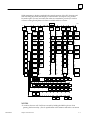

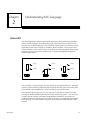
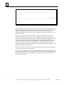
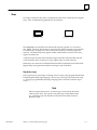

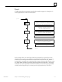
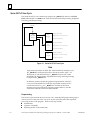
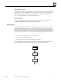
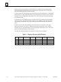
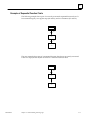

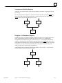

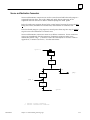
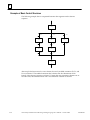
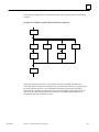
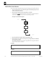
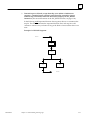
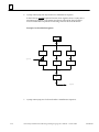
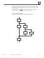
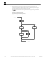
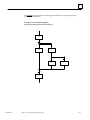
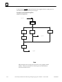

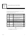
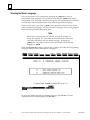
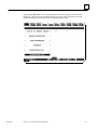
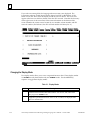
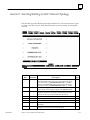
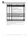
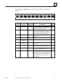

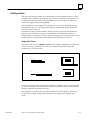
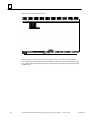
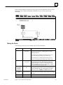
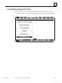
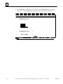
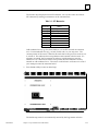
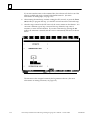

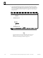
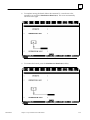
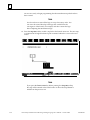
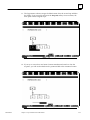
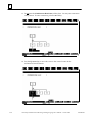
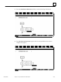

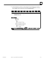
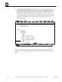
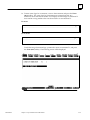
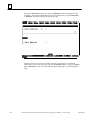
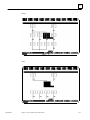
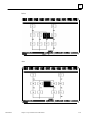

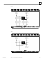

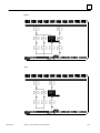
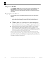
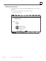
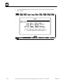
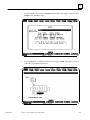


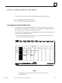
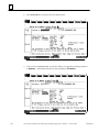
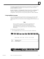
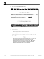
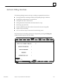


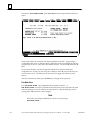

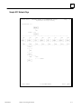

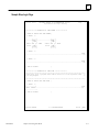
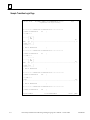

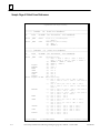
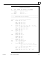
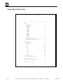


![An 8080 Simulator for the 6502, KIM-1 Version [1978]](http://vs1.manualzilla.com/store/data/005862327_1-86881d05118ae2e6f54412aa1d9ee60a-150x150.png)