1
3D Mouse
& Head Tracker
Techical Reference Manuel
3D Mouse
Head Tracker
Logitech Inc., Fremont, CA 94555
©1992 by Logitech, Inc. All Rights Reserved.
Published 1992
Printed in the United States of America
No part of this document may be copied or reproduced in any form or by any means without the
prior written consent of Logitech, Inc. (Logitech). Logitech has made every effort to ensure the
accuracy of this manual. However, Logitech makes no warranties with respect to this documentation
band disclaims any implied warranties of merchantability and fitness for a particular purpose. The
information in this document is subject to change without notice. Logitech assumes no responsibility
for any errors that may appear in this document.
Document:
Released:
620402-00 Rev B
November 1992
Trademarks
IBM PC, XT, and AT are registered trademarks of International Business Machine Corp.
Intel is a registered trademark and 80286, 80386, 286, 386, and 486 are trademarks of Intel Corp.
Logitech is a trademark of Logitech, Inc.
Microsoft, MS, and MS-DOS are registered trademarks of Microsoft Corp.
StereoGraphics and Crystal Eyes are registered trademarks of StereoGraphics Corp.
All other trademarks are the sole property of their respective manufacturers.
U.S. Government Restricted Rights
The software and associated documentation are provided with RESTRICTED RIGHTS. Use,
duplication, or disclosure by the Government is subject to restrictions as set forth in subparagraphs
(c) (1) and (I) of The Rights in Technical Data and Computer Software clause at DFARS 252.227-7013
or subparagraphs (c) (1) and (2) of the Commercial Computer Software-Restricted Rights at 48 CFR
52.227-19, as applicable. Contractor/manufacturer is Logitech Inc., 6505 Kaiser Drive, Fremont, CA
94555.
FCC Warning Statement
This equipment has been tested and found to comply with the limits for a Class A digital device,
pursuant to Part 15 of the FCC Rules. These limits are designed to provide reasonable protection
against harmful interference in a residential installation. This equipment generates, uses, and can
radiate radio frequency energy and, if not installed or used in accordance with the instructions, may
cause harmful interference to radio communications. However, there is no guarantee that
interference will not occur in a particular installation. If this equipment does cause harmful
interference to radio or television reception, which can be determined by turning the equipment off
and on, the user is encouraged to try and correct the interference by one or more of the following
measures:
• Reorient or relocate the receiving antenna.
• Increase the separation between the equipment and the receiver.
• Connect the equipment into an outlet on a circuit different from that to which the receiver is
connected.
Consult the dealer or an experienced radio/TV technician for help.
The user may find the following booklet prepared by the Federal Communications Commission
helpful: How to Identify and Resolve Radio-TV Interference Problems. This booklet,
#04-000-00345-4, is available from the U.S. Government Printing Office, Washington, D.C. 20402.
To meet FCC requirements, shielded cables and power cords are required to connect the device to
a personal computer or other Class B certified device.
ii
Information to User
Changes or modifications to this equipment not expressly approved by the party responsible for
compliance could void the user’s authority to operate the equipment.
FCC Compliance Statement
This device complies with Part 15 of the FCC Rules. Operation is subject to the following two
conditions:
1. This device may not cause harmful interference.
2. This device must accept any interference received, including interference that may cause
undesired operation.
Hardware Warranty by Fakespace, Inc.
This product is warranted to be free from defects in material and workmanship for ninety days from
the date of purchase. During this period, Fakespace will, at its sole option, replace or repair at no
charge the product which, in its opinion, is defective.
If the failed product has been modified without Fakespace’s written consent or if the failure is the
result of misuse, abuse, or misapplication, Fakespace has no obligation to repair or replace the failed
product.
Before returning a failed unit, the buyer must obtain a Return Authorization (RA) number by calling
Fakespace Product Support at (650) 688-1940. Fakespace cannot be held responsible for any
package returned without an RA number.
The buyer is responsible for packing the product properly for return shipment, and for the charges
to ship the product to Fakespace. Fakespace is responsible for charges to return the product to the
buyer.
EXCEPT AS EXPRESSLY PROVIDED ABOVE, THE HARDWARE AND ACCOMPANYING WRITTEN
MATERIALS (INCLUDING THE USER’S MANUAL) ARE PROVIDED “AS IS” WITHOUT WARRANTY
OF ANY KIND, INCLUDING THE IMPLIED WARRANTIES OF MERCHANTABILITY AND FITNESS
FOR A PARTICULAR PURPOSE, EVEN IF LOGITECH HAS BEEN ADVISED OF THAT PURPOSE. IN
NO EVENT WILL LOGITECH, INC. BE LIABLE FOR ANY DIRECT, INDIRECT, CONSEQUENTIAL, OR
INCIDENTAL DAMAGES ARISING OUT OF THE USE OF OR INABILITY TO USE SUCH PRODUCT
EVEN IF LOGITECH HAS BEEN ADVISED OF THE POSSIBILITY OF SUCH DAMAGES. SOME
STATES DO NOT ALLOW THE EXCLUSION OR LIMITATION OF LIABILITY FOR CONSEQUENTIAL
OR INCIDENTAL DAMAGES, SO THE ABOVE LIMITATION MAY NOT APPLY.
Software Public Domain Statement
The following program files have been dedicated by Logitech to the public domain: TEST3D.EXE,
SAMPLE.EXE, LOGIDRVR.C, LOGIDRVR.H, SIMPLE.C, and README.TXT. ACCORDINGLY, USE OF
THIS SOFTWARE IS AT THE SOLE RISK OF THE USER, AND LOGITECH EXPRESSLY DISCLAIMS
ANY LIABILITIES ARISING FROM THE USE OF THESE PROGRAM FILES, INCLUDING, WITHOUT
OF LIMITATION WARRANTIES OF FITNESS FOR A PARTICULAR PURPOSE AND MERCHANTABILITY,
AND NONINFRINGEMENT OF THIRD PARTY RIGHTS.
iii
iv
Table of Contents
Preface, ix
1
Introduction, 1
System Features, 1
Basic System Components, 2
Basic 3D Mouse Components, 2
Basic Head Tracker Components, 3
Additional Components and Features, 3
2
Installation and Setup, 5
Connecting the Components, 5
Arranging the Components, 7
Arranging the 3D Mouse Components, 7
Arranging the Head Tracker Components, 8
Custom Head Tracker Arrangements, 8
Running the TEST3D Program, 10
3
Component Description, 11
3D Mouse Transmitter, 11
3D Mouse Receiver, 12
Head Tracker Transmitter, 15
Head Tracker Receiver, 16
Control Unit, 16
Computer Cable, 18
Power Supply, 18
v
Table of Contents
Master/Slave Cable, 18
Audio Device (Optional), 18
4
Multiple Control Unit Components, 19
Connecting Multiple Control Units, 20
Connecting Components to Multiple Control Units, 22
5
System Operation, 23
3D Mode, 23
Coordinate System, 23
Right-Hand Rules, 24
Origin Points and Reference Axes, 26
Positional X, Y, Z Data, 27
Orientation Data, 28
Converting Euler’s Angles to Quaternions, 30
Converting Degrees to Radians, 31
Active Area, 31
Resolution, 32
Fringe Area and Out-of-Range Area, 32
Tracking Speed, 35
Reporting Modes, 35
2D Mode, 36
Active Area, 36
Resolution, 36
Tracking Speed, 36
Reporting Mode, 36
vi
Table of Contents
6
Application Programming Interface, 37
Control Unit Initialization, 37
3D Mode, 38
Mouse Data Report Format, 38
Data Format Restrictions, 40
3D Mode Commands, 40
2D Mode, 49
Reporting Data Formats, 49
2D Mode Commands, 52
7
Questions & Answers, 59
A 3D Mouse & Head Tracker Specifications, 61
B Creating a Custom Receiver, 69
Index, 71
vii
viii
Preface
This manual describes the components and operation of the 3D Mouse
and Head Tracker systems.
The information in this manual is for technical reference. It is intended
for OEMs (Original Equipment Manufacturers), VARs (Value Added
Retailers), and software and hardware developers who integrate the 3D
Mouse and Head Tracker technology into their products.
Knowledge in the following areas would be beneficial, but is not
required:
• the C programming language, and the ability to adapt the code provided
in this manual and associated software to your application-specific
programming language
• device driver development
• RS-232 (serial) communication
• 3D graphics programming
This manual is organized as follows:
Chapter 1, Introduction. This chapter introduces the 3D Mouse and
Head Tracker system features and components.
Chapter 2, Installation and Setup. This chapter describes how to install
and setup the 3D Mouse and Head Tracker components. It also describes
how to run TEST3D program.
Chapter 3, Component Description. This chapter provides a detailed
description of how each component works.
Chapter 4, Using Multiple Control Units. This chapter describes when
you need to use multiple control units, how to connect them, and which
components to connect to them.
Chapter 5, System Operation. This chapter describes how the 3D Mouse
and Head Tracker systems communicate position and orientation data to
the host computer.
ix
Table of Contents
Chapter 6, Application Programming Interface. This chapter
defines the 2D and 3D mode command set.
Chapter 7, Questions & Answers. This chapter includes commonly
asked questions about the 3D Mouse and Head Tracker systems and
recommended answers.
Appendix A, 3D Mouse & Head Tracker Specifications. This
appendix lists the 3D Mouse and Head Tracker hardware specifications.
Appendix B, Creating a Custom Receiver. This appendix provides
information to help you create a custom 3D Mouse receiver.
x
1
Introduction
This chapter summarizes the 3D Mouse and Head Tracker system
features. It also lists the basic system components, as well as additional
components you can add for more sophisticated system configurations.
System Features
The award-winning, Logitech 3D Mouse and Head Tracker allow you to
input three-dimensional, spatial information into a host computer, from
IBM PC compatibles to high-end graphics workstations. These systems
are designed for sophisticated software and hardware applications,
including CAD/CAM, computer animation, computer modeling, robotic
control, 3D graphics, and virtual reality workstations.
The 3D Mouse and Head Tracker are easy to setup and use. The
stationary transmitter emits ultrasonic signals that track the movement
of the receiver. The receiver, which you move about threedimensionally within the active area in front of the transmitter, receives
the ultrasonic signals and relays them back to the control unit. The
control unit converts the signals into position and orientation data that
can be processed by the host computer.
Configuration of the 3D Mouse and Head Tracker components is very
flexible. You can use just the 3D Mouse or the Head Tracker. You can
use both the 3D Mouse and the Head Tracker receivers at the same time.
Or, you can integrate the 3D Mouse and Head Tracker components into
your own custom system. The configuration is up to your needs.
The 3D Mouse operates in both 3D and 2D modes. The 3D mode
reports three-dimensional and rotational positions. The 2D mode
reports two dimensional positions just like an ordinary, conventional
mouse. It is 100% compatible with Logitech and Microsoft pointing
devices.
The 3D Mouse and Head Tracker allow you to incorporate voice
recognition and sound applications. The control unit provides an
Audio-Out connector for you to connect an audio processing device
and input sound through the receiver’s top microphone.
1
Chapter 1
Basic System Components
Before you install the 3D Mouse or Head Tracker, take a moment to
familiarize yourself with the associated components. The product comes
with either the 3D Mouse or Head Tracker components. For more
detailed information about how these components work, see Chapter 3,
“Component Description.”
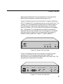
Basic 3D Mouse Components
The basic 3D Mouse system includes the components shown in
Figure 1-1.
3D Mouse
Transmitter
Power Supply
Control Unit
Computer
Cable
POW
OF
OUT GE
RAN
TRA
3D Mouse
Receiver
Figure 1-1. 3D Mouse Components
2
NSM
IT REC
EIVE
ER
Introduction
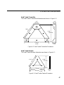
Basic Head Tracker Components
The basic Head Tracker system includes a transmitter, receiver, control
unit, power supply, and computer cable. Figure 1-2 shows the
transmitter and receiver.
Head Tracker
Transmitter
Head Tracker
Receiver
Figure 1-2. Head Tracker Transmitter and Receiver
Additional Components and Features
Multiple Control Units. You can connect up to four control units
together for simultaneous head and hand tracking (tracking with up to
four receivers and one transmitter). For more information about using
multiple control units, see Chapter 4.
Custom Devices. You can create a custom 3D Mouse receiver.
Instructions and an electrical schematic appear in Appendix B. You can
also create head tracking devices that incorporate the Head Tracker
transmitter and receiver. These components include screw holes so you
can mount them (see “Arranging the Head Tracker Components” in
Chapter 2).
Audio Processing Device Feature. You can add your own audio
processing device to the 3D Mouse system for 3D applications with
voice recognition and sound. Connect the audio processing device to
the Audio Out connector on the control unit’s rear panel. Input sound
through the 3D Mouse or Head Tracker receiver’s top microphone.
3
4
2
Installation and Setup
This chapter describes how to setup and arrange the basic 3D Mouse
and Head Tracker components. It also describes how to run the TEST3D
program so you can ensure that the components work properly.
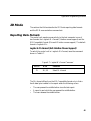
Connecting the Components
The transmitter, receiver, audio, computer, and power supply cables
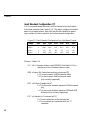
plug into the rear panel of the control unit. Figure 2-1 shows the
connectors on the control unit’s rear panel. The circled letters
correspond with the components and the order you can connect them.
ON
POWER
MASTER/SLAVE
SERIAL PORT
TRANSMITTER
AUDIO OUT
RECEIVER
D
B
C
A
OFF
E
Figure 2-1. Control Unit Back Panel Connectors
Follow these steps to connect the basic 3D Mouse or Head Tracker
components:
1. Turn off your host computer.
2. Ensure that the control unit’s On/Off switch is in the OFF
position. We recommend that you do not turn on the control unit
until you have finished connecting the components.
5
Chapter 2
3. Plug the receiver cable into the Receiver connector on the rear panel
of the control unit (see A in Figure 2-1). The arrow on the cable
should appear on top (see Figure 2-2).
Figure 2-2. Positioning the Cable Arrow
4. Plug the transmitter cable into the Transmitter connector (see B in
Figure 2-1).
5. (Optional) plug the audio cable into the Audio Out connector (see C
in Figure 2-1).
6. Plug the rounded end of the computer cable into the Serial Port
connector (see D in Figure 2-1).
7. Connect the computer cable’s 9-pin plug into an available serial
(COM) port in the back of your host computer. If your computer has
a 25-pin serial port connector, attach the 9- to 25-pin adapter
provided. Remember which serial port you use, because you will have
to indicate it when you run the TEST3D program.
8. Plug the rounded end of the power supply cable into the Power Supply
connector (see E in Figure 2-1).
9. Plug the power supply into an AC outlet or power strip.
10. Turn on your host computer.
11. Turn on the control unit. Flip the On/Off switch to the ON position.
The red Power LED on the front panel of the control unit should
light.
6
Installation and Setup
Arranging the Components
For optimum 3D Mouse and Head Tracker performance, arrange the
components as described in the following sections.
Arranging the 3D Mouse Components
Typically, arrange the 3D Mouse components as shown in Figure 1-1 in
Chapter 1. Ensure that there is sufficient cable length before connecting
the components. Place the transmitter so that it faces the 3D Mouse
receiver. Do not place any object between the transmitter and receiver.
Make sure that the plane of the 3D Mouse transmitter is parallel to the
plane of the host computer monitor.
Work in a normal office environment. Do not work near equipment that
emits loud noises or ultrasonic frequencies. Also, ensure that there are
no reflective surfaces within 12 inches of the top and sides of the
transmitter. If there is interference, relocate your system or create a
sound-absorbing barrier.
In 3D mode, ensure that there is enough space to move and rotate the
receiver in a direct line of communication with the transmitter (see
Figure 2-3)
Figure 2-3. Holding 3D Mouse in Front of the Transmitter
In 2D mode, ensure that there is enough space on your desk to move the
receiver freely in a direct line of communication with the transmitter.
7
Chapter 2
Arranging the Head Tracker Components
Arrange the Head Tracker components as discussed in the previous
section “Arranging the 3D Mouse Components.” However, when using
the Head Tracker, the transmitter does not have to be parallel with the
plane of the host computer’s monitor.
Custom Head Tracker Arrangements
The Head Tracker transmitter and receiver have screw holes so you can
mount them onto almost any custom device you design for your specific
needs. This section shows two custom devices designed by two hardware
developers that incorporate the Head Tracker components.
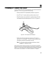
The first device, which appears in Figure 2-4, shows a head-mounted
image display designed by the Virtual Research company. The Head
Tracker receiver is mounted onto the top of the Virtual Research™
helmet. The transmitter must be mounted overhead, within range, and
in a direct line of communication with the receiver. The image on the
display adjusts to movements of the user’s head.
Figure 2-4. Head Tracker Incorporated in Head-Mounted Display
8
Installation and Setup
The second device, which appears in Figure 2-5, shows a user wearing
virtual reality, Stereographics® Crystal Eyes® VR glasses and the 3D
Mouse transmitter. These glasses, designed by the StereoGraphics®
company, function as a receiver-three microphones are imbedded in
the glasses frame.
The Crystal Eyes® VR glasses allow the user to see a virtual, holographic
image that appears to float in front of the host computer’s monitor. As
the user moves his/her head, the holographic image adjusts to the user’s
head movements.
Figure 2-5. Custom Stereographics® Glasses with Microphones
9
Chapter 2
Running the TEST3D Program
After you connect and arrange the 3D Mouse or Head Tracker
components, we recommend that you run the TEST3D Program,
provided on your program diskette. The TEST3D Program indicates
whether the components work properly.
To run the TEST3D Program, you must have an IBM PC or compatible
computer with the following:
• 386 or above
• Coprocessor
• VGA graphics adapter
• 3 ½-inch disk drive
• 2 MB (megabytes) of RAM
• DOS 5.0
Also to run the TEST3D Program, you must first view the README.TXT
information file, then follow the instructions in the “TEST3D User
Documentation” section of the file.
The README.TXT file also provides error messages that the TEST3D
program generates and suggests corrective action.
10
3
Component Description
This chapter provides a detailed reference for how the 3D Mouse and
Head Tracker components work.
3D Mouse Transmitter
The 3D Mouse transmitter includes three speakers that send 23 KHz
ultrasonic signals to the receiver (see Figure 3-1; the dark pads cover the
speakers). These ultrasonic signals track the receiver’s position and
orientation.
The 3D Mouse transmitter communicates with either the 3D Mouse or
Head Tracker receiver. The ultrasonic sound radiates from the center of
each speaker in a 100 degree spherical cone. Where these three cones
intersect is the active area of communication, see “Active Area” in
Chapter 5. There should be no obstruction within the active area.
The transmitter’s cable connects to the control unit via the Transmitter
connector. If you are using multiple control units, the transmitter
connects to the “Master” control unit only (see “Multiple Control Unit
Components” in Chapter 4).
Figure 3-1. 3D Mouse Transmitter
11
Chapter 3
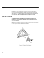
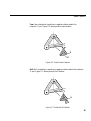
3D Mouse Receiver
The 3D Mouse receiver has a triangle of microphones at the front end
of the unit (see Figure 3-2; the three dark spots are the microphones).
These microphones sample the ultrasonic signals from the transmitter at
a rate of up to 50 times per second. The receiver relays these signals
regarding its position and orientation to the control unit.
Figure 3-2. 3D Mouse Microphones
The 3D Mouse receiver samples the transmitter’s ultrasonic signals
within the active area of communication, see “Active Area” in
Chapter 5. There should be no obstruction between the receiver and the
transmitter within this active area.
The top microphone supports audio input.
The receiver’s cable connects to the control unit via a Receiver
connector.
12
Component Description
The 3D Mouse receiver includes five, application-specific buttons: three
top buttons and two side Suspend buttons (see Figure 3-3). The top
buttons function like conventional Logitech mouse buttons-left,
middle, and right. You can use these buttons in both 2D and 3D modes.
Three top buttons
(left, middle, right)
Suspend button
(right hand)
Suspend button
(right hand)
Figure 3-3. 3D Mouse Receiver Buttons
The 3D Mouse receiver is ergonomically designed to fit comfortably in
the palm of either your right or left hand. The Suspend buttons function
identically. The left Suspend button is for right-handed user. The right
Suspend button is for left-handed users.
In 2D mode when you move the 3D Mouse on your desktop, the
Suspend buttons allow you to move the 3D Mouse without reporting its
position to the host computer. This function is the same as picking up
a conventional mouse from the desktop to reposition it without moving
the screen cursor. In 3D mode, you can assign application-specific
functions to the Suspend buttons.
13
Chapter 3
Hold the 3D Mouse receiver in a way that feels most comfortable to you.
Figures 3-4 and 3-5 show two ways of holding the mouse in 3D mode.
Figure 3-4. Holding the 3D Mouse Receiverin 3D Mode
Hold the receiver up off the desktop and move and rotate it within the
active area in front of the transmitter.
Figure 3-5. 3D Mouse Receiver Buttons
14
Component Description
In 2D mode, you can hold the 3D Mouse receiver in a way that feels
most comfortable to you. One way of the holding the mouse is
illustrated in Figure 3-6. Move the mouse around on the desktop within
the active area of the transmitter.
Figure 3-6. Holding the 3D Mouse Receiverin 2D Mode
Head Tracker Transmitter
The Head Tracker transmitter functions like the 3D Mouse transmitter
discussed earlier in this chapter (see Figure 3-7; the three large circles
are the speakers).
Figure 3-7. Head Tracker Transmitter
15
Chapter 3
However, the Head Tracker transmitter is designed so you can mount it
overhead. It includes three screw holes that allow you to mount it
securely in a direct line of communication to the receiver. See
“Arranging the Head Tracker Components” in Chapter 2.
Head Tracker Receiver
The Head Tracker receiver functions like the 3D Mouse receiver
discussed earlier in this chapter (see Figure 3-8; the three large circles
are the microphones).
Figure 3-8. Head Tracker Receiver
However, the Head Tracker receiver is designed so you can mount it to
your custom head tracking devices. Therefore, it has no buttons. Three
screw holes allow you to mount it securely onto custom devices (see
“Arranging the Head Tracker Components” in Chapter 2).
Control Unit
The control unit is the heart of the 3D Mouse and Head Tracker systems.
It contains a microprocessor, interface circuitry, and firmware that
provides the functions of the system.
Warning The control unit is fragile and cannot withstand being
dropped nor rough treatment.
The control unit decodes signals from the receiver and computes the
receiver’s position and orientation (rotation) about these coordinates
(see Chapter 5, “System Operation”). In addition, the control unit
16
Component Description
determines the status of all of the mouse buttons. It then reports this
data to the host computer via a serial communication link.
Figure 3-9 shows the control unit’s front panel. This panel includes four
LED’s. The Power LED turns red when you turn on the control unit. The
Transmit LED turns green each time the control unit sends a report to
the host computer. During high-speed transmissions, such as stream
mode, the Transmit LED turns on and off so quickly that it may appear
dim. The Receive LED turns green when the control unit receives a
command from the host computer. The Out of Range LED turns green
when you move the receiver out of the active area of transmission or
exceed the tracking speed (see Chapter 5, “System Operation”).
TRANSMIT RECEIVE
OUT OF
RANGE
POWER
Figure 3-9. Control Unit Front Panel
Figure 3-10 shows the control unit’s rear panel. This panel provides
connectors for all of the system components (see Chapter 2 for
instructions for how to connect the components to the control unit). The
rear panel also includes the On/Off switch
ON
POWER
MASTER/SLAVE
SERIAL PORT
TRANSMITTER
AUDIO OUT
RECEIVER
OFF
Figure 3-10. Control Unit Rear Panel
17
Chapter 3
Computer Cable
The 6-foot, EIA RS-232C computer cable connects the control unit to the
host computer. Its 7-pin, mini-DIN end plugs into the control unit’s rear
panel. Its 9-pin, D-sub end plugs into the computer’s serial port. (Pin
assignments for the computer cable are listed in Appendix A.) If the 9pin plug doesn’t fit your computer’s serial port, use the 9- to 25-pin
adapter.
The computer cable provides data transmission rates of 1200 bps in 2D
mode and 19,200 bps in 3D mode at full duplex, with no echo.
Power Supply
The external power supply delivers DC power to the system via the
control unit. The power supply plugs into a 115-volt wall socket or a
power strip. The barrel end of the power supply cable plugs into the
Power connector in the control unit’s rear panel. The system also
supports an optional 220V power supply.
Master/Slave Cable
The Master/Slave cable, which plugs into the control unit’s Master/Slave
connector, connects up to four control units together. One of the cable’s
four plugs is labeled “Master”; the other plugs are labeled “Slave.”
Tighten each plug’s screws to connect the Master/Slave cable securely
to each control unit connector.
Audio Device (Optional)
You can connect your own audio processing device to the control unit’s
Audio Out connector. An audio processing device allows you to
incorporate sound into 3D applications. (See Table A-1 in Appendix A
for the Audio Out pin assignments and signal names.)
Audio received by the top microphone of the receiver is amplified and
routed through the LINE_OUT pin of the Audio Out connector. The
EN_VOICE pin of the Audio Out connector is high when you press the
Suspend button and low when you release it. The EN_VOICE pin
provides support for “Push-to-Talk” applications.
18
4
Using Multiple Control Units
You can include up to four control units in a 3D Mouse and/or Head
Tracker setup. This arrangement is called “Master/Slave.”
There are several sophisticated situations when you need more than one
control unit:
• to allow one person to perform head and hand tracking at the same time
on one monitor
• to allow several people to perform head or hand tracking at the same
time
• to allow several people to work together on one project in their own
virtual space
This chapter describes the components that are necessary in a multiplecontrol unit setup, and how to connect the control units.
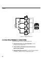
Multiple Control Unit Components
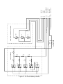
Figure 4-1 shows a block diagram of the components needed in a
Master/Slave control unit arrangement. Here, one transmitter emits
ultrasonic signals to each receiver and connects to the Master control
unit. A receiver connects to each control unit and samples the
transmitter’s ultrasonic signals. You must connect a power supply to
each control unit. Connect each control unit together in a daisy chain
using a Master/Slave cable. Finally, connect each control unit to the host
computer’s serial ports.
19
Chapter 4
AC
Master
control
unit
Master/Slave
cable
Receiver
Slave
control
unit
Transmitter
Slave
control
unit
Host
computer
Slave
control
unit
Figure 4-1. Multiple Control Unit
Connecting Multiple Control Units
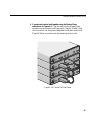
Follow these steps to connect multiple control units:
1. Stack the control units, one on top of each other. You can
include up to four control units.
2. Ensure that the On/Off switch on each control unit’s rear
panel is in the Off position.
3. Designate the Master control unit. It can be on the top or bottom
of the stack. The other control units are called “Slave.”
20
Using Multiple Control Units
4. Connect each control unit together using the Master/Slave
cable shown in Figure 4-2. Plug the cable into the Master/Slave
connector on each control unit’s rear panel. Plug the “Master” plug
into the control unit that you’ve designated the Master control unit.
Plug the “Slave” connectors into the remaining control units.
R
EIVE
REC
UT
IO O
AUD
R
ITTE
NSM
IAL
SER
T
POR
TRA
VE
/SLA
TER
MAS
R
EIVE
REC
UT
IO O
ON
AUD
ER
POW
OFF
VE
/SLA
TER
MAS
R
EIVE
REC
UT
IO O
ON
AUD
ER
POW
R
ITTE
NSM
IAL
SER
OFF
T
POR
TRA
VE
/SLA
TER
MAS
R
EIVE
REC
UT
IO O
ON
AUD
ER
POW
OFF
ON
TRA
VE
/SLA
TER
MAS
T
POR
R
ITTE
NSM
IAL
SER
ER
POW
OFF
Figure 3-10. Control Unit Rear Panel
21
Chapter 4
Connecting Components to Multiple Control Units
Follow these steps to connect components to multiple control units:
1. Connect the transmitter to the “Master” control unit only. If
you connect the transmitter to a “Slave control unit, the system will
not work. Connect the transmitter’s plug into the Transmitter
connector on the “Master” control unit’s rear panel.
2. Connect receivers to each control unit. Connect a receiver plug into
each control unit’s Receiver connector.
3. Connect a power supply cable to each control unit. Connect
the plug end of the power supply cable into each control unit’s
Power connector.
4. Connect a computer cable to each control unit. Connect the
rounded plug end of each computer cable into each control unit’s
Serial connector.
5. Turn off your host computer.
6. Connect each computer cable’s 9-pin plug into a serial (COM)
port in the back of the host computer. If your computer has a
25-pin serial port connector, attach the 9- to 25-pin adapters
provided. Remember which serial ports you use, because you will
have to indicate them when you run the TEST3D program (for IBM
PCs only).
7. Turn on your host computer.
8. Turn on each control unit. Flip each On/Off switch to the ON
position. The red Power LED on the front panels of each control unit
should light.
22
5
System Operation
The 3D Mouse and Head Tracker systems operate as follows: the
transmitter emits ultrasonic signals. The control unit, via the receiver,
detects these signals and derives receiver position and orientation data.
The control unit reports this data and 3D Mouse button activity to the
host computer.
This chapter describes the following:
• position and orientation data
• the active area of operation of the 3D Mouse and Head Tracker
systems in both 2D and 3D modes
• the reporting modes the control unit provides in both 2D and 3D
3D Mode
In 3D mode, you can move the 3D Mouse or Head Tracker receiver
three-dimensionally along three axes-X, Y, Z-and rotate it about
these axes. The control unit derives the receiver’s position and
orientation and reports this data to the host computer.
Coordinate System
In 3D mode, the 3D Mouse and Head Tracker systems use a rectangular,
Cartesian coordinate system to report the relationship between the
receiver and the transmitter-the receiver’s position and orientation.
23
Chapter 5
Figure 5-1 shows the positive, three-dimensional direction of receiver
movement-the X, Y, and Z axes. It also shows the positive rotation about
these axes. Negative movement is in the direction opposite each arrow.
0 Degrees
Yaw Rotation
Y
Origin
Z
X
0 Degrees
Pitch Rotation
0 Degrees
Roll Rotation
Figure 5-1. Three-Dimensional Axes and Rotation
Right-Hand Rules
The 3D Mouse and Head Tracker systems use two right-hand rules to
help you determine position and orientation. The first right-hand rule
allows you to hold your thumb, index finger, and middle finger of the
right hand at right angles to each other to indicate the positive direction
of the X, Y, and Z axes (see Figure 5-2).
24
System Operation
Y
Z
X
Figure 5-3. Right-Hand Rule Showing the X, Y, Z Axis
The second right-hand rule allows you to point your thumb in the
positive direction of any axis and to curl your four fingers to represent
positive rotation about that axis. In Figure 5-3, the thumb is pointed
along the positive X axis, and the four fingers curl in the direction of
positive rotation about that axis.
Positive direction
of rotation about
the X axis
Figure 5-3. Right-Hand Rule Showing Rotation About the X Axis
25
Chapter 5
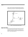
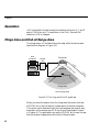
Origin Points and Reference Axes
The positional and orientation data generated by the control unit are
based on the 3D origin points and reference axes. In Figure 5-4, the
transmitter’s origin point and reference axes are defined by the
following:
• XT is an imaginary reference axis that passes through the center of
the transmitter’s lower left speaker and through the center of the
transmitter’s lower right speaker. (Only the positive direction of this
is shown in Figure 5-4.)
• YT is an imaginary reference axis passing through the center of the
transmitter’s top speaker and is perpendicular to XT.
• ZT is an imaginary reference axis perpendicular to both XT and YT.
• The transmitter’s origin is the point where XT, YT, and ZT intersect.
Also in Figure 5-4, the receiver’s origin point and reference axes are
defined by the following:
• XR is an imaginary reference axis passing through the center of the
receiver’s lower left microphone and through the center of the
receiver’s lower right microphone. (Only the positive direction of
this axis is shown in Figure 5-4.)
• YR is an imaginary reference axis passing through the center of the
receiver’s top microphone and is perpendicular to XR.
• ZR is an imaginary reference axis perpendicular to both XR and YR.
• The receiver’s origin is the point where XR, YR, and ZR intersect.
Note
26
The transmitter’s and receiver’s origin points and reference axes
described above also apply to the 3D Mouse transmitter and
receiver.
System Operation
YT
Transmitter
XT
Origin
YR
ZT
Receiver
XR
Origin
ZR
Figure 5-4. Transmitter and Receiver Origin Points and Reference Axes
Positional X, Y, Z Data
Positional data is the distance between the transmitter’s and receiver’s
origin points.
X Data. This is the distance the receiver’s origin point is to the left or
right (along the XT axis) of the transmitter’s origin point (see Figure 5-4).
Y Data. This is the distance the receiver’s origin point is above or below
(along the YT axis) the transmitter’s origin point-minus a 12-inch offset
(see Figure 5-4). When the receiver is sitting on the desktop level with
the base of the transmitter, the Y data will be approximately a negative
12 inches.
27
Chapter 5
Z Data. This is the distance the receiver’s origin point is away (along
the ZT axis) from the transmitter’s origin point-minus an 18-inch offset
(see Figure 5-4). When the receiver is 6 inches away from the transmitter
the Z axis, the Z data will be approximately a negative 12 inches.
Orientation Data
Orientation describes the rotation of the receiver with respect to the
transmitter. The orientation is described using the aeronautical terms:
Pitch, Yaw, and Roll.
Pitch. Pitch orientation is positive or negative rotation about the receiver’s
X axis. Figure 5-5 shows positive Pitch rotation.
Y
X
Z
Figure 5-5. Positive Pitch Rotation
28
System Operation
Yaw. Yaw orientation is positive or negative rotation about the
receiver’s Y axis. Figure 5-6 shows positive Yaw rotation.
Y
X
Z
Figure 5-6. Positive Yaw Rotation
Roll. Roll orientation is positive or negative rotation about the receiver’s
Z axis. Figure 5-7 shows positive Roll rotation.
Y
X
Z
Figure 5-7. Positive Roll Rotation
29
Chapter 5
Orientation data is represented in Y-X-Z Euler’s angles. For example, the
orientation of 0 degrees Pitch, 0 degrees Yaw, and 0 degrees Roll is
reported when both of the following conditions are met:
• The receiver’s reference axis ZR is parallel to the transmitter’s
reference axis ZT (see Figure 5-4).
• The receiver’s microphones are facing towards the transmitter’s
speakers.
To position the receiver at a particular orientation (for example, Yaw =
30 degrees, Pitch = 40 degrees, and Roll = 50 degrees) from an initial
starting orientation of zero degrees for Yaw, Pitch, and Roll, you must
perform these steps in the order presented:
1.
Yaw the receiver 30 degrees.
2.
Pitch the receiver 40 degrees.
3.
Roll the receiver 50 degrees.
Converting Euler’s Angles to Quaternions
The Quaternions coordinate system is another way of representing
orientation. This system uses four coordinates to specify orientation in
a smoother, more natural way. (For more information about using
Quaternions to specify rotation in space, see the Siggraph 1985 paper:
“Animating Rotation with Quaternion Curves” by Ken Shoemake, San
Francisco, July 22-26.)
If you prefer to use Quaternions to define orientation instead of Euler’s
angles, the following formulas will help you convert from Euler’s angles.
w = cos (R/2) • cos (P/2) • cos (Y/2) + sin (R/2) • sin (P/2) • sin (Y/2)
x = cos (R/2) • sin (P/2) • cos (Y/2) + sin (R/2) • cos (P/2) • sin (Y/2)
y = cos (R/2) • cos (P/2) • sin (Y/2) + sin (R/2) • sin (P/2) • cos (Y/2)
z = sin (R/2) • cos (P/2) • cos (Y/2) + cos (R/2) • sin (P/2) • sin (Y/2)
30
System Operation
Converting Degrees to Radians
Radians are a unit of angular measure for rotation. If you prefer to use
radians instead of degrees, the following formulas will help you convert
from degrees. To convert degrees to radians, use the following
formulas:
P = P • π/180
Y = Y • π/180
R = R • π/180
Active Area
From each transmitter speaker, ultrasonic sound disperses in a spherical,
100-degree cone. These three cones of sound overlap in a dispersion
pattern shown in Figure 5-8. Where these cones overlap is the active
area of communication. The active area extends 5 feet from each
transmitter speaker. The receiver should be within this area.
100°
Active area
Figure 5-8. The Active Area
31
Chapter 5
Resolution
In 3D mode within the active area, the resolution along the X, Y, and Z
axes is 1/250 of an inch. The resolution in the Pitch, Yaw, and Roll
rotations is 1/10 of a degree.
Fringe Area and Out-of-Range Area
The fringe area is a 1-foot band along the edge, within the active area
(see the block diagram in Figure 5-9).
Host
computer
Transmitter
Control
unit
e
ng
a
f-r
4
Ou
a
e
ar
100°
f-r
et
an
-o
ut
ge
ar
ea
O
ea
e
tiv
fe
t-o
ar
1
fo
ot
Receiver
Ac
ti
ve
ar
ea
Ac
Fringe area
Out-of-range area
Figure 5-9. The Fringe and Out-of-Range Areas
When you move the receiver into this fringe area, the control unit sets
a FRINGE bit in the first byte of its data report to the host computer.
(The control unit’s data report tells the host computer the position and
orientation of the receiver, see 3D Mode, Mouse Data Report Format”
in Chapter 6.) The application can use the FRINGE bit to warn the user
that the receiver is approaching the limits of the active area.
32
System Operation
When the receiver is out of range, the control unit sets an OUT bit in
the first byte of its data report to the host computer. This data report
contains the last valid report when the receiver was in range. This last
valid report allows the application to use the returned data report.
If the receiver is out of range when the control unit returns the first data
report, the control unit sets the OUT bit and the positional and
orientation data contains all zeros. This allows the application to notify
the user to move the receiver into range.
Also, if the receiver’s tracking speed exceeds 30 inches per second, the
control unit sets the OUT bit.
Note
The FRINGE bit and the OUT bit are mutually exclusive;
therefore, the control unit never sets both bits simultaneously.
The FRINGE Bit
The FRINGE bit is located at Bit 6 in the first byte of the 3D mode
mouse data report (see Table 6-2 in Chapter 6).
The OUT Bit
The OUT bit is located at Bit 5 in the first byte of the 3D mode mouse
data report (see Table 6-2 in Chapter 6). This bit signifies three out-ofrange conditions:
• when you move the receiver out of the out-of-range area
• when the receiver is not in a direct line of communication with the
transmitter
• when you move the receiver faster than the maximum tracking speed
33
Chapter 5
OUT Bit Set-First Report. The OUT bit in the first byte of the data
report is as follows (if the receiver is not in range, and has never been
in range since you powered on or initialized the control unit, when the
report is requested):
1x1xxxxx*
00000000
byte 1
byte 2 through byte 16
*The letter “x” means “don’t care,” could be 0 or 1.
This “all-zero” data report is repeated until you move the receiver in
range, because the control unit always returns the last valid position and
orientation in 3D mode. In this case, there has been no previously valid
information.
OUT Bit Example
If your application converts absolute information into relative
information, prompt the user to move the receiver into range before
completing the control unit’s initialization. This approach avoids a large
relative change in position/orientation from the all-zero data report to
the first valid data report. The following is a C pseudo-code example:
// go get the data report
get_report (report);
// first report valid?
if (report [0] & logitech_OUTBIT) {
// first report invalid, request user to move the
receiver printf (“Please move the Logitech receiver in
range.\n”);
// stick around until I get a valid data report
do {
// go get another report
get_report (report);
} while (report [0] & logitech_OUTBIT);
//cheers to the user
printf (“Logitech receiver detected.\n”);
}
// squirrel away the report for later processing
save_report (report);
34
System Operation
OUT Bit Set-Out of Range or Obscured. After the first data report,
the unit always has a last-valid data report. Therefore when the receiver
moves out of range or the ultrasonic path is obstructed, the position and
orientation data reflects the last valid data report.
For applications that convert absolute information to relative changes,
the data report can usually be used as is. In effect, the sensor is not
tracked until it is brought back into range.
For applications using absolute information directly, old valid
information is typically not acceptable to use. So, the OUT bit notifies
the user, via the application, that the point is invalid.
Note
All the mouse buttons will operate regardless of the status of the
OUT bit. In other words, the mouse does not need to be in range
for button toggling.
Tracking Speed
In 3D mode, the receiver accurately tracks up to 30 inches per second
(ips). If the speed exceeds 30 ips, the control unit sets the OUT bit.
Reporting Modes
In 3D mode, the control unit reports to the host computer in three
modes: demand, incremental, and stream. Demand reporting mode is
default.
Demand Reporting Mode. In this mode, the control unit sends a
single report only when requested by the host computer.
Incremental Reporting Mode. In this mode, the control unit reports
automatically each time the receiver changes position or orientation.
Stream Reporting Mode. In this mode, the control unit reports at the
maximum rate regardless of the receiver movement.
37
Chapter 5
2D Mode
In 2D mode, you can move the 3D Mouse on a flat surface (the desktop
or table). It behaves like a conventional 2- or 3-button mouse. The
control unit reports button activity and two-dimensional movement to
the host computer.
Using the Suspend buttons or picking the mouse up from the desk
suppresses mouse reports. These actions enable you to reposition the
mouse without moving the screen object.
Active Area
In 2D mode, the active area is the same as in 3D mode; however, it is
limited to a ½-inch space above the base of the transmitter on the Y axis.
For example, if you raise the 3D Mouse over a ½ inch above the base of
the transmitter, the receiver is out of range.
Resolution
In 2D mode, the resolution is 400 dpi within the active area. The
resolution can be reduced at the driver level to support any resolution
up to 400 dpi.
Tracking Speed
In 2D Mode, the 3D Mouse tracking speed is also 30 inches per second.
Reporting Mode
In 2D Mode, the control unit reports in Incremental report mode only.
The maximum reporting rate is 44 reports per second.
36
6
Application Programming Interface
This chapter describes how to initialize the control unit. It also describes
the 2D and 3D mode command set.
Examples of how to use the 3D Mode command set are included in the
3D Mouse driver source code provided on the program disk.
Control Unit Initialization
This section describes how to initialize or reset the control unit and the
subsequent effects on the control unit.
You can initialize the control unit in any one of three ways:
a.
Turn on the control unit.
b.
Send the *R (Software Reset) command to the control unit from the
host computer (see the Software Reset command in the “3D Mode
Commands” section later in this chapter).
c.
Perform an RTS line toggle on the RS-232 interface. The RTS toggle
occurs when the RTS line is negative for at least 100 ms, and then
becomes positive. (See restrictions below.)
Procedures a. and b. cause the control unit to enter 3D Mode
initialization. The three green LEDs on the control unit’s front panel
toggle on and off. 3D Mode initialization sets the serial port to 19,200
bps: 8 data bits, no parity, and 1 stop bit. No characters are sent back to
the host computer.
After 3D Mode initialization, the driver should wait at least 1 second and
perform an *<enq> (Diagnostics) command to ensure that the control
unit is functioning properly. For more information about the Diagnostics
command, see the “3D Mode Commands” section later in this chapter.
Procedure c. causes the control unit to enter 2D Mode initialization. 2D
Mode initialization sets the serial port to 1200 bps: 7 data bits, no parity,
and 1 stop bit. The end of the initialization sends the following twocharacter status message back to the host computer (see Table 6-1).
37
Chapter 6
Figure 6-1. 2D Mode End Status Message
ASCII
M,3
HEX
4D,33
Function
3 button device declaration
This status message tells the host computer that the initialization routine
has been completed and the control unit is in 2D Mode.
Upon power on, reset, or RTS toggle, the 3D Mouse sends back one or
two characters specifying the type of device-M3. The driver must
determine what type of device is connected. This is performed by
sending the *? (Send Standard Configuration) command. The device
should respond within 100 ms.
3D Mode
The sections that follow describe the 3D Mouse data report format, the
data format restrictions, and the 3D Mode command set.
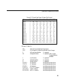
Mouse Data Report Format
The control unit reports 3D Mode activity to the host computer, such as
position, orientation, and button activity via the mouse data report. The
size of the mouse data report is 16 bytes (see Table 6-2).
38
Application Programming Interface
Figure 6-2. Mouse Data Report Sixteen-Byte Format
Name
Byte 1
Byte 2
Byte 3
Byte 4
Byte 5
Byte 6
Byte 7
Byte 8
Byte 9
Byte 10
Byte 11
Byte 12
Byte 13
Byte 14
Byte 15
Byte 16
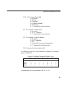
Bit7 Bit6 Bit5 Bit4 Bit3 Bit2 Bit1 Bit0
1
0
0
0
0
0
0
0
0
0
0
0
0
0
0
0
FRI OUT
P
S
X20
X19
X18
X17
X13
X12
X11
X10
X6
X5
X4
X3
Y20
Y19
Y18
Y17
Y13
Y12
Y11
Y10
Y6
Y5
Y4
Y3
Z20
Z19
Z18
Z17
Z13
Z12
Z11
Z10
Z6
Z5
Z4
Z3
PI13 PI12 PI11 PI10
PI6
PI5
PI4
PI3
YA13 YA12 YA11 YA10
YA6
YA5
YA4
YA3
RO13 RO12 RO11 RO10
RO6 RO5 RO4 RO3
L
X16
X9
X2
Y16
Y9
Y2
Z16
Z9
Z2
PI9
PI2
YA9
YA2
RO9
RO2
M
X15
X8
X1
Y15
Y8
Y1
Z15
Z8
Z1
PI8
PI1
YA8
YA1
RO8
RO1
R
X14
X7
X0
Y14
Y7
Y0
Z14
Z7
Z0
PI7
PI0
YA7
YA0
RO7
RO0
Where in Table 6-2,
FRI
OUT
P
0S
= Mouse has entered the fringe space.
= This report is invalid-the mouse is out of range.
= Mouse stand button
1 = pressed
= Suspend button
1 = pressed (left or right
Suspend button
pressed)
L
= Left button
1 = pressed
M
= Middle button
1 = pressed
R
= Right button
1 = pressed
X20-X0
= X distance
see following restrictions
Y20-Y0
= Y distance
see following restrictions
Z20-Z0
= Z distance
see following restrictions
PI13-PI0
= PITCH rotation
see following restrictions
YA13-YA0 = YAW rotation
see following restrictions
RO13-RO0 = ROLL rotation
see following restrictions
39
Chapter 6
Data Format Restrictions
This section describes the restrictions that are associated with the X, Y,
Z, Pitch, Yaw, and Roll values in Table 6-2.
•
X, Y, and Z fields correspond to signed numbers with absolute
maximum values of -1048576 and +1048575 (or 221). Each bit in the
X, Y, and Z fields represent a dot with a resolution of 1/1000 inch.
Therefore, the maximum spatial range is approximately ±1048
inches or ±87 feet from the origin of each axis.
•
Pitch, Yaw, and Roll fields correspond to unsigned binary numbers
with absolute maximum values of 16383. Each bit in these fields
represent one part, with a resolution of 40 parts per degree. The
maximum rotational range is 360 degrees, and the maximum
number of parts required to cover the entire rotational range is
14400 (0-14399).
The 3D Mouse rotation is measured in 10 parts per degree.
Therefore, the lower two bits of the Pitch, Yaw, and Roll fields are
always 0.
•
In 3D mode, mouse data reports are 16 bytes in length, with 10 bits
transmitted per byte (1 start bit, 8 data bits, and 1 stop bit). The
software generates reports at a maximum rate of 50 reports per
second.
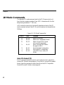
3D Mode Commands
This section describes the standard 3D Mode command set. The
standard 3D mode command sent to the 3D Mouse control unit from the
host computer consists of two or more characters with the first always
being an asterisk “*” (2A hex). You must issue all 3D mode commands
except the Software Reset (*R) command and the Demand Reporting
(*D) command) while the system is in the Demand reporting mode. You
can issue the exceptions in any 3D reporting mode.
40
Application Programming Interface
In 3D mode, the control unit ignores all characters not part of the 3D
mode command set (see Table 6-3) and all characters not transmitted at
19,200 bps.
Figure 6-3. 3D Mode Commands
ASCII
HEX
*<
*R
*D
*d
*I
*S
*<enq>
*A
*O
*m
*$…
*$…
*$…
2A, 3C
2A, 52
2A, 44
2A, 64
2A, 49
2A, 53
2A, 05
2A, 41
2A, 4F
2A, 6D
2A, 24
2A, 24
2A, 24
Function
Invoke 2D Mode
Software Reset
Demand Reporting
Demand a Single Report
Incremental Reporting
Stream Reporting
Diagnostics
Enable Transmitter Output
Disable Transmitter Output
Current Operating Information
Set Slave Transmitter
Set Filter Count
Set Custom Receiver Dimensions
Invoke 2D Mode (*<)
The *< switches the control unit from 3D to 2D Mode. The serial port is
set to 1200 bps: 7 data bits, no parity, and 1 stop bit.
Software Reset (*R)
The *R command resets the control unit. You can issue this command in
any 3D reporting mode.
Wait at least 1 second after the software reset command before sending
any other commands. This allows the initialization process to complete.
41
Chapter 6
Demand Reporting (*D)
The *D command switches the control unit to the Demand reporting
mode. In this mode, the control unit stops generating mouse data
reports automatically and only generates a mouse data report upon
request via a *d (Demand a Single Report) command. You can issue the
*D command in any 3D reporting mode. If you issue this command
while the control unit is transmitting a report, the report will continue
to the end and will not be truncated.
Demand a Single Report (*d)
The *d command causes the control unit to transmit the last valid 3D
[mouse data report. If the receiver or transmitter are not operating, or if
the receiver is not in a valid tracking space, the points returned from
successive single report commands will not change. Position and
orientation data for the receiver is updated every 20 ms within the
control unit. Therefore, the mouse data report received in Demand
reporting mode can be delayed up to 20 ms from when the control unit
has updated the position and orientation data for the receiver. You can
only issue this command in Demand Reporting mode.
Incremental Reporting (*I)
The *I command switches the control unit to the Incremental reporting
mode. In this reporting mode, the control unit sends mouse data reports
continuously as long as the receiver is moving. The host computer may
have to keep up with an information flow of up to 50 reports per second.
42
Application Programming Interface
Stream Reporting (*S)
The *S command causes the control unit to enter the Stream reporting
mode. In Stream reporting mode, the control unit sends mouse data
reports continuously. The host computer may have to keep up with an
information flow of 50 reports per second.
Diagnostics (*<enq>)
The *<enq> command causes the control unit to return a two-byte
response containing diagnostic information (see Table 6-4).
Figure 6-4. Diagnostic Response
Name
Byte 1
Byte 2
Bit7 Bit6 Bit5 Bit4 Bit3 Bit2 Bit1 Bit0
1
0
0
0
T5
TB
T4
TA
T3
T9
T2
T8
T1
T7
T0
T6
Where in Table 6-4,
TO
T1
T2
T3
T4
T5
T6
T7
T8
T9
TA
TB
= Control Unit test
= Processor test
= EPROM checksum test
= RAM test
= Transmitter test
= Receiver test
= Serial Port test
= EEPROM test
= Reserved
= Reserved
= Reserved
= Reserved
In the above test results, a “0” indicates that the test failed. A “1”
indicates that the test passed. Therefore, a BF 3F (hex) represents an “All
Pass” result. Any other response indicates that at least one test failed.
43
Chapter 6
Enable Transmitter Output (*A)
The *A command enables the speaker output from the transmitter (see
Table 6-5). Speaker output enabled is the default.
Disable Transmitter Output (*0)
The *O command disables the speaker output from the transmitter (see
Table 6-5).
Figure 6-5. Enable/Disable Transmitter Output Commands
ASCII
HEX
Function
*A
*O
2A, 41
2A, 4F
Enable Transmitter Output
Disable Transmitter Output
Current Operating Information (*m)
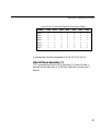
The *m command causes the control unit to return a 30-byte current
operating information report (see Table 6-6).
Figure 6-6. Current Operating Information Command Format
44
Name
Bit 7
Bit 6
Bit 5
Bit 4
Bit 3
Bit 2
Bit 1
Bit 0
Byte 1
1
0
V5
V4
V3
V2
V1
V0
Byte 2
0
D6
D5
D4
D3
D2
D1
D0
Byte 3
0
RM6
RM5
RM4
RM3
RM2
RM1
RM0
Byte 4
0
RD6
RD5
RD4
RD3
RD2
RD1
RD0
Byte 5
0
RS6
RS5
RS4
RS3
RS2
RS1
RS0
Byte 6
0
T6
T5
T4
T3
T2
T1
T0
Application Programming Interface
Figure 6-6. Current Operating Information Command Format
Name
Bit 7
Bit 6
Bit 5
Bit 4
Bit 3
Bit 2
Bit 1
Bit 0
Byte 7
0
MS6
MS5
MS4
MS3
MS2
MS1
MS0
Byte 8
0
A6
A5
A4
A3
A2
A1
A0
Byte 9
0
RCV6 RCV5 RCV4 RCV3 RCV2 RCV1 RCV0
Byte 10
0
XMT6 XMT5 XMT4 XMT3 XMT2 XMT1 XMT0
Byte 11
LRR7
LRR1
LRR0
Byte 12
LRR15 LRR14 LRR13 LRR12 LRR11 LRR10 LRR9
LRR8
Byte 13
LTR7
LTR1
LTR0
Byte 14
LTR15 LTR14 LTR13 LTR12 LTR11 LTR10 LTR9
LTR8
LRR6
LTR6
LRR5
LTR5
LRR4
LTR4
LRR3
LTR3
LRR2
LTR2
Byte 15
RES
RES
RES
RES
RES
RES
RES
BD0
Byte 16
LRX7
LRX6
LRX5
LRX4
LRX3
LRX2
LRX1
LRX0
Byte 17
LRX15 LRX14 LRX13 LRX12 LRX11 LRX10 LRX9
LRX8
Byte 18
LTX7
LTX1
LTX0
Byte 19
LTX15 LTX14 LTX13 LTX12 LTX11 LTX10 LTX9
LTX8
Byte 20
LCX7
LCX1
LCX0
Byte 21
LCX15 LCX14 LCX13 LCX12 LCX11 LCX10 LCX9
LCX8
Byte 22-30
RES
LTX6
LCX6
RES
LTX5
LCX5
RES
LTX4
LCX4
RES
LTX3
LCX3
RES
LTX2
LCX2
RES
RES
RES
Where in Table 6-6,
V5…V0 = Firmware Version Index (same as in 2D command, *?)
1 = Firmware Version 1.0
2 = Firmware Version 2.0
3 = Reserved
4 = Firmware Version 1.1
5 = Reserved
45
Chapter 6
Where in Table 6-6 (continued),
D6…D0 = Dimension
D0 = 2D mode
D1 = 3D mode
RM6…RM0 = Reporting Mode
RM0 = Incremental Reporting
RM1 = Demand Reporting
RM2 = Stream Reporting
RD6…RD0 = Reporting Data Type
RD0 = Euler Data Type (Default)
RS6…RS0 = Reporting Data Record Size (in number of bytes)
T6…T0 = Tracking Mode
T0 = Mouse Tracking (Default)
MS6…MS0 = Master/Slave Status
MS0 = Slave
MS1 = Master
A6…A0 = Audio Level
Value = 0 (Audio Off )
Value = 1 (Audio On)
RCV6…RCV0 = Receiver Type Connected
Value = 15 (No Receiver Connected)
Value = 14 (Mouse Receiver)
Value = 13 (Head Tracker Receiver)
Value = 12 (Mouse Receiver with Pedestal)
Value = 11 (Crystal Eyes VR Receiver)
Value = 10 through 2 (Reserved)
Value = 1 (Custom Receiver)
Value = 0 (Reserved)
46
Application Programming Interface
Where in Table 6-6 (continued),
XMT6…XMT0 = Transmitter Type Connected
Value = 15 (No Transmitter Connected)
Value = 14 (Mouse Transmitter Frame)
Value = 13 (Head Tracker Transmitter Frame)
Value = 12 through 0 (Reserved)
LRR15…LRR0 = Distance from receiver’s lower left microphone to
lower right microphone (.001 inch units)
LTR15…LTR0 = Distance from receiver’s lower microphone to top
microphone (.001 inch units)
BD0 = Button Disabled Status
Value = 1 (Buttons Disabled on Receiver)
Value = 0 (Buttons Enabled on Receiver)
LRX15…LRX0 = Distance from transmitter’s lower speaker to lower
right speaker (.001 inch units)
LTX15…LTX0 = Distance from transmitter’s lower left speaker to
top speaker (.001 inch units)
LCX15…LCX0 = Distance from transmitter’s lower left speaker to
calibration microphone (.001 inch units)
RES = Reserved for future extensions [0]
Set Slave Transmitter Type
This command sets the Slave control unit’s transmitter type. The
command structure is in a hex, 5-byte format as follows:
Byte 1 2A
Byte 2 24
Byte 3 02
Byte 4 01
Byte 5 Slave’s transmitter type
The transmitter-type byte is generally derived from sending the *m
(Current Operating Information) command to the Master control unit,
and getting the Master control unit’s transmitter type. The Master control
unit’s transmitter type is also the Slave control unit’s transmitter type.
47
Chapter 6
Set Filter Count
Inside the firmware is a filtering system that reduces data jitter (a slight
fluctuation in the position and orientation data when the receiver is
stationary). Increasing the filter count reduces the amount of jitter, but
increases the system latency (the length of time that elapses between
when the receiver moves and when the control unit reports the
receiver’s movement). Each additional filter count above 1 increases the
latency an additional 20 ms. Permissible filter count values are 1 to 10.
The default is 1. The command structure is in a hex, 5-byte format as
follows:
Byte 1 2A
Byte 2 24
Byte 3 02
Byte 4 07
Byte 5 Filter count
Set Custom Receiver Dimensions
If you create your own custom receiver, send the Set Custom Receiver
Dimensions command to the control unit, and notify the control unit of
the dimensions of the custom receiver. The command structure is in a
hex, 10-byte format as follows:
Byte 1
2A
Byte 2
24
Byte 3
07
Byte 4
08
Byte 5
01
Bytes 6 & 7 The distance from the Lower Left Microphone to the
Lower Right Microphone is calculated in .001 inch units
(2 Bytes Low Byte, High Byte order).
Bytes 8 & 9 The distance from the Lower Left Microphone to the
Top Microphone is .001 inch units (2 Bytes Low Byte,
High Byte order).
Byte 10
The Button Disabled status is stored in one byte and is
as follows:
1 = Buttons Disabled on Receiver
0 = Buttons Enabled on Receiver
48
Application Programming Interface
2D Mode
The sections that follow describe the 2D Mode reporting data formats
and the 2D Mouse emulation command set.
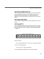
Reporting Data Formats
The control unit reports mouse activity to the host computer in one of
two formats: the Logitech M+ Format (3-button mouse support) and the
MS-Compatible Format (Microsoft 2-button mouse support). The default
format is Logitech M+.
Logitech M+ Format (Full 3-Button Mouse Support)
To switch the control unit to Logitech M+ Format, issue the command
shown in Table 6-7.
Figure 6-7. Logitech M+ Format Command
ASCII
HEX
Function
*X
2A, 58
Select M+ format
The M+ format differs from the MS-Compatible format only in that a
fourth data byte is added to the report when the following occurs:
•
•
•
The user presses the middle button since the last report.
A report is sent while the user presses the middle button.
The user releases the middle button.
49
Chapter 6
The four-byte M+ format is shown in Table 6-8.
Figure 6-8. M+ Mouse Report Format
•
Name
Bit6
Bit5
Bit4
Bit3
Bit2
Bit1
Bit0
Byte 1
Byte 2
Byte 3
Byte 4
1
0
0
0
L
X5
Y5
M
R
X4
Y4
DT4
Y7
X3
Y3
DT3
Y6
X2
Y2
DT2
X7
X1
Y1
DT1
X6
X0
Y0
DT0
The fourth byte is transmitted only when one of the middle button
conditions is met.
Where in Table 6-8,
L = Left Button,
R = Right Button,
M = Middle Button,
“1” = pressed
“1” = pressed
“1” = pressed
X7...X0 = X movement since the last report is expressed as an 8
bit two’s complement value (-128 to +127); positive
East.
Y7...Y0 = Y movement since the last report is expressed as an 8bit two’s complement value (-128 to +127); positive
South.
DT4...DT0 = Device type; 5 bits interpreted as follows:
0 = Unknown
1 = Mouse
2 = Trackman(tm)
3 = Trackman Portable(tm)
4 = 3D Mouse
5...31 = Reserved for future use
In M+ format, data is transmitted in the form of seven-bit bytes. There
is one stop bit and no parity bit. Each report consists of three or four
bytes (depending on whether the middle button conditions are met).
50
Application Programming Interface
The X and Y movements are relative to the X and Y positions last
reported. The X movement is positive to the East and negative to the
West; Y movement is positive to the South and negative to the North.
MS-Compatible Format (Microsoft 2-Button Mouse Support)
To switch the control unit to Logitech MS-Compatible Format, issue the
command shown in Table 6-9.
Figure 6-9. Logitech MS-Compatible Format Command
ASCII
HEX
Function
*V
2A, 56
Select MS-Compatible format
In MS-Compatible format, each mouse report sent to the host computer
consists of three bytes, each byte containing seven bits. The three bytes
contain the status of each of the two buttons and the relative X and Y
movements of the mouse. The format of the three bytes is shown in
Table 6-10.
Figure 6-10. MS-Compatable Mouse Report Format
Name
Bit6
Bit5
Bit4
Bit3
Bit2
Bit1
Bit0
Byte 1
Byte 2
Byte 3
1
0
0
L
X5
Y5
R
X4
Y4
Y7
X3
Y3
Y6
X2
Y2
X7
X1
Y1
X6
X0
Y0
Where in Table 6-10,
L = Left Button,
R = Right Button,
“1” = pressed
“1” = pressed
X7...X0 = X movement since the last report is expressed as an 8-bit
two’s complement value (-128 to +127); positive East.
Y7...Y0 = Y movement since the last report is expressed as an 8-bit
two’s complement value (-128 to +127); positive South.
51
Chapter 6
2D Mode Commands
The standard 2D mode command sent to the 3D Mouse control unit
from the host computer consists of two ASCII characters with the first
always being an asterisk: “*” (2A hex).
In 2D mode, the control unit ignores all characters not part of the 2D
mode command set (see Table 6-11) and all characters not transmitted at
1200 bps.
Figure 6-11. 2D Mode Command Set
ASCII
HEX
Function
*X
*V
*U
2A, 58
2A, 56
2A, 55
*c
2A, 63
*?
*!
*>
2A, 3F
2A, 21
2A, 3E
Select M+ Format
Select MS-Compatible Format
Select 5-Byte (MSC) Mode
(not currently supported)
Send Copyright and Version
Number in ASCII
Send Standard Configuration
Send Specific Configuration
Leave 2D Mode, Invoke 3D
Mode
Select M+ Format (*X)
The *X command causes the control unit to switch to the Logitech M+
Format (full 3-button mouse support). Since the M+ format is the default
format, issue this command to switch back from the MS-Compatible
Format (Microsoft 2-button mouse support).
52
Application Programming Interface
Select MS-Compatible Format (*V)
The *V command causes the 3D Mouse to switch to a 100% compatible
Microsoft 2-button mouse format. Also, it allows the 3D Mouse to
support a third button transparently. The middle mouse button is
supported by simultaneously pressing or releasing both the left and right
buttons.
Select 5-Byte (MSC) Format
This command is not supported in the current implementation of the 3D
Mouse.
Send Copyright (*c)
The *c command causes the control unit to transmit an ASCII string of
up to 127 characters to the host computer. The string contains copyright
information about the control unit firmware, and is formatted as shown
in Table 6-12.
Figure 6-12. Send Copyright String
Name
Bit6
Bit5
Bit4
Bit3
Bit2
Bit1
Bit0
Byte n
A6
A5
A4
A3
A2
A1
A0
Where in Table 6-7,
A6..A0 = Represents the ASCII code of the nth character transmitted
The ASCII string transmitted is
<CR><LF>JA 1.0 © 1991 Logitech<NUL>
The transmitted string is updated in each new firmware release.
53
Chapter 6
Send Standard Configuration (*?)
The *? command causes the control unit to transmit a four-byte report
to the host computer (see Figure 6-13). This report contains information
about the firmware version, report bit rate, bit rate capabilities, device
type, number of buttons, protocol, and current mouse configuration.
Figure 6-13. Send Standard Configuration Four-Byte Report Format
Name
Bit6
Bit5
Bit4
Bit3
Bit2
Bit1
Bit0
Byte 1
Byte 2
Byte 3
Byte 4
1
0
0
0
V5
RBR
B2
RES
V4
BRC
B1
RES
V3
EXT
B0
RES
V2
DT2
P2
RES
V1
DT1
P1
RES
V0
DT0
P0
RES
Where in Table 6-13,
V5…V0 = Firmware Version Index [000001] (See Table 6-6 for a
description of the Firmware Version Index)
RBR = Report Bit Rate before receiving a command [0]
0 = The device was in 1200 bit/second mode.
1 = The device was in 9600 bit/second mode.
[not currently supported]
BRC = Bit Rate Capabilities [0]
0 = The device can transmit reports at 1200 bit/second
only.
1 = The device can transmit reports at 1200 and 9600
bit/second [not currently supported]
EXT = Extension to Command set [1]
0 = There is extension to the command set
1 = The command set is extended with the “*!”
command.
54
Application Programming Interface
DT2…DT0 = Device Type [100]
0 = Unknown
1 = Mouse
2 = Trackman™
3 = Trackman Portable™
4 = 3D Mouse
5…7 = Reserved for future extensions
B2…B0 = Number of buttons [011]
0 = Unknown
1…4 = 1…4 buttons
5…7 = Reserved for future extensions
P2…P0 = Protocol in use [010; default]
0 = Unknown
1 = MS-Compatible
2 = M+
3 = 5 Byte MSC (not currently supported)
4…7 = Reserved for future extensions
RES = Reserved for future extensions [0]
The default string for the *? (Send Standard Configuration) command is
shown in Table 6-14.
Figure 6-14. Standard Configuration Default String
Name
Bit6
Bit5
Bit4
Bit3
Bit2
Bit1
Bit0
Byte 1
Byte 2
Byte 3
Byte 4
1
0
0
0
0
0
0
0
0
0
1
0
0
1
1
0
0
1
0
0
0
0
1
0
1
0
0
0
In hexadecimal, this string translates to 41, 0C, 1A, 00.
55
Chapter 6
Send Specific Configuration (*!)
The *! command relays device-specific information to the host
computer. This command causes the control unit to send a seven-byte
message containing information about the 3D Mouse’s configuration
(see Table 6-15).
Note:
Currently, the majority of space in the Send Specific
Configuration report is reserved for future extensions.
Figure 6-15. Specific Configuration Information
Name
Bit6
Bit5
Bit4
Bit3
Bit2
Bit1
Bit0
Byte 1
Byte 2
Byte 3
Byte 4
Byte 5
Byte 6
Byte 7
1
0
0
0
0
0
0
T5
RES
RES
RES
RES
RES
RES
T4
RES
RES
RES
RES
RES
RES
T3
RES
RES
RES
RES
RES
RES
T2
RES
RES
RES
RES
RES
RES
T1
RES
RES
RES
RES
RES
RES
T0
RES
RES
RES
RES
RES
RES
Where in Table 6-15,
T5…T0 = Type of device extension [000010]
0 = Unknown
1 = Wireless Device
2 = 3D Mouse
3 = Reserved
RES = Reserved for future extensions [0]
The current-release report that is transmitted to the host computer is
shown in Table 6-16.
56
Application Programming Interface
Figure 6-16. Current Send Specific Configuration Report
Name
Bit6
Bit5
Bit4
Bit3
Bit2
Bit1
Bit0
Byte 1
Byte 2
Byte 3
Byte 4
Byte 5
Byte 6
Byte 7
1
0
0
0
0
0
0
0
0
0
0
0
0
0
0
0
0
0
0
0
0
0
0
0
0
0
0
0
0
0
0
0
0
0
0
1
0
0
0
0
0
0
0
0
0
0
0
0
0
In hexadecimal, this string translates to 42, 00, 00, 00, 00, 00, 00.
Enter 3D Mouse Emulation (*>)
The * command switches the 3D Mouse from 2D Mode to Mode. It
also switches the serial port to 19,200 bps: 8 data bits, no parity, and 1
stop bit.
57
58
7
Questions & Answers
This chapter describes how you can solve problems that may occur
while you’re using the 3D Mouse and Head Tracker systems.
What should I do if an error appears when I run the TEST3D
program?
If an error message appears on the screen when you run the TEST3D
program, it means that a component failure has possibly occurred. Try the
following troubleshooting procedures:
• See “Diagnostics <*enq>” in Chapter 6.
• Reboot your system through drive A.
• Ensure that all component cables are connected properly.
• Check communication (COM) ports and interrupt settings.
• Listen closely to the transmitter and ensure that there is a humming
sound.
• Ensure that the red LED indicator on the control unit’s front panel
is on.
• Run the TEST3D program (see Chapter 2).
• Setup the 3D Mouse or Head Tracker system on another computer.
What should I do if the Red LED on the control unit won’t light?
If the red LED indicator on the front panel fails to light, perform each of
the following checks until the problem is resolved:
• Check that the power supply is plugged into an AC outlet and
connected to the control unit.
• Check that the control unit is turned on.
• Check that AC power is available at the AC outlet.
59
Chapter 7
Can I connect a Head Tracker and 3D Mouse receiver to
one computer and track them both?
Yes. You can use two receivers at the same time with two control units.
To connect multiple control units, see “Connecting Multiple Control
Units” in Chapter 4.
I’ve connected multiple control units properly using the
Master/Slave cable. Why won’t the transmitter work?
Even though you’ve connected the control units properly, you may have
connected the transmitter to the wrong control unit. Ensure that you’ve
connected the transmitter to the “Master” control unit. If you’ve
connected the transmitter to a “Slave” control unit, it won’t work.
What is the 3D Mouse and Head Tracker operating range?
The active area is a 100-degree, spherical cone that extends from the
transmitter for 5 feet, see “Active Area” and “Fringe Area and Out-ofRange Area” in Chapter 5.
Can I setup two transmitters in the same room?
Yes, as long as the transmitters are not facing each other. To avoid
interference, we recommend that you position each transmitter facing in
the same direction and allow a 10-foot separation.
60
A
3D Mouse & Head Tracker Specifications
This appendix defines the 3D Mouse and Head Tracker system
specifications.
3D Mouse Components
3D Mouse Transmitter
3D Mouse Receiver
Control Unit
Power Supply
Computer Cable
Head Tracker Components
Head Tracker Transmitter
Head Tracker Receiver
Control Unit
Power Supply
Computer Cable
TEST3D Program Minimum System Requirements
IBM PC or compatible computer with the following:
386 or above
Coprocessor
VGA graphics adapter
3 ½-inch floppy drive
2 MB (megabytes) of RAM
DOS 5.0
Operating Modes
Dimensional Modes
2D Mode
3D Mode
Reporting Modes
Demand Reporting (3D Mode Default)
Incremental Reporting (2D Mode Default)
Stream Reporting
Reporting Formats
2D Mode (M+ and MS)
3D Mouse (Mouse Data Report)
61
Chapter A
2D Mode Pointing Device Compatibility
3-button Logitech
2-button Microsoft
Tracking Speed
Up to 30 inches per second (ips)
Tracking Area
5-foot-long, 100-degree cone
Resolution
Position. 2D Mode (400 dpi); 3D Mode (1/250 inch)
Orientation. 2D Mode (not applicable); 3D Mode (1/10 degree)
Ultrasonic Sound Frequency
23 kilohertz (kHz)
Latency
30 milliseconds (ms)
Reporting Rate
Demand Reporting: up to 50 reports per second
Incremental Reporting: up to 50 reports per second
Stream Reporting: 50 reports per second only
Accuracy
The accuracy is 2% of the distance between the transmitter and the
receiver.
Operating Temperature
5 to 35 degrees Centigrade
62
3D Mouse & Head Tracker Specifications
Operating Relative Humidity
10 to 90% non-condensing
Reliability
Electrical MTBF: 20,000 hours
Control Unit Connectors
Power supply: 2-pin male
Master/Slave: 15-pin high-density, D-sub
Transmitter: 9-pin, mini-DIN, female
Receiver: 8-pin, mini-DIN, female
Audio Out: 5-pin, mini-DIN, female
Serial port: 7-pin, mini-DIN, female
Audio Output
Amplitude: 1 Vp-p, 600 Ohm load
Band Width: 15 Hz to 5 kHz
Audio Input
The top microphone on the 3D Mouse and Head Tracker receivers
supports audio input.
Pin Assignments
Audio Out
To support the Audio-Out feature, the control unit is equipped with a 5pin, mini-DIN socket (see Figure A-1) with pin assignments shown in
Table A-1.
5
4
2
3
1
Figure A-1. Audio-Out Connector
63
Chapter A
Table A-1. Audio Out Pin Assignments
Pin No.
Signal Name
1
2
3
4
5
GND
LINE_OUT
Reserved
EN_VOICE
Shield GND
Signal Type
Analog Output
TTL Output
Serial Port
Table A-2 shows the control unit’s Serial Port connector pin
assignments.
Table A-2. Serial Port Connector Pin Assignments
64
Pin No.
Signal Name
Signal Type
1
2
3
4
5
6
7
CTS
RXD
TXD
DTR
GND
DSR
RTS
Input
Input
Output
Output
Input
Output
3D Mouse & Head Tracker Specifications
Table A-3 shows the pin assignments for the computer cable’s 9-pin, DSub, serial port connector.
Table A-3. 9-Pin, D-Sub Serial Port Pin Assignments
Note
Pin No.
Signal Name
Signal Type
1
2
3
4
5
6
7
8
9
Not Connected
RXD
TXD
DTR
GND
DSR
RTS
CTS
Not Connected
Input
Output
Output
Input
Output
Input
All serial port inputs and outputs are EIA RS-232C compatible.
Also, all signal names and signal types are from the point of view
of the host.
Table A-4 shows the pin assignments for the 9- to 25-pin adapter.
Table A-4. 9- to 25 Pin, Adapter Pin Assignments
9-Pin
25-Pin
Data Signals
Shell
3
2
7
8
6
5
4
1
2
3
4
5
6
7
20
Protective GND
Receive Data (To Mouse)
Transmit Data (From Mouse)
Request to Send
Clear to Send
Data Set Ready
Signal GND
Data Terminal Supply
65
Chapter A
AC Power
Supplied Power Supply
115 volts AC; 60 Hz
Optional Power Supply
220 volts AC; 50 Hz
Component Cable Lengths
Transmitter: 6 feet
Receiver: 9.5 feet
Power Supply: 6 feet
Computer Cable: 6 feet
Master/Slave: 2 feet
Physical Dimensions
Control Unit
Depth: 9 1/2 inches (240 mm)
Height: 1 5/8 inches (41 mm)
Width: 7 1/4 inches (185 mm)
3D Mouse Transmitter
Depth: 3 5/8 inches (93 mm)
Height: 7 3/4 inches (196 mm)
Width: 11 inches (280 mm)
3D Mouse Receiver
Depth: 5 7/8 inches (149 mm)
Height: 2 7/8 inches (72 mm)
Width: 4 3/8 inches (110 mm)
66
3D Mouse & Head Tracker Specifications
Head Tracker Transmitter
The Head Tracker Transmitter dimensions are shown in Figure A-2.
2.0"
1 1/4"
50 mm
30 mm
3m
m
7 5/8"
19
7 5/8"
194 mm
275 mm
40 mm
10 5/8"
1 5/8"
Figure A-2. Head Tracker Transmitter Dimensions
2 5/8"
70
m
2 3/4"
m
Head Tracker Receiver
The Head Tracker Receiver dimensions are shown in Figure A-3.
67 mm
74 mm
2 7/8"
83 mm 3 1/4"
8 mm
3/8"
Figure A-3. Head Tracker Receiver Dimensions
67
68
B
Creating a Custom Receiver
You can create a custom 3D Mouse receiver for your work environment or
application. To do so, we recommend the following:
• See the provided 3D Mouse assembly schematic (Figure B-2).
• Use a 332 ohm ID resistor value to provide a receiver value 1.
• Shape the receiver as an equilateral or isosceles triangle, with the
one unequal side as the base (see points R1 to R2 in Figure B-1).
R3
R2
R1
R4
Figure B-1. 3D Mouse Points of Reference
• Position each of the microphones a minimum of 5 inches to a
maximum of 10 inches apart. The wider the spacing between each
microphone, the better the orientation accuracy.
Note For information about purchasing microphones, contact
Fakespace Inc. (see rear of cover).
When using a custom receiver, the control unit must know the receiver’s
dimensions. After you connect the receiver to the control unit and turn the
power on, you must send the Set Custom Receiver Dimensions command
to the control unit, see section “3D Mode Commands” in Chapter 6.
69
Figure B-2. 3D Mouse Assembly Schematic
SW5 SUSPEND
SW4 SUSPEND
SW3 RIGHT
SW2 MIDDLE
SW1 LEFT
R8
50K
R6
50K
R4
50K
R7
25K
R5
25K
R3
25K
R2
50K
SWITCH NETWORK
R1
50K
ID RESISTOR
R100
332 Ω
2
1
2
1
2
1
TOP
LEFT
RIGHT
SHIELD
NO CONNECTION
RECEIVER MICROPHONE ASSEMBLY
SHIELD GROUND
ID RESISTOR
P3-SHELL
P3-5
SWITCH NETWORK
P3-4
SHIELD GROUND
GROUND
P3-6
+5 VOLT SUPPLY
TOP MIC
P3-3
P3-8
LEFT MIC
P3-2
P3-7
RIGHT MIC
P3-1
Index
Numerics
2D mode
active area 36
command set 52
emulation commands 52
initialization 37
pointing device compatibility 62
reporting data formats 49
Logitech M+ 49
MS-Compatible 51
reporting mode 36
resolution 36
tracking speed 36
2D mode command set
Enter 3D Mouse Emulation (*) 57
Select 5-byte (MSC) Format (*U) 53
Select M+ Format (*X) 52
Select MS-Compatible Format (*V) 53
Send Copyright (*c) 53
Send Specific Configuration (*!) 56
Send Standard Configuration (*?) 54
3D mode
axes illustrated 24
command set 40
coordinate system 23
data format restrictions 40
initialization 37
mouse data report format 38
orientation data 28
reporting modes 35
resolution 32
right-hand rules 24
rotations illustrated 24
tracking speed 35
X,Y,Z positional data 27
3D mode command set
Current Operating Information (*m) 44
Demand a Single Report (*d) 42
Demand Reporting (*D) 42
Diagnostics (*<enq>) 43
Disable Transmitter Output (*O) 44
Enable Transmitter Output (*A) 44
Incremental Reporting (*I) 42
Invoke 2D Mode (*<) 41
Set Custom Receiver Dimensions 48
Set Filter Count 48
Set Slave Transmitter Type 47
Software Reset (*R) 41
Stream Reporting (*S) 43
3D Mouse
arranging components 7
assembly schematic 73
basic components 2, 61
basic components illustrated 2
components, arranging 7
how to create a custom receiver 73
positional reference points, illustrated 27
receiver 12
buttons 13
buttons illustrated 13
custom 3
dimensions 66
holding in 2D mode 15
illustrated 15
holding in 3D mode 14
illustrated 14
microphones illustrated 12
transmitter 11
dimensions 66
illustrated 11
3D Mouse and Head Tracker
additional components 3
connecting components 5
installation and setup 5
specifications 61
71
Index
(Numerics continued)
system features 1
system operation 23
troubleshooting 59
9- to 25-pin serial port pin assignments 65
9-pin serial port pin assignments 65
A
Accuracy 62
Active area 31
illustrated 31, 32
Audio device 18
Audio Out
connector pin assignments 63
device pin assignments 64
specification 63
Audio processing device 3
C
Component cable
lengths 66
positioning the arrow 6
Components
arranging 3D Mouse 7
arranging Head Tracker 7
connecting to control unit 5
Computer Cable, RS-232C 18
Connecting components
audio device 6
computer cable 6
power supply 6
receiver 6
transmitter 6
Connecting computer cable to serial port 6, 22
Control unit 16
connectors 17, 63
dimensions 66
front panel 17
initialization 37
Master 19, 20
Master/Slave cable 19, 21
multiple 3, 19
rear panel 17
rear panel illustrated 5
reset 37
Slave 20
turning on 6
Current Operating Information (*m) command 44
Custom 3D Mouse receiver 3, 69
D
Degrees, converting to radians 31
Demand a Single Report (*d) command 42
Demand Reporting (*D) command 42
Demand reporting mode 35
Diagnostics (*<enq) command 37, 43
Dimensional mode
2D 61
3D 61
Disable Transmitter Output (*O) command 44
E
Enable Transmitter Output (*A) command 44
Enter 3D Mouse Emulation (*) command 57
Euler’s angles, converting to Quaternions 30
F
Formulas
converting degrees to radians 31
converting Euler’s angles to Quaternions 30
72
Index
Fringe area 32
illustrated 32
Fringe bit 33
H
Head Tracker
arranging components 8
basic components 3, 61
custom arrangements 8
receiver 16
dimensions 67
illustrated 3, 16
transmitter 15
dimensions 67
illustrated 3, 15
I
Incremental Reporting (*I) command 42
Incremental reporting mode 35
Invoke 2D Mode (*<) command 41
L
Latency 48, 62
Logitech M+ Format 49
M
Master/Slave
cable 18
illustrated 21
control units illustrated 20
MS-Compatible Format 51
Multiple control units 3
components illustrated 20
connecting 20, 22
illustrated 21
Master/Slave cable illustrated 21
necessary components 19
why necessary to use 19
O
Operating Relative Humidity 63
Operating Temperature 62
OUT bit 33
data report 34
example code 34
Out-of-range area 32
illustrated 32
P
Pitch rotation 28
defined 28
illustrated 24, 28
Point of origin illustrated 24
Power supply 18
specifications 66
Q
Questions & Answers 59
R
README.TXT information file 10
Receiver
how to position in an orientation 30
origin point 26
illustrated 27
reference axes 26
illustrated 27
tracking speed 35
73
Index
Receiver microphones, where to purchase 73
Receiver ultrasonic sampling rate 12
Reliability 63
Reporting mode 7
demand 35
incremental 35
stream 35
Reporting rates 62
Resolution 32, 62
Right-hand rule
to determine rotation about an axis 25
illustrated 25
to determine X,Y,Z axes 25
Roll rotation
defined 29
illustrated 24, 29
RTS line toggle 37
T
S
X
Select 5-Byte (MSC) Format (*U) command 53
Select M+ Format command (*X) 52
Select MS Compatible Format (*V) command
Send Copyright (*c) command 53
Send Specific Configuration (*!) command 56
Send Standard Configuration (*?) command 54
Serial port connector pin assignments 64
Set Custom Receiver Dimensions command 48
Set Filter Count command 48
Set Slave Transmitter Type command 47
Software Reset (*R) command 37, 41
Stream Reporting (*S) command 43
Stream reporting mode 35
Suspend buttons 13
X axis 24
X positional data 27
X,Y,Z axes illustrated 24
74
TEST3D program
computer requirements 10, 61
error messages 10
how to run 10
Tracking speed 35, 62
Transmitter
origin point 26
illustrated 27
reference axes 26
illustrated 27
Transmitter ultrasonic frequency range 11, 62
Troubleshooting (see Questions & Answers)
U
Ultrasonic sound frequency 62
Y
Y axis 24
Y positional data 27
Yaw rotation
defined 29
illustrated 24
Z
Z axis 24
Z positional data 28
Index
75
LOGITECH™
3D MOUSE &
HEAD TRACKER
TECHNICAL REFERENCE MANUAL
Corporate Headquarters:
Logitech, Inc.
Fremont, CA 94555
This product assembled in U.S.A. by:
Fakespace Inc.
(650) 688-1940
241 Polaris Avenue
Mountain View, CA 94043
620402-00
REV C