1
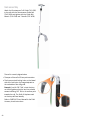
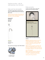
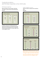
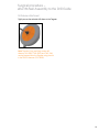
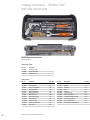
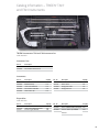
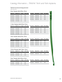
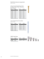
Surgical Technique Including TRIGEN™ TAN™ and FAN Trochanteric and Femoral Antegrade Intramedullary Nails Surgical Technique Table of contents Indications..................................................................................................2 TRIGEN TAN and FAN case examples........................................................4 Design features: TAN...................................................................................5 Implant specifications: TAN.........................................................................6 Design features: FAN...................................................................................7 Implant specifications: FAN.........................................................................8 Surgical Technique....................................................................................9 Patient positioning.......................................................................................9 Incision and entry point...............................................................................14 Entry portal acquisition ...............................................................................15 Alternative technique: Entry portal..............................................................16 Fracture reduction........................................................................................18 Reducer removal..........................................................................................18 Implant measurement..................................................................................19 Preparing the canal......................................................................................19 Unreamed technique...................................................................................20 Nail assembly...............................................................................................22 Nail insertion................................................................................................26 Check nail depth..........................................................................................27 Nail anteversion...........................................................................................28 Proximal locking.........................................................................................35 Standard femoral locking...........................................................................35 Recon locking.............................................................................................36 Distal locking..............................................................................................38 Nail cap insertion: Optional.......................................................................38 Implant removal.........................................................................................40 Guide rod jamming technique...................................................................41 Catalog information.................................................................................42 Nota Bene The technique description herein is made available to the healthcare professional to illustrate the authors’ suggested treatment for the uncomplicated procedure. In the final analysis, the preferred treatment is that which addresses the needs of the patient. 1 Indications The TRIGEN™ TAN™ and FAN intramedullary nails are indicated for fractures of the femur, including intertrochanteric, basi/transcervical femoral neck fractures and subtrochanteric fractures, ipsilateral femoral neck/shaft fractures, stable and unstable shaft fractures, segmental fractures, nonunions and malunions, polytrauma, reconstructions following tumor resection and bone lengthening and shortening. 2 TRIGEN™ SURESHOT™ indications Legend Important warnings appear in orange Tips, tricks and important information appear in blue Indications, contraindications, intended use and training The Smith & Nephew TRIGEN SURESHOT Distal Targeting System is intended to be an intraoperative image-guided localization system. It is a computer-assisted orthopaedic surgery tool to aid the surgeon with drill positioning for screws during intramedullary nail implantation. It provides information to the surgeon that is used to place surgical instruments during surgery utilizing intraoperatively obtained electromagnetic tracking data. The Smith & Nephew TRIGEN SURESHOT Targeting System is indicated for long bone fractures treated with intramedullary nails in which the use of stereotactic surgery may be appropriate. An example of a surgical procedure includes but is not limited to locating and drilling the distal holes in an intramedullary nail. Contraindications The screw targeting software application for this system is contraindicated for all IM nails other than Smith & Nephew TRIGEN META-NAIL™, TAN™, FAN, Humeral, Pediatric and Adolescent nails. Do not operate the TRIGEN SURESHOT Targeter within 200mm of an installed pacemaker. The magnetic field produced by the Targeter may interfere with the operation of the pacemaker. Intended use The TRIGEN SURESHOT Distal Targeting System is only designed for use with the indicated implants and instruments. Implants and instruments must be used in accordance with the instructions, as described in this manual and/or in the non-navigated surgical procedure. Training Only trained operators are allowed to use the TRIGEN SURESHOT Distal Targeting System. The various operating instructions must be fully read and understood as part of the training. If any part of the instructions is unclear, please contact your local representative. Plausibility check As with all technical equipment, malfunctions may occur due to improper use or, more rarely, technical failure. To reduce the risks involved with such technical malfunction the operation can be completed using manually controlled instruments, providing the malfunction is detected without delay. It is, therefore, important to check the plausibility of the steps, as indicated by the system, and to carry out verification of the software targeting, particularly when using the system for the first time. Should there be any doubt regarding correct functioning, the targeting should be verified or a switch made to a traditional X-Ray technique. Refer to the SURESHOT User Manual (7118-1540) for details about the SURESHOT Distal Targeting System. 3 TRIGEN™ TAN™ and FAN Nail case examples Case 1 Preoperative Postoperative Case 2 Preoperative 4 Postoperative Design features: TAN™ 130° Femoral and 130°/ 135° Recon screw angles 12° of built-in femoral neck anteversion for optimal proximal screw position Hybrid proximal-distal AP Bow transition: 1.5m-2.5m Unique five-hole proximal locking configuration allows femoral or recon locking modes in one nail 5° lateral offset for minimally invasive trochanteric entry Color coded: Lime = left Rose = right Cannulated, round geometry for ease of insertion using reamed or unreamed technique Static and dynamic distal locking configuration using 5.0mm TRIGEN™ Internal Hex Captured Locking Screws 5 TRIGEN™ Trochanteric Antegrade Nail (TAN™) specifications From bone shaft centerline Standard Femoral Lock 130º/135º TAN 130° or 135°* *From bone shaft centerline Recon Lock (12° Anteversion) 130º/135º TAN 10, 11.5 & 13mm 130º/135º TAN – Distal Lock (M-L view) Specifications TRIGEN TAN Nail Material TI6AL4V Diameter 10, 11.5 & 13mm Lengths 30-50cm Nail Color - Left Lime Nail Color - Right Rose Cross Section Round Neck Angle 130º/135º Proximal Diameter (driving end) 13mm Distal Diameter (non-driving end) 10, 11.5 & 13mm (diameter of the nail) Smallest Thru Diameter 5.4mm Wall Thickness 2.3mm (10 diameter) 3.0mm (11.5 diameter) 2.3mm (13 diameter) Guide Bolt Thread 5/16-24 Alternative Guide Bolts (Removal only) RT Tibial, Retrograde, IMSC, Revision Alternative Modes Standard Femoral Recon Locking Proximal Locking Screw Diameter Standard - 5.0mm Recon - 6.4mm Major Diameter Standard - 5.0mm Recon - 6.4mm Minor Diameter Standard - 4.3mm Recon - 4.7mm Shank N/A Recon - 6.3mm Hex Size 4.7mm Alternative Hexdrivers RT Femoral & Recon, 7.0mm Cannulated Screw, PERI-LOC™ Locking Screw Guide Screw Color Standard Lock - Gold Recon Lock - Blue Screw Lengths Standard - 25-110mm Recon - 65-125mm Anteversion Recon Lock - 12º Location 21, 33 & 47mm Proximal Dynamization Slot No Proximal Screw Hole Dimensions Standard - 5.3mm Recon - 6.4mm Degree of Proximal Bend 5º lateral Location of Proximal Bend 65mm (AP bend) Distal Locking Proper Screw Measurement All TRIGEN locking screw measuring devices, measure from bottom of head to the last complete thread of screw. This is the working length of the screw. Thus, the screw itself is longer than the measurement and adding length is not necessary. Note These views are not to scale and should be used as a pictorial representation only. 6 Screw Diameter 5.0mm Major Diameter 5.0mm Minor Diameter (core) 4.3mm Screw Color Gold Screw Lengths 25-110mm Location 15, 20 & 40mm Orientation L-M Dynamization Slot Yes Distal Screw Hole Dimensions 5.3mm AP Bow Proximal - 1.5 meters Distal - 2.5 meters Location of Distal Bend 100mm Dynamization Slot Location Distal Design features: FAN 130° Femoral and Recon screw angles 12° of built-in femoral neck anteversion for optimal proximal screw position Hybrid proximal-distal AP Bow transition: 1.5m-2.5m Unique five-hole proximal locking configuration allows femoral or recon locking modes in one nail Straight proximal profile for ease of insertion through the piriformis fossa Color coded: Lime = left Rose = right Cannulated, round geometry for ease of insertion using reamed or unreamed technique Static and dynamic distal locking configuration using 5.0mm TRIGEN™ Internal Hex Captured Locking Screws 7 TRIGEN™ Femoral Antegrade Nail (FAN) specifications * *From bone shaft centerline Standard Femoral Lock (130º standard FAN/Exchange) Specifications TRIGEN FAN Nail Material TI6AL4V Diameter 10, 11.5, 13, 14.5 & 16mm Lengths 30-50cm, 36-44cm Nail Color - Left Lime Nail Color - Right Rose Cross Section Round Neck Angle 130º Proximal Diameter (driving end) 13mm (10, 11.5 & 13 diameter) 14.5mm (14.5 diameter) 16mm (16 diameter) Distal Diameter (non-driving end) 10, 11.5, 13, 14.5 & 16mm (diameter of the nail) Smallest Thru Diameter 5.4mm Wall Thickness 2.3mm (10 diameter) 3.0mm (11.5 diameter) 2.3mm (13 diameter) 2.3mm (14.5 diameter) 2.4mm (16 diameter) Guide Bolt Thread 5/16-24 Alternative Guide Bolts (Removal only) RT Tibial, Retrograde, IMSC, Revision Alternative Modes Standard Femoral Recon Locking Proximal Locking Recon Lock (12°Anteversion, 130º standard FAN/Exchange) Distal Lock (130º standard FAN/ Exchange) Proper Screw Measurement All TRIGEN locking screw measuring devices, measure from bottom of head to the last complete thread of screw. This is the working length of the screw. Thus, the screw itself is longer than the measurement and adding length is not necessary. Note These views are not to scale and should be used as a pictorial representation only. 8 Screw Diameter Standard - 5.0mm Recon - 6.4mm Major Diameter Standard - 5.0mm Recon - 6.4mm Minor Diameter Standard - 4.3mm Recon - 4.7mm Shank Standard - N/A Recon - 6.3mm Hex Size 4.7mm Alternative Hexdrivers RT Femoral & Recon, 7.0mm Cannulated Screw, PERI-LOC™ Locking Screw Guide Screw Color Standard Lock - Gold Recon Lock - Blue Screw Lengths Standard - 25-110mm Recon - 65-125mm Anteversion Recon Lock - 12 Degrees Location 21, 33 & 47mm Proximal Dynamization Slot No Proximal Screw Hole Dimensions Standard - 5.3mm Recon - 6.4mm Degree of Proximal Bend N/A Location of Proximal Bend N/A Distal Locking Screw Diameter 5.0mm Major Diameter 5.0mm Minor Diameter (core) 4.3mm Screw Color Gold Screw Lengths 25-110mm Location 15, 20 & 40mm Orientation L-M Dynamization Slot Yes Distal Screw Hole Dimensions 5.3mm AP Bow Hybrid Bow Proximal 1.5 meters Distal 2.5 meters Location of Distal Bend 100mm Dynamization Slot Location Distal Surgical Technique Patient positioning Place the patient in the supine or lateral decubitus position on a fracture table. The foot of the affected limb is placed in a foot holder or a pin is inserted through the calcaneus for traction purposes. The unaffected limb is extended below and away from the affected limb or flexed and placed in a leg holder. Check the affected limb for length and rotation by comparison to the unaffected limb. Abduct the torso 10°-15° to allow clear access to the intramedullary canal. Rotate the C-Arm to ensure optimal AP and lateral visualization of the entire femur. Note If using a radiolucent table, a distraction device may be helpful in reducing the fracture. 9 Warnings and cautions for TRIGEN™ SURESHOT™ Refer to the SURESHOT User Manual (7118-1540) for all warnings, cautions, maintenance, cleaning and sterilization instructions. Devices for system set up TRIGEN™ SURESHOT™ Targeter Cat. No. 7169-2801 Trauma Interface Cat. No. 7169-2802 Power Cord Cat. No. 6680-0193 Note The Targeter will be operated within the sterile field and may have contact with the skin of the patient. The drill sleeve inserts will be used in the incision and have direct bone contact. Note Verify that the Targeter housing is not damaged (holes, tears, cracks). If the housing or the connector is damaged, the Targeter is no longer safe to use. Note If the Targeter is not recognized after connection to the system, the Targeter is defective and must be exchanged. (See also instrument connection). Note Broken or damaged instruments must be exchanged immediately and sent back to Smith & Nephew, Inc. Note This device is provided non-sterile and must be cleaned and sterilized per Cleaning and Sterilization (Smith & Nephew document 7138-1339) prior to use. Note Verify version 2.0.2 or higher is installed before using Sureshot with TAN/FAN Nails. To find the software version select: MENU > About 10 WARNING: The maximum temperature of the Targeter body can reach 47° Celsius at ambient room temperatures above 30° C. The Targeter body should not remain in constant contact with a patient’s exposed skin for more than one minute. Surgical procedure – OR preparation Trauma Interface setup After the sterile areas have been established, place the Trauma Interface (7169-2802) in the desired non-sterile location and turn on the power switch. CAUTION: No other electrical devices should be placed near the Trauma Interface. See the “Guidance and Manufacturer’s Declaration – Separation Distances” table at the end of this document. Note If the Trauma Interface does not power on, make sure the switch is in the “on” position. Note The means for mains disconnection of power to the Trauma Interface is the appliance inlet located below the power switch. The Trauma Interface should not be positioned such that it is difficult to reach this location. TRIGEN™ SURESHOT™ Targeter connection When the display prompts for tool connections, connect the TRIGEN SURESHOT Targeter (7169-2801) to the Targeter port on the Trauma Interface. 11 Surgical procedure – OR preparation The SURESHOT Targeter will change color to orange upon successful connection to the Trauma Interface. CAUTION: The Targeter body may have contact with the patient and must remain in the sterile field at all times. Only the cable and connector may be removed from the sterile field. CAUTION: Connect the Targeter at least 10 minutes prior to targeting in order to ensure proper accuracy. Note When oriented as shown, the connector should assemble easily. Do not force the connector into the port. Note If the Targeter is properly connected to the system and the application remains in this screen for more than 30 seconds, the Targeter may have been damaged during cleaning/sterilization. In this case another Targeter has to be used. Note It is possible at any time to disconnect and reconnect tools when the application is running. The display will show a screen reporting the missing instrument. 12 Instruments for opening the proximal femur 3.2mm x 343mm Brad Point Drill Tip Threaded Guide Pin Cat. No. 7167-4130 Honeycomb Cat. No. 7167-4075 Entry Portal Tube Cat. No. 7167-4060 12.5mm Entry Reamer Cat. No. 7167-4076 Entry Portal Handle Cat. No. 7167-4092 14mm Channel Reamer Cat. No. 7163-1039 Cat. No. 7163-1116 T-handle Mini Connector Cat. No. 7163-1186 3.2mm T-handle Trocar Cat. No. 7167-4074 Cannulated Awl Cat. No. 7167-4000 13 Incision and entry point* Assemble the Honeycomb (7167-4075), Entry Portal Handle (7167-4092) and Entry Portal Tube (7167-4060). The pieces will lock in place securely at either 0° or 180°. A longitudinal incision is made proximal to the greater trochanter. Carry the incision through to the fascia and palpate the tip of the greater trochanter. The optimal entry point for the Trochanteric Antegrade Nail (TAN™) is located lateral to the tip of the greater trochanter, approximately 5° from the anatomical axis in the AP and in line with the intramedullary canal in the lateral view. The entry point for the FAN is in line with the center of the intramedullary canal in both the AP and the lateral views. The entry point is slightly posterior in the top view shown, although this varies with patient anatomy. *This surgical technique is written from the Trochanteric Antegrade Nail (TAN) perspective. The Femoral Antegrade Nail (FAN) technique changes with respect to nail entry point and insertion technique 14 Entry portal acquisition Insert the Entry Portal Instrumentation through the incision down to bone. Attach a 3.2mm x 343mm Brad Point Drill Tip Threaded Guide Pin (7167-4130) to power via the Mini Connector (7163-1186) and insert 2-3cm into the trochanteric region. Avoid over insertion of the guide pin as this can establish a false trajectory and lead to fracture malalignment. Confirm guide pin placement in the AP and lateral planes. Note In the instance of suboptimal guide pin placement, rotate the Honeycomb within the Entry Portal Tube to the desired location and insert another 3.2mm guide pin. Following guide pin placement, remove the Honeycomb from the Entry Portal Tube along with any additionally inserted guide pins. Insert the 12.5mm Entry Reamer (7163-1116) into the 14mm Channel Reamer (7163-1039) until it clicks and attach to power. Advance the assembly through the Entry Portal Instrumentation 2-3cm into the trochanteric region. Evaluate reamer position before proceeding. 15 Adjust the trajectory of the reamer assembly if desired and advance to the positive stop on the Entry Portal Tube. The channel reamer will stop just below the level of the lesser trochanter. If the Entry Portal Instrumentation is not used, the channel reamer must still be advanced to the same point. Confirm the reamer assembly’s final position in both the AP and lateral planes. Detach and remove the 12.5mm Entry Reamer from the 14mm Channel Reamer. Note The channel reamer and Entry Portal Instrumentation will serve as a soft tissue protector. Alternative technique: Entry portal Attach the T-handle (7167-4076) to the Cannulated Awl (7167-4000) and insert the 3.2mm T-handle Trocar (7167-4074) into the back of the assembly. Introduce the awl into the proximal femur at the designated entry point until it is below the level of the lesser trochanter*. Remove the 3.2mm Trocar and pass a 3.0mm Ball Tip Guide Rod (7163-1626) into the back of the T-handle. Remove the awl from the proximal femur. The region of the proximal femur extending to the lesser trochanter must be enlarged to 14mm in order to accommodate the proximal geometry of a 10mm, 11.5mm or 13mm TAN™/ FAN nail. If inserting a 14.5mm or 16mm FAN, the proximal femur must be reamed to 17.5mm. Note Intramedullary reamers should be used to prepare the proximal femur if the 14mm Channel Reamer is not used**. * The entry point for the Cannulated Awl will differ depending on whether a TAN or FAN is being implanted ** The largest Reamer Head that the TRIGEN™ Base Instrument Tray can hold is 16mm. Larger sizes are available in the SculptOR Reamer System (7111-8330) 16 Instruments for fracture reduction and intramedullary reaming Entry Portal Tube Cat. No. 7167-4060 Entry Portal Handle Cat. No. 7167-4092 Ruler Cat. No. 7167-4079 14mm Channel Reamer Cat. No. 7163-1039 Gripper Cat. No. 7167-4080 Obturator Cat. No. 7167-4078 T-handle Cat. No. 7167-4076 Reamer Heads Cat. No. 7111-8231 to 7111-8256* Reamer Shaft Cat. No. 7111-8200 Reducer Cat. No. 7167-4077 3.0mm x 1000mm Ball Tip Guide Rod Cat. No. 7163-1626 * The largest Reamer Head that the TRIGEN™ Base Instrument Tray can hold is 16.0mm. Larger sizes are available in the SculptOR Reamer Set (7111-8330) 17 Fracture reduction Insert the back end of the 3.0mm Ball Tip Guide Rod (7163-1626) into the front end of the Gripper (7167-4080) and gently close the trigger grip. Connect the Reducer and Reducer Connector (7167-4077) so that the words “Slot Orientation” are in line with the opening at the tip. Complete the Reducer assembly by connecting it to the T-handle (7167-4076). Introduce the Reducer into the intramedullary canal through the channel reamer and Entry Portal Instrumentation. Care should be taken to maintain fracture reduction. Pass the ball tip guide rod through the back of the T-handle and insert to the desired depth using the Reducer’s curved tip to avoid any areas of comminution. The guide rod should be center-center in the AP and lateral views. Reducer removal Once the guide rod is in position, detach the Gripper and remove the Reducer from the intramedullary canal. Slide the Obturator (7167-4078) into the back of the T-handle during extraction in order to maintain guide rod position within the canal. 18 Implant measurement After Reducer removal, reconfirm guide rod position in the distal femur. Advance the Ruler (7167-4079) over the guide rod through the Channel Reamer (7163-1039) and Entry Portal Instrumentation to the desired depth. The bottom of the Ruler’s metal tip denotes the driving end of the nail. Note Fractures should be treated with the longest nail possible in order to reduce the likelihood of stress risers. Confirm guide rod position in the window at the proximal end of the Ruler as shown in order to ensure accurate implant measurement. Push down on the top of the Ruler until contact is made with the guide rod. Implant length is read from the exposed calibrations near the thumbwheel on the Ruler. Note Confirm fracture reduction so as not to underestimate correct implant length. Reference the fibula for accurate fracture distraction or compression. Note Confirm that the Ruler opens easily. Adjust the thumb-wheel connection at the end to allow for free movement. Preparing the canal Beginning with the 9.0mm End Cutting Reamer Head (7111-8231) and Flexible Reamer Shaft (7111-8200), ream the intramedullary canal sequentially in half millimeter increments to a size 1-1.5mm larger than the selected nail diameter*. Ensure guide rod position during reaming by inserting the Obturator into the back of the reamer unit during retraction. Continue to confirm guide rod position throughout reaming. Periodically move the reamer back and forth in the canal to clear debris from the cutting flutes. Note The channel reamers will not accommodate reamer heads larger than 12.5mm. * The largest Reamer Head that the TRIGEN™ Base Instrument Tray can hold is 16.0mm. Larger sizes are available in the SculptOR™ Reamer Set (7111-8330). 19 Unreamed technique Radiographic templating is used to determine nail size. The appropriate diameter implant will provide translational fill within the isthmus of the intramedullary canal. Generally, selection of a nail approximately 1-1.5mm less than the narrowest canal measurement on the lateral radiograph assists in avoiding implant incarceration during insertion. TRIGEN™ TAN™ Preoperative Template Cat. No. 7118-0884 20 TRIGEN FAN Preoperative Template Cat. No. 7118-0497 Instruments for nail assembly and insertion AP Alignment Arm Cat. No. 7163-1015 Percutaneous Guide Bolt Cat. No. 7163-1024 Percutaneous Drill Guide Cat. No. 7163-1021 AP Alignment Tower Cat. No. 7163-1025 T-handle Cat. No. 7167-4076 Slotted Hammer Cat. No. 7167-4082 Guide Bolt Wrench Cat. No. 7163-1140 9.0mm Drill Sleeve Cat. No. 7163-1152 Radiolucent Drop Cat. No. 7163-1022 Cannulated Impactor-Medium* Cat. No. 7167-5081 4.0mm Trocar Drill Sleeve Cat. No. 7163-1026 6.4mm Step Drill Cat. No. 7163-1160 4.0mm Long Pilot Drill** Cat. No. 7163-1110 AO Drill Bit, Long Cat. No. 7169-2811 TAN™ Anteversion Locking Guide (pictured with drill) Cat. No. 7169-2816 Percutaneous TAN/FAN Drill Guide Probe Cat. No. 7169-2815 TAN Set Stop Cat. No. 7169-2807 * The Cannulted Impactor-Medium (7167-5081) is interchangeable with the Cannulated Impactor-Long (7163-1185) **4.0mm AO Long Drill (7163-1121) is interchangeable with 4.0mm Long Pilot Drill (7163-1110) 21 Nail assembly Attach the Percutaneous Drill Guide (7163-1021) to the nail with the Percutaneous Guide Bolt (7163-1024) and tighten with the Guide Bolt Wrench (7163-1140) and T-handle (7167-4076). The nail is correctly aligned when: 1 The apex of the nail’s AP bow points anterior. 2The three proximal locking holes on the lateral side of the nail mirror the image depicted on the underside of the drill guide. Example For a left 130° TAN™, orient the drop on the drill guide so that the two lime colored arrows indicating 130° TAN on its surface point towards the nail. The Smith & Nephew mark on the drop will face laterally. Refer to SURESHOT User Manual for the Field Accuracy check instructions. 22 Surgical procedure – after IM Nail Assembly to the Drill Guide Probe connection Probe selection and assembly Assemble the appropriate probe and set the stop for the TRIGEN™ IM Nail and Drill Guide that will be used. Connect the probe to either of the probe sensor ports on the Trauma Interface. CAUTION: Proper orientation of the probe to the set stop as shown is required. Failure to do so may result in inaccurate targeting. TRIGEN SURESHOT Percutaneous TAN™/FAN Drill Guide Probe (7169-2815) Confirm that the tool connection has been verified. Green probe Use only with Percutaneous TAN/FAN Drill Guide (7163-1021) Note When oriented as shown, the connector should assemble easily. Do not force the connector into the port. Simply try rotating the connector until the keys are oriented in the 12 o’clock position. Set the probe to the length of the TRIGEN IM Nail. Note If the probe is properly connected to the system and the application reports “Probe not found” for more than 10 seconds, the probe may be damaged or defective. In this case, the probe has to be exchanged. For TAN/FAN, notches should face medially Note It is possible at any time to disconnect and reconnect tools when the application is running. The display will show a screen reporting the missing instrument. 23 Surgical procedure – after IM Nail Assembly to the Drill Guide Drill sleeve selection Implant selection screen Select the length of the drill sleeve (7169-2804, 7169-2805, or 7169-1165 and 7169-1166) that will be used. Select the TRIGEN™ IM Nail and size that will be used. TAN™/FAN A different sleeve can be selected at any time during the procedure by choosing the drill sleeve option from the drop down menu OR by pressing the drill sleeve tab located in the lower right corner of the navigation screen. Note A different TRIGEN IM Nail and/or size can be selected at any time during the procedure by choosing the Implant option from the drop down menu OR by pressing the implant tab located in the lower left corner of the navigation screen. 24 Surgical procedure – after IM Nail Assembly to the Drill Guide Drill sleeve attachment Tightly secure the selected drill sleeve to the Targeter. Note The short, long, and long combo drill sleeves (7169-2805, 7169-2804, and 7169-1166) can be loosened from the Targeter using the slot in the TRIGEN Hammer (7167-4082). 25 Verifying targeting accuracy Attach the Radiolucent Drop (7163-1022) to the drill guide to verify targeting accuracy. The drop is etched with color-coded markings to allow for accurate nail/drill guide assembly. locking mode Insert a 9.0mm Drill Sleeve (7163-1152) and 4.0mm Trocar Drill Sleeve (7163-1026) into the Percutaneous Drill Guide. Pass a 4.0mm Long Pilot Drill (7163-1110)* through the drill sleeves and nail. 1Femoral locking mode Insert a 9.0mm Drill Sleeve into the appropriately color-coded locking hole on the Radiolucent Drop. Pass a 6.4mm Step Drill (7163-1160) through the drill sleeve and nail. 2Recon An incorrectly attached nail will not target. With targeting accuracy confirmed, remove the drop and any drill sleeves. Nail insertion Note Detach set stop before attaching Impactor and inserting nail. Orient the drill guide assembly in the AP plane and manually insert the nail into the intramedullary canal as far as possible**. If necessary, attach the Cannulated Impactor-Medium (7167-5081) to the drill guide and advance the nail over the guide rod using light blows from the Slotted Hammer (7167-4082). As the distal tip of the nail reaches the isthmus of the canal, rotate the drill guide to the lateral position. Insert the nail to the desired depth. Verify fracture reduction as the nail crosses the fracture site paying close attention to rotation, length, alignment, distraction and shortening. After nail insertion, confirm that the nail and drill guide are securely connected as hammering can loosen the guide bolt. Note If excessive force is required to implant the nail, it may be necessary to ream the intramedullary canal additionally. *4.0mm AO Long Drill (7163-1121) is interchangeable with 4.0mm Long Pilot Drill (7163-1110) **Orient the drill guide assembly in the lateral plane for FAN nail insertion 26 Check nail depth Proximal Insert the nail until its driving end is at or below the top of the greater trochanter. Each gauge on the insertion barrel represents a 10mm depth interval. Femoral locking mode Attach the AP Alignment Tower (7163-1025) to the drill guide and slide the back end of the AP Alignment Arm (7163-1015) into the tower. Under fluoroscopy, the center portion of the alignment arm indicates the path of the 5.0mm locking screw through the trochanteric region. 27 Recon locking mode Attach the alignment tower to the drop and slide the back end of the alignment arm into the tower. Under fluoroscopy, the parallel slots and threaded screw tips of the alignment arm indicate the position of both 6.4mm recon locking screws in the femoral neck and head. Distal Verify center-center placement of the nail in the distal femoral metaphysis in both the AP and lateral planes. Note Remove the 3.0mm Ball Tip Guide Rod. Nail anteversion With the C-Arm in the lateral position, rotate the drill guide until it transects the nail and is center-center in the femoral neck and head. When using the TRIGEN™ Sureshot™ system to distally lock TAN/FAN nails, the Anteversion Locking Guide (7169-2816) is used to provisional lock the proximal fragment to the nail. Attach TAN™ Anteversion Locking Guide (7169-2816) to the Percutaneous Drill Guide (7163-1021). Insert 4.0mm Long Drill (7163-1121) and drill deep enough into bone to hold anteversion position. Note Anteversion Locking Guide places the drill in the bone just anteriorly to the nail. 28 Devices to lock distally Trauma Interface Cat. No. 7169-2802 Power Cord Cat. No. 6680-0193 Inner Drill Sleeve, Long Cat. No. 7169-1165 Outer Screw Sleeve, Long Cat. No. 7169-1166 Drill Sleeve, Long Cat. No. 7169-2804 Drill Sleeve, Short Cat. No. 7169-2805 TRIGEN™ SURESHOT™ Targeter Cat. No. 7169-2801 AO Drill Bit, Short Cat. No. 7169-2810 AO Drill Bit, Long Cat. No. 7169-2811 Hexdriver Cat. No. 7169-2809 TAN™ Set Stop Cat. No. 7169-2807 Percutaneous TAN/FAN Drill Guide Probe Cat. No. 7169-2815 Note When the Targeter is out of the preferred range or there is metal or electrical interference, the green and red Targeter circles on the Trauma Interface screen may become unstable and/or a warning message will be displayed. If the interference is excessive, the IM nail image on the Trauma Interface screen will disappear. If interference cannot be avoided, a standard X-Ray technique must be used. Note All tool cables should be uncoiled completely and any excess cables should be kept out of the Targeter measurement volume. 29 Detach Cannulated Impactor-Medium (7167-5081) from drill guide. Reattach TAN™ Set Stop (7169-2807) and insert Percutaneous TAN/ FAN Drill Guide Probe (7169-2815) in the nail. Adjust probe to nail length. Skin incision Use serrated tip of Drill Sleeve to identify where to make incision. The tip is at the right position when the green circle is aligned with the desired hole on screen. Make incision and place tip of the drill sleeve down to bone where the green circle is aligned directly over the hole on screen. Note No X-Rays necessary. 30 Targeting the locking hole With the appropriate length TRIGEN™ SURESHOT™ 4.0mm Drill Bit (7169-2810 or 7169-2811) inserted into the Targeter, insert the tip of the drill sleeve (represented by the green circle) through the incision and down to bone. Critical Verify there are no other metal objects (including metal triangles) in the field. Metal interference will cause the system to be inaccurate. Perfect circles Align the tip of the drill sleeve over the desired hole in the nail. This will be represented on the screen when the green circle is centered in the hole as shown. Push serrated tip firmly against bone to keep the green circle static on the screen. Note The orientation of the view is determined based on the orientation of the Targeter relative to the implant. For example, if the desired hole to target is an AP hole, direct the Targeter generally on the Anterior side of the leg. For more options, please see section: “Trauma Interface Screen Operation.” Adjust the trajectory (represented by red line between two circles) of the red circle until both circles are concentric and centered with the desired hole on the screen. Then start drilling. Note The green ring must be fully within the hole of the IM nail displayed on the Trauma Interface screen to ensure accurate drilling. 31 Drilling distal hole Drill through near cortex and the nail using the TRIGEN™ SURESHOT™ 4.0mm Drill Bit (7169-2810 or 7169-2811). Before drilling through far cortex, obtain the screw measurement. Note Important, if standard 4.0mm drill from TRIGEN set is used, magnetic metal can adversely affect accuracy causing the drill to miss. Verify there is no other magnetic metal object in area other than the items shown. The standard 4.0mm drill cannot be used with the TRIGEN SURESHOT system. A note will appear on screen warning of compromised targeting field, if magnetic metal is close. If it is in the field, image disappears. Drill depth measurement Refer to User Manual Page 16 and 17 for drill depth measurements. 32 Screw insertion Using the TRIGEN™ SURESHOT™ Hexdriver (7169-2809), the screw may be inserted using the Targeter. WARNING The standard TRIGEN Hexdrivers are made from magnetic stainless steel that will cause interference with the system and cannot be used. Using the Combo Drill Sleeve TRIGEN SURESHOT Inner Drill Sleeve, Long Cat. No. (7169-1165) TRIGEN SURESHOT Outer Screw Sleeve, Long Cat. No. (7169-1166) 1. While holding the Targeter to bone, remove the SURESHOT Inner Drill Sleeve-Long (7169-1165) from the SURESHOT Outer Screw Sleeve-Long (7169-1166). 2. Use the TRIGEN SURESHOT Hexdriver (7169-2809) to insert the appropriate length screw through the SURESHOT Outer Screw Sleeve-Long. 3. When screw insertion is complete, remove the probe from the IM nail. 33 Instruments for proximal locking 4.0mm Trocar Drill Sleeve Cat. No. 7163-1026 4.0mm Trocar Cat. No. 7163-1191 Percutaneous Drill Guide Cat. No. 7163-1021 Radiolucent Drop Cat. No. 7163-1022 9.0mm Drill Sleeve Cat. No. 7163-1152 Screw Depth Gauge Cat. No. 7163-1189 T-handle Cat. No. 7167-4076 Medium Hexdriver Cat. No. 7163-1066 Screwdriver Release Cat. No. 7167-4084 Long Hexdriver* Cat. No. 7163-1070 4.0mm Long Pilot Drill** Cat. No. 7163-1110 6.4mm Step Drill Cat. No. 7163-1035 6.4mm Tap Cat. No. 7163-1036 *Not included in the TRIGEN Base Instrument Set (7167-4012) **4.0mm AO Long Drill (7163-1121) is interchangeable with 4.0mm Long Pilot Drill (7163-1110) 34 Mini Connector Cat. No. 7163-1186 Note Make sure to remove probe before proximal locking. Proximal locking Standard femoral locking Slide the 4.0mm Trocar (7163-1191) into the 4.0mm Drill Sleeve Trocar (7163-1026) and insert into a 9.0mm Drill Sleeve (7163-1152). Make a small incision at the site of screw entry and insert the trocar/sleeve assembly through the hole on the drill guide and down to bone. Attach the 4.0mm Long Pilot Drill* (7163-1110) to power via the Mini Connector (7163-1186), remove the trocar from the drill sleeve assembly and drill both cortices. Measure for screw length using either the calibrations on the 4.0mm Long Pilot Drill or by removing the Drill Sleeve Trocar and using the Screw Depth Gauge (7163-1189). Note The 4.0mm Drill Sleeve Trocar must be against the lateral cortex for accurate locking screw length measurement. Attach the appropriate length 5.0mm locking screw to the end of the Medium Hexdriver (7163-1066) and insert through the 9.0mm Drill Sleeve on power until the laser etched ring on the hexdriver reaches the back of the drill sleeve. Attach the T-handle (7167-4076) to the hexdriver and tighten the locking screw by hand. * 4.0mm AO Long Drill (7163-1121) is interchangeable with 4.0mm Long Pilot Drill (7163-1110) 35 Recon locking After confirming nail insertion depth and femoral neck anteversion, make two small incisions at the site of screw entry. Insert a 9.0mm Drill Sleeve, 4.0mm Drill Sleeve Trocar, and 4.0mm Trocar into the inferior-most recon locking hole on the Radiolucent Drop (7163-1022) and down to bone. Repeat the process for the superior locking hole. Remove the 4.0mm Trocar from the inferior trocar/sleeve assembly. Attach the 4.0mm Long Pilot Drill to power via the Mini Connector and drill to the desired depth in the femoral neck and head. Leave the 4.0mm drill in place and repeat the process for the superior trocar/sleeve assembly. Measure for screw length using the calibrations on the 4.0mm Long Pilot Drill. Note The 4.0mm Drill Sleeve Trocar must be against the lateral cortex for accurate locking screw measurement. Note As the 9.0mm Drill Sleeve is inserted through the Radiolucent Drop, rotating the Sleeve back and forth will allow for easier insertion. Remove the 4.0mm drill and drill sleeve trocar from the inferior 9.0mm Drill Sleeve. Attach the 6.4mm Step Drill (7163-1035) to power and drill to the depth measured for the 6.4mm recon locking screw. The calibration on the drill will be flush with the back of the drill sleeve. Leave the step drill in place and repeat the process for the superior locking screw. Note It is recommended to monitor all drilling under fluoroscopy to avoid penetration of the acetabulum. Attach the appropriate length 6.4mm recon locking screw to the Medium Hexdriver and T-handle. Remove the inferior 6.4mm Step Drill and insert the locking screw through the 9.0mm Drill Sleeve. Do not tighten definitively. Repeat the process for the superior Recon locking screw using the Long Hexdriver (7163-1070)* and T-handle. Release any traction and tighten both locking screws definitively. * Not included in the TRIGEN Base Instrument Set (7167-4012) 36 Instruments for distal locking without the use of the TRIGEN™ SURESHOT™ system Screw Depth Gauge Cat. No. 7163-1189 T-handle Cat. No. 7167-4076 4.0mm Short Drill* Cat. No. 7163-1117 Medium Hexdriver Cat. No. 7163-1066 Screwdriver Release Cat. No. 7167-4084 Short Hexdriver Cat. No. 7163-1068 Mini Connector Cat. No. 7163-1186 Screw Length Sleeve Cat. No. 7167-4085 * 4.0mm AO Short Drill (7163-1123) is interchangeable with 4.0mm Short Drill (7163-1117) 37 Distal locking without the TRIGEN™ SURESHOT™ system Distal locking is performed in the lateral plane using a free-hand technique. Reconfirm fracture reduction and align the C-Arm over the desired locking hole. Obtain a “perfect circle” image of the locking hole and use a blunt object to approximate the location of the locking hole by dimpling the skin. Make a stab incision at the site of screw entry, insert the 4.0mm Short Drill (7163-1117)* down to bone, and drill both cortices. Measure for screw length using the Screw Depth Gauge (7163-1189). Alternatively, leave the 4.0mm Short Drill in place, insert the Screw Length Sleeve (7167-4085) down to bone, and read the exposed calibrations off the drill. Insert the appropriate length 5.0mm locking screw using either the Medium or Short Hexdriver (7163-1068) and T-handle. Nail cap insertion: Optional Remove the Percutaneous Drill Guide and Radiolucent Drop. Attach the selected nail cap to the Medium Hexdriver and T-handle and insert into the top of the nail until tight. Note If cross-threading occurs, rotate the nail cap counterclockwise until its threads line up with those of the nail. Proceed with insertion until tight. * 4.0mm AO Short Drill (7163-1123) is interchangeable with 4.0mm Short Drill (7163-1117) 38 Instruments for implant removal Medium Hexdriver Cat. No. 7163-1066 Mini Connector Cat. No. 7163-1186 12.5mm Entry Reamer Cat. No. 7163-1116 Cannulated Impactor-Medium Cat. No. 7167-5081 Disposable Nail Extractor Cat. No. 7163-1320 Cannulated Impactor-Long* Cat. No. 7163-1185 Slotted Hammer Cat. No. 7167-4082 T-handle Cat. No. 7167-4076 3.0mm x 1000mm Ball Tip Guide Rod Cat. No. 7163-1626 Brad Point Drill Tip Threaded Guide Pin Cat. No. 7167-4130 *The Cannulated Impactor-Long is found in the original TRIGEN™ Instrument Set (7163-1326) 39 Implant removal: Optional Open nail extraction technique Remove the nail cap if implanted and all but one of the locking screws using the Medium Hexdriver (7163-1066) and T-handle. Thread the Disposable Nail Extractor (7163-1320) into the Cannulated Impactor-Medium or Cannulated Impactor-Long (7163-1185)* and introduce the extraction assembly into the top of the nail. Remove the final locking screw(s) and extract the nail with a back-slapping motion using the Slotted Hammer. Percutaneous nail extraction technique This technique assumes the absence of a nail cap. Attach a 3.2mm x 343mm Brad Point Drill Tip Threaded Guide Pin to power via the Mini Connector and insert into the top of the nail under fluoroscopy. This may also be performed manually. Attach the 12.5mm Entry Reamer (7163-1116) to power. Make a one inch incision around the guide pin and advance the entry reamer over the guide pin and into the top of the nail to remove bony in-growth. Nail extraction follows the previously described technique. Note The tip of the entry reamer is straight for approximately one inch before flaring out. It is this portion of the entry reamer that enters the top of the nail. *The Cannulated Impactor-Long is found in the original TRIGEN™ Instrument Set (7163-1326) 40 An alternative method for extraction Guide rod jamming technique Advance the end of a 3.0mm Ball Tip Guide Rod through the end of the nail. Insert a 2.0mm Smooth Guide Rod (7111-8280) in the same manner. With both guide rods in place, attach the Gripper to the end of the 3.0mm Ball Tip Guide Rod and pull it back so that it wedges the ball tip against the 2.0mm Smooth Guide Rod. Backslap against the Gripper with the Slotted Hammer to extract the nail. Guide rods Cat. No. Description 7111-8280 2.0mm x 900mm Smooth (RUSSELL-TAYLOR™ System)* 7111-8202 3.0mm x 900mm Ball Tip (RUSSELL-TAYLOR System)* 7163-1626 3.0mm x 1000mm Ball Tip (TRIGEN™ System) Additional removal items Cat. No. Description 115074 Large Extractor Hook* 115073 Small Extractor Hook* 914658 Large Easy Out** 914659 Small Easy Out** *Available sterile packed. For nail removal only, do not use for nail insertion **Located in RUSSELL-TAYLOR Extraction Kit (Set #7508) available through Loaners 41 Catalog information – TRIGEN™ TAN™ and FAN Instruments TRIGEN Base Instrument Set* Set No. 7167-4012 Instrument Case Cat. No. Description 7112-9401 Small Outer Case 7112-9402 Lid for Outer Case 7167-4021 TRIGEN Base Tray Instruments 42 Cat. No. Description Tray Qty Cat. No. Description Tray Qty 7163-1066 Medium Hexdriver 1 ea 7167-4076 T-handle 1 ea 7163-1068 Short Hexdriver 1 ea 7167-4077 Reducer 1 ea 7163-1116 12.5mm Entry Reamer 1 ea 7167-4078 Obturator 1 ea 7163-1140 Guide Bolt Wrench 1 ea 7167-4079 Ruler 1 ea 7163-1152 9.0mm Drill Sleeve 2 ea 7167-4080 Gripper 1 ea 7163-1161 Multipurpose Driver 1 ea 7167-4082 Slotted Hammer 1 ea 7163-1186 Mini Connector 1 ea 7167-4083 4.0mm Drill Sleeve 2 ea 7163-1189 Screw Depth Gauge 1 ea 7167-4084 Screwdriver Release Handle 1 ea 7167-4000 Cannulated Awl 1 ea 7167-4085 Screw Length Sleeve 1 ea 7167-4060 Entry Portal Tube 1 ea 7167-4092 Entry Portal Handle 1 ea 7167-4074 3.2mm T-handle Trocar 1 ea 7167-5081 Cannulated Impactor-Medium 1 ea 7167-4075 Honeycomb 1 ea * Instrument Set pictured with additional instruments Catalog information – TRIGEN™ TAN™ and FAN Instruments TRIGEN Percutaneous TAN and FAN Instrument Set Set No. 7163-2351 Instrument Case Cat. No. Description 7163-1027 Percutaneous Instrument Tray 7163-1028 Percutaneous Instrument Lid Instruments Cat. No. Description Tray Qty Cat. No. Description Tray Qty 7163-1021 Percutaneous Drill Guide 1 ea 7163-1026 4.0mm Trocar Drill Sleeve 2 ea 7163-1022 Radiolucent Drop 1 ea 7163-1191 4.0mm Trocar 1 ea 7163-1039 14mm Channel Reamer 1 ea 7163-1025 AP Alignment Tower 1 ea 7163-1024 Percutaneous Guide Bolt 2 ea 7163-1015 AP Alignment Arm 1 ea 7163-1036 Sterile 6.4mm Tap 1 ea Disposables Set No. 7163-1000 Cat. No. Description Tray Qty Cat. No. Description Tray Qty 7163-1035 Sterile 6.4mm Drill 1 ea 7163-1123 4.0mm Short AO Pilot Drill 2 ea 7163-1320 TRIGEN Disposable Nail Extractor 1 ea 7163-1626 3.0mm X 1000mm Ball Tip Guide Rod 2 ea 7163-1121 4.0mm Long AO Pilot Drill 2 ea 7167-4130 3.2mm X 343mm Tip Threaded 3 ea Guide Pin 43 Catalog information – TRIGEN™ TAN™ and FAN Implants TRIGEN TAN Trochanteric Antegrade Nails Set No. 7163-1236 10mm Diameter Nails (30cm-50cm) Left (Lime) Right (Rose) Length Neck Angle 7164-7230 7164-8230 30 130° 7164-7232* 7164-8232* 32 130° 7164-7234* 7164-8234* 34 130° 7164-7236* 7164-8236* 36 130° 7164-7238* 7164-8238* 38 130° 7164-7240* 7164-8240* 40 130° 7164-7242* 7164-8242* 42 130° 7164-7244* 7164-8244* 44 130° 7164-7246 7164-8246 46 130° 7164-7248 7164-8248 48 130° 7164-7250 7164-8250 50 130° 11.5mm Diameter Nails (30cm-50cm) Left (Lime) Right (Rose) Length Neck Angle 7164-7330 7164-8330 30 130° 7164-7332* 7164-8332* 32 130° 7164-7334* 7164-8334* 34 130° 7164-7336* 7164-8336* 36 130° 7164-7338* 7164-8338* 38 130° 7164-7340* 7164-8340* 40 130° 7164-7342* 7164-8342* 42 130° 7164-7344* 7164-8344* 44 130° 7164-7346 7164-8346 46 130° 7164-7348 7164-8348 48 130° 7164-7350 7164-8350 50 130° 13mm Diameter Nails (30cm-50cm) 44 Left (Lime) Right (Rose) Length Neck Angle 7164-7430 7164-8430 30 130° 7164-7432* 7164-8432* 32 130° 7164-7434* 7164-8434* 34 130° 7164-7436* 7164-8436* 36 130° 7164-7438* 7164-8438* 38 130° 7164-7440* 7164-8440* 40 130° 7164-7442* 7164-8442* 42 130° 7164-7444* 7164-8444* 44 130° 7164-7446 7164-8446 46 130° 7164-7448 7164-8448 48 130° 7164-7450 7164-8450 50 130° * Contained in the standard implant set Catalog information – TRIGEN™ TAN™ and FAN Implants TRIGEN TAN Femoral Antegrade Nails Set No. 7163-1337 10mm Diameter Nails (30cm-50cm) Left (Lime) Right (Rose) Length Neck Angle Left (Lime) Right (Rose) Length Neck Angle 7163-4230 7163-5230 30 130° 7163-4242* 7163-5242* 42 130° 7163-4232* 7163-5232* 32 130° 7163-4244* 7163-5244* 44 130° 7163-4234* 7163-5234* 34 130° 7163-4246* 7163-5246* 46 130° 7163-4236* 7163-5236* 36 130° 7163-4248 7163-5248 48 130° 7163-4238* 7163-5238* 38 130° 7163-4250 7163-5250 50 130° 7163-4240* 7163-5240* 40 130° 11.5mm Diameter Nails (30cm-50cm) Left (Lime) Right (Rose) Length Neck Angle Left (Lime) Right (Rose) Length Neck Angle 7163-4330 7163-5330 30 130° 7163-4342* 7163-5342* 42 130° 7163-4332* 7163-5332* 32 130° 7163-4344* 7163-5344* 44 130° 7163-4334* 7163-5334* 34 130° 7163-4346* 7163-5346* 46 130° 7163-4336* 7163-5336* 36 130° 7163-4348 7163-5348 48 130° 7163-4338* 7163-5338* 38 130° 7163-4350 7163-5350 50 130° 7163-4340* 7163-5340* 40 130° 13mm Diameter Nails (30cm-50cm) Left (Lime) Right (Rose) Length Neck Angle Left (Lime) Right (Rose) Length Neck Angle 7163-4430 7163-5430 30 130° 7163-4442* 7163-5442* 42 130° 7163-4432* 7163-5432* 32 130° 7163-4444* 7163-5444* 44 130° 7163-4434* 7163-5434* 34 130° 7163-4446* 7163-5446* 46 130° 7163-4436* 7163-5436* 36 130° 7163-4448 7163-5448 48 130° 7163-4438* 7163-5438* 38 130° 7163-4450 7163-5450 50 130° 7163-4440* 7163-5440* 40 130° 14.5mm Diameter Nails (36cm-44cm) Left (Lime) Right (Rose) Length Neck Angle Left (Lime) Right (Rose) Length Neck Angle 7164-4536 7164-5536 36 130° 7164-4542 7164-5542 42 130° 7164-4538 7164-5538 38 130° 7164-4544 7164-5544 44 130° 7164-4540 7164-5540 40 130° 16mm Diameter Nails (36cm-44cm) Left (Lime) Right (Rose) Length Neck Angle Left (Lime) Right (Rose) Length Neck Angle 7164-4636 7164-5636 36 130° 7164-4642 7164-5642 42 130° 7164-4638 7164-5638 38 130° 7164-4644 7164-5644 44 130° 7164-4640 7164-5640 40 130° * Contained in the standard implant set 45 TRIGEN TAN Trochanteric Antegrade Nails Set No. 7163-1236 5.0mm Internal Captured Screw (Gold) For 10mm, 11.5mm, 13mm, 14.5mm and 16mm Implants Cat. No. Length Cat. No. Length 7164-2225 25mm 7164-2270 70mm 7164-2230 30mm 7164-2275 75mm 7164-2235 35mm 7164-2280 80mm 7164-2240 40mm 7164-2285 85mm 7164-2245 45mm 7164-2290 90mm 7164-2250 50mm 7164-2295 95mm 7164-2255 55mm 7164-2200 100mm 7164-2260 60mm 7164-2205 105mm 7164-2265 65mm 7164-2210 110mm 6.4mm Captured Recon Screw (Blue) Set No. 7163-1341 Cat. No. Length Cat. No. Length 7164-2365* 65mm 7164-2300* 100mm 7164-2370* 70mm 7164-2305* 105mm 7164-2375* 75mm 7164-2310* 110mm 7164-2380* 80mm 7164-2315* 115mm 7164-2385* 85mm 7164-2320* 120mm 7164-2390* 90mm 7164-2325* 125mm 7164-2395* 95mm TRIGEN™ Nail Caps 46 Cat. No. Length Cat. No. Length 7163-4000 0mm 7163-4015 15mm 7163-4005 5mm 7163-4020 20mm 7163-4010 10mm * Contained in the standard implant set Catalog information – TRIGEN™ SURESHOT™ Instruments TRIGEN SURESHOT Targeting Interface Cat. No. 7165-7000 Cat. No. Device Case Qty 7169-2802 Trauma Interface 1 TRIGEN SURESHOT Targeting Instrument Set Set No. 7165-7001 Cat. No. Description Tray Qty 7169-2801 Targeter 1 7169-2804 Drill Sleeve - Long 2 7169-2805 Drill Sleeve - Short 2 7169-2806 META Set Stop 1 7169-2807 TAN™ Set Stop 1 7169-2808 Field Accuracy Gauge 1 7169-2809 Hexdriver 1 7169-2816 TAN Anteversion Locking Guide 1 7169-2830 Targeting Instrument Tray 1 7169-2831 Targeting Instrument Tray Lid 1 Other TRIGEN SURESHOT Instruments Cat. No. Description Qty 7169-1165 Inner Drill Sleeve, Long 1 7169-1166 Outer Screw Sleeve, Long 1 TRIGEN SURESHOT Targeting Disposables Set Set No. 7165-7002 Cat. No. Description Qty 7169-2810 AO Drill Bit - Short 2 7169-2811 AO Drill Bit - Long 1 Additional Disposable Cat. No. Description 7169-2815 Percutaneous TAN/FAN Drill Guide Probe (used with TRIGEN Percutaneous TAN/FAN Instrument Set, 7163-2351) 47 TRIGEN™ SURESHOT™ Country Kit – North America Cat. No. 7165-7003 Cat. No. Description Qty 6680-0193 Power Cord, 125 Volt 10 Amp – North America (Hospital Grade) 1 7118-1927 User Manual, English 1 Additional Country Kits TRIGEN SURESHOT Country Kit – Australia Cat. No. 7165-7004 Cat. No. Description Qty 6680-0303 Power Cord, 250 Volt 10 Amp – Australia/NZ 1 7118-1927 User Manual, English 1 TRIGEN SURESHOT Country Kit – Continental Europe Cat. No. 7165-7005 Cat. No. Description Qty 6680-0291 Power Cord, 250 Volt 10 Amp – Continental Europe 1 7118-1927 User Manual, English 1 TRIGEN SURESHOT Country Kit – Germany Cat. No. 7165-7006 Cat. No. Description Qty 6680-0291 Power Cord, 250 Volt 10 Amp – Continental Europe 1 7118-1538 User Manual, German 1 TRIGEN SURESHOT Country Kit – Spain Cat. No. 7165-7007 48 Cat. No. Description Qty 6680-0291 Power Cord, 250 Volt 10 Amp – Continental Europe 1 7118-1539 User Manual, Spanish 1 Catalog information – TRIGEN™ SURESHOT™ Instruments TRIGEN SURESHOT Country Kit – Italy Cat. No. 7165-7009 Cat. No. Description Qty 6680-0291 Power Cord, 250 Volt 10 Amp – Continental Europe 1 7118-1536 User Manual, Italian 1 TRIGEN SURESHOT Country Kit – United Kingdom Cat. No. 7165-7011 Cat. No. Description Qty 6680-0213 Power Cord, 250 Volt 10 Amp – UK 1 7118-1927 User Manual, English 1 TRIGEN SURESHOT Country Kit – South Africa/India Cat. No. 7165-7012 Cat. No. Description Qty 6680-0302 Power Cord, 250 Volt 10 Amp – So. Africa/India 1 7118-1927 User Manual, English 1 49 Notes 50 51 Smith & Nephew, Inc. 7135 Goodlett Farms Parkway Cordova, TN 38016 USA Telephone: 1-901-396-2121 Information: 1-800-821-5700 Orders/Inquiries: 1-800-238-7538 www.smith-nephew.com ™Trademark of Smith & Nephew. Certain marks Reg. US Pat. & TM Off. © 2014 Smith & Nephew, Inc. All rights reserved. 01360 V1 71181611 REVB 01/14