1
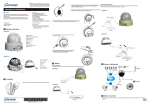
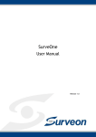
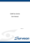
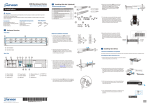
Box Network Camera
Rear View for CAM2311/2331/2331SC/2441/2441SC/2511
3. Connect the lens cable with the DC-Iris/P-Iris connector on the rear side.
QUICK INSTALLATION GUIDE
Hardware Installation
Warning!
Accessories
Quick Installation Guide x1
● Product DVD x1 (including manuals)
● Anchors and Mounting Screws x3
● Camera Stand x1
● RoHs Compliance x1
● Hexagonal Wretch x1 (except for -P series)
● CS-ring x1 ( except for -P series)
● Lens (optional, only supplied for -P series )
●
Only qualified service personnel should install
and service this product in order to avoid risk
of injury from electrical shock and energy hazard.
Observe all ESD (Electro-static Discharge) procedures
during installation to avoid damage to the camera and
its components.
DIO PW
Tools Required
Phillips Screwdriver
● Electric Drill
User-provided Items
LAN Cable
● PC with Windows (XP or above) and web
browsers (Internet Explorer 6.0 or above)
installed
●
1
microSDHC
4. Make four screw holes on a flat interface with the electric drill.
●
Warning
As shown above, the DC-IRIS Black DC power plug must be
matched to the correct camera
with corresponding DC plug.
If matched incorrectly,
irreversible damages may occur!
Hardware Overview
5. Fasten the screws and anchor bolts to secure the camera stand to the surface.
6. Loosen the CS-ring to adjust the desired angle of the camera.
7. Retighten the ring after the desired angle is achieved.
Front View for CAM23xx/24xx/25xx Series
1 Audio In/Out Connector 5 MicroSD/SDHC Card Slot 9 DC-Iris Connector (certain models only)
6 Network Connector
9 P-Iris Connector (CAM2xxxP Series)
10
3 Status LED Indicator
7 I/O Terminal Connector
2 Video Out Connector
4 Reset Button
2
1
8 Power Connector
Installation
1. Remove the lens cover on the camera.
8. Connect the power cord to the power port on the rear side.
Light Sensor
Indent
9. Insert the LAN cable to the LAN port on the rear side.
Protrusion
10. The status LED indicator will blink amber to indicate the boot-up sequence has started. Wait until the
LED is in a steady green state, indicating the camera boot-up is complete.
Rear View for CAM2331P/2331SP/2441P
3
1
Indent
Camera Deployment
Protrusion
DC-IRIS/P-IRIS*
2. Fasten the lens to the camera.
NAS
FTP
Email server
Alarm * Sensor *
DC-IRIS
GND
DIO PW
DI 1
DI 2
DO
RS- 485 A
RS- 485 B
DC12V
Router
AUDIO IN AUDIO OUT
microSDHC 2
microSDHC
Gray Ring
DIO PW
POWER
microSDHC 1
RESET
Warning
As shown above, the P-IRIS Yellow DC power plug with
protrusions or with a gray ring
must be matched to the correct
camera with corresponding DC
plug with indents. If matched
incorrectly, irreversible damages
may occur!
Router
MicroSD
Microphone
* Certain models only
© by Surveon Technology, Inc. All rights reserved.
QMC 2 X X X 0 0 1 1 1
Speaker
4
1
Before You Start
Please prepare a PC with Windows (XP or above) and web browsers (Internet Explorer 6.0 or above)
installed.
3 Logging into the System
The following information will prompt for logging in:
5 Logging out of the System
Logging off of the camera can be performed by closing the browser window. Users can also choose to
click the Logout link located at the top of the screen.
1
Software Installation
1 Obtaining IP Address through the IP Utility
1
The IP address can be obtained using the IP Utility in your product CD :
1. Double click Start SearchToolInstall.exe to begin the utility installation.
2.After the installation is complete, click the Auto Search button or click Camera > Search in the menus.
Note: For details about accessing camera video using QuickTime or Real Player over RTSP,
please refer to the IP Camera user manual.
•Username – The username for the domain. Default is always admin.
•Password – The password for the domain. Default is always admin.
Click OK.
Once successfully logged in, live video displays in the center of your browser.
6 Network Configuration
1
Prepare your internet connectivity by clicking Settings > Network > Network Configuration.
From here you can configure DHCP, static IP, DNS, PPPoE, or DDNS. DDNS is configured by selecting a
DDNS site from its drop-down menu.PPPoE setting changes will take effect after a camera reboot.
Provide the username and password from your Internet Service Provider (ISP) within the PPPoE
section. When PPPoE is applied, the associated DDNS service must be enabled.
The camera search will begin, and a status bar will display the search progress.
3. The details of the camera will display after the search is finished.
4
Installing ActiveX Components in Internet Explorer
You may be prompted to install ActiveX® components when accessing the network camera’s Live View
page; click Yes when prompted. You will be able to access the camera after installation is completed.
Under Windows, this action may require administrator privileges. If the dialog box suggests that you are
not allowed to install ActiveX components, try resolving the problem using the following steps:
1. In Internet Explorer, open Tools > Internet Options > Security. Click the Custom Level button.
2. Search for Download signed ActiveX controls. Under this heading select Prompt and then click OK.
1
Note: (1) The search may take up to 2 minutes, depending on your network configuration.
(2) If your network does not have DHCP service, the default IP address is 192.168.88.10.
2 Connecting to the Network Camera
1
Launch the web browser (Microsoft ® Internet Explorer 6.0 or higher is recommended).
Enter the IP address of the network camera in the address bar of your browser and press enter.
You can also Click the Link to Camera button or click to Camera > Link to Camera in the IP Utility menu bar.
The camera’s live view webpage will open in a browser window.
3. Continue installing the ActiveX components.
4. After installing ActiveX, go to Tools > Internet Options > Trusted Websites > Sites and add the IP
address of the camera.