1
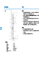
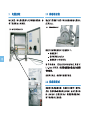
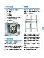
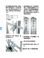
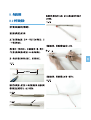
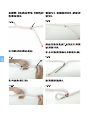
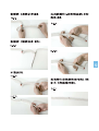
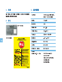
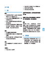
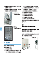
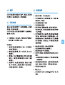
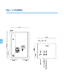
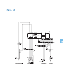
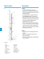
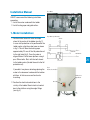
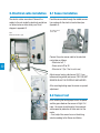
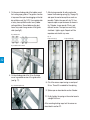
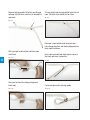
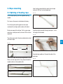
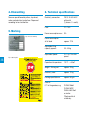
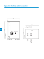
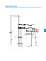
AVANTI Climb Assistance – Type VI
User’s Manual and Installation Instructions
AVANTI Aufstiegshilfe – Typ VI
Benutzerhandbuch und Montageanleitung
2nd Edition: December 2006
2. Ausgabe: Dezember 2006
Manufacturer/ Hersteller:
AVANTI Stigefabrik A/S
Høgevej 19
3400 Hillerød · Denmark
P: +45 4824 9024
F: +45 4824 9124
E: [email protected]
I: www.avanti-online.com
Sales & Services:
Vertrieb und Dienstleistungen:
USA
Avanti Wind Systems, Inc.
5145 South Emmer Drive
New Berlin
Wisconsin 53151
USA
P: +1 (262) 641-9101
F: +1 (262) 641-9161
I: www.avanti-online.com
SPAIN/ SPANIEN
Avanti Wind Systems SL
Poligono Industrial Centrovia
Calle Los Angeles No 15 nave 10
50196 La Muela
Spain/ Spanien
P: +34 976 149524
F: +34 976 149508
I: www.avanti-online.com
CHINA
Avanti Wind Systems
Thousand Ocean Ltd.
Shanghai Rep. Office
266 Xikang Rd. Office
200040 Shanghai
China
P: +86 21 6279 4119
F: +86 21 6279 4534
I: www.avanti-online.com
26
27
System outline
Introduction
Fig. 1
Caution:
• An AVANTI Fall Protection Technician is a
person that has participated in and passed the
AVANTI Fall Protection Technician Course and is
considered an expert.
• A competent person is a person that has fully
read and understood these Climbing Assistance User’s Manual and Installation Instructions.
• The AVANTI Climbing Assistance installation and
service may only be carried through by a
competent person or an expert.
• Once a competent person or an expert installs,
services, or in any other way alters the Climbing
Assistance system, he alone is responsible for
doing so in accordance with these User’s Manual
and Installation Instructions.
1
10
9
5
12
2
4
6
3
13
7
8
28
11
3
19
14
15
17
18
21
List of Signs:
1.
2.
3.
4.
5.
6.
7.
8.
9.
10.
11.
Wall
Ladder
Ladder brackets
Steps
Platform
Resting platform
Person ascending
Harness
Upper end
Top fitting with wheel
Hauling rope
12.
13.
14.
15.
16.
17.
18.
19.
20.
21.
Guide roller
Guide roller
Lower end
Motor
Driving wheel
Power supply
Spring loaded base
Electrical control box
Wheel guard
Sensor with cable
Danger:
• Do not keep or store the hauling rope in direct
sunlight.
• Keep the hauling rope clean and free of oil,
grease and chemicals.
• Only install an earth leakage circuit breaker that
react to pulsing DC.
Installation Manual
Fig. 2 Motor
AVANTI recommend the following installation
procedure.
1. Install the motor underneath the ladder.
2. Install hauling rope and guide rollers.
1. Motor installation:
Fig. 3 Motor positionering
1. Position motor base with motor and rope
wheel at the centre of the ladder (see fig. 2).
In case a fall protection rail is positioned at the
ladder centre, align the motor base as shown
in fig. 3. This will leave the hauling rope
approximately 20 mm off the fall protection rail
to the right side (fig 3). Once the motor is
aligned fasten it to the tower platform using 4
pcs. Ø8mm bolts. Start with the bolt closest
to the ladder centre (the bolt closest to the fall
protection rail).
If possible it may be an advantage placing the
motor in the basement underneath the bottom
platform. In that case use wall anchor for
mounting.
2. Position the electrical control box in the
vicinity of the ladder. Mount electrical control
box to the platform using the angle fittings
(see fig. 4).
20 mm
10-80 mm
110-180 mm
27 29
Fig. 4
Electrical control box
Pulling force
adjustment
On / Off
2. Electrical cable installation
2.1 Sensor installation
The electric cables are marked. Connect the
cables to the rack inside the electrical control box
as follows below or alternatively see Circuit
diagram in appendix B.
Feed the sensor cable through the middle connection underneath the electrical control box (see
Appendix A).
Fig. 5
Electrical control box open
30
Fig. 6 Sensor and
sensor cable
Connect the pulse sensor cable to the electrical
control box as follows:
- Black wire to E 1
- Brown wire to 20 or 28
- Blue wire to 7 (the 7 that is not in use)
Adjust sensor leaving a distance of 0,5-1,5 mm
between driving wheel and sensor. ONLY ADJUST
SENSOR WHILE THE SYSTEM IS UNPLUGGED.
After mounting hauling rope, the sensor may need
adjustment.
2.2 Sensor test
After installing the hauling rope turn on the power
and the green diode on the sensor will light. Pull
rope – the sensor should register the movement
and respond by indication in white and start the
motor.
– If not, adjust the sensor focus on the driving
wheel according to the Sensor installation.
2.3 Motor cable installation
Connect motor cable W1 3, 3-phase to motor as
follows:
- Conductor 1 to U
- Conductor 2 to V
- Conductor 3 to W
- Green-yellow conductor to earth connection
- Conductor 4 and 5 – connect to the terminal.
4 and 5 connects to a thermal switch - hence
the order of connection is of no importance.
- Conductor 6 is not used
3. Rope mounting
1. Bring the top fitting including block, bolts, and
the one end of the hauling rope to the ladder
top. It is often easier to bring up the rope on
the front side and down on the rear side.
Fig. 8
Fig. 7 Motor
31
2.4 Power cable installation
Once the climbing assistant is fully installed
connect power cable to 230 V, 50-60 Hz (1 phase
+ 0 + earth) power outlet.
If additional power cable is attached use a
3x1,5mm2 for phase 0 and earth cable. Secure
power supply with a 10 amp fuse. Use a HPFIrelay with 300mA fault current fuse.
2. On top of the ladder, mount the top fitting as
shown in fig. 8. Using the holes in the top
fitting, the block is positioned just off the rail
centre so it marches the bottom pulling wheel
position. The top fitting and block shall be
mounted so potential injury to fingers etc. is
eliminated. If this is not possible a guard is
needed.
3. Pull the rope through the block and bring
down the rope on the other side of the ladder
while descending.
4. Down at the base platform feed the rope
down through the pulling wheel. Tighten rope
slightly and fasten – do not splice yet.
5. On the non climbing side of the ladder mount
the hauling rope guiders. The guiders function
is to prevent the rope from dragging on the ladder, platforms etc (fig. 9-10). Use a guide roller
at every tower platform and at every ladder
resting platform. Some ladder resting platforms may need a long version of the guide
roller (see fig 9).
Fig. 9 Guide roller
7. After having mounted all rollers and motor
loosen the tensioning spring (fig. 16 page 16)
and open the motor base plate as much as
possible. Tighten the rope with kg. 75. Use
separate rope or rope tensioner as shown in
fig. 15 below. Leave rope for 20 min. and
recheck tension. The rope has most likely
stretched – tighten again. Repeat until the
rope does not stretch any more.
Fig. 12
Rope tensioning a)
Rope tensioning b)
Fig. 10 Guide roller mounted
32
6. On the climbing side of the 1st or 2nd step
mount a guarded version of the guide roller.
(see fig. 11).
Fig. 11 Guarded guide roller
8. Cut of the excess rope leaving an overlap of
50 cm. These 50 is needed for the splicing.
9. Splice rope as described in section 3 below.
10. Finally tighten the spring on the motor base to
a length of 60 mm.
After mounting hauling rope, test the sensor as
described in section 2.2.
3. Rope mounting
3.1 Splicing of hauling rope
Insert splicing needle (black rope) into red rope
minimum 250 mm from red rope-end.
Fig. 13.3
For the rope splicing use the supplied splicing
needle.
First assure the rope is stretched satisfactory.
For clarifying the splicing process one rope
marked with red tape and the other with black.
Seale one rope with red tape. On the same ropeend place a red tape mark minimum 250 mm from
rope end.
Feed the splicing needle through red rope – in the
full length of the needle.
Fig. 13.4
Push
The other rope-end is likewise sealed and marked
with black tape.
Push
33
Fig. 13.1
min 250 mm
Feed splicing needle out through the side of the
read rope.
Insert black rope-end into splicing needle Ø10mm.
Make sure the rope end is firmly placed inside the
needle and lies in the needle sloth.
Fig. 13.2 a
Fig. 13.2 b
Fig. 13.5
Remove splicing needle. Pull black rope through
red rope until the black mark has just passed the
read mark.
This way black rope end gets pulled back into red
rope. The black mark should just be visible.
Fig. 13.8
Fig. 13.6
Red rope is now locked round the black rope –
now change directions and feed red rope end into
black rope like follows:
With your right hand hold red and black rope
mark fixed.
Insert splicing needle into black rope as close to
the black rope mark as possible.
Fig. 13.7 a
34 4
Fig. 13.9
Hold
Pull
Uses your left hand for sliding red rope over
black rope.
Fasten red rope-end in splicing needle.
Fig. 13.7 b
Fig. 13.10
3. Rope mounting
3.1 Splicing of hauling rope
Insert splicing needle (black rope) into red rope
minimum 250 mm from red rope-end.
Fig. 13.3
For the rope splicing use the supplied splicing
needle.
First assure the rope is stretched satisfactory.
For clarifying the splicing process one rope
marked with red tape and the other with black.
Seale one rope with red tape. On the same ropeend place a red tape mark minimum 250 mm from
rope end.
Feed the splicing needle through red rope – in the
full length of the needle.
Fig. 13.4
Push
The other rope-end is likewise sealed and marked
with black tape.
Push
35
Fig. 13.1
min 250 mm
Feed splicing needle out through the side of the
read rope.
Insert black rope-end into splicing needle Ø10mm.
Make sure the rope end is firmly placed inside the
needle and lies in the needle sloth.
Fig. 13.2 a
Fig. 13.2 b
Fig. 13.5
4. Dismantling
6. Technical specifications
Remove rope followed by rollers, top wheel,
motor, and electrical control box. Dispose of
according to local authorities.
Electricity connection:
230 V, 50-60 Hz AC
with earth
(1 phase + 0 + earth)
Fuse:
10 – 16 A
Power consumption max.:
9A
Power consumption
at full load:
approx. 7.2 A
Adjustable lifting
capacity approx.:
35 - 45 kg
5. Marking
Fig. 14 Product marking
Adjustable Speed:
0 +/- ca. 14 m/min
preset
Operational temperature:
-10°C – +55oC
Weight - Driving unit:
approx. 23 kg
Electricity case:
approx. 12 kg
Hauling rope Ø8,8mm:
approx. 68 g/m
Fig. 15 Quick guide
36
45541072 Quickguide climb EN/DE
Gear oil:
0.7 l in the gearbox, e.g.
CLP460 Mobil
CLP460 AGIP
OMALA460 Shell
or similar.
Filled up with oil
at delivery.
User’s Manual
7. Purpose
Caution:
• An AVANTI Fall Protection Technician is a
person that has participated in and passed the
AVANTI Fall Protection Technician Course and is
considered an expert.
• A competent person is a person that has fully
read and understood these Climbing Assistance User’s Manual and Installation Instructions.
• The AVANTI Climbing Assistance installation and
service may only be carried through by a
competent person or an expert.
• Once a competent person or an expert installs,
services, or in any other way alters the Climbing
Assistance system, he alone is responsible for
doing so in accordance with these User’s
Manual and Installation Instructions.
Danger:
• Do not store the hauling rope in direct sunlight.
• Keep the hauling rope clean and free of oil,
grease and chemicals.
• The power supply must not be equipped with an
earth leakage circuit breaker that does not also
react to pulsing DC as this will cause operational
problems.
Not intended for
• Not intended for lifting tools or parts.
• Not intended for people below the age of 18 or
people below the weight of 55 kg.
• Not intended for multiple users at the same time.
• Not to be fastened to body parts or cloth.
The Climbing Assistant is not a fall protection
device. Always wear proper fall protection
equipment (P.P.E.)
Use original parts – no warranty is provided
against damage resulting form reconstruction
or modification of equipment or use of nonoriginal parts.
Functionality
The system includes a motor, a continuous hauling
rope, an electrical control box and a rope clamp.
Hook on to the hauling rope using the rope clamp
and activate the motor by pulling the hauling rope.
A sensor on the pulling wheel then registers the
movement and starts the motor. The hauling rope
then pulls with the pre-adjusted force (e.g. 30 kg.)
no matter the pace and direction of climbing.
Stopping the rope in the same position for 3
seconds, the same sensor register that motion
has stopped, and the pulling force fades out.
8. Daily inspections
Intended use
The AVANTI Climbing Assistance is intended for
personal ascending and descending of long
durations on fixed ladders.
a) Check rope tension spring on motor base
(see fig 16). If spring length is more than 60 mm,
the rope needs tensioning. Tension the spring
with a spanner. If this does not tighten the rope
sufficiently a rope shortening is needed.
See Installation Instructions section 2.7.
37
b) Assure rope is aligned on the guiding rollers
and on the pulling wheel (see fig. 17). The rope
can be aligned on both right and left side.
c) If anything abnormal is observed, take climbing assistance out of use. Correct error before
continuing use.
Fig. 16 Motor base plate
with inductive sensor
and tensioning spring
60 mm
c)
d)
e)
f)
g)
h)
i)
supply (230V-50/60 Hz) and/or turn on the red
switch on the grey electrical control box.
Adjust pull force (1 to 10) on grey electrical
control box (fig. 18). Depending on rope length
this equals approximately 35 - 45 kg.
Connect harness and fall protection device
(P.P.E) as prescribed by manufacturer.
Fasten rope clamp carabiner on harness.
Fasten rope clamp on climbing assistance
rope (fig. 19).
Pull climbing assistance rope to activate motor.
STOP – stand still for 5 seconds.
After use, turn off the power supply and unpluck from power outlet.
Connect the rope clamp carabiner to the harness
D-ring at waist or chest level for best comfort.
38
Fig. 17 Rope alignment.
Rope can be aligned on
both left and right side
App. 14 mm
WARNING!
Keep hauling rope dry and free of oil and grease.
When using the climbing assistance keep
fingers and other body parts, clothes, etc. away
from hauling rope, driving wheel, blocks, etc.
NOTE! The main switch may not be connected/
disconnected several times in rapid succession.
Doing so may damage the electrical installations.
9. Directions for use
Fig. 18
Fig. 19 Rope clamp on rope
Before use read and understand these user’s
instructions.
For use do as follows:
a) Perform the daily inspection described above.
b) Check if green light on motor wheel guard is
on (see fig. 16). If not: connect to the power
Pulling force
adjustment
On / Off
10. Maintenance
12. Trouble shooting
The AVANTI Climbing Assistance is mainly maintenance free. Perform daily inspection as prescribed
above and take action if abnormalities are found.
• Before servicing the motor, motor base, wheel
guard and double guarded rollers un-pluck the
power supply and wait for at least 1 minute.
• The hauling rope does not start when pulled:
1. Pull the hauling rope by hand. If the rope is
stuck – find the blocking factor and fix it.
2. Check that the system has been plugged in.
3. Check that the system is switched on.
4. Check whether the green sensor diode on the
wheel guard is lit - If not, check whether the
electrical installation is done in accordance to
the installation instructions.
5. Pull the hauling rope by hand. If the motor
does not start after pulling the rope firmly
check white sensor on motor guard. The
white sensor indicates movement. If the white
sensor does not indicate movement when
rope is pulled adjust sensor as described in
section 2.1 sensor installation.
Yearly control:
1. Assure al bolts and nuts are fixed (on motor,
electrical control box, rollers, and top fitting).
2. Assure that the compression spring is tightened to L = 60mm (see Daily inspections
section 8 a).
3. Gear oil: - change gear oil every 3 years
(see section 8. System specifications) (year of
last oil replacement is entered in test report
appendix C).
4. Remaining parts should be replaced once
they show sign of being worn out (driving
wheel, hauling rope, etc.). If only a part of the
hauling rope needs replacement, insert a new
section where it is worn.
• Motor and motor wheel goes round, but the
hauling rope does not follow:
1. Check whether the driving wheel is fixed on
the gear shaft.
2. Check whether a rope clamp is stuck in the
top block.
3. Check tension of hauling rope. Is the tensioning spring tightened to approximately 60 mm?
– If not adjust rope as specified in section 8 a)
Daily inspections.
4. Check rope and driving wheel for wear and
tear. If the hauling rope and/or the driving
wheel is worn down they loos grip. Have them
replaced.
5. Check whether the guide rollers are blocked.
11. Yearly control
Once a year a competent person or an expert
must inspect the climbing assistance. If not – this
will void the warranty.
AVANTI runs “Fall Protection Expert classes” on
regular basis. If interested contact AVANTI.
• The tractive force too is small:
1. Check whether the motor electronics is connected in triangle – if not, connect in triangle.
39
Appendix A: Electrical control box overview
380 MM
-A
AE1380.600 lk
SKAB
380 MM
-U22
40 MM
BOTTOM
TORQUE ADJUSTMENT
On
PE
PE
PE
PE
210 MM
I
-R16
Off
O
80 MM
120 MM
40
75 MM
380 MM
60 MM
ECM GUIDE
-W13
-W11 -W17
PULSE SENSOR
MAIN SUPPLY
135 MM
M20 M16
MOTOR
135 MM
M20
Appendix B: Circuits
-U13
L1 L2/ L3 PE
N
+UG-UG
K12 K13 K14
E82EV152 K2C
INVERTER CLIMBING ASSISTANCE
U V W PE. T1 T2
E82ZAFAC
APPLICATION I/O
JUMPER A+B ARE REMOVED FROM
APPLIKATIONS I/O
1U 1I 2U 2I 62 63 9 A1 A2 7 7 A4 59 20 28 E1 E2 E3 E4 E5 E6
-U15
1 3 5
VCCF0
-Q11
2 4 6
3X0,5MM2 CY-OZ
-W16
/
/
/
BLACK
MM
BLUE
BROWN
-W17
SENSOR CABLE
S
5
4
Y/G
3
2
1
-W13
CABLE 3,0 METER OUT
OF CABINET
S
1
3
2
7X1,5MM2 YCY-JZ
MM1
PE PE
/
/
/
1 2
PNP
-B17
U V W PE
t?
2
M
3
1
Y/G
BLUE
BROWN
-W11
-M13
MA2AL90S-6/B14-C140
CABLE 5,5 METER OUT OF CABINET
MOTOR CLIMBING ASSISTANCE
-R16
V+
VSIG.
Variable Resistor 10Kohm/1W
TORQUE ADJUSTMENT
3
PULSE SENSOR
41