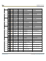
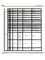
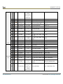
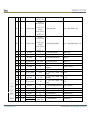
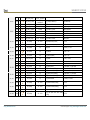
1
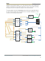
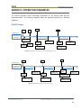
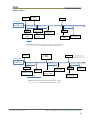
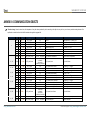
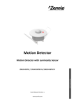
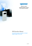
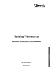
MAXinBOX FC 0-10V FAN 2x Two/Four-Pipe Fan Coil Controller with 0-10 VDC Fan Control Signal Application Program Version: [1.1] User Manual Version: [1.1]_a www.zennio.com USER MANUAL ZCL-FC010F CONTENTS Contents ........................................................................................................................................ 2 Document updates ........................................................................................................................ 3 1 Introduction ............................................................................................................................. 4 1.1 MAXinBOX FC 0-10V FAN ................................................................................................. 4 1.2 Installation ........................................................................................................................ 5 1.3 Start-up and Power Loss................................................................................................... 6 2 Configuration ........................................................................................................................... 7 2.1 General ............................................................................................................................. 7 2.2 Inputs ................................................................................................................................ 8 2.3 Binary Outputs.................................................................................................................. 9 2.4 0-10V Analogue Outputs ................................................................................................ 10 2.5 Fan Coils.......................................................................................................................... 13 2.5.1 Fan Coil x ................................................................................................................. 13 2.5.1.1 General ............................................................................................................ 13 2.5.1.2 Advanced Settings ........................................................................................... 16 2.6 Logic Functions ............................................................................................................... 20 2.7 Thermostats ................................................................................................................... 21 2.8 Manual control ............................................................................................................... 22 Annex I: Independence of the modules ...................................................................................... 26 Annex II: Operation Examples ..................................................................................................... 28 Annex III: Communication objects .............................................................................................. 30 http://www.zennio.com Technical Support: http://zennioenglish.zendesk.com 2 MAXinBOX FC 0-10V FAN DOCUMENT UPDATES Version Changes Page(s) Changes in the application program: • [1.1]_a Optimisation of the timed actions management - in the logic functions module. General revision of texts and styles http://www.zennio.com - Technical Support: http://zennioenglish.zendesk.com 3 MAXinBOX FC 0-10V FAN 1 INTRODUCTION 1.1 MAXinBOX FC 0-10V FAN MAXinBOX FC 0-10V FAN from Zennio is a versatile KNX multi-function actuator that aims at fulfilling the climate control needs of KNX environments with integrated fan coil units where the fan speed is controlled through an analogue 0-10 VDC signal, while the gates of the water pipes need to be controlled through binary outputs (relays). The actuator provides two analogue outputs and four binary outputs, all of which can be enabled and configured independently, which lets the integrator combine them as desired to control up to 2 two-pipe or four-pipe fan coil units. At a glance, the most outstanding features of MAXinBOX FC 0-10V FAN are: 2 independent analogue 0-10 VDC outputs, 4 independent binary (relay) outputs, 2 independent fan coil functions, to control up to two fan coil units by means of the above analogue and binary outputs. 4 multi-purpose inputs, each of them configurable as: Temperature probe, Binary input (i.e., pushbuttons, switches, sensors), Motion detector. 10 customisable, multi-operation logic functions. 2 independent thermostats. Manual operation / supervision of the relay outputs and the 0-10 VDC signals through the on-board pushbuttons and LEDs. The MAXinBOX FC 0-10V FAN application program focuses on the control of fan coil drives that consist of two or four pipes (each with its own open/close valve) and a fan http://www.zennio.com Technical Support: http://zennioenglish.zendesk.com 4 MAXinBOX FC 0-10V FAN system whose speed is controlled through a 0 to 10 VDC analogue signal (more voltage means more speed). 1.2 INSTALLATION MAXinBOX FC 0-10V FAN connects to the KNX bus through the on-board KNX connector. Once the device is provided with power from the KNX bus, both the individual address and the associated application program may be downloaded. This device does not need any additional external power since it is entirely powered through the KNX bus. 1. Multi-Purpose Inputs. 2. 0-10 VDC Outputs. 3. Output Status LED Indicator. 4. Output Control Button. 5. Prog./Test LED. 6. Binary Outputs. 7. KNX Bus Connector. 8. Prog./Test button. Figure 1 MAXinBOX FC 0-10V. http://www.zennio.com Technical Support: http://zennioenglish.zendesk.com 5 MAXinBOX FC 0-10V FAN The main elements of the device are described next. Test/Prog. pushbutton (8): a short press on this button sets the device into the programming mode, making the associated LED (5) light in red. Note: if this button is held while plugging the device into the KNX bus, the device will enter into safe mode. In such case, the LED will blink in red every 0.5 seconds. Outputs (2) and (6): output ports for the insertion of the stripped cables of the systems being controlled by the actuator (see sections 2.3 and 2.4). Please secure the connection by means of the on-board screws. For detailed information about the technical features of the device and for safety instructions and on the installation process, please refer to the Datasheet bundled with the original packaging of the device and also available at www.zennio.com. 1.3 START-UP AND POWER LOSS During the start-up of the device, the Test/Prog. LED will blink in blue colour for a few seconds before MAXinBOX FC 0-10V FAN is ready. External orders will not be executed during this time, but afterwards. Depending on the configuration, some specific actions will also be performed during the start-up. For example, the integrator can set whether the outputs should switch to a particular state and whether the device should send certain objects to the bus after the power recovery. Please consult the next sections of this document for further details. On the other hand, when a bus power failure takes place, MAXinBOX FC 0-10V FAN will interrupt any pending actions, and will save its state so it can be recovered once the power supply is restored. http://www.zennio.com Technical Support: http://zennioenglish.zendesk.com 6 MAXinBOX FC 0-10V FAN 2 CONFIGURATION 2.1 GENERAL ETS PARAMETERISATION Figure 2 General screen. After importing the corresponding database in ETS and adding the device into the topology of the desired project, the configuration process begins by right-clicking into the device and selecting Edit parameters. This will bring the window shown in Figure 2. From this screen it is possible to activate/deactivate all the required functionality through the corresponding checkboxes: Once activated, Inputs, Binary Outputs, 0-10V Analog Outputs, Fan Coils, Logical Functions, Thermostats and Manual Control (enabled by default) bring additional tabs to the menu on the left. These functions and their parameters will be explained in later sections of this document. Sending of Indication Objects (0 and 1) on Bus Voltage Recovery: this parameter lets the integrator activate two new communication objects (“Reset 0” and “Reset 1”), which will be sent to the KNX bus with values “0” and “1” respectively whenever the device begins operation (for example, after a bus power failure). It is possible to parameterise a certain delay for this sending (0 to 255 seconds). http://www.zennio.com Technical Support: http://zennioenglish.zendesk.com 7 MAXinBOX FC 0-10V FAN 2.2 INPUTS MAXinBOX FC 0-10V FAN provides four analogue/digital inputs, each configurable as a: Binary Input, for the connection of a pushbutton or a switch/sensor. Temperature Probe, to connect a temperature sensor (model ZN1ACNTC68 S/E/F from Zennio). Motion Detector, to connect a motion detector (models ZN1IO-DETEC-P and ZN1IO-DETEC-X from Zennio). Important: older models of the Zennio motion detector (e.g., ZN1IO-DETEC and ZN1IO-DETEC-N) will not work properly with MAXinBOX FC 0-10V FAN. For detailed information about the functionality and the configuration of the parameters involved, please refer to the following specific manuals, available under the MAXinBOX FC 0-10V FAN product section, at the Zennio homepage, www.zennio.com): “Binary Inputs in MAXinBOX FC 0-10V FAN”, “Temperature Sensor in MAXinBOX FC 0-10V FAN”, “Motion Detector in MAXinBOX FC 0-10V FAN”. http://www.zennio.com Technical Support: http://zennioenglish.zendesk.com 8 MAXinBOX FC 0-10V FAN 2.3 BINARY OUTPUTS MAXinBOX FC 0-10V FAN incorporates four binary outputs, each of which can be enabled and configured in parameters independently. Although in this device they are offered with the aim of controlling the gate valves of the fan coil tubes (up to four), their parameterisation is similar to that of the individual relay outputs of any other MAXinBOX actuators. Note that they all work independently, although it is possible to group them as required (for example, to pen a gate valve when another one closes) through joint group addresses and to configure each of them as “normally open” or “normally closed”, to open / close its gate valve on the reception of a “0” or of a “1”. Practical usage examples of the different outputs and modules all together are offered in “Annex I: Independence of the modules” of this user manual. Please refer to the specific manual “Binary Outputs in MAXinBOX FC 0-10V FAN” (available at the Zennio homepage, www.zennio.com) for detailed information. http://www.zennio.com Technical Support: http://zennioenglish.zendesk.com 9 MAXinBOX FC 0-10V FAN 2.4 0-10V ANALOGUE OUTPUTS MAXinBOX FC 0-10V FAN incorporates two analogue voltage outputs that provide a voltage signal in the range 0 to 10 VDC. This voltage will be in accordance to the percentage values that are received through a specific communication object. Each analogue output can be enabled or disabled in parameters, and is intended to control the fan speed of one fan coil unit. One on-board LED indicator is offered per output to show the status: it will remain off while the output signal is 0V, and on while it is 10V. Under intermediate values, it will blink with variable rates (according to the voltage). ETS PARAMETERISATION After enabling “0-10V Analog Outputs” in the General screen (see section 2.1), a new tab will be incorporated into the tree on the left. Figure 3 0-10V Analog Outputs - Configuration. The two analogue outputs can be activated independently by marking the checkboxes. This also brings new tabs to the tree. Figure 4 0-10V Analog Output X – Configuration. After enabling any of them, two objects are included by default: “[AOx] Output Value (Control)”: this object is supposed to receive percentage values from the KNX bus, making the device generate a voltage output between 0 V and 10 V (proportional to the percentage value). http://www.zennio.com Technical Support: http://zennioenglish.zendesk.com 10 MAXinBOX FC 0-10V FAN “[AOx] Output Value (Status)”: status object that shows, in terms of percentage, the current value of the analogue output signal. This object is automatically sent to the bus after receiving a new voltage setpoint, and when the output status changes due to a lock order. The following parameters can be configured from the corresponding tab: Figure 5 0-10V Analog Output X – Configuration (in detail). Enable Lock by Object: when this checkbox is marked, the one-bit object “[AOx] Lock” turns visible, as well as one more parameter: Lock Action: sets the particular state (“No Change” / “On” / “Off”) the output will adopt upon the reception of the value “1” through the “[AOx] Lock” object. If set to “On”, the desired Output Value needs to be configured, in terms of percentage. Note: while an output is locked, further voltage setpoints are ignored (the device will respond with the current status of the output). Initialization: brings the option to set the output to a particular state at the start-up of the actuator. Default: off after an ETS download, and unchanged after a bus power failure. Custom: this option brings two new parameters: http://www.zennio.com Technical Support: http://zennioenglish.zendesk.com 11 MAXinBOX FC 0-10V FAN • Initial Status: “Previous”, “On”, “Off”, after either an ETS download or a bus power failure (last will be off on the very first start-up). When selecting “On”, the desired Output Value needs to be configured, in terms of percentage. • Send Status: when marked, the status object will be sent to the bus with a customisable Delay, from 0 to 600 ds, 0 to 3600 s, 0 to 1440 min or 0 to 24 hours (3 seconds by default). Note: the lock status is preserved after a bus failure. In case of conflict between the state defined for the lock function and the state defined for the initialization, the lock state prevails. That is, if a bus failure occurs with an output locked, after the bus recovery the output will have the same value, independently of the Initial status defined in the Initialization function. http://www.zennio.com Technical Support: http://zennioenglish.zendesk.com 12 MAXinBOX FC 0-10V FAN 2.5 FAN COILS MAXinBOX FC 0-10V FAN incorporates two independent fan coil functions that implement all the logic involved in the control of up to two fan coil units. ETS PARAMETERISATION After enabling “Fan Coils” in the General screen (see section 2.1), a new tab will be incorporated into the tree on the left. Figure 6 Fan Coils - Configuration. The two fan coil functions can be activated independently by marking their checkboxes. This brings some more tabs to the tree. 2.5.1 FAN COIL x Each fan coil function requires setting some general parameters and, optionally, some advanced parameters. All of them are described next. 2.5.1.1 GENERAL Among other options regarding the fan coil operation modes and the values and delays involved in the opening and closing of the valves, the general parameters bring the option to set two offsets: The minimum value of the control variable that should activate the fan, i.e., the minimum percentage value that will be required to make the actuator actually operate the fan; values under that minimum will be ignored by the actuator. This is called “Offset 1” in Figure 7. The minimum fan speed, i.e., the minimum voltage (in percentage) that permits appreciating motion in the fan. This parameter is useful when the fan is not able to effectively start motion with voltage values lower than a certain percentage. This is called “Offset 2” in Figure 7. http://www.zennio.com Technical Support: http://zennioenglish.zendesk.com 13 MAXinBOX FC 0-10V FAN % Output 100 % Close valve Open valve Offset 2 100 % Offset 1 Offset 2 % Input Figure 7 Output percentage value depending on the input setpoint and the offsets. ETS PARAMETERISATION The Configuration screen (see Figure 8) is accessible by default after enabling the Fan Coil function. It contains the following parameters: Figure 8 Fan Coil X – Configuration. http://www.zennio.com Technical Support: http://zennioenglish.zendesk.com 14 MAXinBOX FC 0-10V FAN Type of Fan Coil: sets the type of the fan coil. The options are: “2 pipes” and “4 pipes”. Under “2 pipes”, it is necessary to set the operating Mode: Mode: sets the operating mode of the fan coil system. The options are: “Cooling”, “Heating” or “Both”. This parameter is only available for two-pipe fan coils (in the case of four-pipe fan coils, both modes are always available). Depending on the value of Type and Mode and according to Table 1, either one set of objects or another will be available. 2 tubes Object Cooling Heating [FCx] Mode and Mode (Status) [FCx] Control Variable (Cooling) [FCx] Valve Control x 4 tubes x x x x x x x x x x [FCx] Control Variable (Heating) Both [FCx] Valve Control (Cooling) x [FCx] Valve Control (Heating) x Table 1 Fan Coil communication objects depending on the Type and Mode. Note: the values received through “[FCx] Control Variable (Cooling)” will only have effect if Cooling is the current mode, while the values received through “[FCx] Control Variable (Heating)” will not be applied, although the will be taken into account when the mode changes to Heating. The same happens for the opposite case. Please refer to “Annex II: Operation Examples” for some operation examples where these objects are received in different scenarios. Value Sent to Open/Close Valve: sets the values required to open and close the valve. The options are: “0 = Close Valve; 1 = Open Valve” (by default) and “0 = Open Valve; 1 = Close Valve”. The following parameters define two offset values applied to fan speed control: Minimum Control Variable Value that Activates the Fan: from 0 to 100% (10% by default). http://www.zennio.com Technical Support: http://zennioenglish.zendesk.com 15 MAXinBOX FC 0-10V FAN Minimum Fan Speed: from 0 to 100% (20% by default). This value must be higher or equal than the Minimum Control. Note: both offsets must be lower than the Maximum Fan Speed parameter (see 2.5.1.2). Depending on the mode, the following delays must be configured: Delay for Fan Activation when Valve Opens: time to wait since the valve opens until the fan can be turned on. This delay must be configured for both Cooling and Heating. The allowed values are: 0 to 600 ds, 0 to 3600 s, 0 to 1440 min or 0 to 24 hours. Delay for Fan Deactivation when Valve Closes: time to wait since the valve closes until the fan should be turned off. This delay must be configured for both Cooling and Heating. The allowed values are: 0 to 600 ds, 0 to 3600 s, 0 to 1440 min or 0 to 24 hours. Minimum Delay for the mode change: minimum time the device should wait between the order to close the valve (under the old mode) and the order to open the valve (in the new mode). The allowed values are: 0 to 600 ds, 0 to 3600 s, 0 to 1440 min or 0 to 24 hours This parameter is only visible when the two modes are available (i.e., with a two-pipe fan coil with both modes, or with a four-pipe fan coil). 2.5.1.2 ADVANCED SETTINGS Among other options, the advanced settings permit the definition of a maximum fan speed level, which is set in terms of percentage. If set, any fan regulation order greater than this value will lead the output to the maximum, as shown in Figure 9. One more advanced feature is the option to keep the fan in motion after the valve is closed (i.e., when the setpoint is under the minimum value that activates the fan, or Offset 1). This requires setting in parameters the desired constant speed for the fan when this occurs (this fan speed can be changed at runtime when required). Figure 10 illustrates this behaviour. http://www.zennio.com Technical Support: http://zennioenglish.zendesk.com 16 MAXinBOX FC 0-10V FAN % Output 100 % Open valve Close valve Max. Offset 2 Offset 1 Offset 2 Max 100 % % Input Figure 9 Output percentage depending on the input setpoint, the two offsets and the maximum. % Output Max. Close valve 100 % Open valve Offset 2 Cooling minimum Offset 1 Offset 2 Max. 100 % % Input Figure 10 Output percentage depending on the input setpoint, the two offsets and the fan speed with the valve closed. It is also possible to define a forced position in parameters, which allows setting (on request through the corresponding object) the fan speed to a pre-set value (with no action on the valves). Under the forced position mode: The valves remain in the state they were before the forced position order. Any control order is ignored, but taken into account after leaving this mode. http://www.zennio.com Technical Support: http://zennioenglish.zendesk.com 17 MAXinBOX FC 0-10V FAN The forced position resumes after a power failure. An Off order will be performed as usual, and leads to leaving the forced position mode. Upon the reception of On order, the fan control order will be sent again, as well as the On status, but there will be no action on the valves. The pre-set output value for this mode does not depend on the offsets, being up to the integrator whether to set a value greater than Offset 1. Mode switch orders are not executed until the forced position mode is left, although they are responded by sending the mode status object. If the fan coil module is off, forced position orders are ignored. ETS PARAMETERISATION After enabling “Advanced Settings” in the Configuration screen of the fan coil function, a new tab will be incorporated into the tree on the left. Figure 11 Fan Coil X – Advanced Settings. The following parameters can be configured: Fan Coil always On?: sets whether the fan coil will always be on or not. If this option is set to “No” (by default), the fan coil turns on/off when receiving a “1” or “0” through the object “[FCx] On/Off”, respectively. The state of the fan coil can be obtained by reading the “[FCx] On/Off (Status)” communication object any time. http://www.zennio.com Technical Support: http://zennioenglish.zendesk.com 18 MAXinBOX FC 0-10V FAN If this option is set to “Yes”, the Fan Coil remains always on, waiting for regulation orders. The objects “[FCx] On/Off” and “[FCx] On/Off (Status)” are not available. Please refer to section “Annex II: Operation Examples” for some operation examples where these objects are received in different scenarios. Maximum Fan Speed: when enabled, sets a maximum value for the fan speed through the following parameter: Maximum: from 0 to 100% (by default). Enable Forced Position Object: when enabled, a new communication object (“[FCx] Forced Position”) becomes available. When it receives the value “1” and the system is on, the system enters the forced position mode, and the fan speed is set to the value set by the following parameter: Cooling/Heating Fan Speed: from 0 (by default) to 100%. Keep Fan Activated in Cooling Mode when Valve Closes: if enabled, the fan speed will change to a certain parameterisable value whenever the control order received is under Offset 1 (Minimum Control Variable Value that Activates the Fan), instead of being set to 0%. A new communication object is added to change this fan speed at runtime (“[FCx] Fan Speed when Valve Closed (Cooling)”). Fan Speed: from 0 to 100% (20% by default). http://www.zennio.com Technical Support: http://zennioenglish.zendesk.com 19 MAXinBOX FC 0-10V FAN 2.6 LOGIC FUNCTIONS MAXinBOX FC 0-10V FAN allows enabling and fully customising up to ten different logic functions with their corresponding input objects, whose size can be 1 bit, 1 byte, 2 bytes or 4 bytes. Please refer to the specific manual “Logic Functions in MAXinBOX FC 0-10V FAN” (available at the Zennio homepage, www.zennio.com) for detailed information about the functionality and the configuration of the related parameters. http://www.zennio.com Technical Support: http://zennioenglish.zendesk.com 20 MAXinBOX FC 0-10V FAN 2.7 THERMOSTATS MAXinBOX FC 0-10V FAN implements two Zennio thermostats which can be independently enabled and fully customised. Please refer to the specific manual “Zennio Thermostat for MAXinBOX FC 0-10V FAN” (available at the Zennio homepage, www.zennio.com) for detailed information about the functionality and the configuration of the related parameters. http://www.zennio.com Technical Support: http://zennioenglish.zendesk.com 21 MAXinBOX FC 0-10V FAN 2.8 MANUAL CONTROL MAXinBOX FC 0-10V FAN allows manually switching the state of its binary and 0-10V analogue outputs through the respective pushbuttons on the top of the device. A specific pushbutton is therefore available per output. Manual operation can be done in two different ways, named as Test On Mode (for testing purposes during the configuration of the device) and Test Off Mode (for a normal use, anytime). Whether both, only one or none of these modes should be accessible can be parameterised in ETS. Moreover, it is possible to enable a specific binary object for locking and unlocking the manual control in runtime. Note: The Test Off mode will be active (unless it has been disabled by parameter) after a download or a reset, with no need of a specific activation – the pushbuttons will respond to user presses from the start. On the contrary, switching to the Test On mode (unless disabled by parameter) needs to be done by long-pressing the Prog./Test button (for at least three seconds), until the LED is no longer red and turns yellow. From that moment, once the button is released, the LED light will remain green to confirm that the device has switched from the Test Off mode to the Test On mode. After that, an additional press will turn the LED yellow and then off, once the button is released. This way, the device leaves the Test On mode. Note that it will also leave this mode if a bus power failure takes place. Test Off Mode Under the Test Off Mode, the outputs can be controlled through both their communication objects and the actual pushbuttons located on the top of the device. When one of these buttons is pressed, the output will behave as if an order had been received through the corresponding communication object, so it has no effect if the output is locked or under alarm status. The status objects of the different functions will still be sent in the usual way. http://www.zennio.com Technical Support: http://zennioenglish.zendesk.com 22 MAXinBOX FC 0-10V FAN The action performed depends on the output type and, in the case of 0-10V analogue outputs, on the press type. For both outputs types, the presses have no effect if the output is disabled in parameters. Binary output: a simple press (short or long) will make the output switch its on-off state, with independence of the state of the other binary outputs. This will be reported to the KNX bus through the corresponding status object, if enabled. 0-10V analogue output: the action depends on the type of press: Short press: it is equivalent to a 0% or 100% regulation order through the “[AOx] Output Value (Control)”, causing a 0V or 10V output signal. If the current state is greater than 0% the regulation order will be 0% (0V), while if the current state is 0% the regulation will be 100% (10V). Long press: if the button is long-pressed, the actuator will start increasing or decreasing the fan speed progressively as long as the button is being held. The direction of the regulation with every new long press will be downwards (i.e., a decrease of the fan speed), unless the current state is 0% (in such case, the regulation will consist in an increase). The updated state object will be sent once the button is released, or when the maximum / minimum value is reached. The complete regulation cycle (0% to 100% or vice versa) takes 10 seconds. Disabled output: outputs disabled in parameters will not react to button presses under the Test Off mode. Regarding the lock, timer, alarm and scene functions the device will behave under the Test Off mode as usual. Button presses during this mode are entirely analogous to the reception of the corresponding orders from the KNX bus. Test On Mode After entering the Test On mode, it will only be possible to control the outputs through the on-board pushbuttons. Orders received through communication objects will be ignored, with independence of the output they are addressed to. http://www.zennio.com Technical Support: http://zennioenglish.zendesk.com 23 MAXinBOX FC 0-10V FAN Depending on the type of output, binary or analogue, the reactions to the button presses will differ. Binary output: short or long-pressing the button will commute the on-off state of the relay. 0-10V analogue output: the behaviour is the same as described for the Test Off Mode, except that the fan status objects do not change (they will be updated when leaving the Test On Mode). Disabled output: under the Test On mode, disabled outputs will behave as if they were enabled, thus, as described above (depending on whether they are binary or analogue outputs). The lock, timer, alarm and scene functions will not work while the device is under the Test On mode, but will be taken into account when leaving the Test On Mode. Status objects will not be sent to the bus, either. Important: the device is factory delivered with both manual modes (Test Off and Test On) enabled. ETS PARAMETERISATION The Manual Control is configured from a specific tab which can be enabled from the General screen (see section 2.1). Figure 12 Manual Control. The only two parameters are: Manual Control: options are “Disabled”, “Only Test Mode Off”, “Only Test Mode On” and “Both Test Mode Off and On” (default). Depending on the selection, the device will permit using the manual control under the Test Off, the Test On, or either of the two modes. Note that, as stated before, using the http://www.zennio.com Technical Support: http://zennioenglish.zendesk.com 24 MAXinBOX FC 0-10V FAN Test Off mode does not require any special action, while switching to the Test On mode does require long-pressing the Prog./Test button. Lock Manual Control: unless the above parameter has been “Disabled”, enabling the Lock Manual Control parameter will provide a runtime procedure for locking the manual control. When this checkbox is enabled, object “Manual Control Lock” turns visible, as well as two more parameters: Value: defines whether the lock/unlock of the manual control should take place respectively upon the reception (through the aforementioned object) of values “0” and “1”, or the opposite. Initialization: sets how the manual control should remain after the device start-up (after an ETS download or a bus power failure): “Unlocked”, “Locked” or, by default, “Last Value” (on the very first start-up, this will be Unlocked). http://www.zennio.com Technical Support: http://zennioenglish.zendesk.com 25 MAXinBOX FC 0-10V FAN ANNEX I: INDEPENDENCE OF THE MODULES The following figures illustrate how the communication objects and group addresses of the fan coil and the outputs modules should be linked depending on the system to control. Two-Pipe Fan Coil System [AOY] Output Value (Control) [AOY] Output Value (Status) Analogue Output “y” [FCx] On/Off [FCx] Control Variable (Cooling) [FCx] Control Variable (Heating) [FCx] Mode Fan Coil Module “x” [FCx] Fan Speed 0-10 VDC [FCx] On/Off (Status) [FCx] Valve Control [OZ] On/Off [OZ] On/Off (Status) Binary Output “z” On/Off Four-Pipe Fan Coil System [AOY] Output Value (Control) [AOY] Output Value (Status) Analogue Output “y” [FCx] On/Off [FCx] Control Variable (Cooling) [FCx] Control Variable (Heating) [FCx] Mode 0-10 VDC [FCx] Fan Speed [FCx] On/Off (Status) Fan Coil Module “x” [FCx] Valve Control (Heating) ) [OZ1] On/Off [FCx] Valve Control (Cooling) [OZ2] On/Off [OZ1] On/Off (Status) Binary Output “z1” On/Off [OZ2] On/Off (Status) Binary Output “z2” On/Off It is worth emphasising that the two fan coil modules are completely independent of the analogue and binary outputs modules. It is up to the integrator whether to control the fan coil module together with the built-in outputs modules (by grouping their http://www.zennio.com Technical Support: http://zennioenglish.zendesk.com 26 MAXinBOX FC 0-10V FAN respective communication objects) or not. This makes the device more versatile and capable of controlling fan coils systems with their own valve / fan actuators by linking the objects of the fan coil module to the objects of the external actuators. The same applies to the built-in thermostat module, which can be optionally linked to the other internal modules and commanded from an external touchscreen or room controller, as the following example shows: Temperature Probe Input “i” [I I] Current Temperature [TN] Mode (Status) [TN] Control Variable (Heating) [TN] Control Variable (Cooling) [TN] Temperature Reference Thermostat “n” [TN] On/Off (status) [TN] On/Off [TN] Setpoint [TN] Mode [AOY] Output Value (Status) [AOX] Output Value (Control) Analogue Output “y” [FCX] On/Off [FCX] Control Variable (Cooling) [FCX] Fan Speed Fan Coil Module [FCX] Control Variable (Heating) [FCX] Mode “x” [FCX] On/Off (Status) [FCX] Valve Control (Heating) [OZ1]On/Off [FCX] Valve Control (Cooling) [OZ2]On/Off http://www.zennio.com 0-10 VDC [OZ1] On/Off (Status) Binary Output “z1” On/Off [OZ2] On/Off (Status) Binary Output “z2” On/Off Technical Support: http://zennioenglish.zendesk.com 27 MAXinBOX FC 0-10V FAN ANNEX II: OPERATION EXAMPLES The device operation varies notoriously depending on the current state and the parameterisation. The following diagrams show the expected behaviour in different situations. On/Off Orders Off On Off On FC MODULE Off. Heating mode. %Control = 0 tdeactivation heating Fan Speed = 0% On (status) Fan Speed = 0% Off (status) On (status) tdeactivation heating Valve Control = Close t Fan Speed = 0% Off (Status) Valve Control = Close Figure 13 On/Off: 2 pipes (any mode), initial value = 0%. Off On On FC MODULE Off. Cooling mode. % Heat. Ctrl > 0 tactivation cooling Fan Speed > 0% On (status) Valve Control (Cooling) = Open tactivation cooling On (status) Fan Speed > 0% Valve Control (Cooling) = Open tdeactivation cooling Off (status) t Fan Speed = 0% Valve Control (Cooling) = Close Valve Control (Heating) = Close Figure 14 On/Off: 4 pipes, initial value > 0%. http://www.zennio.com Technical Support: http://zennioenglish.zendesk.com 28 MAXinBOX FC 0-10V FAN Mode orders Control Variable (heating) V ≥ Offset1 Heating Cooling FC MODULE On. Cooling mode. tdeactivation cooling tactivation heating Fan Speed = 0% Heating (status) Valve Control = Close tdeactivation heating t Cooling (status) Fan Speed V>0% Valve Control = Open Valve Control = Close tchange mode Fan Speed = Vp Figure 15 Change mode when Fan Coil is On: 2 pipes (“Both”). tchange < tdeactivation. Fan Speed=Vp when valve closes. Control Variable (cooling) V ≥ Offset1 Cooling FC MODULE On. Heating mode. tdeactivation heating tactivation cooling Cooling (status) Valve Control (Heating) = Close Heating Fan Speed V>0% Fan Speed = Vp Valve Control (Cooling) = Open tchange mode No further actions because “Control Variable (heating)” = 0% tdeactivation cooling Heating (status) t Fan Speed = 0% Valve Control (Cooling) = Open Figure 16 Change mode when Fan Coil is On: 4 pipes. tchange > tdeactivation. Fan Speed=Vp when valve closes. http://www.zennio.com Technical Support: http://zennioenglish.zendesk.com 29 MAXinBOX FC 0-10V FAN ANNEX III: COMMUNICATION OBJECTS “Functional range” shows the values that, with independence of any other values permitted by the bus according to the object size, may be of any use or have a particular meaning because of the specifications or restrictions from both the KNX standard or the application program itself. Number 1 Size 1 Bit 2 1 Bit I/O Flags CT--- Data type (DPT) DPT_Trigger Functional Range 0/1 Reset 0 Name Function Voltage Recovery -> Sending of 0 CT--- DPT_Trigger 0/1 Reset 1 Voltage Recovery -> Sending of 1 1 Bit I C--W- DPT_Switch 0/1 Manual Control Lock 0 = Lock; 1 = Unlock 4 1 Bit 1 Byte I I C--WC--W- DPT_Switch DPT_SceneControl 0/1 0-63; 128-191 Manual Control Lock [Thermostat] Scene Input 0 = Unlock; 1 = Lock Scene Value 5, 35 2 Byte I C--W- DPT_Value_Temp -273.00 - 670760.00 [Tx] Temperature Source 1 External Sensor Temperature 6, 36 7, 37 2 Byte 2 Byte I O C--WCTR-- DPT_Value_Temp DPT_Value_Temp -273.00 - 670760.00 -273.00 - 670760.00 [Tx] Temperature Source 2 [Tx] Effective Temperature External Sensor Temperature Effective Control Temperature [Tx] Special Mode 1-byte HVAC Mode 3 8, 38 1 Byte I C--W- DPT_HVACMode 1=Comfort 2=Standby 3=Economy 4=Building Protection 9, 39 1 Bit 1 Bit I I C--WC--W- DPT_Trigger DPT_Switch 0/1 0/1 [Tx] Special Mode: comfort [Tx] Special Mode: comfort 0 = Nothing; 1 = Trigger 0 = Off; 1 = On 1 Bit I C--W- DPT_Trigger 0/1 [Tx] Special Mode: standby 0 = Nothing; 1 = Trigger 1 Bit I C--W- DPT_Switch 0/1 [Tx] Special Mode: standby 0 = Off; 1 = On 1 Bit 1 Bit I I C--WC--W- DPT_Trigger DPT_Switch 0/1 0/1 [Tx] Special Mode: economy [Tx] Special Mode: economy 0 = Nothing; 1 = Trigger 0 = Off; 1 = On 1 Bit I C--W- DPT_Trigger 0/1 [Tx] Special Mode: protection 0 = Nothing; 1 = Trigger 13, 43 1 Bit 1 Bit I I C--WC--W- DPT_Switch DPT_Window_Door 0/1 0/1 [Tx] Special Mode: protection [Tx] Window Status (input) 0 = Off; 1 = On 0 = Closed; 1 = Open 14, 44 1 Bit I C--W- DPT_Trigger 0/1 [Tx] Comfort Prolongation 0 = Nothing; 1 = Timed Comfort [Tx] Special Mode Status 1-byte HVAC Mode [Tx] Setpoint Thermostat Setpoint Input [Tx] Basic Setpoint Reference Setpoint 10, 40 11, 41 12, 42 15, 45 16, 46 1 Byte O CTR-- DPT_HVACMode 2 Byte I C--W- DPT_Value_Temp 1=Comfort 2=Standby 3=Economy 4=Building Protection -273.00 - 670760.00 2 Byte I C--W- DPT_Value_Temp -273.00 - 670760.00 http://www.zennio.com Technical Support: http://zennioenglish.zendesk.com MAXinBOX FC 0-10V FAN 17, 47 1 Bit I C--W- DPT_Step 18, 48 2 Byte I C--W- DPT_Value_Tempd 19, 49 20, 50 2 Byte 2 Byte O O CTR-CTR-- DPT_Value_Temp DPT_Value_Temp 21, 51 2 Byte O CTR-- DPT_Value_Tempd 1 Bit I C--W- DPT_Reset 0/1 [Tx] Setpoint Reset Reset Setpoint to Default 23, 53 1 Bit 1 Bit I I C--WC--W- DPT_Reset DPT_Heat_Cool 0/1 0/1 [Tx] Offset Reset [Tx] Mode Reset offset 0 = Cool; 1 = Heat 24, 54 1 Bit O CTR-- DPT_Heat_Cool 0/1 [Tx] Mode Status 0 = Cool; 1 = Heat 25, 55 26, 56 1 Bit 1 Bit I O C--WCTR-- DPT_Switch DPT_Switch 0/1 0/1 [Tx] On/Off [Tx] On/Off Status 0 = Off; 1 = On 0 = Off; 1 = On 27, 57 1 Byte O CTR-- DPT_Scaling 0% - 100% [Tx] Control Variable (Cool) PI Control (Continuous) 28, 58 1 Byte O CTR-- DPT_Scaling 0% - 100% [Tx] Control Variable (Heat) PI Control (Continuous) 29, 59 1 Bit 1 Bit O O CTR-CTR-- DPT_Switch DPT_Switch 0/1 0/1 [Tx] Control Variable (Cool) [Tx] Control Variable (Cool) 2-Point Control PI Control (PWM) 1 Bit O CTR-- DPT_Switch 0/1 [Tx] Control Variable (Heat) 2-Point Control 31, 61 1 Bit 1 Bit O O CTR-CTR-- DPT_Switch DPT_Switch 0/1 0/1 [Tx] Control Variable (Heat) [Tx] Additional Cool PI Control (PWM) Temp >= (Setpoint+Band) => "1" 32, 62 1 Bit O CTR-- DPT_Switch 0/1 [Tx] Additional Heat Temp <= (Setpoint-Band) => "1" 33, 63 1 Bit O CTR-- DPT_Switch 0/1 [Tx] PI State (Cool) 34, 64 1 Bit O CTR-- DPT_Switch 0/1 [Tx] PI State (Heat) 65, 69, 73, 77 2 Byte O CTR-- DPT_Value_Temp -273.00 - 670760.00 [Ix] Current Temperature Temperature sensor value 66, 70, 74, 78 1 Bit O CTR-- DPT_Alarm 0/1 [Ix] Overcooling 0 = No Alarm;1 = Alarm 67, 71, 75, 79 68, 72, 76, 80 1 Bit 1 Bit O O CTR-CTR-- DPT_Alarm DPT_Alarm 0/1 0/1 [Ix] Overheating [Ix] Probe Error 0 = No Alarm;1 = Alarm 0 = No Alarm;1 = Alarm 81 1 Byte I C--W- DPT_SceneControl 0-63; 128-191 [Motion Sensor] Scene Input Scene Value 82 83, 107, 131, 155 1 Byte CT--- DPT_SceneControl 0-63; 128-191 [Motion Sensor] Scene Output Scene Value [Ix] Luminosity 0-100% 22, 52 30, 60 87, 111, 135, [Tx] Setpoint Step -273.00 - 670760.00 -273.00 - 670760.00 [Tx] Setpoint Status [Tx] Basic Setpoint Status -670760.00 - 670760.00 [Tx] Setpoint Offset Status 0 = -0.5ºC; 1 = +0.5ºC Float Offset Value Current Setpoint Current Basic Setpoint Current Setpoint Offset 0 = PI signal 0%; 1 = PI signal greater than 0% 0 = PI signal 0%; 1 = PI signal greater than 0% 1 Byte O CTR-- DPT_Scaling 0% - 100% 1 Bit O CTR-- DPT_Alarm 0/1 [Ix] Open Circuit Error 0 = No Error; 1 = Open Circuit Error 1 Bit O CTR-- DPT_Alarm 0/1 [Ix] Short Circuit Error 0 = No Error; 1 = Short Circuit Error 1 Byte O CTR-- DPT_Scaling 0% - 100% [Ix] Presence State (Scaling) 0-100% 1 Byte O CTR-- DPT_HVACMode 1=Comfort [Ix] Presence State (HVAC) Auto, Comfort, Standby, Economy, Building 84, 108, 132, 156 85, 109, 133, 157 86, 110, 134, 158 0/1 -670760.00 - 670760.00 [Tx] Setpoint Offset http://www.zennio.com Technical Support: http://zennioenglish.zendesk.com MAXinBOX FC 0-10V FAN 159 2=Standby 3=Economy 4=Building Protection Protection 1 Bit O CTR-- DPT_Occupancy 0/1 [Ix] Presence State (Binary) Binary Value 1 Bit O CTR-- DPT_Trigger 0/1 [Ix] Presence: Slave Output 89, 113, 137, 161 1 Bit I C--W- DPT_Trigger 0/1 [Ix] Presence Trigger 1 = Motion Detected Binary Value to Trigger Detection 90, 114, 138, 162 1 Bit I C--W- DPT_Trigger 0/1 [Ix] Presence: Slave Input 0 = Nothing; 1 = Detection from slave device I C--W- DPT_Trigger 0/1 [Ix] External Motion Detection 0 = Nothing; 1 = Motion detected by an external sensor O CTR-- DPT_Scaling 0% - 100% [Ix][Cy] Detection State (Scaling) 0-100% 93, 98, 103, 117, 122, 127, 1 Byte 141, 146, 151, 165, 170, 175 O CTR-- DPT_HVACMode 1=Comfort 2=Standby 3=Economy 4=Building Protection [Ix][Cy] Detection State (HVAC) Auto, Comfort, Standby, Economy, Building Protection 94, 99, 104, 118, 123, 128, 142, 147, 152, 166, 171, 176 1 Bit O CTR-- DPT_Switch 0/1 [Ix][Cy] Detection State (Binary) Binary Value 95, 100, 105, 119, 124, 129, 143, 148, 153, 167, 172, 177 1 Bit I C--W- DPT_Switch 0/1 [Ix][Cy] Channel Lock According to parameters 96, 101, 106, 120 ,125, 130, 144, 149, 154, 168, 173, 178 1 Bit I C--W- DPT_Switch 0/1 [Ix][Cy] Force State 0 = No Detection; 1 = Detection 179 1 Byte I C--W- DPT_SceneControl 0-63; 128-191 [Outputs] Scenes 0 – 63 (Execute 1 – 64); 128 – 191 (Save 1 – 64) 180, 188, 196, 204 1 Bit I C--W- DPT_BinaryValue 0/1 [Ox] On/Off N.O. (0=Open Relay; 1=Close Relay) 1 Bit I C--W- DPT_BinaryValue 0/1 [Ox] On/Off N.C. (0=Close Relay; 1= Open Relay) 181, 189, 197, 205 1 Bit O CTR-- DPT_BinaryValue 0/1 [Ox] On/Off (Status) 0=Output Off; 1=Output On 182, 190, 198, 206 1 Bit I C--W- DPT_Enable 0/1 [Ox] Lock 0=Unlock; 1=Lock 183, 191, 199, 207 1 Bit I C--W- DPT_Start 0/1 [Ox] Timer 0=Switch Off; 1=Switch On 88, 112, 136, 160 91, 115, 139, 1 Bit 163 92, 97, 102, 116, 121, 126, 1 Byte 140, 145, 150, 164, 169, 174 http://www.zennio.com the Presence Technical Support: http://zennioenglish.zendesk.com MAXinBOX FC 0-10V FAN 184, 192, 200, 208 1 Bit I C--W- DPT_Start 0/1 [Ox] Flashing 0=Stop; 1=Start 1 Bit I C--W- DPT_Alarm 0/1 [Ox] Alarm 0=Normal; 1=Alarm 1 Bit I C--W- DPT_Alarm 0/1 [Ox] Alarm 0=Alarm; 1=Normal 186, 194, 202, 210 1 Bit I C--W- DPT_Trigger 0/1 [Ox] Unfreeze Alarm Alarm=0 + Unfreeze=1 => End Alarm 187, 195, 203, 211 1 Bit O CTR-- DPT_Trigger 0/1 [Ox] Warning Time (Status) 0=Normal; 1=Warning 212, 218, 224, 230 1 Bit I C--W- DPT_Switch 0/1 [Ix] Input Lock 1 = Locked; 0 = Unlocked 1 Bit CT--- DPT_Switch 0/1 [Ix] [Short Press] 0 Sending of 0 1 Bit CT--- DPT_Switch 0/1 [Ix] [Short Press] 1 Sending of 1 185, 193, 201, 209 DPT_Switch 0/1 [Ix] [Short Press] 0/1 Switching Switching 0/1 1 Bit CT-W CT--- DPT_UpDown 0/1 [Ix] [Short Press] Move Up Shutter Sending of 0 (Up) 1 Bit CT--- DPT_UpDown 0/1 [Ix] [Short Press] Move Down Shutter Sending of 1 (Down) 1 Bit CT--- DPT_UpDown 0/1 [Ix] [Short Press] Move Up/Down Shutter Switching 0/1 (Up/Down) 1 Bit CT--- DPT_Step 0/1 1 Bit CT--- DPT_Step 0/1 [Ix] [Short Press] Stop/Step Up Shutter Sending of 0 (Stop/Step up) [Ix] [Short Press] Stop/Step Down Sending of 1 (Stop/Step down) Shutter 1 Bit CT--- DPT_Step 0/1 DPT_Control_Dimming 0x0 (Stop) 0x1 (Dec. by 100%) (…) 0x7 (Dec. by 1%) 0x8 (Stop) 0x9 (Inc. by 100%) (…) 0xF (Inc. by 1%) 1 Bit 213, 219, 225, 231 http://www.zennio.com 4 Bit I CT--- 4 Bit CT--- DPT_Control_Dimming 4 Bit CT--- DPT_Control_Dimming 0x0 (Stop) 0x1 (Dec. by 100%) (…) 0x7 (Dec. by 1%) 0x8 (Stop) 0x9 (Inc. by 100%) (…) 0xF (Inc. by 1%) 0x0 (Stop) 0x1 (Dec. by 100%) (…) [Ix] [Short (switched) Press] Stop/Step Shutter Switching of 0/1 (Stop/Step up/down) [Ix] [Short Press] Brighter Increase Brightness [Ix] [Short Press] Darker Decrease Brightness [Ix] [Short Press] Brighter/Darker Switch Bright/Dark Technical Support: http://zennioenglish.zendesk.com MAXinBOX FC 0-10V FAN 0x7 (Dec. by 1%) 0x8 (Stop) 0x9 (Inc. by 100%) (…) 0xF (Inc. by 1%) 1 Bit CT--- DPT_Switch 0/1 [Ix] [Short Press] Dimmer ON Sending of 1 (ON) 1 Bit CT--CT-W - DPT_Switch 0/1 [Ix] [Short Press] Dimmer OFF Sending of 0 (OFF) DPT_Switch 0/1 [Ix] [Short Press] Dimmer ON/OFF Switching 0/1 1 Byte CT--- DPT_SceneControl 0-63; 128-191 [Ix] [Short Press] Run Scene Sending of 0 - 63 1 Byte CT--CTRW I/O - DPT_SceneControl 0-63; 128-191 [Ix] [Short Press] Save Scene Sending of 128 - 191 DPT_Switch 0/1 [Ix] [Switch/Sensor] Edge Sending of 0 or 1 1 Bit 1 Bit I 1 Byte CT--- DPT_Value_1_Ucount 0 - 255 1 Byte CT--- DPT_Scaling 0% - 100% 2 Byte CT--- DPT_Value_2_Ucount 0 - 65535 Constant Value [Ix] [Short (Percentage) [Ix] [Short (Integer) Press] Constant Value Press] Constant Value 0 - 255 0% - 100% 0 - 65535 CT--- 9.xxx DPT_Scaling DPT_Scaling 0% - 100% 0% - 100% 1 Bit CT--- DPT_Switch 0/1 [Ix] [Long Press] 0 Sending of 0 1 Bit CT--- DPT_Switch 0/1 [Ix] [Long Press] 1 Sending of 1 I I -671088.64 - 670760.96 [Ix] [Short Press] Constant Value (float) Float value [Ix] [Short Press] Shutter Status (input) 0% = Top; 100% = Bottom [Ix] [Short Press] Dimming Status (input) 0% - 100% DPT_Switch 0/1 [Ix] [Long Press] 0/1 Switching Switching 0/1 1 Bit CT-W CT--- DPT_UpDown 0/1 [Ix] [Long Press] Move Up Shutter Sending of 0 (Up) 1 Bit CT--- DPT_UpDown 0/1 [Ix] [Long Press] Move Down Shutter Sending of 1 (Down) 1 Bit 1 Bit CT--CT--- DPT_UpDown DPT_Step 0/1 0/1 [Ix] [Long Press] Move Up/Down Shutter Switching 0/1 (Up/Down) [Ix] [Long Press] Stop/Step Up Shutter Sending of 0 (Stop/Step up) 1 Bit CT--- DPT_Step 0/1 [Ix] [Long Shutter 1 Bit CT--- DPT_Step 0/1 [Ix] [Long (switched) DPT_Control_Dimming 0x0 (Stop) 0x1 (Dec. by 100%) (…) 0x7 (Dec. by 1%) 0x8 (Stop) 0x9 (Inc. by 100%) 1 Bit 4 Bit http://www.zennio.com Press] C--WC--W- 2 Byte 214, 220, 226, 1 Byte 232 1 Byte 215, 221, 227, 233 [Ix] [Short (Integer) I CT--- Press] Press] Stop/Step Stop/Step [Ix] [Long Press] Brighter Down Shutter Sending of 1 (Stop/Step down) Switching of 0/1 (Stop/Step up/down) Long Pr. -> Brighter; Release -> Stop Technical Support: http://zennioenglish.zendesk.com MAXinBOX FC 0-10V FAN (…) 0xF (Inc. by 1%) 4 Bit CT--- DPT_Control_Dimming 4 Bit CT--- DPT_Control_Dimming 1 Bit CT--- DPT_Switch 1 Bit CT--CT-W - DPT_Switch 1 Byte 1 Byte 1 Bit 1 Bit I O 2 Byte 0x0 (Stop) 0x1 (Dec. by 100%) (…) 0x7 (Dec. by 1%) 0x8 (Stop) 0x9 (Inc. by 100%) (…) 0xF (Inc. by 1%) 0x0 (Stop) 0x1 (Dec. by 100%) (…) 0x7 (Dec. by 1%) 0x8 (Stop) 0x9 (Inc. by 100%) (…) 0xF (Inc. by 1%) [Ix] [Long Press] Darker Long Pr. -> Darker; Release -> Stop [Ix] [Long Press] Brighter/Darker Long Pr. -> Brighter/Darker; Release -> Stop 0/1 [Ix] [Long Press] Dimmer ON Sending of 1 (ON) 0/1 [Ix] [Long Press] Dimmer OFF Sending of 0 (OFF) DPT_Switch 0/1 [Ix] [Long Press] Dimmer ON/OFF Switching 0/1 CT--- DPT_SceneControl 0-63; 128-191 [Ix] [Long Press] Run Scene Sending of 0 - 63 CT--- DPT_SceneControl 0-63; 128-191 CTR-- DPT_Alarm 0/1 [Ix] [Long Press] Save Scene Sending of 128 - 191 [Ix] [Switch/Sensor] Alarm: Breakdown 1 = Alarm; 0 = No Alarm or sabotage CT--- 9.xxx -671088.64 - 670760.96 [Ix] [Long Press] Constant Value (float) [Ix] [Long (Integer) [Ix] [Long (Percentage) Press] Constant Value Press] Constant Value [Ix] [Long (Integer) Press] Constant Value Float value 2 Byte CT--- DPT_Value_2_Ucount 0 - 65535 1 Byte CT--- DPT_Scaling 0% - 100% 1 Byte CT--- DPT_Value_1_Ucount 0 - 255 1 Bit CT--- DPT_Trigger 0/1 I C--W- DPT_Scaling 0% - 100% [Ix] [Long Press] Dimming Status (input) 0% - 100% I C--W- DPT_Scaling 0% - 100% [Ix] [Long Press] Shutter Status (input) 0% = Top; 100% = Bottom DPT_Bool DPT_Value_1_Ucount 0/1 0 - 255 [LF] (1 bit) Data Entry X [LF] (1 byte) Data Entry X Binary Data Entry (0/1) 1 byte Data Entry (0-255) DPT_Value_2_Ucount 0 - 65535 -32768 - 32767 [LF] (2 bytes) Data Entry X 2 bytes Data Entry 216, 222, 228, 234 217, 223, 229, 1 Byte 235 1 Byte 236-267 268-283 1 Bit 1 Byte I I C--WC--W- 284-299 2 Byte I C--W- http://www.zennio.com DPT_Value_2_Count [Ix] [Long Press/Release] Stop Shutter 0 - 65535 0% - 100% 0 - 255 Release -> Stop Shutter Technical Support: http://zennioenglish.zendesk.com MAXinBOX FC 0-10V FAN DPT_Value_Temp 300-307 308-317 4 Byte I C--W- DPT_Value_4_Count -273.00 - 670760.00 -2147483648 2147483647 [LF] (4 bytes) DataEntry X 4 bytes Data Entry 1 Bit O CTR-- DPT_Bool 0/1 [LF] Function X - Result (1 bit) Boolean 1 Byte 2 Byte O O CTR-CTR-- DPT_Value_1_Ucount DPT_Value_2_Ucount 0 - 255 0 - 65535 [LF] Function X - Result [LF] Function X - Result (1 byte) Unsigned (2 bytes) Unsigned 4 Byte O CTR-- DPT_Value_4_Count [LF] Function X - Result (4 bytes) Signed 1 Byte 2 Byte O O CTR-CTR-- DPT_Scaling DPT_Value_2_Count 0% - 100% -32768 - 32767 [LF] Function X - Result [LF] Function X - Result (1 byte) Percentage (2 bytes) Signed 2 Byte O CTR-- DPT_Value_Temp -273.00 - 670760.00 [LF] Function X - Result (2 bytes) Float C--W U DPT_Scaling 0% - 100% [AOx] Output Value (Control) 0 - 100 % DPT_Scaling 0% - 100% [AOx] Output Value (Status) 0 - 100 % DPT_Enable 0/1 [AOx] Lock 0 = Unlock; 1 = Lock DPT_Switch 0/1 [FCx] On/Off 0 = Off; 1 = On DPT_Switch 0/1 [FCx] On/Off (Status) 0 = Off; 1 = On DPT_Heat_Cool 0/1 [FCx] Mode 0 = Cool; 1 = Heat 318, 321 1 Byte I 319, 322 1 Byte O 320, 323 1 Bit I 324, 335 1 Bit I 325, 336 1 Bit O 326, 337 1 Bit I 327, 338 1 Bit O CTR-- DPT_Heat_Cool 0/1 [FCx] Mode (Status) 0 = Cool; 1 = Heat 1 Bit 1 Bit O O CTR-CTR-- DPT_Switch DPT_Switch 0/1 0/1 [FCx] Valve Control [FCx] Valve Control 0 = Open Valve; 1 = Close Valve 0 = Close Valve; 1 = Open Valve 1 Bit O CTR-- DPT_Switch 0/1 [FCx] Valve Control (Cooling) 0 = Open Valve; 1 = Close Valve 1 Bit O CTR-- DPT_Switch 0/1 [FCx] Valve Control (Cooling) 0 = Close Valve; 1 = Open Valve 329, 340 1 Bit 1 Bit O O CTR-CTR-- DPT_Switch DPT_Switch 0/1 0/1 [FCx] Valve Control (Heating) [FCx] Valve Control (Heating) 0 = Open Valve; 1 = Close Valve 0 = Close Valve; 1 = Open Valve 330, 341 1 Bit I/O CTRW U DPT_Enable 0/1 [FCx] Forced Position 0 = Disable; 1 = Enable 331, 342 1 Byte I DPT_Scaling 0% - 100% [FCx] Control Variable (Cooling) 0 - 100 % 332, 343 1 Byte I DPT_Scaling 0% - 100% [FCx] Control Variable (Heating) 0 - 100 % 333, 344 1 Byte O CTR-- DPT_Scaling 0% - 100% [FCx] Fan Speed 0 - 100 % I C--W U 0% - 100% [FCx] Fan Speed when Valve Closed 0 - 100 % (Cooling) 328, 339 334, 345 1 Byte http://www.zennio.com CTR-C--W U C--W U CTR-C--W U C--W U C--W U DPT_Scaling Technical Support: http://zennioenglish.zendesk.com Join and send us your inquiries about Zennio devices: http://zennioenglish.zendesk.com Zennio Avance y Tecnología S.L. C/ Río Jarama, 132. Nave P-8.11 45007 Toledo (Spain). Tel. +34 925 232 002. Fax. +34 925 337 310. www.zennio.com [email protected]