1
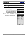
USER MANUAL
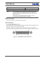
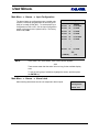
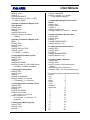
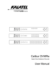
MMX-165C(X)
SIXTEEN-INPUT, FIVE-OUTPUT
COLOR TRIPLEX MATRIX MULTIPLEXER
USER MANUAL
C
D
B
E
{F}
1
2
3
4
5
6
7
8
9
10
11
12
13
14
15
16
ALT
ALT
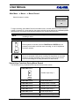
WARNING!
To prevent fire and electric shock, do not expose this product to rain or moisture.
Revision B
0150-0112
USER MANUAL
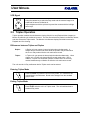
!
The lightning flash with the arrowhead symbol,
within an equilateral triangle, is intended to
alert the user to the presence of uninsulated
"dangerous voltage" within the products
enclosure that maybe of sufficient magnitude
to constitute a risk of electric shock to persons.
The exclamation point, within an equilateral
triangle, is intended to alert the user to the
presence of important operating and maintenance
(servicing) instructions in the literature
accompanying the product.
CAUTION!
To prevent electric shock do not remove cover.
No user serviceable components inside. Refer
servicing to qualified service personnel.
CAUTION! Lithium Battery
Danger of explosion if battery
is incorrectly replaced.
Replace only with the same or
equivalent type recommended
by the manufacturer.
!
ATTENTION
This product contains a lithium battery. This
battery may be recyclable. It may be illegal to
dispose of this battery improperly under local,
state, or federal laws. Check with your local
waste management officials for disposal and
recycling options.
CAUTION!
Electrostatic-Sensitive Device!
Use proper CMOS and MOSFET handing precautions, including approved
grounded wrists straps, etc., to avoid damage to this unit or its internal
components, from electric discharge.
WARNING!
This equipment generates, uses and can radiate radio frequency energy and if not installed and used
in accordance with the instructions in this manual, may cause interference to radio communications. It
has been tested and found to comply with the limits for a Class A computing device pursuant to
subpart J of part 15 of FCC rules which are designed to provide reasonable protection against such
interference when operated in a commercial environment. This equipment has also been tested and
found to comply with the requirements for a CE Class A device and TUV safety standards.
Operation of this equipment in a residential area may cause interference, in which case the user is a
required to take all measures that are necessary, at the user's expense, to correct the interference.
0150-0112
ii
Revision B
USER MANUAL
IMPORTANT INFORMATION
Software and/or firmware is furnished to the purchaser under a license for use on a single system.
Software and/or firmware included with this equipment are the sole proprietary property of, confidential
to, and copyrighted by Kalatel, Corvallis, Oregon, USA. The software/firmware are not to be copied or
disclosed in any manner without the express written consent of Kalatel.
NOTE:
All information and specifications furnished by Kalatel are believed to be
accurate and reliable. But, no responsibility is assumed by Kalatel for
neither its use nor any infringements of rights of third parties that may
result from its use. No license is granted by implication or otherwise under
any patent or patent rights of Kalatel.
The CALIBUR™ brand name and product model numbers are the property of Kalatel.
COPYRIGHT, 2000: The contents of this manual may not be copied or reproduced in any manner or form without the prior written
consent of Kalatel.
Revision B
iii
0150-0112
USER MANUAL
This page intentionally left blank
0150-0112
iv
Revision B
USER MANUAL
Contents
1 INSTALLATION AND GENERAL INFORMATION .............................................. 1-1
1.1
1.2
1.3
1.4
1.5
1.6
1.7
1.8
1.9
1.10
1.11
Product Description.........................................................................................1-1
Features............................................................................................................1-2
Unpacking ........................................................................................................1-3
Installation Environment .................................................................................1-3
Default Passwords...........................................................................................1-3
The Front Panel................................................................................................1-4
The Rear Panel.................................................................................................1-4
Connections .....................................................................................................1-5
Power Supply ...................................................................................................1-9
Power-Up and Testing...................................................................................1-10
Battery Backed-Up Memory for Menu Options............................................1-10
2 OPERATING MODES AND CAPABILITIES .................................................... 2-1
2.1
2.2
2.3
2.4
2.5
2.6
2.7
2.8
2.9
2.10
2.11
2.12
2.13
2.14
Principal Operating Modes .............................................................................2-1
Triplex Operation .............................................................................................2-5
Monitor Displays ..............................................................................................2-7
Salvo Switching .............................................................................................2-12
AutoList and Sequencing..............................................................................2-14
Salvo Switching .............................................................................................2-15
Alarm Operations...........................................................................................2-15
Motion Detection............................................................................................2-18
Freezing ..........................................................................................................2-19
Zooming..........................................................................................................2-19
Daylight Savings Time Change.....................................................................2-20
Macro Functions ............................................................................................2-20
Submacros .....................................................................................................2-21
Front Panel VCR Controls.............................................................................2-21
3 THE MENU SYSTEM ................................................................................. 3-1
3.1
3.2
3.3
Pull-Down Menus .............................................................................................3-3
Pop-Up Menus..................................................................................................3-3
The Available Menus .......................................................................................3-3
4 OPERATOR PROGRAMMING...................................................................... 4-1
4.1
Operator Menu → Field/Frame Display ........................................................4-1
Revision B
v
0150-0112
USER MANUAL
4.2
4.3
4.4
4.5
4.6
4.7
4.8
Operator Menu
Operator Menu
Operator Menu
Operator Menu
Operator Menu
Operator Menu
Operator Menu
→
→
→
→
→
→
→
Sequencing......................................................................4-1
Time/Date Display...........................................................4-3
Title Display.....................................................................4-3
Playback Format .............................................................4-3
Alarm History ..................................................................4-4
Operator Password.........................................................4-4
Normal Record Speed ....................................................4-5
5 INSTALLER PROGRAMMING ...................................................................... 5-1
5.1
5.2
5.3
5.4
5.5
5.6
5.7
5.8
5.9
5.10
5.11
5.12
5.13
5.14
Main Menu
Main Menu
Main Menu
Main Menu
Main Menu
Main Menu
Main Menu
Main Menu
Main Menu
Main Menu
Main Menu
Main Menu
Main Menu
Main Menu
→
→
→
→
→
→
→
→
→
→
→
→
→
→
Time/Date................................................................................5-1
Sequencing.............................................................................5-3
Record ....................................................................................5-4
Alarms.....................................................................................5-6
Macro ....................................................................................5-16
Macro → Edit Submacro ...................................................5-20
Motion Detection..................................................................5-23
Camera Titles .......................................................................5-33
Camera Setup.......................................................................5-34
VCR Setup ............................................................................5-39
Communications..................................................................5-42
Front Panel Lock..................................................................5-43
Factory Settings...................................................................5-44
Passwords ............................................................................5-44
6 SERVICE AND RETURNS ........................................................................... 6-1
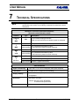
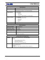
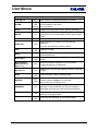
7 TECHNICAL SPECIFICATIONS .................................................................... 7-1
8 RS-232 REMOTE PROTOCOL .................................................................. 8-1
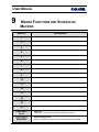
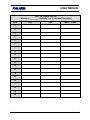
9 MACRO FUNCTIONS AND SCHEDULED MACROS......................................... 9-1
10 STANDARD WARRANTY CONDITIONS ...................................................... 10-1
0150-0112
vi
Revision B
USER MANUAL
1
INSTALLATION AND GENERAL INFORMATION
Table 1-1. Products Described in this Manual
Item
Model Number
Sixteen-Input, Five-Output Color Triplex Matrix Multiplexer
MMX-165C
Expansion Unit
(increases maximum number of inputs to 32)
MMX-325CE
Notes:
Append (X) to the part number if ordering a PAL/CCIR model.
(Otherwise, an NTSC/EIA will be shipped.)
Example: MMX-165C(X)
Key to model numbers:
MMX- 16 5 C (X)
¬
- ® ¯ °
¬
®
¯
°
MMX = Matrix Multiplexer
16 or 32 = Maximum number of cameras (16 for Multiplexer, 32 for Expander)
5 = Number of outputs
C = Color, CE = Color Expander
(X) = PAL/CCIR (if desired)
1.1 Product Description
These multiplexers are video recording and playback systems capable of simultaneously recording
multiple camera signals on a single video cassette recorder (VCR). These units contain dual digital
video processors for continued background recording while viewing multiscreen live or playback
images.
The unit is a single, integrated unit in a 19-inch rack-mountable enclosure. It requires 12 VDC power
from an external AC power supply. The front panel contains all operator control keys and indicators.
Looping auto-terminating video inputs, video outputs, alarm inputs and outputs, and remote control
connectors are on the rear panel.
Revision B
1-1
0150-0112
USER MANUAL
The unit has five monitor outputs, A through E.
Monitor A:
A composite or Y/C SVHS full-screen or multiscreen digital
image display that can be frozen and zoomed.
Monitors B through E:
Full-screen, live, analog output displays.
WARNING!
The unit's primary purpose is to furnish efficient video multiplexing and
multiscreen display. Alarm handling and motion detection are
secondary functions.
The unit should not be the only alarm device on-site. Associated
equipment must comply with national standards.
1.2 Features
•
Quick installation and setup with programmable, easy-to-read on-screen menus
•
AutoList™ simplified sequence programming
•
Operator-programmable macro function keys
•
Scheduling of macros to run automatically at preset times, days, and dates
•
An adjustment for daylight savings time changes
•
Master/slave timekeeping capabilities
•
Remote programming (uploading and downloading) using a PC
•
Remote control using optional keyboard or PC
•
Menu-driven, adjustable camera automatic gain control (AGC)
•
2x digital zoom and digital pan and tilt in Live and Play modes
•
Covert camera settings
•
High quality color definition display (CCIR 601 4:2:2 YUV)
•
Provision for synchronizing the multiplexer with the VCR speeds
•
Multiple alarm inputs and outputs with an alarm history log
•
Both activity and intrusion detection (video motion sensing)
•
Front panel lockout
•
Looping of camera output signals
•
Ability to decode tapes recorded on Dedicated Micros (DM) and Robot multiplexers, allowing
upgrades to obtain the advanced features of the units.
•
Optional enhancements include motorized pan, tilt, and zoom control. Contact your dealer or
distributor for more information on obtaining these enhancements.
0150-0112
1-2
Revision B
USER MANUAL
1.3 Unpacking
Check the package and contents for visible damage. If any components are missing or damaged,
contact the supplier immediately. Do not attempt to use the unit. If, for any reason, they must be
returned, the package and contents must be shipped in the original packing box.
Package Contents
•
Multiplexer unit
•
Alarm I/O interface PCB
•
Power adapter, AC to 12 VDC
•
User Manual
•
Cable for Monitors C through E
•
Cable for Expansion Unit
1.4 Installation Environment
•
Install the multiplexer unit so that the cooling vents are not obstructed.
•
Protect the unit from extreme hot or cold temperatures.
•
Use an uninterruptable AC power supply (UPS).
•
Do not place any weight that exceeds 35 lb. (16 kg) on top of the multiplexer.
The unit's technical specifications appear in Section 7, starting on page 7-1.
1.5 Default Passwords
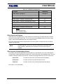
Table 1-2. Passwords
Access
Level
Function
Changeable
by User?
1
Operator
Gives access to
Operator Menu
and view screens
Yes
2
Installer
Gives access to
all menus
Yes
3
4
7
7
3
Installer
Resets
multiplexer to the
factory defaults
No
8
1
1
1
4
Installer
Changes the
menu language
factory defaults
No
5
4
1
5
Password
Revision B
1-3
Default Keys
0150-0112
USER MANUAL
Three levels of password security are provided:
•
Front panel lockout (no access)
•
Operator access level
•
Installer access level
All passwords changed by the user must be numerical. That is, only the number keys can be used
when changing a password.
It is recommended that Password 1 be changed after installation is complete.
As a security measure, store passwords in the Administrator’s secured
files or in a limited-access area.
NOTE:
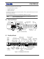
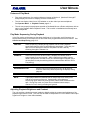
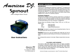
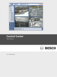
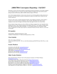
1.6 The Front Panel
Play Key
Camera Select
Keys 1 - 16
Monitors-C, D, and E Keys
Alarm Key
Sequence Key
Live Key
Monitor-A Key
Menu
Key
C
{F}
D
B
E
Zoom Key
Function Key
Monitor-B Key
Record Key
1
2
3
4
5
6
7
8
9
10
11
12
13
14
15
16
ALT
ALT
Freeze Key
Alternate Key
Arrow Keys
Enter Key
Figure 1-1. The Front Panel
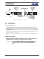
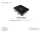
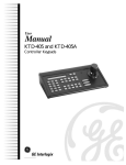
1.7 The Rear Panel
12 Vdc
power,
center
positive
Monitor-A output
VCR input Y/C
Y/C 4-pin
4-pin mini-DIN
Camera BNC
mini-DIN
VCR output Y/C
Inputs 9 - 16
RS-232,
4-pin mini-DIN
Looping
DB-9
connector
VCR output
composite, BNC
Monitor-A output
composite, BNC
RS-232
12V DC
MON C.D.E. 17 - 32
1
2
3
4
5
6
7
8
1
485
2
9
10
11
12
13
14
15
16
B
Camera BNC Monitor-B
Expansion inputs 1 - 8 output, BNC VCR input,
Bus
looping
composite
BNC,
Connector
composite
RS-485 connectors
RJ-45 jacks looping
Alarm, Vext & Accessory
connections DB-25
Figure 1-2. The Multiplexer's Rear Panel
0150-0112
1-4
Revision B
USER MANUAL
Camera BNC
inputs 17 - 24
looping
12Vdc
center
positive
12V DC
17
18
19
20
21
22
23
24
25
C
MON C.D.E. 17 - 32
Monitor-C output,
composite, BNC
Expansion
Bus
Connector
Camera BNC
Inputs 25 - 32
looping
Alarm, Vext & Accessory
connections DB-25
D
26
27
28
29
30
31
32
E
Monitor-E output
composite, BNC
Monitor-D output
composite, BNC
Figure 1-3. The Expansion Unit's Rear Panel
1.8 Connections
Camera Connections
When connecting cameras to the multiplexer, use only 75-ohm video coaxial cables and BNC
connectors. For each camera, there are two BNC jacks. Either jack can receive a camera’s signal.
This signal is looped (directly connected) to the other jack, making the camera’s signal accessible to
other equipment.
When looping, the camera input connectors are auto-terminating. Make sure that there is a 75-ohm
termination at the end of the video line.
If there are fewer than sixteen cameras, the unused camera jacks can be disabled through the menu
system.
VCR Video Connections
As shown in Figure 1-4, the VCR video connectors are video IN and OUT. For a standard
(composite) VCR use 75-ohm coaxial cable and BNC connectors. For a Super VHS (SVHS) VCR,
use 4-pin mini-DIN SVHS connectors, and select SVHS in the VCR Setup menu.
NOTE:
Revision B
SVHS and composite connections can not be used at the same time.
Select either composite or SVHS connections, depending on the VCR
used.
1-5
0150-0112
USER MANUAL
Composite Video VCR Connections
SVHS or Y/C VCR Connections
SVHS
SVHS
Multiplexer
IN
IN
COMP.
SVHS
OUT
OUT
SVHS
SVHS
VCR
Multiplexer
IN
IN
COMP.
SVHS
OUT
OUT
VCR
Figure 1-4. Typical Multiplexer-to-VCR Video Connections (SVHS or Composite)
Consult the VCR manufacturer’s instructions to connect:
This multiplexer jack:
Symbol
:
h
8
Record OUT
Play IN
To this VCR location:
Video IN
Video OUT
VCR Synchronization Connection
The use of the VEXT connection is recommended for time-lapse, high-density, and near-real-time
VCRs.
NOTE:
In this manual, real-time mode is defined as follows:
NTSC/EIA:
PAL/CCIR:
2 hours
3 hours
The VEXT signal simplifies multiplexer operation by synchronizing the multiplexer to the VCR. The
VEXT signal is especially useful with VCRs having dual recording speeds (alarm and normal)
because it makes the multiplexer automatically follow alarms.
Whenever an image is recorded, the VCR sends a VEXT camera switch pulse to the multiplexer. The
multiplexer then transmits the next image to VIDEO IN on the VCR. In this way, the VCR controls the
multiplexer’s recording speed.
If using the VEXT input, the Switch Input option must be enabled in the VCR Setup menu. (The
factory default enables this option.) The VEXT Pulse Edge in the Record menu can be set to trigger
on either the positive-going or negative-going edge.
NOTE:
As a rule, the factory settings should not be changed.
Occasionally, Technical Support recommends different settings. For
example, a user may experience a problem with VEXT or with a particular
model of VCR.
The VEXT input accepts a TTL, field-synchronized, positive or negative pulse.
Consult the VCR manufacturer’s instructions to connect:
0150-0112
1-6
Revision B
USER MANUAL
This multiplexer jack:
To this VCR location:
VEXT input wire (red) and ground wire (black)
The appropriate VCR terminals
NOTE:
Some time-lapse VCRs do not transmit a VEXT signal in real-time mode.
To use such VCRs, select recording speeds (in both the Alarm Record
Speed and Normal Record Speed menus) that generate images at the rate
required by the VCR.
In these cases, be sure to disable VEXT from the menus. Contact
Technical Support if additional assistance is necessary.
Monitor Connections
Use 75-ohm coaxial cable to connect the monitors to the unit.
Alarm Connections
(See also Alarm Operations, page 2-15.)
Wire all alarm, relay, and VEXT connectors to the Alarm I/O PCB supplied. Do not attempt to wire
directly to the connector on the multiplexer back panel.
If the Alarm I/O PCB is lost or missing, contact Kalatel Customer Service for a replacement.
Alternatively, purchase a female DB-25 connector, and make all connections as shown in Table 1-3.
1
13
14
25
Figure 1-5. The Male DB-25 Connector (Rear Panel)
Revision B
1-7
0150-0112
USER MANUAL
Table 1-3. DB-25 Pin Assignments
Function
DB-25 Pins
Alarm inputs 1 through 16
1 through 16
Alarm output 1 (Relay #1), selectable N/O or N/C
Ground connections: Alarms and VEXT inputs
17
18 through 20
Alarm output 1: Relay #1 common ground
21
Alarm output 2: Relay #2 (selectable N/O or N/C)
22
External Alarm silence or acknowledge (active-low)
23
VEXT, VCR synchronization pulse
24
Alarm output 2: Relay #2 common ground
25
NOTE:
N/O = normally open
N/C = normally closed
Alarm Inputs and Outputs
Alarm inputs can be triggered by a relay contact from such devices as smoke detectors, infrared
sensors, pressure pads, and the like. Be sure to connect only resistive loads to the alarm output
relays. Alarms are disabled while the menu system is active.
The alarm output relays can be programmed in the menu system to respond to macro functions,
alarms, and video loss.
NOTE:
Do not exceed 30 V (AC or DC), 500 mA (continuous) on an alarm output
relay's contacts. Specifically, the contacts must not be used at AC line
voltages.
Silencing and Acknowledging Alarms
The silence-and-acknowledge function silences alarms by grounding pin 23 to pins 18 through 20.
This operation merely deactivates the alarm LED, alarm output relay, and keyboard buzzer. But, the
condition creating the alarm may still exist. Alarms can be programmed in any one of three ways:
Latched On:
An alarm is active until it is silenced and acknowledged.
Transparent:
An alarm is active only while the input is active.
Timed Out:
An alarm is active until a menu-programmed time expires.
See Table 5-1 for more details.
0150-0112
1-8
Revision B
USER MANUAL
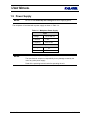
1.9 Power Supply
NOTES:
Be sure to read Power-Up and Testing below before applying power.
The multiplexer is furnished with a power supply as shown in Table 1-4.
Table 1-4. Multiplexer Power Supply
Input
Voltage
110 to 240 VAC
Tolerance
± 10%
Frequency
50 to 60 Hz
Output
NOTES:
Voltage
12 VDC
Power
25 W
Do not use any other power supply.
The manufacturer accepts no responsibility for any damage caused by the
use of any other power supply.
Read all the operating instructions before operating the unit.
Revision B
1-9
0150-0112
USER MANUAL
1.10
Power-Up and Testing
Once the installation is complete, turn on the power in the order indicated below. The unit starts by
displaying the software version on Monitor A. This is followed by a multiscreen display.
If any settings in the Menu system have been changed, those settings are stored while the power is
off and are still in effect.
1. Energize the monitors and all the cameras.
2. After doing so, energize the unit's 12 VDC power supply.
3. In Live mode, select full-screen display for each camera and check the picture quality. If the
quality is poor, check:
- The BNC connections
- Loop-through terminations
- Video levels of incoming signals and the possibility of ground loops.
Record/Play Quality
Record for at least three minutes at normal VCR speed (2-hour for NTSC/EIA, 3-hour for PAL/CCIR).
Then play back the recording, selecting each camera for full-screen display in turn. Check the
playback picture quality. Be sure to check the VCR’s tracking adjustment. (For advice on setting up
the cameras, consult the camera’s installation instructions.)
Adjusting Playback Brightness and Contrast
The unit provides a simple front-panel digital adjustment to set the contrast and brightness of the
playback signal from the VCR. (This can also be used to compensate for a VCR whose video output
signal level is higher or lower than standard.)
Test the VCR VEXT switch pulse connection to the multiplexer by setting the unit to Record mode to
start VCR recording. Observe that REXT (Record + EXTernal) appears in the upper right corner
while recording. Play back the recording, and observe that PEXT (Play + EXTernal) appears in the
upper right corner of the monitor.
See Adjusting Playback Brightness and Contrast, page 2-4.
1.11 Battery Backed-Up Memory for Menu Options
Menu selections are saved to battery-backed-up memory. In general, the battery has a five-year
shelf life, and holds memory even if the unit is off for several months.
CAUTION:
All stored information is lost if the battery is removed.
Moreover, when the system is re-energized, it reverts to factory defaults.
0150-0112
1-10
Revision B
USER MANUAL
2
OPERATING MODES AND CAPABILITIES
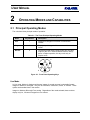
2.1 Principal Operating Modes
The units have three principal modes of operation:
Table 2-1. The Three Principal Operating Modes
Mode
Key Number
Description
Live
1
Displays live images in full-screen or multiscreen
formats
Play
2
Displays taped images in full-screen or multiscreen
format
Record
3
Combines several camera input signals into one video
output for the VCR. Because Record mode is always
active in Duplex operation, this key works only on
Simplex units.
1
2
3
Figure 2-1. Front Panel Operating Keys
Live Mode
In Live mode, Monitor A displays multiscreen images of several cameras in selectable formats.
Images on Monitor A are digital. They can be full-screen, multiscreen, frozen, or zoomed. These
options are described later in this section.
Images on Monitors B through E are analog. Regardless of the mode selected, these monitors
display only live, full-screen images from one camera.
Revision B
2-1
0150-0112
USER MANUAL
Options Available on Monitor A Output in Live Mode
•
Multiscreen displays from picture-in-picture (PIP) to 4x4 display of sixteen cameras (depending
on the model). If a multiscreen does not include all cameras, the system can automatically
sequence the remaining cameras into the last (bottom right) cameo.
•
A full-screen display of any camera.
•
A customizable sequenced display of full-screen cameras.
•
2x electronic zoom with the ability to pan and tilt across the entire image smoothly.
•
Full-screen or individual cameo freezing capabilities.
Automatic Multiscreen Format Memory
2
The user can switch from a multiscreen to full-screen camera image by
pressing the camera number key.
Subsequently pressing the MULTISCREEN key (Monitor A Key in
Figure 1-1) restores multiscreen display.
Record Mode
Time division multiplexing (TDM) combines several camera input signals into one video output signal.
Single fields are digitally captured from each of the video-input channels, and then stacked
consecutively to form a continuous video signal of time-sliced camera fields. (See the example
below.)
Captured fields are controlled by the Record List, which the system modifies in case of alarms,
motion detection, or video loss. A single VCR can then record the multiplexed video fields.
NOTE:
Time base correction is performed during digital capture. As a result,
cameras do not require synchronization.
For example, three multiplexed inputs are recorded like this:
-
A1
A2
A3
A4
A5
A6
A7
-
B6
B7
-
C6
C7
-
C6
A7
-
Camera A video fields
-
B1
B2
B3
B4
B5
Camera B video fields
-
C1
C2
C3
C4
C5
Camera C video fields
-
A1
B2
C3
A4
B5
Multiplexed video stream to VCR
0150-0112
2-2
Revision B
USER MANUAL
On MMX units, Record mode is always active. It is not necessary to press the RECORD key.
In Live or Play mode, any Monitor A multiscreen function can be selected while recording. (See
Multiscreen Formats on Monitor A, page 2-8.) When the unit and VCR are in Play mode, images
on Monitor A come from the VCR tape. If the VCR is not in Play mode, the images on Monitor A
come from the VCR output of the unit, not recorded images.
Record Speed Symbol on Monitor A
In Record mode, the unit indicates the recording speed on Monitor A. It uses the same time-format
generally used by time-lapse VCRs. For example, R024 appears for a unit recording in 24-hour
mode. (If the VCR VEXT input is active, then REXT appears.)
Outputs from Monitors B through E
These monitors always display analog live full-screen images of camera output signals, regardless of
its operating mode.
Alarm Displays in Record Mode
Alarm displays conform to the Live or Play modes of operation.
Play Mode
Playback of Multiplexed Recordings
Multiplexed recordings are time-stamped video fields received from the VCR. The embedded digital
data packets are decoded, and all the associated status information, titles, time and date of recording
(as well as the alarm or video loss status of the camera) are re-constructed and displayed with
on-screen text during playback.
During playback, the user selects one of several screen formats, the fields to be displayed (or
skipped), and the camera positions in multiscreen.
The difference between on-screen displays and VCR text displays recorded as part of video is this:
on-screen display has clear, legible status and titles during playback.
In Play mode, the unit selects a multiscreen that displays all possible recorded images on Monitor A.
The appearance of the letter P on-screen indicates that the unit is in Play mode. The speed at which
the data was recorded appears after the P (as in P002 or P024). If the recording was made using the
camera switch input (VEXT), the mode and speed are displayed as PEXT. The time and date appear
on-screen during Play mode. This is the time recorded on the tape, not the current system time. If
video loss occurred while recording, a V appears in the corresponding camera cameo (VDL if
full-screen display has been selected).
Revision B
2-3
0150-0112
USER MANUAL
Features of Play Mode
•
Play mode cancels any Live mode multiscreen images on Monitor A. (Monitors B through E
always display full-screen live displays, and are not affected.)
•
The unit can display video from a VCR whether or not the video input was multiplexed.
See Operator Menu → Playback Format, page 4-3.
•
The unit can properly interpret tapes encoded on Dedicated Micros or Robot multiplexers with an
option in the Operator Menu Playback Format. This is useful in installations that already have
other multiplexers.
Play Mode Sequencing During Playback
In the Play mode, multiscreens use the same dwell time as in Live mode, and full screens are
sequenced according to the Sequence List and dwell times programmed with AutoList feature. See
AutoList and Sequencing, page 2-13.
CAUTION:
When sequencing a display during playback, set the VCR’s playback
speed faster than the dwell of cameras being played back. In this way, the
tape runs more slowly than does the Sequence List that is actively
switching through the Camera List.
EXAMPLE:
If the VCR is set in the 48-hour mode, it displays the camera fields at
approximately 5-second intervals. While a tape having multiple camera
fields is played back, the fields for any one camera might not appear (since
the sequence list may be switching between cameras faster than the VCR’s
Play setting).
RECOMMENDATION:
NOTE:
Set the VCR to its normal speed (2-hour for NTSC/EIA,
3-hour for PAL/CCIR) when sequencing the displays during
playback.
Tapes played back from different sites or setups may have nothing to do
with the current setup of the unit. Consequently, the multiscreen
sequencing option works only through those camera fields recorded on the
tape. During Play mode, any video loss or disabled camera setups
detected in Live or during recording are ignored.
Adjusting Playback Brightness and Contrast
The unit provides a simple front-panel method to digitally adjust the contrast and brightness of the
playback signal from the VCR. (This can also be used to compensate for a VCR whose video output
signal level is higher or lower than standard.)
0150-0112
2-4
Revision B
USER MANUAL
VCR Signal
2
Using the camera keys, select the Play mode and the camera image to be
enhanced full-screen on Monitor A.
Adjust brightness with the up/down keys and the contrast with the left/right
arrow keys.
2.2 Triplex Operation
Triplex operation enables the simultaneous viewing of both Live and Playback video images (on
Monitor A) while the unit continues to record. The user first selects Play mode in multiscreen format,
and then selects the Triplex mode. The Monitor A multiscreen display is divided into areas for
Playback and Live viewing.
Differences between Triplex and Duplex
Duplex:
A Duplex unit can operate in two principal modes simultaneously. It
always has the record mode active while the operator may choose either
the Live or Play mode while the unit continues to record.
Triplex:
A Triplex unit can operate in three principal modes simultaneously. Like a
duplex unit, a Triplex unit always has the record mode active. But, in
addition, a Triplex unit allows the operator to select both Live and Play
modes simultaneously on Monitor A while the unit continues to record.
The unit must be in Play multiscreen before Triplex mode can be entered.
Entering Triplex Mode
Press the PLAY key while the unit is in Play mode. If in full-screen, the
unit switches to a multiscreen. Border color changes from the standard
gray to white.
Exiting Triplex Mode
Press PLAY while the unit is in Triplex mode. The unit switches back to
standard Play mode.
Revision B
2-5
0150-0112
USER MANUAL
The order in which the Triplex multiscreens appear each time the MULTISCREEN key is pressed
and the Play/Live split is shown below:
Top 8: Play
Bottom 8:
Top 2: Play
Bottom 8:
Top 3: Play
Bottom 6:
Top 2: Play
Bottom 2:
Live
Live
Live
Live
Full screen:
Play
PIP: Live
Sequencing in Triplex Live Cameos
Pressing the SEQUENCE key while in multiscreen sequences all Live
undisplayed cameras in the lower right cameo (at the multiscreen dwell
time).
No menu setup is required.
Note that there is no programmable sequence list for multiscreens.
NOTES:
There is no programmable sequence list for multiscreens.
No playback cameo sequencing is supported in Triplex mode.
Triplex and Full-Screen Displays
1
Pressing a full-screen key selection shows the selected camera image in
Play mode, but not Live mode.
Subsequently pressing the MULTISCREEN key returns the unit to Triplex
mode.
Camera Position Selection for Active Cameos
Triplex supports customary position and display selection with active cameos.
0150-0112
2-6
Revision B
USER MANUAL
2.3 Monitor Displays
Changing Positions and Colors of Titles and Date/Time
Titles can be displayed as black, gray, or white characters. This feature is selectable for each camera
during either Live or Play modes.
Change Position and Color
Select a full-screen view of that camera on Monitor A, and then press
ENTER several times to toggle the title position and color. Select from
one of seven options for each camera.
Pressing the ENTER key initiates the following cycle:
1.
Top, black.
2.
Top, gray.
3.
Top, white.
4.
Bottom, black.
5.
Bottom, gray.
6.
Bottom, white.
7.
Do not display this camera title.
8.
(Repeats from top).
The color of the on-screen time and date on Monitor A can be changed to black, gray, or white
To change time and date color on Monitor A:
1. Select a camera for full-screen display.
2. Toggle its position and color as described above.
Each time the cycle is completed for the camera, the color of the time and date changes. The
position of the time and date can not be changed.
Once the color has been selected, the user can toggle the camera's title position, as well as its display
color.
Can Color be Changed?
Revision B
Can Position be Changed?
Monitor
Title
Time and Date
Title
Time and Date
A
Yes
Yes
Yes
No
B through E
No
No
No
No
2-7
0150-0112
USER MANUAL
Multiscreen Formats on Monitor A
Monitor A formats are Full-Screen, Multiscreen, or Active Cameo.
Multiscreen Order of Display
Select different multiscreen displays by pressing the MULTISCREEN key
(Monitor A Key in Figure 1-1) on the front panel.
During start-up, the unit selects a multiscreen display on Monitor A that
allows simultaneous viewing of all cameras recorded.
The multiscreen order of display changes and repeats each time the key is pressed:
16-WAY
13-WAY
10-WAY
9-WAY
7-WAY
QUAD
PIP
4x4
1x12 •
2x8
3x3
3x4 •
2x2
1 in 1
•
Not available in Play mode on any units.
NOTES:
The best resolution for multiple camera images is furnished by quad
display. Quad display is selected with the MULTISCREEN key (16-Way
Key in Figure 1-1). Use the Active Cameo mode to select the cameras.
Display formats are operating parameters, not menu selections. They are
saved in volatile memory, not in battery backed-up memory.
Automatic Multiscreen Format Memory
2
The user can switch from a multiscreen to full-screen camera image by
pressing the camera number key.
Subsequently pressing the MULTISCREEN key (Monitor A Key in
Figure 1-1) restores the previous multiscreen display.
Changing Cameras in Multiscreen Displays
Any camera can be displayed in any position in the unit’s multiscreen displays. The default
multiscreen displays show the cameras in ascending order. In the Live mode, the user can display
one camera in more than one position, while in Play mode each camera can be displayed only once
on each multiscreen. To select any camera for display in any cameo in a multiscreen, the unit uses
active cameos (see below).
0150-0112
2-8
Revision B
USER MANUAL
Active Cameo Mode
To select different cameras in a multiscreen display, the unit uses active cameos.
To select different cameras in a multiscreen display, the unit uses active
cameos.
Press the ENTER key while displaying any multiscreen. The top left
cameo is the initial active cameo. The active cameo is indicated by
flashing its camera number and title.
The Active Cameo mode persists for about 15 seconds after the last key is
pressed, or until the ENTER key is pressed again to exit the mode. Active
Cameo mode is canceled if a new multiscreen display is selected, or if
there is switching between Live and Play modes.
Working with an Active Cameo
In a multiscreen display, the user can freeze or unfreeze a cameo. This is useful when an event must
be frozen for further investigation or for review by a supervisor, but the other cameras must be
monitored.
Automatic Camera Location Memory
The user can set up camera numbers and locations to be displayed in a particular multiscreen
display. Each time that particular multiscreen is selected, the setup appears. The unit saves this
information in volatile memory.
Table 2-2. Key Functions During Active Cameo Mode
Key
1
2
Description
Function
Arrow
Moves the active cameo around the multiscreen.
Camera
(1 through 16)
Selects a camera to be displayed in the active
cameo. Once the desired camera is selected, the
active cameo advances to the next logical cameo
on the right.
FREEZE
Freezes the active cameo.
Switches to a full-screen display of the active
cameo.
ZOOM cancels Active Cameo mode.
ZOOM
Revision B
Notice that if the ZOOM key is pressed with no
active cameo selected, then the display switches
full-screen to the camera displayed in the cameo
last selected.
2-9
0150-0112
USER MANUAL
Sequencing in Cameos
In multiscreen displays, pressing the SEQUENCE key advances all
remaining cameras in the lower right cameo. (No menu setup is required.
The cameo sequence list can not be edited.)
The dwell time is the multiscreen dwell time selected in the menus. The
default value is 3 seconds.
Picture-in-Picture Display
The PIP display on Monitor A can be displayed in one of three sizes, and one of two positions. Select
the PIP multiscreen for display on Monitor A.
PIP Size and Position
Position: Use the up/down arrow keys. The PIP can be placed at the
upper left or lower right of the display.
Size: The left arrow key makes the image smaller. The right arrow key
makes it larger. The sizes can be 1/4, 1/9, or 1/16 of full-screen.
Full-Screen Displays on Monitor A
Full-Screen Display
1
Select a full-screen display of any camera on Monitor A by pressing the
camera number key.
Full-Screen Sequence List and Dwell Time
Independent sequences operate on the monitors. See AutoList and Sequencing, page 2-13.
Full-Screen Sequencing on Monitor A
Select any full-screen display by pressing the camera number key, and
then the SEQUENCE key.
Canceling Full-Screen Sequencing on Monitor A
Press either the SEQUENCE key (again), any camera number key, or any
multiscreen key.
3
Adjusting the Resolution
The resolution of digital full-screen displays can be toggled between frame display or field display.
The lower resolution field display can result in less flickering on some high contrast camera scenes.
Frame resolution is fully interlaced, and provides higher resolution. See Operator Menu →
Field/Frame Display, page 4-1.
0150-0112
2-10
Revision B
USER MANUAL
NOTE:
This is a global system setting, and all camera displays are changed.
Displays on Monitors B through E
These are full-screen and analog, displaying only Live images (regardless of the mode selected). A
sequenced or fixed display of any one camera can be selected on Monitors B through E.
CAUTION:
The time, date, alarm, video loss messages, titles, and all on-screen data
on Monitors B through E are related to current, live data, and must not be
confused with the playback data that might be displayed on Monitor A.
Independent Sequence List and Dwell Times
Independent full-screen sequences may operate on Monitors A through E. See AutoList and
Sequencing, page 2-13.
Operating on Monitors B through E
B
Press the MONITOR key first. The LED lights until the same MONITOR
key is pressed again. While the LED remains on, the camera keys and the
SEQUENCE key operate on the selected monitor, and not on Monitor A.
Selecting a Camera Full-Screen on Monitors B through E
1
While the monitor's LED is on, press a camera number key.
Starting Sequencing on Monitors B through E
While the monitor's LED is on, press the SEQUENCE key.
Canceling Sequencing on Monitors B through E
To select a fixed display on Monitors B through E:
While the monitor's LED is on, press either the SEQUENCE key or a
camera number key.
Revision B
2-11
0150-0112
USER MANUAL
2.4 Salvo Switching
Salvo Switching is a feature that enables Monitors B through E to sequence simultaneously among
groups of cameras.
This option is enabled through the menu system. Once enabled, it can be activated (or deactivated)
only by means of a password.
Activation of Salvo Switching
When Salvo Switching is activated, Monitors B through E sequence simultaneously, according to the
parameters programmed in the menus. With Salvo Switching enabled, Salvo Switching is activated
as follows:
1. Select a monitor (B through E) by pressing its button.
2. Press the SEQUENCE button.
3. Monitors B through E then begin simultaneous sequencing.
Deactivation of Salvo Switching
When Salvo Switching is deactivated, only the selected monitors can sequence. With Salvo
Switching enabled, Salvo Switching is deactivated as follows:
1. Select a monitor (B through E) by pressing its button.
2. Press the SEQUENCE button.
3. Monitors B through E then stop sequencing.
0150-0112
2-12
Revision B
USER MANUAL
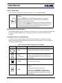
Table 2-3. On-Screen Messages
Appearance on Screen
Situation
Full-Screen
Multiscreen
Alarm
The abbreviation ALM
in each camera in
alarm.
The letter A in each
cameo in alarm.
Frozen
A flashing FRZ symbol
in each frozen camera.
A flashing S
symbol in each
frozen cameo.
Video Loss
(Live or Play mode)
The abbreviation VDL
when the affected
camera is displayed.
The letter V in each
affected cameo.
Motion Detection
When enabled in
programming, the
letter M appears in
each camera scene
when motion is
detected. It remains
on each active camera
display for at least two
seconds after the
motion has ceased.
Both
Record Speed
R### (such as R024 to
indicate 24-hour
mode).
(If the VCR VEXT
input is active, then
REXT appears.)
A
Playback
P### (such as P024 to
indicate 24-hour
mode).
(If the recording was
made using the
camera switch input,
VEXT, then PEXT
appears.)
Zoom
ZOOM (The ZOOM key's LED lights. The
ZOOM key must be pressed again to return to
normal.)
Macro execution
Fn followed by the macro number.
Example: Fn 02.
AutoList program (if active)
PGM
Revision B
2-13
Appears on
Monitor:
Full-Screen:
Both
Multiscreen: A
0150-0112
USER MANUAL
Table 2-3 On-Screen Messages
Appearance on Screen
Situation
Full-Screen
A camera was not included in
the Record List during
recording.
Multiscreen
Appears on
Monitor:
N/A
(A warning message that appears only during
playback on Monitor A.)
A camera was disabled during
recording.
The images for a camera on
tape have been corrupted, and
can not be decoded on
playback.
The VCR Play speed is very
slow.
During playback, a camera was
not detected on tape for several
consecutive cycles.
2.5 AutoList and Sequencing
The AutoList function lets the user change the default camera sequence and dwell settings, and can
accommodate up to 32 cameras. The same camera can appear more than once in the sequence.
The default dwell time is 3 seconds, and is set from the Operator or Main Menu.
Full-Screen and Multiscreen Dwell Time
In the Sequence menu, the user can select the dwell time for both full-screen and multiscreen.
Setting Up an AutoList Custom Sequence List on the Monitors
.
Press the ALARM and SEQUENCE keys simultaneously to record an
AutoList sequence in full-screen mode (Live or Play). An on-screen
indicator (PGM) appears on Monitor A.
.
Press the camera keys in the sequence. After pressing a camera number
key, pause for a time interval equaling the dwell time desired for that
camera.
.
Then press the next camera key, and so on.
.
Press the SEQUENCE key to end AutoList recording.
Pressing any key other than a valid camera key or the SEQUENCE key during recording voids the
AutoList. To return to the factory default settings (all cameras included in the sequence list with a
fixed dwell time), go to the Sequence menu, and change the dwell time.
NOTE:
0150-0112
The AutoList is erased whenever the Fullscreen Dwell setting is changed in
the Sequence menu. All monitor sequences change to the new Fullscreen
Dwell setting, with all cameras consecutively sequenced.
2-14
Revision B
USER MANUAL
2.6 Salvo Switching
This feature must be programmed and activated from the menu system. See Section 0.
2.7 Alarm Operations
The system is equipped with one alarm input per camera, each normally associated with its live video
input. An alarm input displays on-screen warnings on the monitors, flashes front panel LED, and
sounds an internal buzzer. Record List priority automatically changes.
Two internal isolated alarm output relays are provided. Both can be activated by any alarm input,
manually or by the built-in motion detection sensors. Each input alarm can be programmed to
activate either of the relays, both, or none.
During alarms, the unit can automatically record alarmed cameras more frequently. Macro functions
can be activated by an alarm input, and execute several pre-recorded keystrokes automatically. Any
alarm input can be enabled or disabled. See Main Menu → Alarms, page 5-6.
Programmed and Manual Alarm Capabilities
Alarms can be programmed to:
•
Activate either one or both of the Alarm Output Relays.
•
Latch until reset, timed-out (latched for a preset time), operate as transparent, and follow the
status of the alarm input, either in-alarm or normal.
•
Activate a pre-programmed macro.
•
Activate the internal buzzer.
Manual Alarm Activation (Simulated Alarm): Simultaneously pressing
the ALARM key and a CAMERA number key simulates an actual alarm.
1
Silencing and Acknowledging Alarms: To silence and acknowledge all
displayed alarms, press only the ALARM key.
The pre-programmed alarm responses run automatically when an alarm is manually initiated.
Programmed parameters control the alarm, camera recording, latching mode, buzzer setting, and
relays.
Alarm Displays in Live and Record Modes
During alarms in Live mode, Monitor A switches to a pre-programmed, multi-screen alarm display
(assuming that the programmer has not specified full-screen alarm displays). Depending on how the
alarm is programmed, a monitor other than A is simultaneously switched full-screen to the camera in
alarm.
Revision B
2-15
0150-0112
USER MANUAL
NOTES:
The custom alarm screens on Monitor A are displayed only while the alarm
is active. Once the alarm times out or is cleared, the display reverts to the
screen displayed before the alarm. As a result, it is very important to
select the best alarm-latching mode for alarm displays.
If the user changes the screen format while an alarm is active, then the
unit continues to display the selection after the alarm clears. It does not
revert to the pre-alarm screen display.
Monitor A Multi-Screen Display During Alarms
During alarms in Live mode, Monitor A shows a customized display indicating the camera in alarm
together with three associated cameras. The programmer can also select whether or not the system
should freeze the camera in alarm when the alarm input is received.
Depending on the number of simultaneous alarm inputs, the customized alarm displays are selected
by the multiplexer to show all cameras in alarm, as well as plus associated cameras. The custom
screens are automatic for up to three simultaneous alarms. The displays are as follows.
First Alarm
Second Alarm
Third Alarm
Cameras in alarm
Top left cameo
Top two cameos
Top three cameos
Associated cameras
The remaining
cameos
Three of the four
cameos below each
top cameo
The remaining
cameos
Displays for More than Three Simultaneous Alarms
If more than three alarms are active at the same time, the unit selects a display format that shows all
the cameras in alarm. Associated cameras are not selected for display, and alarms are not frozen.
This is usually a 9-way display (unless more than nine cameras are in alarm at the same time). As
each new alarm is received, the unit adjusts the display.
Full-Screen Displays on Monitors B through E During Alarms
Salvo Switching Disabled
During alarms, the monitor (B through E) designated as Aux Monitor in the menu switches to a
full-screen display of the camera in alarm. The other monitors continue to display their current
cameras and not change due to alarm.
If multiple alarms are active, the designated Aux Monitor sequences among the alarm cameras at a
fixed 1-second dwell, which is not programmable. Monitors B through E cannot freeze images on
alarm.
Salvo Switching Enabled
During alarms, the Aux Monitor setting has no effect. Monitors B through E switches to a full-screen
display of the cameras programmed as the Input Group in the Alarm Action Setup menu.
For example, if input alarm 01 is activated, Group 01 cameras display on Monitors B through E.
0150-0112
2-16
Revision B
USER MANUAL
If multiple alarms are active, Monitors B through E sequence between the alarm camera Groups at a
fixed 1-second dwell. This dwell is not programmable. Monitors B through E cannot freeze images
on alarm.
NOTE:
The Monitors B through E screens do not revert to original fixed displays
after the alarm is cleared. They continue to display the last alarm camera.
But, if sequencing was active on Monitors B through E before the alarm,
then Monitors B through E continue to sequence after the alarm is cleared.
If the user changes the screen format while an alarm is active, then the unit continues to display the
selection after the alarm clears. It does not revert to the pre-alarm screen display.
Full-Screen Alarm
If the programmer does not install Monitors B through E and relies solely on Monitor A for all system
information, a full-screen alarm display on Monitor A may be preferred to the custom multiscreen
displays.
In this case, the programmer can select a menu option in the Alarms menu that makes Monitor A:
•
Switch to a full-screen display of the camera in alarm.
•
Sequence full-screen between multiple alarms (as Monitors B through E normally do).
The custom alarm screens do not appear. (This is a global setting for all cameras).
If the option was selected in the Alarm Action menu, a single full-screen alarm is not frozen.
Alarm LED and Internal Buzzer in Live Mode
An alarm LED is provided on the front panel above the ALARM key. This LED flashes until:
•
A Live alarm is silenced or acknowledged (latched and timed-out alarms).
•
The alarm times out or returns to normal status (timed-out and transparent alarms).
An internal buzzer sounds while the alarm condition exists. This buzzer can be disabled only through
the Installer menu.
If the Monitor A screen format is changed while an alarm is active, the unit continues to display the
selection after the alarm is silenced and acknowledged. It does not revert to the pre-alarm screen
display.
The Monitor B screen does not revert to its original fixed display after the alarm is silenced and
acknowledged. It continues to display the last alarm camera. But, if sequencing was active on
Monitor B before the alarm, then Monitor B continues to sequence after the alarm is silenced and
acknowledged.
Revision B
2-17
0150-0112
USER MANUAL
Alarm Displays in Play Mode
Recorded Alarms
In the Play mode, Monitor A does not provide custom alarm displays based on recorded alarm status.
Rather, it displays the playback images from the VCR according to the selected formats. It displays
the normal A alarm indicator only if a camera was in alarm at the time that a recording was made.
CAUTION:
The Monitor B time, date, alarm, video loss, titles, and all on-screen data
are related to current, live data, and must not be confused with the
playback data that might be displayed on Monitor A.
If the camera is not being displayed, no on-screen indication of an alarm appears. When searching
during playback for cameras in alarm, make sure all cameras on tape are displayed using a
16-channel multiscreen.
Monitor B during Play Mode
Monitor B continues to display live images according to any programmed parameters. If a Live
alarm occurs during Play mode, Monitor B switches to the camera in alarm. It sequences at a
1-second dwell time for multiple cameras in alarm. After the alarm is canceled, Monitor B continues
to display the camera on the screen at the time the alarm was canceled (or else continues to
sequence if sequencing was enabled).
Alarm Symbols
Multiscreen Displays:
The letter A appears on-screen in each cameo in alarm.
Full-Screen Displays:
The abbreviation ALM appears on-screen in each camera
in alarm.
Alarm History and Log
An alarm history is kept in a cyclic buffer. History data, including camera number and time and date,
is kept in memory. The most recent 100 alarm events can be viewed on-screen by selecting Alarm
History from the Operator Menu.
A table appears, allowing the user to browse forward and backwards. Each event links the time of
occurrence with an alarm-input number. The RS-232 port allows uploading the alarm history to a PC
or similar remote control device.
2.8 Motion Detection
These units offer complete motion detection including built-in false alarm rejection, sensitivity
settings, and size discrimination per camera. Motion detection is used to adjust the rate at which
cameras are recorded (Activity Detection), and as an intrusion alarm sensor to trigger an alarm input
(Intrusion Detection). The ability to reduce false motion alarms is a major difference between
intrusion detection and activity detection.
0150-0112
2-18
Revision B
USER MANUAL
Activity Detection
Activity detection looks for luminance changes in selected areas of the screen. Changes above a set
threshold are interpreted as activity. Changes in light and camera vibration may be falsely interpreted
as activity. This type of motion detection is offered by most multiplexers, and is adequate to detect
activity in a scene when false detection is not important. Typically, activity detection is used in
crowded areas, where motion is not the result of intruders, and where movement is normal and
expected.
Intrusion Detection
Intrusion detection looks for unusual movement in the scene. If any is found, an alarm is generated.
This feature is used to monitor areas where no movement is allowed or expected. When movement
is found in such an area, an intruder has probably caused it. It is important that intrusion detectors
not cause false alarms resulting from light changes, random reflections, or camera vibration.
If an alarm input is activated by one of the unit’s internal motion detector channels, the system does
not differentiate between an input from another alarm sensor, and the input activated by the link from
the internal motion detection.
Symbols
When enabled in programming, the letter M appears in each camera scene where motion is detected.
This M remains on each active camera display for at least two seconds after the motion has ceased.
2.9 Freezing
The FREEZE key is used to freeze and unfreeze displays. In the Live and
Play modes, use this key to freeze displays on Monitor A. Frozen
full-screen images can be zoomed (see below).
The freeze is not available on Monitors B through E.
Working with an Active Cameo
In a multiscreen display, the user can freeze or unfreeze a cameo. This is useful when an event must
be frozen for further investigation or for review by a supervisor, but the other cameras must be
monitored. See Live Mode, page 2-1.
Symbols
A flashing on-screen display of the symbol S in each frozen cameo (FRZ on full-screen displays).
The PAUSE key must be pressed again to unfreeze the display. Frozen images can be zoomed.
Most other keys are disabled while freezing is in effect.
NOTE:
If the FREEZE key is pressed in a multiscreen display, the entire
multiscreen is frozen.
2.10 Zooming
The unit provides a digital 2x zoom for full-screen displays on Monitor A in the Live and Play modes.
This feature is not available on Monitors B through E.
Revision B
2-19
0150-0112
USER MANUAL
Zooming an Image
First select a full-screen display on Monitor A, and then press the ZOOM
key. Zooming works with both frozen and non-frozen displays. A zoomed
image can be frozen.
Electronic Pan and Tilt
Use the arrow keys to pan and tilt to different sections of zoomed displays
on Monitor A.
Symbols
•
The word ZOOM appears on-screen. In addition, the ZOOM key's LED lights
•
The ZOOM key must be pressed again to return to normal.
•
Most other keys are disabled while zooming is in effect.
NOTE:
If the ZOOM key is pressed in a multiscreen display, the image in the last
active cameo selected expands to full-screen.
2.11 Daylight Savings Time Change
The unit provides a simple way to adjust for daylight savings time, using the FUNCTION and
SEQUENCE keys.
{F}
To adjust the clock by one hour for daylight savings time changes, press
FUNCTION, and then SEQUENCE.
In April, time adjusts forward one hour. In October, time adjusts back one hour.
This function can be used only once in each period. For example, if the FUNCTION and SEQUENCE
keys are pressed during April, an hour is added to the time. If these keys are pressed again, the
command is ignored until October.
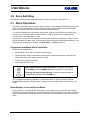
2.12 Macro Functions
Macro Functions enable the recording of frequently used key sequences and menu setups. These
sequences run in two-keystroke settings.
Depending on the number of cameras and the model type, up to ten or sixteen macros, each having
up to 32 keystrokes can be programmed.
Macros can be programmed to start at a fixed day and time. Scheduled events can be started on a
preset day and time or at the same time every day. Any macro can be started by each of the twenty
scheduled events, and a macro can be started by more than one event.
For easy reference, tables are provided in the back of this manual to record scheduled events and
macros.
0150-0112
2-20
Revision B
USER MANUAL
Running a Macro
{F}
1
A macro can be manually activated by pressing the FUNCTION key,
followed by the CAMERA key that corresponds to the macro number (1
through 16). A macro can be canceled with the FUNCTION key.
While a macro is playing, the letter F and the macro number appear.
2.13 Submacros
Macros generate RS-232 commands that can communicate with other RS-232 devices. Submacros
are programmed within a macro.
A submacro transmits a programmed string of bytes from the RS-232 port of the multiplexer. Its
purpose is to communicate with other RS-232 devices, such as VCRs. This permits RS-232 control
of VCR functions.
The use of submacros increases the flexibility of the multiplexer by enabling the transmission of an
RS-232 message when a macro is activated. Macros can be timed, linked to alarms, or manually
activated from the front panel or keyboard. A submacro programmed into a macro runs along with
the keystrokes recorded in a stored macro.
2.14 Front Panel VCR Controls
The unit can control the following VCR functions through the front panel keypad.
Play
Frame Advance
Record
Frame Reverse
Rewind
Stop
Fast Forward
Freeze
To make these control functions accessible, the multiplexer must be connected to the VCR through
the RS-232 port. The installer must program this operation.
To Control the VCR Functions
First, activate the Alternate mode by pressing the red ALT key on the
keypad.
ALT
The ALT key is a toggle on/off key. A red LED above the ALT key lights
when the mode is active. When the mode is active, the associated VCR
function keys are operational.
The VCR function keys are identified with red symbols for the action they
perform while in this mode.
Revision B
2-21
0150-0112
USER MANUAL
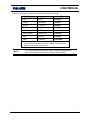
The VCR functions keys activated in the Alternate mode are as follows:
Key
Play
PLAY
VCR PLAY
Record
RECORD
VCR REC
Rewind
Left Arrow
VCR REW
Fast forward
Right Arrow
VCR FF
Frame advance
Up Arrow
VCR F ADV
Frame reverse
Down Arrow
VCR F REV
Stop
ENTER
VCR STOP
Pause
FREEZE
VCR PAUSE
†
NOTE:
0150-0112
Indicator †
Function
In the Alternate mode, on-screen indicators appear for a few
seconds after the selected function is initiated. These indicators
appear in any monitor display mode.
To turn off the Alternate mode and return to normal keypad operations
after performing the VCR functions, press the ALT key again.
2-22
Revision B
USER MANUAL
3
THE MENU SYSTEM
A Word About Notation
In the and following chapters, there are section headings like these:
Main Menu → Camera Titles
Meaning:
From the Main menu, select Camera Titles, and press the ENTER key.
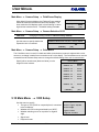
Main Menu → Sequencing → Multiscreen Dwell
Meaning:
1. From the Main Menu, select Sequencing, and press the ENTER key.
2. This opens another menu. In this menu, select Multiscreen Dwell, and
press the ENTER key.
When the indicated steps have been carried out, a menu or box appears, a discussion of
which completes the section.
These sections are either numbered, or else preceded by this symbol: c
In some boxes, particular items are highlighted on the screen. They can be distinguished
as follows:
Not highlighted:
Highlighted:
Camera 03
ENABLE
The unit provides user-friendly on-screen menus for entry of data such as titles or selecting options.
The options can also be accessed through the RS-232 port from a central controller or PC.
NOTE:
The ALARM key and on-screen symbols are disabled while the menu
system is active.
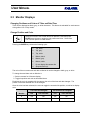
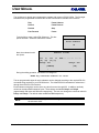
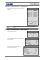
When MENU key is pressed, the Password Box appears.
Revision B
3-1
0150-0112
USER MANUAL
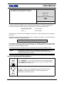
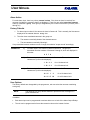
Password Box
For example, this box appears for a Calibur
16-camera unit running version 2.01 software.
MMX-165C
Ver 2.01
Please Enter the Password!
----
To enter the on-screen program menus, enter the 4-key password. The default passwords are:
To enter the on-screen menus, enter the 4-key password. The default passwords are:
FRZ, FRZ, FRZ, FRZ
for the operator.
3, 4, 7, 7
for the installer.
The defaults are set when units are shipped from the factory. These passwords can be changed in
the menus.
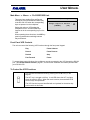
The Menu Bar displays all the programmable options in logical sub-sections. Four menu levels are
designed for ease in moving through them.
Main
QuickInstall
Operator
SystemView
The Installer password gives access to all four menus. The Operator password, on the other hand,
gives access only to the Operator and SystemView Menus. If an Operator tries to access the other
two menus, a password dialog box opens.
The QuickInstall section is a basic set of menu items that provide a quick installation setup.
NOTE:
Each section in this manual gives a description of choices that are
programmable through the menus. Read these sections in their entirety
before programming menu options.
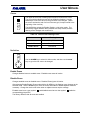
Keys for Operating and Entering Menus
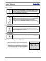
Use the ENTER key to go to the next menu level or to accept a parameter.
Use the MENU key to exit, or to back up one menu level, without making
any changes to the current level.
To access a menu, use the arrow keys to select, and then press the
ENTER key. Arrow keys can also be used to change values or
parameters in some of the menus.
0150-0112
3-2
Revision B
USER MANUAL
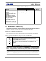
3.1 Pull-Down Menus
Pull-down menus are the top-level menus. Additional selections are available in the menus, and
choices are typically made in pop-up menus. To exit a pull-down menu, select Exit, and press
ENTER or the MENU key.
3.2 Pop-Up Menus
Pop-up menus are lower-level menus. Use the up/down arrow keys to select sections in the pop-up
menu, and then use the left/right arrow keys to change values.
To exit a Pop-up menu without making changes, press the MENU key or else select Cancel and press
the ENTER key. To exit and save the changes made, select OK and press the ENTER key.
CAUTION:
Pressing MENU to exit from a menu does not save the changes made in
that menu. In this instance, the MENU key has the same effect as does
the selecting Cancel and then pressing the ENTER key.
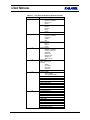
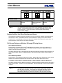
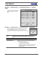
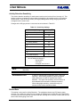
3.3 The Available Menus
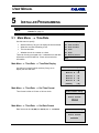
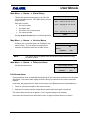
Highlight the selection using the left or right arrow keys, and press ENTER or the down arrow key.
When selected, one of the menus shown below appears on Monitor A.
Main
QuickInstall
Operator
SystemView
6
Time/Date
6
Change the Time
6
Field/Frame Display
6
View Screen 1
Sequencing
Change the Date
Sequencing
View Screen 2
Record
Edit Camera Titles
Time/Date Display
View Screen 3
Alarms
Camera Disable
Title Display
View Screen 4
Macro
Normal Record Speed
Playback Format
View Screen 5
Motion Detection
SVHS/Composite
Alarm History
View Screen 6
Camera Titles
VCR Level Type
Operator Password
Exit
Camera Setup
Installer Password
Normal Record Speed
VCR Setup
Auto Disable Now
Exit
Communications
Exit
Front Panel Lock
Factory Settings
Passwords
Exit
Revision B
3-3
0150-0112
USER MANUAL
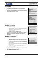
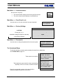
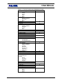
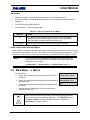
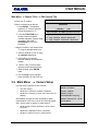
The Main Menu
The Main Menu provides access to all the programmable
options in logical sub-sections.
Time/Date
Read the corresponding section in the manual before starting to
program the options in the menus.
Record
Sequencing
Alarms
Macro
Motion Detection
Camera Titles
Camera Setup
VCR Setup
Communications
Front Panel Lock
Factory Settings
Passwords
Exit
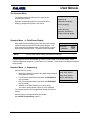
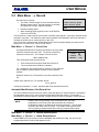
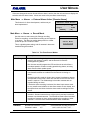
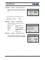
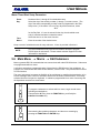
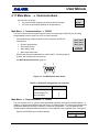
Main Menu → Time/Date
Time/Date Display
Use this menu to specify:
•
Which monitors (if any) are to display the time and date.
Set Time Format
•
What time and date formatting to use.
Set Date Format
•
The time and date.
Set Time
•
Whether the unit is a master or a slave.
Set Date
There can be only one master unit. It transmits time and date
information on the RS-485 line. Slave units receive this
information.
Set Master/Slave
Exit
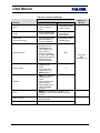
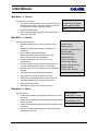
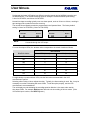
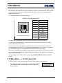
Main Menu → Sequencing
Multiscreen Dwell
Use this menu to specify:
•
Multiscreen dwell time (used for the sequencing cameos in
the multiscreen mode).
Live Full Dwell
•
Live full-screen dwell times (used when the SEQUENCE
key is pressed).
Salvo Switching
•
Play full-screen dwell times (used when the SEQUENCE
key is pressed).
•
How groups of cameras switch simultaneously on
Monitors B through E.
Play Full Dwell
Exit
The camera sequence list is programmed through the AutoList
feature.
See Installer Programming, page 5-1.
0150-0112
3-4
Revision B
USER MANUAL
Main Menu → Record
Record List
Use this menu to specify:
•
Normal Record Speed
The order in which images are to be recorded from the
different camera inputs. Use this selection to increase
the update rate of more important cameras.
•
Normal recording speed.
•
Alarm recording speed (typically 2-hour for NTSC/EIA,
3-hour for PAL/CCIR).
Alarm Record Speed
Exit
Main Menu → Alarms
Input Configuration
Use this menu to specify:
•
Whether the alarm input for each camera is N/O or
N/C.
Alarm Latch
•
Whether the alarms are Latched, Transparent, or
Timed-Out.
External Alarm Action
•
How to display associated cameras;
What action to take when an alarm is received;
How to set up a Salvo Switching group.
Enable/Disable
Alarm Action
Record Mode
Alarm History
•
External alarm action (for future use, not yet
implemented).
Link to a Macro
•
How the images from the alarmed cameras are to be
recorded (Interleaved, Exclusive or, No Change).
Relay Configuration
•
Whether some or all of the alarms are to be enabled or
disabled.
Video loss Action
•
Viewing of the history for the last 100 alarms.
•
Which macro runs when an alarm is received.
•
Alarms are to be displayed in full-screen mode only.
•
Whether the alarm output relays are N/O or N/C.
•
What activates the buzzer.
•
What action is taken when video loss occurs.
Fullscreen Alarm
Buzzer Setup
Exit
Main Menu → Macro
Macro Record
Use this menu to:
•
Initiate macro recording (and specify which macro is to be
recorded).
Timed Macro Start
•
Specify the parameters and schedules governing automatic
macro execution.
PLAY/RECORD Link
•
Initiate submacro editing (and specify which submacro is to
be edited).
Exit
•
Activate automatic transmission of the Play and Record
submacros to the VCR.
Revision B
3-5
Edit Submacro
0150-0112
USER MANUAL
Main Menu → Motion Detection
Use this menu to specify for each camera:
Enable/Disable Detection
•
Whether motion detection is enabled.
Setup Active Zones
•
Which zones in the camera’s view are to be
active for motion detection.
Indicate Detection
•
Whether a motion detection indicator is to be
displayed on the monitor.
Setup Parameters
•
Whether Activity Detection or Intrusion Detection
is desired.
•
Motion detection adjustments, the record rate to
be used, and the output relay to be activated (if
required).
Activity/Intrusion
Exit
Main Menu → Camera Titles
Title Display
Use this menu to specify:
•
Which monitors (if any) are to display the camera titles.
Edit Titles
•
The titles of each camera.
Exit
Main Menu → Camera Setup
Use this menu to specify for each camera:
Camera AGC
•
The AGC setting.
Camera Disable
•
Whether the camera is enabled or disabled.
Covert Camera
•
Whether the camera is Covert (not viewed on Live
display).
Camera Scope
Field/Frame Display
With Camera Scope, the user can display a digital
representation of the unit’s view of the incoming signals.
Camera Selection 16/32
Also, use this menu to specify for each camera:
Exit
•
Whether field or frame resolution is to be used in
full-screen.
•
Whether the Expansion Unit is connected.
•
Whether a camera is color or monochrome.
Color/Mono
Main Menu → VCR Setup
SVHS/Composite
This menu lets the user:
•
Select between SVHS and VHS (composite) tape.
Switch Input ON/OFF
•
Enable or disable VEXT.
Switch Edge
•
Specify either a positive or negative VEXT pulse.
Signal Level
•
Specify the VCR level.
Playback Format
•
Specify the playback format for proper tape decoding.
Exit
0150-0112
3-6
Revision B
USER MANUAL
Main Menu → Communications
Use this menu to specify:
RS232
•
The communication settings to be used for the RS-232 port.
RS485
•
The unit’s unique network address on the RS-485 bus.
Exit
Main Menu → Front Panel Lock
Unlock Keyboard
Use this menu to lock and unlock the front panel keyboard.
Lock Keyboard
Main Menu → Factory Settings
Password Box
CAUTION!
Please enter the Factory Password
Entering 8 ,1 ,1 ,1
----
resets ALL settings (except time and date)
[CANCEL]
[OK]
to the factory defaults!
Main Menu → Passwords
Use this menu to change the passwords for the menu system.
Installer Password
Operator Password
Exit
The QuickInstall Menu
The QuickInstall Menu presents options already discussed for the Main Menu.
See The Main Menu, page 3-4.
Change the Time
Change the Date
These options are required:
Edit Camera Titles
Camera Disable
Normal Record Speed
SVHS/Composite
These options are not required, but are recommended,
especially if VEXT is not used, or SVHS is desired:
VCR Level Type
Installer Password
Auto Disable Now
Read the corresponding section in the manual before
starting to program the options in the menus.
Revision B
3-7
Exit
0150-0112
USER MANUAL
The Operator Menu
The Operator Menu provides access to many of the
programmable options.
Field/Frame Display
Read the corresponding section in the manual before
starting to program the options in the menus.
Time/Date Display
Sequencing
Title Display
Playback Format
Alarm History
Operator Password
Normal Record Speed
Exit
Operator Menu → Field/Frame Display
With digital full-screen displays, the Field and Frame settings
switch the resolution between field and frame displays. The
lower resolution field displays result in less flickering on some
high-contrast camera scenes. The default setting is Frame.
NOTE:
Field/Frame Setup
Display
[CANCEL]
:
Frame
[OK]
This is a global system setting, and affects all cameras.
A symbol appears next to the time/date of Camera 1 when called to full-screen display. Field
resolution appears as a hyphen (-) when Camera 1 is selected. Frame Resolution displays no hyphen
when selected.
Operator Menu → Sequencing
Multiscreen Dwell
Use this menu to specify:
•
Multiscreen dwell time (used for the sequencing cameos in
the multiscreen mode).
Live Full Dwell
•
Live full-screen dwell times (used when the SEQUENCE
key is pressed).
Salvo Switching
•
Play full-screen dwell times (used when the SEQUENCE
key is pressed).
•
Whether or not Salvo Switching is to be enabled;
The order in which camera groups are to be displayed.
Play Full Dwell
Exit
The camera sequence list is programmed through the AutoList
feature.
Camera groups are programmed by the installer.
See Installer Programming, page 5-1.
0150-0112
3-8
Revision B
USER MANUAL
Operator Menu → Time/Date Display
Time and Date Display
Use this box to specify which monitors (if any) display the
time and date.
Monitor A : ON
Monitor B : ON
Monitor C : ON
Monitor D : ON
Monitor E : ON
[CANCEL]
[OK]
Operator Menu → Title Display
Use this box to specify which monitors (if any) display camera
titles.
Titles Display
Monitor A : ON
Monitor B : ON
Monitor C : ON
Monitor D : ON
Monitor E : ON
[CANCEL]
[OK]
Operator Menu → Playback Format
Use this menu to specify the playback mode. The unit can decode tapes
recorded on other multiplexers. If a tape from a Dedicated Micros or
Robot-compatible multiplexer is to be played back, the proper format must first
be selected from the unit’s menus. This setting can be found in the Playback
Format menu.
CBR+
CBR
SL/DM
ROBOT
Operator Menu → Alarm History
Alarm History Box
This box lets opens a window listing up to 100 of the
most recent alarm events. (The alarm history is kept in
a cyclic buffer.)
001 – 02/04 18:40:32 16
Each entry includes:
003 – 02/28 10:10:45 08
002 – 02/15 12:00:10 11
•
The event number.
•
:
The event’s date.
•
:
The event’s time (to the second).
•
The camera number.
010 – 03/15 05:12:16 04
[OK]
Use the up/down arrows to scroll through the list.
Revision B
3-9
0150-0112
USER MANUAL
Operator Menu → Operator Password
Password Box
Use this box to change the Operator password.
Enter a new Operator Password
---[CANCEL]
[OK]
Operator Menu → Normal Record Speed
Selecting either Fields or Hours adjusts the other. Typically,
the Hours setting is used. But, it may be necessary to use
the Field setting with some VCRs. To set this option
properly, see the VCR manufacturer’s recommendations.
Normal Record Speed
Fields
Hours
001
002
The System View Menu
Use this menu to examine the system’s current operating
parameters. This information is distributed among six screens, as
shown in Table 3-1 and Table 3-2 (pages 3-11 and 3-12).
View Screen 1
View Screen 2
View Screen 3
View Screen 4
View Screen 5
View Screen 6
Exit
0150-0112
3-10
Revision B
USER MANUAL
Table 3-1. The Six View Screens (Numerical Order)
View Screen
1
2
3
4
5
6
Revision B
Information Displayed
Alarm Input:
Enabled or disabled?
N/O or N/C?
Macro?
Alarm Action:
Freeze?
Camera
Relay
Monitor
External Action
Camera:
Enabled or disabled?
Signal gain
Covert?
Title
Video loss action:
Relay 1
Relay 2
Buzzer
Motion Detection:
Enabled or disabled?
Activity or intrusion?
Sensitivity
Record rate
Rejection ratio
Target size
Alarm camera
Record List
Salvo Switching List
Buzzers
Global?
Live Alarm?
Video loss?
Playback
Monitor displays of titles?
Monitor display:
Time and date?
Time and date formats
Master clock use?
Dwell times
Record speeds
Alarm latch
Alarm record mode
Fullscreen alarm?
Fullscreen display (field or frame?)
Salvo Switching
Auto Disable?
Indicate detection?
Baud rate
Network address
Playback format
VCR signal
VEXT pulse
VEXT edge
Factory settings
Keyboard lock?
Relay 1 (N/O or N/C?)
Relay 2 (N/O or N/C?)
3-11
0150-0112
USER MANUAL
Table 3-2. The Six View Screens (Alphabetical Order)
Information Displayed
Alarm Action:
Freeze?
Camera
Relay
Monitor
Alarm Input:
Enabled or disabled?
N/O or N/C?
Macro?
Alarm latch
Auto Disable?
Baud rate
Camera:
Enabled or disabled?
Signal gain
Covert?
Title
Dwell times
External Action
Factory settings
Fullscreen alarm?
Fullscreen display (field or frame?)
Indicate detection?
Keyboard lock?
Master clock use?
Monitor display:
Time and date?
Time and date formats
Monitor displays of titles?
Motion Detection:
Enabled or disabled?
Activity or intrusion?
Sensitivity
Record rate
Rejection ratio
Target size
Alarm camera
Network address
Playback format
Record speeds
Record List
Salvo Switching List
Buzzers
Global?
Live Alarm?
Video loss?
Playback
Relay 1 (N/O or N/C?)
Relay 2 (N/O or N/C?)
Salvo Switching
VCR signal
VEXT edge
VEXT pulse
Video loss action:
Relay 1
Relay 2
Buzzer
0150-0112
3-12
View Screen
1
5
6
2
5
1
6
5
6
5
4
3
6
6
5
4
6
5
6
2
Revision B
USER MANUAL
4
OPERATOR PROGRAMMING
NOTE:
For an explanation of the notation used in this chapter, see A Word About
Notation on page 3-1.
4.1 Operator Menu → Field/Frame Display
With digital full-screen displays, the Field and Frame settings
switch the resolution between field and frame displays. The
lower resolution field displays result in less flickering on some
high-contrast camera scenes. The default setting is Frame.
NOTE:
Field/Frame Setup
Display
[CANCEL]
:
Frame
[OK]
This is a global system setting, and affects all cameras.
A symbol appears next to the time/date of Camera 1 when called to full-screen display. Field
resolution appears as a hyphen (–) when Camera 1 is selected. Frame Resolution displays no
hyphen when selected.
4.2 Operator Menu → Sequencing
Multiscreen Dwell
Use this menu to specify:
•
Multiscreen dwell time (used for the sequencing cameos in
the multiscreen mode).
Live Full Dwell
•
Live full-screen dwell times (used when the SEQUENCE
key is pressed).
Salvo Switching
•
Play full-screen dwell times (used when the SEQUENCE
key is pressed).
•
Whether or not Salvo Switching is to be enabled;
The order in which camera groups are to be displayed.
Play Full Dwell
Exit
The camera sequence list is programmed through the AutoList
feature.
See Installer Programming, page 5-1.
The full-screen dwell time is the same for all monitors in the Live mode. Dwell time settings
determine the time interval between displays for each camera in the sequence list.
NOTE:
Revision B
The camera sequence lists for all monitors are programmed using the
AutoList feature. See AutoList and Sequencing, page 2-13.
4-1
0150-0112
USER MANUAL
Starting Full-Screen Sequencing on Any Monitor
1
After making sure that the desired camera is selected for control, select
any full-screen display by pressing the camera number, and then press
the SEQUENCE key.
Canceling Full-Screen Sequencing on Any Monitor
After making sure that the desired camera is selected for control, press
either the SEQUENCE key (again), or any camera number key.
3
Operator Menu → Sequencing → Multiscreen Dwell
Use this box to set the Multiscreen Dwell time in seconds.
The range is from 1 through 250, with a default value of 3.
Multiscreen Dwell
Similar boxes appear for Live Full Dwell and Play
Full Dwell.
(Time in Seconds)
002
Operator Menu → Sequencing → Salvo Switching
Salvo Enable
Use this menu to specify:
•
Whether or not Salvo Switching is to be enabled.
•
The order in which camera groups are to be displayed.
Salvo Setup
Exit
Operator Menu → Sequencing → Salvo Switching → Salvo Enable
This menu enables or disables Salvo Switching.
Salvo Switching
Enable : YES
[CANCEL]
[OK]
Operator Menu → Sequencing → Salvo Switching → Salvo Setup
Use this menu to program the order in which camera
groups are displayed in Salvo Switching.
Camera groups are programmed by the installer.
See Installer Programming, page 5-1.
0150-0112
4-2
Salvo Switching Setup
Index
:
01
Group
:
02
[CANCEL]
[OK]
Revision B
USER MANUAL
4.3 Operator Menu → Time/Date Display
Use this box to specify which monitors (if any) display the
time and date.
Time and Date Display
Monitor A : ON
Monitor B : ON
Monitor C : ON
Monitor D : ON
Monitor E : ON
[CANCEL]
[OK]
4.4 Operator Menu → Title Display
Use this box to specify which monitors (if any) display camera
titles.
Titles Display
Monitor A : ON
Monitor B : ON
Monitor C : ON
Monitor D : ON
Monitor E : ON
[CANCEL]
[OK]
4.5 Operator Menu → Playback Format
Use this menu to specify the playback mode. The unit can decode tapes
recorded on other multiplexers. If a tape from a Dedicated Micros or
Robot-compatible multiplexer is to be played back, the proper format must first
be selected from the unit’s menus. This setting can be found in the Playback
Format menu.
CBR+
CBR
SL/DM
ROBOT
Meanings of Abbreviations:
•
CBR+
Calibur Plus (default setting)
•
CBR
Calibur
•
SL/DM Calibur Lite; Dedicated Micros
•
ROBOT Robot
NOTE:
If a decoding format other than CBR+ is selected, CALIBUR tapes will not
be properly decoded.
Tapes that Can Not be Decoded
If the unit can not decode a tape being played back, the system displays a blank screen. The fields
are not decoded or separated. Two possible reasons why a tape can not be decoded are:
Revision B
4-3
0150-0112
USER MANUAL
•
The tape was not recorded on a multiplexer.
• The tape is not compatible with the decoding format selected in programming.
If the tape was actually recorded on a CALIBUR-compatible multiplexer, a Dedicated Micros unit, or
Robot unit, check to see that the correct PLAYBACK format has been selected in the menus.
{F}
Use the FUNCTION and PLAY to view the VCR output when nothing is
being decoded.
4.6 Operator Menu → Alarm History
Alarm History Box
This box lets opens a window listing up to 100 of the
most recent alarm events. (The alarm history is kept in
a cyclic buffer.)
001 – 02/04 18:40:32 16
Each entry includes:
003 – 02/28 10:10:45 08
002 – 02/15 12:00:10 11
•
The event number.
•
:
The event’s date.
•
:
The event’s time (to the second).
•
The camera number.
010 – 03/15 05:12:16 04
[OK]
Use the up/down arrows to scroll through the list.
4.7 Operator Menu → Operator Password
The following steps illustrate changing the Operator Password. See Main Menu → Passwords,
page 5-44, for information on changing the Installer password.
Enter the new password. Highlight [OK], and
press the ENTER key confirm it.
Password Box
Enter a new Operator Password
To leave the password unchanged, use
[CANCEL].
---[CANCEL]
When you have entered a new password, a
confirmation box is displayed where you must
enter the same password again. Again use [OK]
or [CANCEL] to complete this operation.
Confirmation Box
Please re-enter the Password
---[CANCEL]
0150-0112
4-4
[OK]
[OK]
Revision B
USER MANUAL
Message
If you select [OK] in the previous box,
this message appears.
If you select [CANCEL] instead, the
message reads:
The new Password has been accepted!
The Password was NOT changed!
[OK]
4.8 Operator Menu → Normal Record Speed
Unless VEXT (VCR sync pulse) is used for Normal and Alarm recording, the unit must be
programmed with the same record speeds as the VCR.
Dual-speed time-lapse VCRs allow two different recording speeds during Normal operation and Alarm
situations. The Alarm recording speed is usually the recorder’s fastest speed setting: 2-hour for
NTSC/EIA, and 3-hour for PAL/CCIR.
Normal time-lapse recording typically runs at a slower speed, such as 12-hour or 48-hour, resulting in
tape savings while no alarm events are occurring.
The Normal Record Speed can be programmed in the Operator Menu. The factory default setting is
2-hour for NTSC/EIA (3-hour for PAL/CCIR).
Selecting either Fields or Hours adjusts the other. Typically,
the Hours setting is used. But, it may be necessary to use
the Field setting with some VCRs. To set this option
properly, see the VCR manufacturer’s recommendations.
Normal Record Speed
Fields
Hours
001
002
The Fields value is the number of fields that each camera in the Record
List sends through the VCR output.
NOTE:
For most time-lapse VCRs, the Fields value corresponds to the record duration as follows:
Record Value
Fields Value
NTSC (hours)
PAL (hours)
001
2
3
003
6
6
005
8
12
007
12
18
009
16
24
011
20
30
013
24
36
For high-density or quasi-real-time VCRs, use the field value recommended in the VCR
manufacturer's manual.
The unit displays a code indicating the recording speed on Monitor A, the same code used by
time-lapse VCRs. For example, R024 appears when the unit is recording in 24-hour mode. (If the
VCR switch input is active, then REXT appears.)
Revision B
4-5
0150-0112
USER MANUAL
VCR Playback Speed
The playback speed must be selected at the VCR, not at the unit. The multiplexer automatically
matches the VCR playback speed.
The letter P appears on-screen to indicate the Play mode. The speed at which the information was
recorded follows the P. For example, P024 indicates the 24-hour recording speed (not the playback
speed).
To find out the playback speed, look at the VCR’s playback speed display. If the recording was made
using the camera switch VEXT input, then the mode and speed symbols read PEXT in Play mode.
NOTE:
The time and date displayed on-screen during Play mode are the recorded
time, not the current system time and date.
The letter V appears if there was video loss during the recording.
The abbreviation N/A appears on-screen if a camera is not detected on tape for several consecutive
cycles during playback. If the camera is not flagged as a video-loss camera, an N/A message
appears indicating not available.
This abbreviation helps to distinguish between:
•
Images not being updated during playback.
•
Images being updated from tape that contain no movement.
If an alarm occurred during recording, the letter A appears with the image on Monitor A.
0150-0112
4-6
Revision B
USER MANUAL
5
INSTALLER PROGRAMMING
NOTE:
For an explanation of the notation used in this chapter, see A Word About
Notation on page 3-1.
5.1 Main Menu → Time/Date
Time/Date Display
Use this menu to specify:
•
Which monitors (if any) are to display the time and date.
Set Time Format
•
What time and date formatting to use.
Set Date Format
•
The time and date.
Set Time
•
Whether the unit is a master or a slave.
Set Date
There can be only one master unit. It transmits time and date
information on the RS-485 line. Slave units receive this
information.
Set Master/Slave
Exit
Main Menu → Time/Date → Time/Date Display
Use this box to specify which monitors (if any) are to
display the time and date.
Time/Date Display
Monitor A : ON
Monitor B : ON
Monitor C : ON
Monitor D : ON
Monitor E : ON
[CANCEL]
[OK]
Main Menu → Time/Date → Set Time Format
Time format is either a 12-hour or 24-hour clock.
Time Format Setup
Select Format
24 HOUR
Main Menu → Time/Date → Set Date Format
Date format can be DD/MM/YY, MM/DD/YY, or YY/MM/DD.
Date Format Setup
Select Format
MM/DD/YY
Revision B
5-1
0150-0112
USER MANUAL
Main Menu → Time/Date → Set Time
Time Setup
Set the time as follows.
1. Press the ENTER key. The highlighting moves to the row of
numbers.
2. Enter the proper numerals for HH, MM, and SS. Use the
left/right arrow keys to move among the three fields. Use
the up/down arrow keys to change the numbers
themselves.
HH MM SS
12 13 30
[CANCEL]
[OK]
3. When finished, press the ENTER key again.
4. Use the arrow keys to select [OK].
5. Press the ENTER key again to confirm and exit.
Main Menu → Time/Date → Set Date
Date Setup
Set the date as follows.
1. Press the ENTER key. The highlighting moves to the row of
numbers.
2. Enter the proper numerals for MM, DD, YY, and Day. Use
the left/right arrow keys to move among the three fields.
Use the up/down arrow keys to change the numbers
themselves
MM DD YY Day
12 13 99
[CANCEL]
2
[OK]
3. When finished, press the ENTER key again. Use the arrow
keys to go to [OK].
4. Press the ENTER key again to confirm and exit.
The day of the week is specified by a number from 1 through 7. Day 1 of
the week varies with geographic location and local custom.
NOTE:
For example, if Sunday is day 1 and today is Wednesday, enter 4 as the
Day value.
This setting ensures that a scheduled macro (timed macro) is run on the
correct day of the week.
Main Menu → Time/Date
→ Set Master/Slave
Master/slave selection can be used to set one particular
multiplexer (of several in an installation) as a master clock. If
this is done, the time changes and daylight savings time need
to be changed on the master unit only.
Master/Slave Select
Master Clock : NO
[CANCEL]
[OK]
The master clock controls the time and date display for the
other multiplexers in the RS-485 network. For master/slave
selection to function properly, each multiplexer in the network
must be separately set up through the menu.
NOTE:
0150-0112
There can be only one master clock. The rest must be slaves.
5-2
Revision B
USER MANUAL
5.2 Main Menu → Sequencing
Multiscreen Dwell
Use this menu to specify:
•
Multiscreen dwell time (used for the sequencing cameos in
the multiscreen mode).
Live Full Dwell
•
Live full-screen dwell times (used when the SEQUENCE
key is pressed).
Salvo Switching
•
Play full-screen dwell times (used when the SEQUENCE
key is pressed).
•
How groups of cameras switch simultaneously on
Monitors B through E.
Play Full Dwell
Exit
The camera sequence list is programmed through the AutoList
feature.
The full-screen dwell time is the same for both all monitors in Live and Play modes. Dwell time
settings determine the time between each camera in the sequence list.
NOTE:
The camera sequence list for all monitors are programmed using the
AutoList feature. See AutoList and Sequencing, page 2-13.
Main Menu → Sequencing → Multiscreen Dwell
Use this box to set the Multiscreen Dwell time in seconds.
The range is from 1 through 250, with a default value of 3.
Multiscreen Dwell
Similar boxes appear for Live Full Dwell and Play
Full Dwell.
(Time in Seconds)
002
Main Menu → Sequencing → Salvo Switching
Salvo Enable
Use this menu to specify:
•
Whether or not Salvo Switching is to be enabled.
•
The order in which camera groups are to be displayed.
Salvo Setup
Exit
Main Menu → Sequencing → Salvo Switching → Salvo Enable
This menu enables or disables Salvo Switching.
Salvo Switching
Enable : YES
[CANCEL]
[OK]
Main Menu → Sequencing → Salvo Switching → Salvo Setup
Use this menu to program the order in which camera
groups are displayed in Salvo Switching.
Camera groups are programmed by the installer.
See Installer Programming, page 5-1.
Revision B
5-3
Salvo Switching Setup
Index
:
01
Group
:
02
[CANCEL]
[OK]
0150-0112
USER MANUAL
5.3 Main Menu → Record
Record List
Use this menu to specify:
•
The order in which images are to be recorded from the
different camera inputs. Use this selection to increase
the update rate of more important cameras.
•
Normal recording speed.
•
Alarm recording speed (typically 2-hour for NTSC/EIA,
3-hour for PAL/CCIR).
Normal Record Speed
Alarm Record Speed
Exit
The Record List is used to set the record order of camera output signals. Up to thirty cameras can be
selected in any order. This allows the same camera number to be repeated in the list as required to
increase the update rate or camera priority on the VCR.
Also, in this menu, set the normal record speed for the VCR (time-lapse speed), the alarm record
speed (2-hour for NTSC/EIA, 3-hour for PAL/CCIR).
Main Menu → Record → Record List
A programmed Record List controls the sequence of single fields
from each camera sent to the VCR. The list can contain any
camera more than once. For example, if the list is set to:
12333456785_
Record List
Index : 01
Camera : 01
[CANCEL]
[OK]
Then, among the fields recorded will be:
•
Three consecutive and unique fields from Camera 3.
•
Two non-consecutive fields from Camera 5.
For a multiplexer, the programming for Camera 5 is the preferred
way to repeat a camera because it results in evenly spaced
updates.
Repeat a camera only if it has priority over other cameras in the
list.
A blank entry ends the list. For example, the list:
123_5678
records only cameras 1, 2, and 3, the blank after the 3 ends the Record List.
Automatic Modification of the Record List
The unit modifies the Record List in the case of video loss alarms or activity detection, according to
the parameters set up by the user in the Alarm and Motion Detection menus. For example, if
Interleaved recording on alarm is selected, a single camera in alarm is recorded in virtual real time.
NOTE:
If alarms and activity detection occur at the same time, the alarm
modifications to the Record List take precedence and cancel all
modifications made to the Record List by activity detection. The unit does
not control the setup of the VCR itself. The installer must ensure that the
VCR is properly programmed and has correctly connected alarm inputs.
Main Menu → Record → Normal Record Speed
Main Menu → Record → Alarm Record Speed
Unless VEXT (VCR sync pulse) is used for NORMAL and ALARM recording, the unit must be
programmed with the same record speeds as VCR.
0150-0112
5-4
Revision B
USER MANUAL
Dual-speed time-lapse VCRs allow two different recording speeds during NORMAL operation and
ALARM situations. The ALARM recording speed is usually the recorder’s fastest speed setting:
2-hour for NTSC/EIA, and 3-hour for PAL/CCIR.
Normal time-lapse recording typically runs at a slower speed, such as 12-hour or 48-hour, resulting in
tape savings while no alarm events are occurring.
The normal Record Speed can also be programmed in the Operator Menu. The factory default
setting is 2-hour for NTSC/EIA, (3-hour for PAL/CCIR).
Normal Record Speed
Fields
001
Alarm Record Speed
Hours
Fields
002
001
Hours
002
The Fields value is the number of fields that each camera in the Record
List sends through the VCR output.
NOTE:
For most time-lapse VCRs, the Fields value corresponds to the record duration as follows:
Record Value
Fields Value
NTSC (hours)
PAL (hours)
001
2
3
003
6
6
005
8
12
007
12
18
009
16
24
011
20
30
013
24
36
For high-density or quasi-real-time VCRs, use the field value recommended in the VCR
manufacturer's manual.
Selecting either Fields or Hours adjusts the other. Typically, the Hours setting is used. But, it may be
necessary to use the Field setting with some VCRs. To set this option properly, see the VCR
manufacturer’s recommendations.
The unit displays a code indicating the recording speed on Monitor A, the same code used by
time-lapse VCRs. For example, R024 appears when the unit is recording in 24-hour mode. (If the
VCR switch input is active, then REXT appears.)
Revision B
5-5
0150-0112
USER MANUAL
5.4 Main Menu → Alarms
The standard unit is equipped with one alarm input per camera output, each associated with its Live
video input. An alarm input displays an on-screen warning on all monitors, flashes a front panel LED,
sounds an internal buzzer, and changes Record List priority.
Input Configuration
Use this menu to specify:
•
Whether the alarm input for each camera is N/O or
N/C.
Alarm Latch
•
Whether the alarms are Latched, Transparent, or
Timed-Out.
External Alarm Action
•
How to display associated cameras;
What action to take when an alarm is received;
How to set up a Salvo Switching group.
Enable/Disable
Alarm Action
Record Mode
Alarm History
•
External alarm action (for future use, not yet
implemented).
Link to a Macro
•
How the images from the alarmed cameras are to be
recorded (Interleaved, Exclusive or, No Change).
Relay Configuration
•
Whether some or all of the alarms are to be enabled or
disabled.
Video loss Action
•
Viewing of the history for the last 100 alarms.
•
Which macro runs when an alarm is received.
•
Alarms are to be displayed in full-screen mode only.
•
Whether the alarm output relays are N/O or N/C.
•
What activates the buzzer.
•
What action is taken when video loss occurs.
Fullscreen Alarm
Buzzer Setup
Exit
Alarms trigger on-screen displays of a flashing letter A in each corresponding cameo on multiscreen.
The symbol is ALM on:
•
Any full-screen display.
•
Any display of cameras in alarm on Monitors B through E.
0150-0112
5-6
Revision B
USER MANUAL
Main Menu → Alarms → Input Configuration
The alarm inputs are configured as zero potential relay
contacts, individually programmable as normally open
(N/O) or normally closed (N/C). To set the alarm input
configuration to N/O or N/C, use the Input Configuration
section of the Alarm menu (shown below). The factory
default is N/OPEN.
Alarm Input
Alarm
01:
N/OPEN
Alarm
02:
N/CLOSED
Alarm
03:
N/OPEN
Alarm
04:
N/OPEN
Alarm
05:
N/OPEN
Alarm
06:
N/CLOSED
Alarm
07:
N/OPEN
:
:
:
Alarm
16:
N/OPEN
↓↓↓
[CANCEL]
[OK]
NOTE:
In this menu, as in some others, a set of three arrows appears:
↓↓↓
These arrows mean that the entire list is too long for the available display
area.
To see the next group of selections, highlight the arrows, and then press
the ENTER key.
Main Menu → Alarms → Alarm Latch
Alarm latching determines how the unit responds to alarm inputs.
Latched
Transparent
Timed Out
Revision B
5-7
0150-0112
USER MANUAL
There are three types of alarm latching, as shown in Table 5-1.
Table 5-1. The Three Types of Latching
Type
Description
Latched
Alarms are latched until silenced and acknowledged. A new input
restarts the alarm.
Timed Out
Timed-out alarms are latched for a preset period from the start of
alarm activation. When the preset interval times out, the alarm is
silenced and acknowledged. The time-out period is a
programmable selection in the menu.
If an alarm input is still active after the time-out, the alarm LED
remains on.
If an alarm ceases and restarts before the time-out period ends,
the time-out period starts over.
Timed-out alarms can be silenced and acknowledged at any time.
Like latched alarms, if the alarm is canceled, it is silenced and
acknowledged, and does not reactivate until new input occurs.
Transparent
(not Latched
or Timed)
Alarms are active only while the alarm input is active. As soon as
the alarm-input ceases, the alarm is silenced and acknowledged.
Main Menu → Alarms → Alarm Latch → Timed Out
Alarm Timeout
Use this box to set the time-out interval in seconds. The range
is from 1 through 250.
(Time in Seconds)
020
NOTES:
A Transparent alarm can not be silenced or acknowledged. It remains
active as long as the corresponding alarm input is active.
If the ability to silence or acknowledge active alarms is desired and
Transparent mode is preferred, select Timed Out alarms in the Alarm
Latching menu, and set the time-out period to two seconds.
Main Menu → Alarms → Alarm Action
Alarm Action Setup
See the discussion below.
Input (Group): 01
Freeze
: YES
Cameras
: 16 01 02 03
Presets
: -- -- -- --
Relay
: 1
Aux Monitor
: B
[CANCEL]
0150-0112
5-8
[OK]
Revision B
USER MANUAL
Alarm Action
For each alarm input, there is a primary camera in alarm. But, when an alarm is received, four
cameras (including the camera in alarm) are displayed. These four are called associated cameras,
and they constitute a group. Each group is designated by the number of the alarm input itself (from 1
through 16).
Factory Defaults
1.
For alarm input number N, the camera in alarm is Camera N. This is normally the first camera
displayed in the Alarm Action Setup box.
2.
The other three associated cameras in the group are:
•
The camera numerically ahead of the alarmed camera.
•
The two cameras numerically following it.
If any associated camera numbers are out of range, the selection "wraps around" accordingly.
EXAMPLES:
1)
For alarm input 6, the camera in alarm is Camera 6. The group of
associated cameras consists of Cameras 5 through 8, which are displayed in
this order:
6 5 7 8
2)
3)
For alarm input 1, the camera in alarm is Camera 1. The associated
cameras are (in the order displayed):
1 16 2 3
for a 16-channel unit
1 32 2 3
for a 32-channel unit
For alarm input 16, the camera in alarm is Camera 16. The associated
cameras are (in the order displayed):
16 15
1
2
for a 16-channel unit
16 15 17 18
for a 32-channel unit
User Options
The factory defaults are changeable by the programmer, who can select the cameras constituting
each group.
NOTE:
The cameras in a group should selected to provide the best coverage for a
given alarmed area.
In addition:
•
Each alarm input can be programmed to activate either one or both of the Alarm Output Relays.
•
The unit can be programmed to freeze the camera-in-alarm at the instant of alarm.
Revision B
5-9
0150-0112
USER MANUAL
Presets
Cameras equipped with telemetry capabilities can be programmed to a preset view in an alarm
situation. These presets are programmed in the camera controls, not in the multiplexer. Calibur
units support Presets 1 through 16. Telemetry-equipped cameras may have more or fewer.
Alarm Action Setup
In this box:
•
Camera 16 is programmed to Preset 2.
Input (Group): 01
•
Camera 1 is programmed to Preset 1.
Freeze
: YES
•
The remaining two cameras are not
programmed.
Cameras
: 16 01 02 03
Presets
: 02 01 -- --
Relay
: 1
Aux Monitor
: B
Note that the double hyphen (--) symbol signifies
that no presets have been programmed (or that
the camera is not telemetry-equipped). This is the
factory default for all cameras.
[CANCEL]
[OK]
After entering the appropriate Preset value for each programmed camera, select [OK] to close the
box and store the information.
Freezing Alarms on Monitor A in Live Mode
The programmer can choose to have the camera in alarm frozen at the instant of the alarm by
selecting YES in the menu. The factory default for all alarm inputs is that the camera in alarm is
frozen when the alarm input is received.
NOTE:
If an additional alarm is received while some cameras are already frozen:
The frozen cameras become unfrozen and immediately re-frozen at the
instant the new alarm input is received.
The associated cameras are not frozen at the instant of alarm. This allows the programmer to freeze
the instant of alarm while continuing to track ongoing activity on the same screen.
APPLICATION
NOTE:
If one of the associated cameras is the same as the camera in alarm:
A frozen image of the camera in alarm, as well as a Live image of the
same camera, appear on Monitor A at the same time.
This approach is not needed if Monitors B through E are installed.
Depending on the number of simultaneous alarm inputs, the multiplexer selects a customized alarm
display. This display shows all cameras in alarm, as well as the associated cameras. The custom
screens are automatic for up to three simultaneous alarms.
0150-0112
5-10
Revision B
USER MANUAL
First Alarm
Second Alarm
Third Alarm
Cameras in alarm
Top left cameo.
Top two cameos.
Top three cameos.
Associated cameras
The remaining
cameos.
Three of the four
cameos below each
top cameo.
The remaining
cameos.
NOTE:
The custom alarm screens on Monitor A are displayed only while an alarm
is active. Once an alarm times out or is cleared, the display reverts to the
previous screen. It is very important to select the best alarm-latching
mode for alarm displays.
Displays for More than Three Simultaneous Alarms
If more than three alarms are active at the same time, the unit selects a display format showing all
the cameras in alarm. Associated cameras are not selected for display, nor are alarms frozen.
Usually, this is a 9-way display, unless more than nine cameras are in alarm at the same time. As
each new alarm is received, the unit adjusts the display.
Full-Screen Displays on Monitors B through E During Alarms
Salvo Switching Disabled
During alarms, the monitor (B through E) designated as Aux Monitor in the menu switches to a
full-screen display of the camera in alarm. The other monitors continue to display their current
cameras and not change due to alarm.
If multiple alarms are active, the designated Aux Monitor sequences among the alarm cameras at a
fixed 1-second dwell, which is not programmable. Monitors B through E cannot freeze images on
alarm.
Salvo Switching Enabled
During alarms, the Aux Monitor setting has no effect. Monitors B through E switches to a full-screen
display of the cameras programmed as the Input Group in the Alarm Action Setup menu.
For example, if input alarm 01 is activated, Group 01 cameras display on Monitors B through E.
If multiple alarms are active, Monitors B through E sequence between the alarm camera Groups at a
fixed 1-second dwell. This dwell is not programmable. Monitors B through E cannot freeze images
on alarm.
NOTE:
Revision B
The Monitors B through E screens do not revert to original fixed displays
after the alarm is cleared. They continue to display the last alarm camera.
But, if sequencing was active on Monitors B through E before the alarm,
then Monitors B through E continue to sequence after the alarm is cleared.
5-11
0150-0112
USER MANUAL
If the user changes the screen format while an alarm is active, then the unit continues to display the
selection after the alarm clears. It does not revert to the pre-alarm screen display.
Main Menu → Alarms → External Alarm Action [Remote Alarms]
External Alarm Action
This feature is for future development, and has not yet
been implemented.
Remote Input
: 01
Output
: NONE
[CANCEL]
[OK]
Main Menu → Alarms → Record Mode
Use this menu to select among No Change recording,
Exclusive recording, or Interleaved recording as the response
to an alarm. The latter two modes always result in a faster
update to tape of a camera in alarm.
This is a global system setting, and all cameras in alarm are
recorded using this method.
Alarm Record Mode
Select Mode
INTERLEAVED
Table 5-2. The Three Record Modes
Mode
Description
No Change
In this mode, recording during alarms means no that priority recording
exists for the cameras in alarm, and the Record List remains
unchanged during alarms.
But, the user can still program the VCR and the unit to switch from a
time-lapse speed to a faster recording speed during alarms, ensuring
alarm events a faster update speed.
Exclusive
In this mode, the system records only alarmed cameras. All
non-alarmed cameras are omitted from the Record List during an
alarm.
Exclusive recording mode is chosen when several simultaneous alarms
are expected to occur often, and a near real-time record of those alarm
events is required. The disadvantage is that other cameras are not
recorded during an alarm.
If Exclusive alarm recording is selected, the alarm input sensors must
be very sensitive and reliable, so that alarm events are not missed, and
the system does not initiate exclusive alarm mode recordings for false
alarms.
Interleaved
EXAMPLE:
In this mode, both the alarmed cameras and non-alarmed cameras are
recorded. Alarmed cameras have a higher priority and are interleaved
between non-alarmed cameras. The Interleaved mode offers increased
recording of cameras in alarm, without stopping the recording of other
cameras. This is the mode recommended for most installations.
Non-alarmed cameras: 1,2,3,5,7
Cameras in alarm:
0150-0112
4,6
5-12
INTERLEAVED recording sequence:
1,4,6,2,4,6,3,4,6,5,4,6,7,4,6,1, . . .
Revision B
USER MANUAL
NOTE:
In general, Interleaved recording provides quick updates of cameras in
alarm (including multiple alarms.) Interleaved mode is the recommended
setting.
Main Menu → Alarms → Enable/Disable
Individual Enable
This selection offers three options:
•
Individual Enable: Allows individual alarms to be
enabled or disabled.
Enable All
•
Enable All: Globally enables all alarm inputs.
Exit
•
Disable All: Globally disables all alarm inputs.
Disable All
Main Menu → Alarms → Enable/Disable→
→ Individual Enable
Selecting Individual Enable in the previous menu
opens this menu. Each camera can be individually
enabled or disabled.
Alarms Enable
Alarm
01:
ENABLE
Alarm
02:
DISABLE
Alarm
03:
ENABLE
Alarm
04:
ENABLE
Alarm
05:
ENABLE
Alarm
06:
DISABLE
Alarm
07:
ENABLE
:
:
:
Alarm
16:
ENABLE
↓↓↓
[CANCEL]
Revision B
5-13
[OK]
0150-0112
USER MANUAL
Main Menu → Alarms → Alarm History
Alarm History Box
This box lets opens a window listing up to 100 of the
most recent alarm events. (The alarm history is kept in
a cyclic buffer.)
001 – 02/04 18:40:32 16
Each entry includes:
003 – 02/28 10:10:45 08
002 – 02/15 12:00:10 11
•
The event number.
•
:
The event’s date.
•
:
The event’s time (to the second).
•
The camera number.
010 – 03/15 05:12:16 04
[OK]
Use the up/down arrows keys to scroll through the list.
Main Menu → Alarms → Link to a Macro
An alarm input (or several inputs) can be linked to any
macro function. This can start a pre-programmed
sequence of keystrokes each time an alarm occurs.
Macro Link List Setup
Alarm
: 01
Macro
:
[CANCEL]
NOTE:
[OK]
The system always completes other normal alarm actions before executing
the macro function.
Main Menu → Alarms → Fullscreen Alarm
Fullscreen Alarm
See the discussion below.
Fullscreen (Mon A): NO
[CANCEL]
[OK]
Full-Screen Alarm
If the programmer does not install Monitors B through E and relies solely on Monitor A for all system
information, a full-screen alarm display on Monitor A may be preferred to the custom multiscreen
displays.
In this case, the programmer can select a menu option in the Alarms menu that makes Monitor A:
•
Switch to a full-screen display of the camera in alarm.
•
Sequence full-screen between multiple alarms (as Monitors B through E normally do).
The custom alarm screens do not appear. (This is a global setting for all cameras).
If the option was selected in the Alarm Action menu, a single full-screen alarm is not frozen.
0150-0112
5-14
Revision B
USER MANUAL
Main Menu → Alarms → Relay Configuration
This box allows each relay to be configured as N/OPEN
(normally open, N/O) or N/CLOSED (normally closed,
N/C).
Relay Configuration
Relay 1:
N/OPEN
Relay 2:
N/CLOSED
[CANCEL]
[OK]
Factory default settings for Alarm Output Relays are:
All Alarm Inputs
activate
All Motion Detection activates
Relay 1
Relay 2
Main Menu → Alarms → Buzzer Setup
The internal buzzer can be programmed to respond
under various conditions.
Turn this buzzer
OFF:
Live Alarm
Video loss
Playback
Global
If buzzer response is not
desired:
On incoming Live alarms
On video loss detection
During playback of
videotapes where alarms are
present
All of the above
Buzzer Setup
Global Buzzer
: ON
Live Alarm Buzzer : ON
Video Loss Buzzer : ON
Playback Buzzer
: ON
[CANCEL]
[OK]
Main Menu → Alarms → Video loss Action
This box specifies what happens when there is loss of
video input. Video loss can occur due to a failed camera
or disconnection of the video signal to the multiplexer.
Video loss Action
Camera
: 01
Relay 1
: DISABLE
Relay 2
: DISABLE
Buzzer
: DISABLE
[CANCEL]
Revision B
5-15
[OK]
0150-0112
USER MANUAL
Indications
•
Multiscreen displays: The letter V appears on-screen in each affected cameo.
•
Full-screen displays: The abbreviation VDL appears on-screen when the affected camera is
displayed.
•
An LED below the ALARM key blinks.
•
A buzzer sounds. (This is programmable.)
Table 5-3. Video Loss Action in Live Mode
Monitor
Action
A
If a camera is being displayed while video loss occurs, the camera
image freezes. But, if sequencing is in progress, the display blanks
when switched to a camera experiencing video loss.
B through E
Display goes blank when a camera with video loss is selected.
Video Loss Action in Record Mode
When video loss is detected, the affected camera is temporarily removed from the Record List, and
the video loss information is recorded. This video loss status is displayed during playback. The unit
continues to monitor video loss cameras, and displays the cameras when video signal is restored.
The unit allows the user to disable cameras that are not connected or are
out of service for an extended time. In this way, unnecessary video loss
messages can be avoided.
NOTE:
See Main Menu → Camera Setup → Camera Disable, page 5-35.
5.5 Main Menu → Macro
Macro Record
Use this menu to:
•
Initiate macro recording (and specify which macro is to be
recorded).
Timed Macro Start
•
Specify the parameters and schedules governing automatic
macro execution.
PLAY/RECORD Link
•
Initiate submacro editing (and specify which submacro is to
be edited).
•
Activate automatic transmission of the Play and Record
submacros to the VCR.
{F}
1
0150-0112
Edit Submacro
Exit
Macro Functions provide for recording of frequently used key sequences
and menu setups as two-keystroke operations. The FUNCTION key plus
the macro number (1 through 16) begins execution. Pressing the
FUNCTION key cancels a macro.
5-16
Revision B
USER MANUAL
Main Menu → Macro → Macro Record
Macro Record
Select the macro's number.
Select Macro
01
To begin recording, select Macro Record in the Macro menu, and then select one of the macros by
number (1 through 16). Upon selection, the system exits the menus and goes to a reference point
(starting point), from which all subsequent keystrokes are recorded into that macro.
NOTE:
The letter F and the macro number appear on the screen while macro
recording is active.
{F}
Each keystroke is recorded, until the FUNCTION and ENTER keys are
pressed (in that order) to end the macro recording, or until 32 keystrokes
have been entered.
Each use of the MENU key counts as one keystroke in the macro. If the
menus are accessed during macro recording, the keystrokes are canceled.
Instead of recording keystrokes while in the menus, this process records
only the final settings of all setup parameters for those menus.
Special Keys Functions During Macro Record
The following two-key combinations allow special actions within macros:
FUNCTION, then 1.
{F}
Activate output relay 1.
1
Revision B
FUNCTION, then 2.
Reset output relay 1.
FUNCTION, then 3.
PAUSE macro, 1 second.
FUNCTION, then 4.
PAUSE macro, 5 seconds.
FUNCTION, then 5.
Activate output relay 2.
FUNCTION, then 6.
Reset output relay 2.
FUNCTION, then ENTER .
End macro recording.
5-17
0150-0112
USER MANUAL
When running a macro, the unit retrieves only the recorded menu setup parameters, and sets up the
unit accordingly. Parameters in menus not accessed during macro recording are not recorded or
retrieved during playback.
New menu setups can run manually, automatically by time and day, or when activated by an alarm.
See Main Menu → Macro → Timed Macro Start (page 5-19), or Main Menu → Alarms →
Link to a Macro (page 5-14).
Typical uses of this unique macro feature are:
•
Different display screens.
•
Different sequence tables.
•
Different recording modes or playback format.
•
Disable or Enable Cameras, Alarms and Motion Detection.
Macro Limitations
Alarms and motion detection can only be enabled and disabled by means of macros. Other alarm
and motion detection parameters can not be set with macros
The following parameters can not be set up with a macro, and should be set up during installation:
•
Output Relay selection: 1, 2 (or both) per input.
•
Alarm inputs and Output Relays contact configuration: N/O or N/C.
•
Whether the M indicator is on or off during motion detection.
•
Video loss relays and buzzer selections per input.
•
VCR switch pulse edge selection.
•
Alarm action parameters.
NOTE:
Because of extensive memory requirements, some parameters (such as
motion detection grids) can not be changed with a macro function. But,
they can be set up through the RS-232 port.
Ending Macro Recording
{F}
Press FUNCTION and ENTER keys (in that order) to end the recording of
a Macro.
RECOMMENDATION:
0150-0112
Make a list of each macro function and its number for later
reference. See Section 9.
5-18
Revision B
USER MANUAL
Editing a Macro
{F}
There is no macro editing capability. To check a macro function, run the
macro by pressing the FUNCTION key and the macro number, and check
for correct operation. If the macro does not function properly, delete the
macro as described below, and re-enter it.
Deleting a Macro
{F}
Delete a macro by recording an empty macro over it. To record an empty
macro, start macro recording from the Macro Record menu and
immediately press the FUNCTION and ENTER keys to end the recording.
Running a Macro
{F}
A macro can be played by pressing the FUNCTION key followed by the
macro number (1 through 16). While the macro is running, the letter F and
the macro number appear on Monitor A.
1
Canceling a Macro
{F}
A macro can be canceled during its playback by pressing the FUNCTION
key.
Main Menu → Macro → Timed Macro Start
Macros can be preset to run at a fixed time and day of the
week by using Timed Macro Start. This menu allows
programming of up to 20 events that run automatically.
Scheduled events can be preset to start at any time and day
or at a preset time every day. Any macro can be started by
each of 20 scheduled events or by multiple events.
Timed Macro Setup
Event
: 01
Day
: 00
Time
: 00:00
Macro
: 01
[CANCEL]
Revision B
5-19
[OK]
0150-0112
USER MANUAL
Macro Timed-Start Setup Parameters
Event:
Numbered from 1 through 20 for scheduled events.
Day:
Select the day of the week by number (1 through 7) to start a macro. (The
day of the week corresponding to today’s date is programmed in the Date
Setup menu.) If the macro is to run every day at the same time, select
**
for the Day field. If a zero is entered for the day, the scheduled event
entry is canceled and does not start the macro.
Time:
Select the time to run the macro function.
Macro:
Enter the number of the desired macro.
Keep a record of scheduled events for easy reference. A form is provided in Section 8.
NOTE:
It is recommended that only experienced installers attempt to program
RS-232 bytes for submacros. Please contact technical support for further
information or assistance.
5.6 Main Menu → Macro → Edit Submacro
Macros generate RS-232 commands that can communicate with other RS-232 devices. Submacros
are programmed within a macro.
A submacro transmits a programmed string of bytes from the RS-232 port of the multiplexer. Its
purpose is to communicate with other RS-232 devices, such as VCRs. This permits RS-232 control
of VCR functions.
The use of submacros increases the flexibility of the multiplexer by enabling the transmission of an
RS-232 message when a macro is activated. Macros can be timed, linked to alarms, or manually
activated from the front panel or keyboard. A submacro programmed into a macro runs along with
the keystrokes recorded in a stored macro.
ALT
To program a submacro to activate within a macro, begin normal macro
recording as noted above.
{F}
Then press the ALT key, then the FUNCTION key, and finally the
submacro's number key.
1
{F}
After entering the remaining characters, end the macro recording by
pressing the FUNCTION and ENTER keys.
0150-0112
5-20
Revision B
USER MANUAL
The multiplexer is already pre-programmed to operate with common RS-232 VCRs. The first eight
submacros are programmed to emulate the RS-232 commands for standard VCR functions:
Play
Frame Advance
Record
Frame Reverse
Rewind
Stop
Fast Forward
Freeze
From the Macro menu, select Edit Submacro. This box
opens as shown. Select the submacro's number.
Submacro Edit
Select Submacro
01
Submacro 01 Edit
Next, the submacro's edit
box opens.
000
066
013
010
[P]
[B]
[X] [Y]
--- --- --- --- --- ---
Delay1: 237
Delay2: 239
[CANCEL]
[OK]
ENTER key starts Submacro edit
During the editing operation, the bottom line changes to:
ENTER key terminates Submacro at cursor
The ten programmable bytes for each submacro can be changed according to the required RS-232
command string required for your RS-232 device. The default RS-232 commands for submacros 1
through 8 are RS-232 VCR functions.
Each submacro string byte can be set to any value from zero through 255. In addition, two delay
values can be transmitted instead of bytes. These delays are labeled Delay1 and Delay2
(approximately 200 msec and 500 msec respectively). The user can change the numerical codes for
Delay1 and Delay2. The default codes are 237 and 239 respectively.
NOTE:
Revision B
Be sure to choose delay codes from among numbers that are not used in
the submacro itself.
5-21
0150-0112
USER MANUAL
Main Menu → Macro → PLAY/RECORD Link
This menu item enables Play and Record
commands to be transmitted simultaneously
to the RS-232 VCR when the corresponding
keys are pressed on the multiplexer.
RECORD/PLAY keys
Always couple to macros? : NO
[CANCEL]
Setting this option to YES makes the
multiplexer's PLAY and RECORD keys
function as do the corresponding keys on the
VCR.
[OK]
When operating these functions, the LIVE key
must be pressed when switching between
Play and Record.
Front Panel VCR Controls
The unit can control the following VCR functions through the front panel keypad.
Play
Frame Advance
Record
Frame Reverse
Rewind
Stop
Fast Forward
Freeze
To access these control functions, the multiplexer must be connected to the VCR through the RS-232
port. See RS-232 Remote Protocol, page 8-1, as well as the installation information provided with
your RS-232 VCR.
To Control the VCR Functions
First, activate the Alternate mode by pressing the red ALT key on the
keypad.
ALT
The ALT key is a toggle on/off key. A red LED above the ALT key lights
when the mode is active. When the mode is active, the associated VCR
function keys are operational.
The VCR function keys are identified with red symbols for the action they
perform while in this mode.
0150-0112
5-22
Revision B
USER MANUAL
The VCR functions keys activated in the Alternate mode are as follows:
Key
Play
PLAY
VCR PLAY
Record
RECORD
VCR REC
Rewind
Left Arrow
VCR REW
Fast forward
Right Arrow
VCR FF
Frame advance
Up Arrow
VCR F ADV
Frame reverse
Down Arrow
VCR F REV
Stop
ENTER
VCR STOP
Pause
FREEZE
VCR PAUSE
†
NOTE:
Indicator †
Function
In the Alternate mode, on-screen indicators appear for a few
seconds after the selected function is initiated. These indicators
appear in any monitor display mode.
To turn off the Alternate mode and return to normal keypad operations
after performing the VCR functions, press the ALT key again.
5.7 Main Menu → Motion Detection
Enable/Disable Detection
These options are discussed below.
Setup Active Zones
Indicate Detection
Activity/Intrusion
Setup Parameters
Exit
The units offer complete motion detection, including built-in false alarm rejection, sensitivity settings,
and size discrimination per camera. Motion detection is used to adjust the rate at which cameras are
recorded (Activity Detection), and as an intrusion alarm sensor to trigger an alarm input (Intrusion
Detection).
The difference between Intrusion detection and Activity detection is useful when digital video motion
detection is used. An ability to reduce false motion alarms is a major difference between intrusion
detection and activity detection.
NOTE:
Revision B
Some outdoor environments have complex intrusion detection
requirements. In those cases, use a motion detector intended specifically
for such situations. If the unit is intended for intrusion detection, read this
section before installing the cameras and setting up the motion detection
menus.
5-23
0150-0112
USER MANUAL
Activity Detection
Activity detection looks for luminance changes in selected areas of the screen. Changes above a set
threshold are interpreted as activity. Lighting changes or camera vibration may be falsely interpreted
as activity. This method is used in the motion detection offered by most multiplexers, and is
adequate to detect activity in a scene when false detection is not important. Typically, activity
detection is used to detect activity in crowded areas, where activity is not the result of intruders, and
where movement is normal and expected.
Intrusion Detection
Intrusion detection looks for unusual movement in the scene. If any is found, an alarm is raised.
This feature is used to monitor areas where no movement is allowed or expected, so that, when
movement is found, it has probably been caused by an intruder. It is important that intrusion
detectors do not cause false alarms resulting from lighting changes, camera vibration, or random
reflections of light in the scene.
If alarm input is activated by one of the unit’s internal motion detector channels, the system does not
differentiate between an input from another alarm sensor and the input activated by the link from the
internal motion detection.
Motion Detection Symbols
Motion Detection displays the letter M for motion detection on all monitors. The factory default is set
to activate this letter. If on-screen letter is not desired, select NO in the Indicate Detection menu.
This is a global setting, affecting all cameras with enabled motion detection. If motion has been
turned on but no M appears when motion is present, check the Setup Active Zones and the sensitivity
settings in the Activity Parameters Setup.
Main Menu → Motion Detection → Enable/Disable Detection
The factory default for Motion Detection is the disabled mode.
Program all motion, type, parameter, and grid setups before
enabling motion detection. (The last setup item should be the
enabling of motion detection.)
Individual Enable
Enable All
Disable All
Exit
Enable individual cameras using Individual Enable. Alternatively, select Enable All or Disable
All from this menu.
0150-0112
5-24
Revision B
USER MANUAL
Main Menu → Motion Detection → Enable/Disable Detection → Individual
Enable
This menu appears if Individual
Enable is selected in the previous
menu.
Detection Enable
Detection on Camera
01:
ENABLE
Detection on Camera
02:
DISABLE
Detection on Camera
03:
ENABLE
Detection on Camera
04:
ENABLE
Detection on Camera
05:
ENABLE
Detection on Camera
06:
DISABLE
Detection on Camera
07:
ENABLE
:
:
:
Detection on Camera
↓↓↓
[CANCEL]
16:
ENABLE
[OK]
Main Menu → Motion Detection → Setup Active Zones → Active Zones
Select the Setup Active Zones menu and the camera to set up.
Then press ENTER, and select by number the camera to be
programmed. This displays the 256 zones arranged in a 16x16 grid.
Active Zones
Select Camera
01
NOTE:
All cameras can have motion detection disabled. This must not be
confused with enabling or disabling individual zones within the camera
scene.
RECOMMENDATION:
Revision B
Disable zones that may contain incidental movement.
Incidental movement includes:
•
Trees that can sway in the wind.
•
Pedestrian and vehicular motion.
•
Reflections from glass, other highly polished surfaces,
and stretches of water. These can be sources of
apparent motion.
5-25
0150-0112
USER MANUAL
Cursor
The upper left zone has a flashing square symbol, known as the cursor.
The zone with the flashing cursor can be enabled or disabled. Use the
arrow keys to move the cursor to the grid zones to be changed. (When
the cursor reaches the end of a line in the zone grid, it wraps around to the
beginning of the next line.)
The ALARM key selects the Enable, Disable, or No Action mode. The
ALARM key toggles between three possible zone setup modes, and the
flashing cursor changes color as shown in.
Table 5-4. Colors of the Flashing Cursor
Choice
Color of Flashing Cursor
No Action
Gray/White
Enable Zones
Black/White
Disable Zones
Clear/White
No Action
Use the ALARM key to select No Action mode, and then use the arrow
keys to go to the first zone to be changed.
Enable Zones
Changes disabled zones to enabled zones. Enabled zones sense all motion.
Disable Zones
Changes enabled zones to disabled zones. Disabled Zones ignore all motion.
After selecting Enable/Disable Zones mode with the ALARM key, the flashing cursor changes to the
selected mode. Use the arrow keys to move the cursor and enable or disable adjacent zones as
necessary. Change the mode to No Action when no adjacent zones require a change.
Enabled zones have a gray symbol
corresponding grid position.
, and disabled zones have a clear symbol
inside the
The factory default is that all zones are enabled.
0150-0112
5-26
Revision B
USER MANUAL
Sensitivity Scope Settings
The unit uses graphic symbols for motion sensitivity settings, simplifying the motion detection setup.
In addition to the flashing cursor, on-screen text prompts appear as follows:
Red line →
A L M : NO ACTION
E N TER T O E XIT
Black Line →
Figure 5-1. Sensitivity Scope Image
The Sensitivity Scope symbol is in the lower left of the image. This scope displays the sensitivity
setting as a red line. A black line moves from bottom to top of the scope when a change
(motion/activity) occurs in the scene. When the black line reaches the Red line, a motion alarm is
activated.
In this mode, selecting number keys (1 through 10) changes sensitivity, and actual motion helps to
determine appropriate sensitivity settings.
When all zones are set up, press ENTER to save all changes, and go back to the Motion Detection
menu.
Main Menu → Motion Detection → Indicate Detection
Use this menu to specify whether detection is to be indicated
(by displaying an M).
Indicate Detection
Detection
[CANCEL]
Revision B
5-27
:
ON
[OK]
0150-0112
USER MANUAL
Main Menu → Motion Detection → Activity/Intrusion
Motion Detection Type
Specify whether each camera is to sense Activity or
Intrusion.
Camera
01:
ACTIVITY
Camera
02:
ACTIVITY
Camera
03:
INTRUSION
Camera
04:
ACTIVITY
Camera
05:
ACTIVITY
Camera
06:
INTRUSION
Camera
07:
ACTIVITY
:
:
:
Camera
16:
ACTIVITY
↓↓↓
[CANCEL]
NOTE:
[OK]
If Intrusion Detection is to be used, please read the following sections
carefully.
Main Menu → Motion Detection → Setup Parameters
Motion Detection Setup
Select a camera in this box.
Select Camera
01
If the camera has been set for Activity detection,
this box appears.
Activity Parameters Setup
Camera
: 01
Sensitivity
: 05
Record Rate
: 4x
Relay Output
: 2
[CANCEL]
If the camera has been set for Intrusion
detection, this box appears.
Intrusion Parameters Setup
Camera
: 01
Sensitivity
: 05
Rejection
: LOW
Target Size
: 001
Link to ALM (Salvo)
:01
[CANCEL]
0150-0112
5-28
[OK]
[OK]
Revision B
USER MANUAL
Activity Detection Sensitivity
The motion detection sensitivity for each camera can be set to levels of from 1 through 10. This
setting is made on a camera-by-camera basis, and applies to all enabled zones in any particular
camera scene. Each of the 256 zones (16x16 grid) distinguishes among 256 grayscale levels
averaged over the zone's area.
Changes in the 256 gray levels in a zone can be set as shown in Table 5-5.
Table 5-5. Sensitivity Settings
Sensitivity Setting
1 (least sensitive)
100
2
75
3
55
4
40
5 (factory default)
30
6
23
7
17
8
12
9
8
10 (most sensitive)
5
†
NOTE:
Meaning †
An entry of N in this column means that
the unit detects a change of:
N gray levels
out of 256
averaged over the zone.
The highest sensitivity (10) is reasonable only if the video signal has very
little noise.
RECOMMENDATIONS:
If motion is indicated without apparent cause, reduce the
sensitivity. When setting sensitivity, select the highest
setting that does not result in frequent false motion
detection. The higher the sensitivity, the more likely it is
that incidental movement will be detected as motion.
When setting high sensitivity, such as 8 through 10,
sources of false motion should be absent.
Record Rate
This setting is only used in Activity Detection. The multiplexer shares one VCR among many
cameras. As a result, the video from one camera (60 fields/second in NTSC/EIA, 50 in PAL/CCIR)
must be time-sliced and reduced to a lower field rate, allowing other cameras to insert fields into the
same video stream going to the VCR.
Revision B
5-29
0150-0112
USER MANUAL
If little movement is present in the scene, the lowered update rate for each camera is not a problem.
If activity is present in the camera view, it is best to generate as many updated fields of the activity as
possible so that all activity events are recorded.
The unit resolves this matter in two ways:
1. A very fast, optimized update rate to tape at 2-hour alarm speeds for NTSC/EIA (3-hour for
PAL/CCIR) is up to three times as fast as most other multiplexers.
2. If ongoing motion occurs within a camera's field of view, the update rate for each camera is
automatically adjusted by the system. In this way, cameras without activity are recorded less
often, and cameras with frequent activity are recorded more often.
A unique feature of the unit is the increase in update rate that can be set in the Record Rate option.
Active cameras can record either two or four times as often as normal. Alternatively, they can be
interleaved allowing flexibility to set up a custom installation.
Record Rate has four choices for activity:
Table 5-6. The Four Record Rate Activity Choices
Choice
Description
None
Used when most cameras are expected to sense motion at the same
time, or when the particular camera scene is not important yet has a lot
of motion.
Interleaved
When very few cameras sense motion at any one time.
2x
Used when not all cameras are connected.
4x
This is the factory default.
The camera field displays the number of the
selected camera, and can not be changed.
Activity Parameters Setup
Camera
:
01
Sensitivity
:
06
Record Rate
:
4x
Relay Output
:
NONE
[CANCEL]
[OK]
Relay Output
(This setting is used only in Activity Detection. Intrusion should be linked to alarm input, and activate
an alarm output relay).
Two alarm relay outputs are provided to enable automatic external actions such as a VCR speed
change, an alarm, floodlights, or sirens. The alarm relay outputs are rated at 500 mA continuous
(1,000 mA momentary), and are isolated. They are programmable either N/O or N/C. Activity
detection, alarms, video loss, and Macro functions control the two relays.
0150-0112
5-30
Revision B
USER MANUAL
There are four choices on relay output for activity on each camera:
•
None (no relay is activated).
•
Relay 1.
•
Relay 2.
•
Both relays.
The factory default setting for Alarm Output Relays is as follows:
All Alarm Inputs:
activate
Relay 1
All Activity Detection:
activates
Relay 2
All Video Loss:
activates
None
Intrusion Detection Sensitivity
NOTE:
Setting Intrusion parameters is essential for proper operation of the
detection system. Read this section carefully!
Do not use sensitivity level 10 with Intrusion; use level 9 carefully. When setting high sensitivity, such
as 8 through 10, eliminate sources of false motion.
See Sensitivity Scope Settings, page 5-26.
RECOMMENDATION:
Select the highest setting that does not result in frequent
false motion detection. The higher the sensitivity, the
more it is that likely it is that incidental movement will be
detected as motion.
Rejection Levels
This setup is used with Intrusion detection to minimize the possibility of false alarms. Motion
detection and false alarms vary from scene to scene, but processing to reduce false alarms can often
result in reduced motion detection sensitivity.
To optimize performance, the unit has three false alarm rejection settings for each camera. The
factory default setting is LOW for all cameras.
Table 5-7. The Three False-Alarm Rejection Settings
Setting
Description
Low
Used if the intended targets are detected, and few false alarms result.
Medium
Used if frequent false alarms result from changes in light or apparent
movement over the whole camera scene. Some causes are lights being
turned on and off, objects passing very close to the camera lens, camera
vibration, or the sun going behind clouds.
High
Used if frequent false alarms result from flashes of light on reflective
surfaces, infrequent fast moving objects such as birds, or other changes. If
using the High setting, see Lens Selection for Intrusion Detection
below.
Revision B
5-31
0150-0112
USER MANUAL
The false alarm rejection setting should be left on Low. Before changing the setting to Medium or
High to reduce false alarms, confirm that the sensitivity, target size, and active zones are set up
properly. Do not select a higher false alarm rejection level unless necessary.
Target Size Settings
The unit’s target size setting is related to the number of zones a single target fills. This setup is only
used for intrusion detection and defines the minimum size. Set the target size between 1 and 256 for
each camera. The factory default target size setting is 1. This means that all sizes of targets result in
motion detection if the sensitivity is set up properly.
Target Size
The size of a target for motion detection (normally a human being) varies depending on the camera
lens and the distance from the camera. In general, if size discrimination is considered during the
detection of motion, fewer false alarms result from small animals, movement of plants in the wind, or
reflections.
NOTE:
The sensitivity and target size should be set up before the false alarm
rejection is changed. Do not enable zones for areas characterized by
frequent incidental movement.
The sensitivity setting can affect the degree of detection within each zone,
and must be adjusted together with the target size for best performance.
Estimate how many zones the target normally fills based on the camera view, and enter that number
as the target size.
EXAMPLE:
If a person normally fills a 5x2 grid on a particular camera scene, which is
10 zones, then the target size for that camera should be entered as 10.
RECOMMENDATION:
Set the target size to the lowest reasonable setting for the
target and the camera scene. For more reliable intrusion
detection, the target size should preferably be set to at
least 2.
Lens Selection for Intrusion Detection
Motion is more easily detected if an intruder crosses the field of view. The unit is less sensitive to
motion toward or away from the lens.
Select a lens so that a person always fills two or more zones in the camera scene.
Select the lens and field of view so that the target remains in the field of view for at least two seconds
at expected target speeds.
Link to Alarm
This setup is used only for Intrusion detection. The multiplexer’s motion detection is used as a sensor
to activate alarm inputs. The multiplexer allows a link from the internal motion detection directly to
the unit’s alarms to create a motion-based, alarm sensor input. No physical wiring to link to alarm
input is required.
The system does not distinguish between in input from an external alarm sensor, and an input
activated by the internal motion detection link. If an alarm is activated by one of the unit’s internal
motion detector channels, it reacts in the same manner as it would with any other external sensor.
0150-0112
5-32
Revision B
USER MANUAL
Linking Intrusion to Alarms
Select the alarm number to be activated (1 through 16) in the menu. Remember that the alarm input
Record List always takes priority over the activity Record List. If an alarm results from motion linked
to alarm input, the activity Record List is ignored while an alarm is active.
Linking Intrusion to Macro Functions
To link Intrusion detection to a macro indirectly, link it to an alarm input that has been set to initiate
macros.
5.8 Main Menu → Camera Titles
Title Display
Use this menu to specify:
•
Which monitors (if any) are to display the camera titles.
Edit Titles
•
What those titles are for each camera.
Exit
Main Menu → Camera Titles → Titles Display
Use this menu to specify which monitors (if any) are to display the
camera titles.
Titles Display
Monitor A : ON
Monitor B : ON
Monitor C : ON
Monitor D : ON
Monitor E : ON
[CANCEL]
[OK]
Main Menu → Camera Titles → Edit Titles
Use this menu to select a camera whose name is to be edited.
Edit Camera Title
Select Title
01
Revision B
5-33
0150-0112
USER MANUAL
Main Menu → Camera Titles → Edit Camera Title
Initially, row - is blank.
Camera Title Edit
1. Press ENTER. The alphabet
appears in -, and the camera's
current title appears in ¬.
2. Press the FUNCTION key to
browse forward through the
available alphabets (typically eight
in number). Press the
SEQUENCE key to browse
backward.
¬
Camera 01
Edit the camera's title as follows:
[CANCEL]
[OK]
ABCDEFGHIJKLMNOPQRSTUVWXYZ
-
SEQ/F selects character bank
'1' Key selects blank character
'2' Key inserts selected character
3. Select a location in the camera's title
¬ using the left/right arrow keys.
4. Select a character in row - using
the up/down arrow keys.
5. Use the 2 key to insert the
selected character at the selected
location.
6. Use the 1 key to insert a space
character at the selected location.
7. When finished, press ENTER
again.
8. Use the arrow keys to highlight
either [CANCEL] or [OK], and exit.
5.9 Main Menu → Camera Setup
Use this menu to specify for each camera:
Camera AGC
•
The AGC setting.
Camera Disable
•
Whether the camera is enabled or disabled.
Covert Camera
•
Whether the camera is Covert (not viewed on Live
display).
Camera Scope
Field/Frame Display
With Camera Scope, the user can display a digital
representation of the unit’s view of the incoming signals.
Camera Selection 16/32
Also, use this menu to specify for each camera:
Exit
•
Whether field or frame resolution is to be used in
full-screen.
•
Whether the Expansion Unit is connected.
•
Whether a camera is color or monochrome.
0150-0112
5-34
Color/Mono
Revision B
USER MANUAL
Camera Automatic Gain Control
The multiplexer has a versatile camera-by-camera automatic gain control (AGC) range adjustment
that compensates for camera output signals whose video levels are outside the normal range. (This
function is normally set up during initial installation.)
EXAMPLE:
Cameras with auto-iris lenses can be adjusted during installation so that
the video is consistently at a higher level (brighter) than standard video
signals. This adjustment compensates for cable losses and improves the
general video appearance. But it can also elevate the video levels above
the camera’s preset AGC. The unit provides correction of the input AGC
separately for each camera from the front-panel controls.
Adjusting the Camera’s AGC
Select the Camera AGC menu from the Camera Setup menu.
Select the camera to be adjusted. The camera view appears in the background of the menu screen.
(The default AGC range setting is 5 for all inputs.) Adjust the range from 1 through 10 to alter the
image.
NOTE:
To ensure optimum performance, this feature should not be used as a
substitute for properly setting camera video levels.
Main Menu → Camera Setup
Signal Gain Setup
Adjust the camera's AGC gain here.
Camera
:01
Gain
:05
[CANCEL]
[OK]
Main Menu → Camera Setup → Camera Disable
Individual Disable: Provides a listing from which each
camera can be disabled or enabled individually.
Individual Disable
Power Up Disable: If activated, disables cameras whose
sync or video levels are missing from the video inputs when
power is applied to the unit.
Auto Disable Now
Power Up Disable
Exit
Auto Disable Now: Disables cameras whose sync or video
levels missing from the video inputs.
If a camera is not installed, the continuous on-screen display of the video loss letter V for a cameo
(VDL for a full-screen) can distract an operator. In addition, too much time must be spent removing
the camera from the sequence lists. The unit can be programmed in one step, setting active cameras
as disabled, so that the symbols V or VDL do not appear. In addition, disabled cameras are removed
from all programmable sequence lists and the Record Lists. This feature is useful when a camera is
undergoing maintenance or has a temporary fault.
NOTE:
Revision B
The disabled setting does not affect cameras displayed on Monitor A
during Play mode.
5-35
0150-0112
USER MANUAL
Main Menu → Camera Setup → Camera Disable → Individual Disable
Individual Disable
Use this menu to enable or disable cameras individually.
Camera 01
:
ENABLE
Camera 02
:
ENABLE
Camera 03
:
ENABLE
Camera 04
:
ENABLE
Camera 05
:
ENABLE
Camera 06
:
ENABLE
Camera 07
:
ENABLE
:
Camera 16
:
ENABLE
↓↓↓
[CANCEL]
[OK]
Main Menu → Camera Setup→
→ Camera Disable → Power Up Disable
Use this menu to turn this feature on or off.
Power Up Disable
Disable
OFF
[CANCEL]
[OK]
Main Menu → Camera Setup → Covert Camera
Covert Camera
This menu allows cameras to be removed from the Live display
without affecting the recording of the camera. In this way,
operators and subjects are not aware of cameras being recorded.
Camera 01:
NO
Camera 02:
NO
Covert cameras can be viewed in Play mode without changing
this setting.
Camera 03:
NO
Camera 04:
NO
Camera 05:
NO
:
Camera 16:
↓↓↓
[CANCEL]
NO
[OK]
Main Menu → Camera Setup → Camera Scope
Use this menu to display a video histogram of the selected camera.
Camera Scope
Select Camera
01
0150-0112
5-36
Revision B
USER MANUAL
Carefully check the system’s camera setups to optimize the motion detection abilities for the
associated signal. The camera scope displays characteristics of incoming camera video signals,
allowing the user to determine quickly whether cameras and lenses have been set up properly. The
user can also determine whether a camera’s output signal level and dynamic range are suitable for
the motion detection circuits in a multiplexer.
The following three test charts show sample results of relative amplitude tests for camera luminance
levels. Such charts can indicate whether an installation is satisfactory.
Relative Amplitude Charts
In Figure 5-2, the camera has a wide range of luminance, yielding a signal with a high level of detail
suitable for video motion detection.
Black
White
Figure 5-2. Wide Range of Luminance = High Detail
In Figure 5-3, the camera's luminance levels are low and have a smaller range. This makes it harder
to discern detail when viewing live camera displays or multiplexed camera recordings. Relatively few
gray levels are digitized, and changes with time are less likely to be detected by the circuits that
detect video motion. As a result, this camera is not suitable for video motion detection.
Revision B
5-37
0150-0112
USER MANUAL
Black
White
Figure 5-3. Low Luminance = Lack of High Detail
In Figure 5-4, the camera’s lens (or AGC) is improperly adjusted, resulting in high luminance levels.
As a result, detail in the scene is likely to be lost during multiplexed recording, and video motion
detection is impaired.
Black
White
Figure 5-4. Few Gray Levels = Digitized Viewing
Benefits of the Camera Scope
An inexperienced installer can check input video signals to the multiplexer without the need for
additional signal measuring equipment and its associated cost. This is especially useful if intrusion
detection is intended. Troubleshooting of the system after installation is simplified.
If a problem is reported for the system, the camera scope displays are so simple that an off-site
technical-support person can easily get an on-site person to describe the camera scopes. This
enables a diagnosis to be made without incurring the time and expense of a site visit.
0150-0112
5-38
Revision B
USER MANUAL
Main Menu → Camera Setup → Field/Frame Display
Field/Frame Setup
With digital full-screen displays, the Field and Frame settings
switch the resolution between field and frame displays. The
lower resolution field displays result in less flickering on some
high-contrast camera scenes. The default setting is Frame.
Display
:
Frame
[CANCEL]
[OK]
Main Menu → Camera Setup → Camera Selection 16/32
CAUTION:
Changing this setting initiates a reboot to factory defaults.
Camera Selection 16/32 & Unit Reset
Use this menu to specify whether the
Expansion Unit is connected.
Number of Cameras:
[CANCEL]
32
[OK]
Main Menu → Camera Setup → Color/Mono
The Color/Mono menu is useful if a black-and-white (monochrome) camera is replaced with a color
camera, or a change is made from a monochrome to a color display. The Color/Mono menu must be
accessed from the Camera Setup menu to change the default settings from color to monochrome.
Specify either monochrome (black and white) or color
images for each camera.
Color/Mono
Camera 01
:
Color
Camera 02
:
Color
Camera 03
:
Color
Camera 04
:
Color
Camera 05
:
Color
Camera 06
:
Color
:
Color
Camera 07
:
Camera 16
:
↓↓↓
[CANCEL]
Color
[OK]
5.10 Main Menu → VCR Setup
SVHS/Composite
Use this menu to specify:
•
The type of VCR (SVHS or composite) that is connected
to the multiplexer.
Switch Input ON/OFF
•
Whether the VCR is using a switched input (VEXT).
Signal Level
•
Whether switching occurs on a positive or negative
edge.
Playback Format
•
Signal level.
•
Playback format.
Revision B
5-39
Switch Edge
0150-0112
USER MANUAL
Main Menu → VCR Setup → SVHS/Composite
There are Super VHS (SVHS) and composite video signal VCRs
available. Highlight the appropriate selection, and press ENTER.
Composite Video
SVHS Video
Main Menu → VCR Setup → Switch Input ON/OFF
This feature synchronizes the normal and alarm record
speeds of the unit with those of the time-lapse VCR. No VCR
speeds have to be programmed for setup in the menus.
Speeds are adjusted only at the VCR itself. Most time-lapse
VCRs provide a hard-wired pulse output for multiplexers,
indicating the VCR has just completed recording one field of
the current camera. This signals the multiplexer to switch to
another camera’s output signal.
Ext. Camera Switch
Switch
:
ENABLE
[CANCEL]
[OK]
See VCR Synchronization, page 1-6.
This feature can be enabled or disabled in the program menus through the Switch Input ON/OFF
selection in the VCR Setup menu. The factory default setting is ON, which allows the auto-detection
circuit to operate, and is the recommended setting.
NOTE:
On power up, the auto-detection circuit waits up to 15 seconds to see
whether the VCR is sending switch pulses. This period is approximately
the interval between switch pulses when the VCR is running in 960-hour
mode.
During this interval, the multiplexer does not send encoded video to the
VCR unless a switch pulse is detected. If the switch pulses are missing,
the multiplexer takes up to 15 seconds to determine that the VCR has
actually stopped sending pulses (instead of having its speed changed to
the 960-hour mode).
An on-screen abbreviation, REXT, replaces the record speed symbol while the switch input is active
and detected by the unit.
Main Menu → VCR Setup → Switch Edge
Use this menu to select a negative edge or positive edge of the
VCR’s pulse for triggering the VEXT input.
CAUTION:
Negative Edge
Positive Edge
Do not change this setting without first consulting Customer Support.
Main Menu → VCR Setup → Signal Level
The multiplexer has a switch to select among VCR types in the VCR Setup
menu.
Type A
The unit is designed to operate with common (Type A) time-lapse VCRs. The
less common (Types B and C) VCRs have different signal levels.
Type C
0150-0112
5-40
Type B
Revision B
USER MANUAL
CAUTION:
Do not change this setting without first consulting Customer Support.
Main Menu → VCR Setup → Playback Format
Use this menu to specify the playback mode. The unit can decode tapes
recorded on other multiplexers. If a tape from a Dedicated Micros or
Robot-compatible multiplexer is to be played back, the proper format must first
be selected from the unit’s menus. This setting can be found in the Playback
Format menu.
NOTE:
CBR+
CBR
SL/DM
ROBOT
If an alternate decoding format is selected, CALIBUR tapes will not be
properly decoded.
The format for decoding CALIBUR Plus recorded tapes is the factory default setting.
When videotapes are decoded, one of the following labels appears on the display:
Calibur Plus:
CBR Plus
Calibur:
CBR
Calibur Lite:
SL/DM
Dedicated Micros:
SL/DM
Robot:
ROBOT
With normally formatted tapes, if the recording was made using the camera switch input (VEXT), then
the mode and speed display reads PEXT.
The letter V appears in an image if video loss occurred on that camera at the time of recording. The
letter A appears in an image on Monitor A if an alarm occurred during recording.
Tapes that Can Not be Decoded
If the unit can not decode a tape being played back, the system displays a blank screen. The fields
are not decoded or separated. Two possible reasons why a tape can not be decoded are:
•
The tape was not recorded on a multiplexer.
•
The tape is not compatible with the decoding format selected in programming.
If the tape was actually recorded on a CALIBUR-compatible multiplexer, a Dedicated Micros unit, or
Robot unit, check to see that the correct PLAYBACK format has been selected in the menus.
Revision B
5-41
0150-0112
USER MANUAL
5.11 Main Menu → Communications
RS232
Use this menu to specify:
•
The communication settings to be used for the RS-232 port.
RS485
•
The unit’s unique network address on the RS-485 bus.
Exit
Main Menu → Communications → RS232
The menu functions and front panel controls can be set up through the RS-232 port, providing
programmable remote control from a PC or similar controller.
Connected through a DB-9 connector on the rear panel, the RS-232
functions are:
•
All menu programming.
•
All front panel keys.
•
Alarm history read.
•
Alarm input status read.
1200 Baud
2400 Baud
4800 Baud
9600 Baud
RS-232 baud rates are selectable from 1200 to 9600. The factory default
is 9600. Set the baud rate from the here.
See RS-232 Remote Protocol, page 8-1.
5
1
9
6
Figure 5-5. The RS-232 Port (Rear Panel)
Table 5-8. RS-232 Pin Assignments and Functions
Function
Pin Numbers
Receive Data (RX)
2
Transmit Data (TX)
3
Ground (GND)
5
Main Menu → Communications → RS485
The unit can have up to 31 optional remote keyboards controlling it through the RS-485 network. In
addition, a single remote keyboard can control up to 31 different units (or a mixture of keyboards and
multiplexers totaling 32 devices) installed in a multi-drop configuration. The unit address on the
RS-485 network is programmable, and sets the unique address of the multiplexer from 1 through 32.
Specify the RS-485's unique network address.
Network Address
001
0150-0112
5-42
Revision B
USER MANUAL
With a properly wired RS-485, the length is limited to 3,200 feet (1,000 meters) from node to node.
A remote keyboard can be up to 1,000 meters from the actual unit without requiring additional
transmission equipment.
The connection details are shown in Table 5-9.
Table 5-9. RJ-45 Pin Connections
Pin
Use
1
GND (Shield)
2
+12 VDC
3
Network +ve
4
(N/C)
5
(N/C)
6
Network -ve
7
GND (Shield)
8
+12 VDC
1 2 3 4 5 6 7 8
RJ-45 socket on rear panel.
For networks longer than thirty feet, the user must terminate the network at each end.
The network is polarity-dependent. Connect pin 3 to pin 3, pin 6 to pin 6, and so forth. Do not
reverse the polarity of the network.
Do not use the 12 VDC power leads in the RS-485 cable unless it is to be used in a one-to-one
connection between a unit with 12 VDC power and a keyboard with no 12 VDC power. For example,
from a multiplexer directly to a keyboard that does not have its own power supply.
This power configuration was designed for demonstration purposes, and is not intended for normal
use. In all other circumstances, such as multi-dropped multiplexers, do not use the 12 VDC power
leads in the RS-485 cable.
For more details on the remote keyboard, refer to the CALIBUR CBR-KB2 Remote Keyboard
manual.
5.12 Main Menu → Front Panel Lock
This menu option is used to lock and unlock the front panel controls of the multiplexer.
Once Lock Keyboard is selected, the only operative key is MENU.
The multiplexer can be operated again only after entering the
proper password.
Revision B
5-43
Unlock Keyboard
Lock Keyboard
0150-0112
USER MANUAL
5.13 Main Menu → Factory Settings
Password Box
CAUTION!
Entering 8 ,1 ,1 ,1
Please enter the Factory Password
resets ALL settings (except time and
date)
---[CANCEL]
[OK]
to the factory defaults!
5.14 Main Menu → Passwords
Use this menu to change the passwords for the menu system.
Installer Password
Operator Password
Exit
Main Menu → Passwords → Operator Password
Password Box
Use this box to change the Operator password.
Enter a new Operator Password
---[CANCEL]
NOTE:
[OK]
As noted in Section 4.7, page 4-4, confirmation and message boxes
subsequently appear.
Main Menu → Passwords → Installer Password
Use this box to change the Installer password.
Password Box
Enter a new Installer Password
---[CANCEL]
NOTE:
0150-0112
[OK]
As noted in Section 4.7, page 4-4, confirmation and message boxes
subsequently appear.
5-44
Revision B
USER MANUAL
6
SERVICE AND RETURNS
Maintenance
Maintenance of this unit is limited to external cleaning and inspection.
Factory Service: Ventilation, Environment, and Temperature
Verify the environment is well ventilated and the cooling vents on the multiplexer are not blocked. Do
not place the unit on top of other equipment that might increase the operating temperature of the unit.
Refer all servicing to qualified personnel.
WARNING!
Do not open the top cover or attempt to service
the unit as this may expose personnel to
dangerous voltage and other hazards.
Returns
If the unit requires factory service, contact your dealer or distributor for the correct procedure
concerning returns to the factory or to the nearest factory service center.
If the dealer or distributor is not available, contact Kalatel as detailed below and request a Return
Material Authorization (RMA) number.
NOTE:
The unit’s serial number must be provided before an RMA number can be
issued.
Unit returns to the factory for service must include:
•
Prepaid freight and insurance. C.O.D. shipments are not accepted.
•
The RMA number is clearly marked on all shipping documents and the outside of the container.
•
The failure symptoms must be clearly described and enclosed with the unit.
• A copy of the invoice from the original dealer or distributor.
Failure to comply with these instructions will delay service of unit and may result in the unit not being
accepted by the Repair Center.
Factory Address:
Kalatel
P. O. Box 3004
Corvallis, OR 97339
United States of America
Telephone: (800) 343-3358 (7:00 AM to 4:30 PM, Pacific time)
In Oregon: (541) 754-9133
Facsimile: (541) 754-7162 (24 hours a day)
Revision B
6-1
0150-0112
USER MANUAL
This page intentionally left blank
0150-0112
6-2
Revision B
USER MANUAL
7
TECHNICAL SPECIFICATIONS
NOTE:
All specifications are subject to change without notice. Kalatel believes all
specifications are correct, but no liability is assumed for omissions or errors
whatsoever.
Multiplexer Connectors (EIA/CCIR-Compatible)
(One each unless otherwise noted)
Interface
Type
Description
Cameras
↓
MUX
BNC
Ten or sixteen looping connectors.
Both color and monochrome camera signals are accepted.
BNC
Composite video. This connector is present on all units.
VCR
↓
MUX
MUX
↓
VCR
MUX
↓
Monitors
4-pin mini-DIN
BNC
Y/C (luminance/chrominance) video.
This connector is present on color units only.
Composite video. This connector is present on all units.
4-pin mini-DIN
Y/C (luminance/chrominance) video.
This connector is present on color units only.
BNC
Monitor A (digital multiscreen).
BNC
Monitor B (analog switching).
4-pin mini-DIN
Monitor A (digital multiscreen).
Video Parameters
Signal conditioning
Input AGC, 0.7 to 2.0 VPP composite video inputs accepted.
Termination
75-ohm, or HI-Z if looped, auto-terminating.
Display memory
1,024x1,024 memory array
8 megabytes
Resolution
Horizontal: 720 pixels
Vertical: 484 active lines (NTSC/EIA)
576 active lines (PAL/CCIR)
Gray scale
Revision B
256 levels
7-1
0150-0112
USER MANUAL
Alarm Handling
Alarm inputs
Sixteen menu-programmable as either N/O or N/C.
Alarm outputs
Two form C relays (one N/O contact, and one N/C contact).
Rated 500 mA continuous, 1,000 mA momentary.
Alarm latching
Three settings:
•
Latched.
•
Transparent.
•
Timed-out, programmable (1 to 100 seconds).
Programmable:
• Automatic priority control.
Alarm recording
•
Interleaved.
•
Exclusive.
•
None.
Automatic, and full-screen.
Alarm displays
Motion Detection
Zones per camera
256: 16x16 grid
Sensitivity settings
10 levels
Gray levels per zone
256 levels
Recording priority
2x, 4x, interleaved, or none.
Status Output
RS-232 status.
Relays, link to alarms.
Remote Control and Programming
RS-232
DB-9, female, three-wire, N-8-1, 1200 to 9600-baud.
Allows:
RS-485
0150-0112
•
Remote programming of menus.
•
Uploading of status data.
•
Remote control of front panel keys.
RJ-45
Remote keyboard input.
Looping
Range: up to 1,000 meters (3,200 feet) without conditioning.
7-2
Revision B
USER MANUAL
Keys and Indicators
1 through 16
ALARM
Keys
Key
LED
Buzzer
Each selects a corresponding camera, full-screen.
Used to accept alarms.
An LED flashes on any alarm.
A buzzer sounds
Arrow
Key
Multiple-arrow key used in menus, panning, and tilting.
ENTER
Key
Selects menu items when programming.
Initiates the Active Cameo mode, LED lit in Active Cameo
mode.
FREEZE
Key
Freezes any display in Live or Play mode.
FUNCTION
Key
Begins execution of a macro (a pre-recorded key
sequence).
The user can record ten or sixteen macros.
Key,
LED
Selects Live mode.
Key
Enters and exits menu screens for programming of unit.
Password-protected.
MONITOR B
Key
LED
Selects Monitor B for full-screen displays in Live or Play
mode.
MULTISCREEN
[Monitor A Key in
Figure 1-1]
Key
Selects multiscreen displays in Live or Play mode.
Toggles through list of multiscreens.
Pan and Tilt
Key
Multiple-arrow key provides digital pan and tilt on zoomed
images.
PLAY
Key,
LED
Selects playback mode for decoding tapes.
RECORD
Key,
LED
Selects record mode.
Duplex models are always in record mode;
key is active only on Simplex units.
SEQUENCE
Key
Starts or stops sequencing.
Operates on both multiscreen and full-screen displays.
Selectable dwell time and AutoList on-screen indicators.
Key
Displays time and date to select formats plus daylight
savings time change function.
Key,
LED
Zooms 2x, fully interlaced, on full-screen displays.
LIVE
MENU
TIME and DATE
ZOOM
Revision B
7-3
0150-0112
USER MANUAL
Video Indications
Alarms
Video loss
Record speed
Playback
Titles: 12 characters plus camera number
Display can be turned off.
VCR view: The VCR can be selected as an input to aid VCR setup, by pressing first the
FUNCTION key, and then the PLAY key.
Physical
1U, 19” rack unit (MMX-165C)
17.5 x 14 x 1.7 in. (444 x 360 x 43 mm)
Dimensions
1U, 19” rack unit (MMX-325CE)
17.5 x 10.5 x 1.7 in. (444 x 360 x 43 mm)
Weight
Nominal: 9 lb. (4 kg)
Finish Protection
Zinc-coated metal surfaces.
Finish Paint
Dark gray powder coat, light texture.
Environmental
Temperature
Operating: 0 to 40 °C
Relative Humidity
90% (non-condensing)
Electrical
Input voltage
12 VDC
A 110-240 VAC adapter is included.
Power
Nominal: 25 W
Item
Model Numbers
PAL/CCIR models
Append (X) to the part number.
Remote keyboard
CBR-KB2 or CBR-KB2/J
Includes motorized pan/tilt/zoom (PTZ) control
capabilities.
Rack Mount Kit
CBR-RK (1U height)
P/N 0110-R201
Replacement Manual
P/N 0150-0112
Replacement Power Supply
4010-0012
0150-0112
7-4
Revision B
USER MANUAL
8
RS-232 REMOTE PROTOCOL
COMMUNICATION TYPES:
A. Remote Front Panel Simulation
i) Data Structure
Byte 1: 0xFF
Byte 2: 0x55
Byte 3: Front panel key code
ii) Description
Byte 1 and 2 are communication type ID bytes.
Byte 3 contains the code for a specific front
panel key.
The different keys and their corresponding
codes (in decimal notation) are as follows.
NO_KEY
0
Multiplexers do not respond to consecutive
duplicate commands. As a result, this
command must be placed between
consecutive duplicate commands.
RECORD_KEY
PLAY_KEY
LIVE_KEY
ALARM_KEY
FREEZE_KEY
PAUSE_KEY
ZOOM_KEY
SEQ_KEY
QUAD_KEY
CAM_1_KEY
CAM_2_KEY
CAM_3_KEY
CAM_4_KEY
CAM_5_KEY
CAM_6_KEY
CAM_7_KEY
CAM_8_KEY
CAM_9_KEY
CAM_10_KEY
CAM_11_KEY
CAM_12_KEY
CAM_13_KEY
CAM_14_KEY
CAM_15_KEY
CAM_16_KEY
Reserved
MENU_KEY
Revision B
1
2
3
4
5
5
6
7
8
9
10
11
12
13
14
15
16
17
18
19
20
21
22
23
24
25-40
41
ENTER_KEY
42
Reserved
43
MACRO_KEY
44
MACRO_SPECIAL_1
45
MACRO_SPECIAL_2
46
MACRO_SPECIAL_3
47
MACRO_SPECIAL_4
48
MACRO_MENU_KEY
49
MON_B_KEY
50
Reserved
51-63
LEFT_ARROW_KEY
64
RIGHT_ARROW_KEY
65
UP_ARROW_KEY
66
DOWN_ARROW_KEY
67
UP_LEFT_KEY
68
DOWN_LEFT_KEY
69
UP_RIGHT_KEY
70
DOWN_RIGHT_KEY
71
MACRO_SPECIAL_5
72
MACRO_SPECIAL_6
73
Reserved
74
ALARM_SEQ_KEY
75
Puts the unit into AutoList programming mode.
ALARM_CAM_1_KEY
76
The sixteen ALARM_CAM_N_KEY commands
(where N equals 1 through 16) generate
pseudo-alarms remotely.
ALARM_CAM_2_KEY
77
ALARM_CAM_3_KEY
78
ALARM_CAM_4_KEY
79
ALARM_CAM_5_KEY
80
ALARM_CAM_6_KEY
81
ALARM_CAM_7_KEY
82
ALARM_CAM_8_KEY
83
ALARM_CAM_9_KEY
84
ALARM_CAM_10_KEY
85
ALARM_CAM_11_KEY
86
ALARM_CAM_12_KEY
87
ALARM_CAM_13_KEY
88
ALARM_CAM_14_KEY
89
ALARM_CAM_15_KEY
90
ALARM_CAM_16_KEY
91
Reserved
92-107
MON_C
108
MON_D
109
MON_E
110
Reserved
111-117
B. Remote Data and Commands
8-1
0150-0112
USER MANUAL
i) Data Structure
Byte 1: 0xFF
Byte 2: Command Type
Byte 3: Data Length n
Byte 4: Data Type
Byte 5: Data byte 1
Byte 6: Data byte 2
:
:
Byte x: Data byte n
ii) Description
Byte 1: Always 0xFF
Byte 2: Command Type
0xAA: (SET) Update system with data
0xBB: (GET) Extract data from system
0xCC: (DO) Reserved
Byte 3: Contains number of data bytes in
the stream [n]. Range: 0-255
Byte 4: Indicates the data type
The data bytes start at Byte 5.
The data types (Byte 4) are as follows:
For Command Types SET and GET
0: TITLE1
1: TITLE2
2: TITLE3
3: TITLE4
4: TITLE5
5: TITLE6
6: TITLE7
7: TITLE8
8: TIMEDATE
9: HISTORY
10: Reserved
11: Reserved
12: RECLIST
13: ENCAMERA
14: ENALARM
15: DWELLMULTISCREEN
16: DWELLFULLSCREEN
17: ALARMTIMEOUT
18: ALARMINP
19: MACROLINK
20: BAUDRATE
21: DISPLAYTD
22: DISPLAYTITLE
23: PBFORMAT
24: ALARMMODE
25: TDFORMAT
26: LANGUAGE
27: EXTSWITCH
28: NORRECSPEED
29: ALMRECSPEED
0150-0112
30: MACRO1
31: MACRO2
32: MACRO3
33: MACRO4
34: MACRO5
35: MACRO6
36: MACRO7
37: MACRO8
38: MACRO9
39: MACRO10
40: MACRO11
41: MACRO12
42: MACRO13
43: MACRO14
44: MACRO15
45: MACRO16
46: TITLE9
47: TITLE10
48: TITLE11
49: TITLE12
50: TITLE13
51: TITLE14
52: TITLE15
53: TITLE16
54-57: Reserved
58: ENABLACTIVITY
59: UP_ACT_SETTINGS
60: UP_ACT_GRID
61: UP_ALM_AND_VDL
62: DN_ACT_SETTINGS
63: DN_ACT_GRID_1
64: DN_ACT_GRID_2
65: DN_ACT_GRID_3
66: DN_ACT_GRID_4
67: DN_ACT_GRID_5
68: DN_ACT_GRID_6
69: DN_ACT_GRID_7
70: DN_ACT_GRID_8
71: DN_ACT_GRID_9
72: DN_ACT_GRID_10
73: DN_ACT_GRID_11
74: DN_ACT_GRID_12
75: DN_ACT_GRID_13
76: DN_ACT_GRID_14
77: DN_ACT_GRID_15
78: DN_ACT_GRID_16
79: DN_TIMED_MACRO
80: REC_LOCK
81: VCR_TYPE
82: SWITCH_EDGE
83: NETWORK_ADDRESS
For Command Type DO
0: Reserved
Uploading Data Bytes
8-2
Revision B
USER MANUAL
When a message of type 0xBB is sent to the
system, the system responds by sending a
0xFF start byte, followed by the requested
information, which is followed by a 0xFF
stop byte.
buffer[1]: 0xAA
buffer[2]: 16
buffer[3]: ENCAMERA
buffer[4]-buffer[19]: List of 16 numbers
(0 = Disable; 1 = Enable)
h) Enabling or Disabling Certain Alarms
buffer[0]: 0xFF
buffer[1]: 0xAA
buffer[2]: 16
buffer[3]: ENALARM
buffer[4]-buffer[19]: List of 16 numbers digits
(0 = Disable; 1 = Enable)
Changing and Accessing Individual
Parameters
a) Changing Camera Titles
buffer[0]: 0xFF
buffer[1]: 0xAA
buffer[2]: 13
buffer[3]: TITLE1 to TITLE16
buffer[4]-buffer[16]: The title (12 ASCII
characters + NULL terminator)
i) Changing the Multiscreen Dwell Time
buffer[0]: 0xFF
buffer[1]: 0xAA
buffer[2]: 1
buffer[3]: DWELLQUAD
buffer[4]: Dwell time in seconds (1-99)
b) Changing the Time and Date
buffer[0]: 0xFF
buffer[1]: 0xAA
buffer[2]: 12
buffer[3]: TIMEDATE
buffer[4]: Month MSB
buffer[5]: Month LSB
buffer[6]: Day MSB
buffer[7]: Day LSB
buffer[8]: Year MSB
buffer[9]: Year LSB
buffer[10]: Hour MSB
buffer[11]: Hour LSB
buffer[12]: Minute MSB
buffer[13]: Minute LSB
buffer[14]: Second MSB
buffer[15]: Second LSB
j) Changing the Full-Screen Dwell time
buffer[0]: 0xFF
buffer[1]: 0xAA
buffer[2]: 1
buffer[3]: DWELLFS
buffer[4]: Dwell time in seconds (1-99)
k) Changing the Alarm On Time
buffer[0]: 0xFF
buffer[1]: 0xAA
buffer[2]: 1
buffer[3]: ALARMTO
buffer[4]: Alarm time in seconds (1-99)
c) Request the Alarm History List
buffer[0]: 0xFF
buffer[1]: 0xBB
buffer[2]: 0
buffer[3]: History
l) Alarm Input Configuration
buffer[0]: 0xFF
buffer[1]: 0xAA
buffer[2]: 16
buffer[3]: ALARMINP
buffer[4]-buffer[19]: List of 16 numbers
(0 = N/C; 1 = N/O)
d) Reserved
e) Reserved
m) Changing the Macro Link Values
buffer[0]: 0xFF
buffer[1]: 0xAA
buffer[2]: 16
buffer[3]: MACROLINK
buffer[4]-buffer[19]: List of 16
numbers digits (1-16)
f) Changing the Record List
buffer[0]: 0xFF
buffer[1]: 0xAA
buffer[2]: 30
buffer[3]: RECLIST
buffer[4]-buffer[33]: List of 30 numbers.
Allowable numbers: 1-16
n) Changing the Baud rate of the Remote
Channel
buffer[0]: 0xFF
g) Enabling or Disabling Certain Cameras
buffer[0]: 0xFF
Revision B
8-3
0150-0112
USER MANUAL
buffer[3]: LANGUAGE
buffer[4]: Language: (0 = English;
1 - 4: per software supplied)
buffer[1]: 0xAA
buffer[2]: 1
buffer[3]: BAUDRATE
buffer[4]: Number (1 = 1200; 1 = 2400;
2 = 4800; 3 = 9600)
u) Enabling/Disabling the External VCR
Switch
buffer[0]: 0xFF
buffer[1]: 0xAA
buffer[2]: 1
buffer[3]: EXTSWITCH
buffer[4]: Number (0 = Disable; 1 = Enable)
o) Enable or Disable the Display of the
Time and Date
buffer[0]: 0xFF
buffer[1]: 0xAA
buffer[2]: 1
buffer[3]: DISPLAYTD
buffer[4]: Number (0 = Disable;
1 = Enable)
v) Setting the Normal Record Speed
buffer[0]: 0xFF
buffer[1]: 0xAA
buffer[2]: 1
buffer[3]: NORRECSPEED
buffer[4]: Number (1-13)
p) Enable or Disable the Display of the
Titles
buffer[0]: 0xFF
buffer[1]: 0xAA
buffer[2]: 1
buffer[3]: DISPLAYTITLE
buffer[4]: number
(0 = Disable; 1 = Enable)
w) Setting the Alarm Record Speed
buffer[0]: 0xFF
buffer[1]: 0xAA
buffer[2]: 1
buffer[3]: ALMRECSPEED
buffer[4]: Number (1-13)
q) Changing the Playback Format
buffer[0]: 0xFF
buffer[1]: 0xAA
buffer[2]: 1
buffer[3]: PBFORMAT
buffer[4]: Number (0 = CBR+/CBR decode;
1 = SL/DM; 2 = ROBOT-compatible)
x) Creating a Macro Sequence
buffer[0]: 0xFF
buffer[1]: 0xAA
buffer[2]: number of bytes starting from
buffer[4]
buffer[3]: MACRO1 to MACRO16
buffer[4]-buffer[x]: The macro sequence keys
r) Changing the Alarm Mode
buffer[0]: 0xFF
buffer[1]: 0xAA
buffer[2]: 1
buffer[3]: ALARMMODE
buffer[4]: Number (0 = Latched;
1 = Transparent; 2 = Timed Out)
The numerical values of the keys are as follows:
Record
1
Play
2
Live
3
Alarm
4
Freeze
5
Zoom
6
Sequence
7
Multiscreen
8
1
9
2
10
3
11
4
12
5
13
6
14
7
15
8
16
9
17
10
18
11
19
12
20
13
21
s) Changing the Time and Date Format
buffer[0]: 0xFF
buffer[1]: 0xAA
buffer[2]: 2
buffer[3]: TDFORMAT
buffer[4]: Time format
(0 = 12 hours; 1 = 24 hours)
buffer[5]: Date format
(0 = mm/dd/yy; 1 = dd/mm/yy; 2 =
yy/mm/dd)
t) Changing the Menu Language
buffer[0]: 0xFF
buffer[1]: 0xAA
buffer[2]: 2
0150-0112
8-4
Revision B
USER MANUAL
14
15
16
Setup
Select
Reserved
Macro Special 1
Macro Special 2
Macro Special 3
Macro Special 4
Reserved
Mon_B key
Reserved
Left Arrow key
Right Arrow key
Up Arrow key
Down Arrow key
Up Left key
Down Left key
Up Right key
Down Right key
Macro Special 5
Macro Special 6
22
23
24
25
26
27-28
29 (Activate Output 1)
30 (Reset Output 1)
31 (Pause 1 second)
32 (Pause 5 seconds)
33
34
35-47
48
49
50
51
52
53
54
55
56 (Activate relay 2)
57 (Reset relay 2)
The last byte macro buffer[x]: 58
(MACRO_END)
The number of bytes in a macro can not
exceed 32.
ac) Download Activity Grid
buffer[0]: 0xFF
buffer[1]: 0xAA
buffer[2]: 32
buffer[3]: DN_ACT_GRID_1 to
DN_ACT_GRID_16
buffer[4]-buffer[35]: digits corresponding to
zones. Two bytes per row, 16 rows.
(1 = Active; 0 = Off)
NOTE: This message must be used with
caution. Delays of 100 msec must be
inserted between consecutive camera
grids.
ad) Downloading Timed Macro
Information
buffer[0]: 0xFF
buffer[1]: 0xAA
buffer[2]: 6
buffer[3]: DN_TIMED_MACRO
buffer[4]: Event number (1-20)
buffer[5]: Day (0-8), where 0 = Disabled
buffer[6]: Hour (1-12)
buffer[7]: Minute (0-59)
buffer[8]: AM/PM (0 = AM; 1 = PM)
buffer[9]: Macro Number (1-16)
ae) Setting the Record Lock
buffer[0]: 0xFF
buffer[1]: 0xAA
buffer[2]: 1
buffer[3]: REC_LOCK
buffer[4]: Setting (0 = off; 1 = on)
y) Enable Activity Detection
buffer[0]: 0xFF
buffer[1]: 0xAA
buffer[2]: 16
buffer[3]: ENACTIVITY
buffer[4]-buffer[19]: List of 16 numbers
(0 = Disable; 1 = Enable)
af) Setting the VCR Type
buffer[0]: 0xFF
buffer[1]: 0xAA
buffer[2]: 1
buffer[3]: VCR_TYPE
buffer[4]: Type (0 = A;1 = B)
z) Request Activity Settings
buffer[0]: 0xFF
buffer[1]: 0xBB
buffer[2]: 0
buffer[3]: UP_ACT_SETTINGS
aa) Request Activity Grid
buffer[0]: 0xFF
buffer[1]: 0xBB
buffer[2]: 0
buffer[3]: UP_ACT_GRID
ag) Setting the VEXT Pulse Active Edge
buffer[0]: 0xFF
buffer[1]: 0xAA
buffer[2]: 1
buffer[3]: SWITCH_EDGE
buffer[4]: Edge (1 = Negative; 0 = Positive)
ab) Request Alarm and Video Loss Status
buffer[0]: 0xFF
buffer[1]: 0xBB
buffer[2]: 0
buffer[3]: UP_ALM_AND_VDL
ah) Setting the Network Address
buffer[0]: 0xFF
buffer[1]: 0xAA
buffer[2]: 1
buffer[3]: NETWORK_ADDRESS
Revision B
8-5
0150-0112
USER MANUAL
buffer[4]: number (0-255)
UPLOADING DATA
a) Alarm History List
When the Request Alarm History List
message is received by the system, the
system sends an ASCII string for every
alarm event in its alarm history list. The
string is formatted as follows:
dd.bmm/ddBhh:mm:ss<CR><LF>
dd =alarm event number (0-99)
B = space character
mm = month
dd = day
hh = hours
mm = minutes
ss = seconds
<CR><LF> = carriage return/linefeed
b) Activity Settings
Six bytes are uploaded:
1) Sensitivity (1-10)
2) Relay (0 = none; 1 = Relay 1;
2 = Relay 2; 3 = Both relays)
3) Link to Alarm (1-16)
4) False Alarm Reject (0 = Low;
1= Medium; 2 = High)
5) Size Discrimination (1-255)
6) Record Rate (0 = none; 1 = 2x; 2 = 4x;
3 = Interleaved)
c) Activity Grids
16x32 bytes are uploaded. First 32 bytes
are zones from Camera 1, the next 32
bytes
are from Camera 2, and so forth. (Two
bytes per row, 16 rows.)
d) Alarm and Video Loss
Eight bytes are uploaded. The first four
bytes
represent the alarms in the system
(MSB first). The next four bytes represent
the video loss status (MSB first).
0150-0112
8-6
Revision B
USER MANUAL
9
MACRO FUNCTIONS AND SCHEDULED
MACROS
Macro #
Description
1
2
3
4
5
6
7
8
9
10
11
12
13
14
15
16
FUNCTION +
PLAY
VCR view
Selects the VCR as input so that the VCR can be set up.
FUNCTION +
SEQUENCE
Daylight savings time
Sets clock ahead one hour in April and back one hour in October.
Revision B
9-1
0150-0112
USER MANUAL
DAY OF WEEK SETUP
Monday = _________ (Typically, 1 or 2; see Date/Time menu)
Event
Day
Time
Macro To Run
1
2
3
4
5
6
7
8
9
10
11
12
13
14
15
16
17
18
19
20
0150-0112
9-2
Revision B
USER MANUAL
10
STANDARD WARRANTY CONDITIONS
The conditions stated below take precedence over any new or different conditions and represent the sole
responsibility and liability of Kalatel relating to the CALIBUR unit. (Product)
Kalatel warrants that Products furnished shall be free from defects in material and workmanship for a
period of twelve (12) months from the date shipped to Distributor, damage and misuse excepted. Spare
parts shall be warranted for ninety (90) days from the date of shipment, or until the end of the Products
warranty, whichever is longer. Upon notice of any defect, Kalatel shall, at its option, repair or replace the
defective item at no cost to the Purchaser or Distributor.
Purchaser or Distributor shall complete a WFR (Warranty Failure Report), and request a Return Material
Authorization (RMA) number prior to returning a defective item, freight and insurance prepaid, within
thirty (30) days from receipt of the RMA from Kalatel. Units damaged or lost in transit during return to
Kalatel will be Purchaser or Distributor responsibility. Responsibility for the unit will pass to Kalatel upon
receipt by Kalatel's receiving department in undamaged condition. Kalatel shall have no obligation to
accept or act upon shipments of defective items which are received without an RMA number referenced
in the shipping documents and packing list, and a WFR enclosed with the item. Turnaround time for
warranty repair will be ten (10) working days from the time the shipment arrives in Kalatel's receiving
department. Kalatel will ship repaired or replaced units to Purchaser or Distributors original shipping
point.
This warranty is contingent upon proper use in the application for which the Products are intended, and
does not cover Products which have been subjected to unusual physical or electrical demands, including
static or lightning, or otherwise damaged in any way. Any attempted repair or damage to the unit will
void the warranty. Kalatel shall in no event be responsible for failures or malfunctions resulting from the
Programmers, Purchasers or Distributors modifications, additions, enhancements, or revisions to a
Product without Kalatel's express written approval.
This Warranty constitutes the Sole and Exclusive Remedy of any Buyer of Kalatel's Products,
and the Sole and Exclusive Liability of Kalatel in connection with the Products, and In Lieu of all
other Warranties, Express, Implied or Statutory, including, but not limited to, any implied
Warranty of Merchantability of Fitness for a particular use, and all other obligations or liabilities
of Kalatel.
Revision B
10-1
0150-0112
Kalatel
P. O. Box 3004
Corvallis, OR 97339
United States of America
Telephone: (800) 343-3358 (7:00 AM to 4:30 PM, Pacific Time)
In Oregon: (541) 754-9133
Facsimile: (541) 754-7162 (24 hours a day)