1
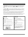
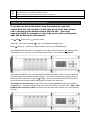
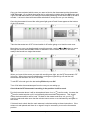
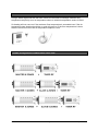
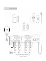
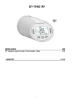
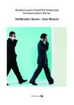
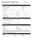
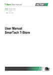
Watts Under Floor Multi-zone Controller User Manual Master unit RF Timer The digital wall thermostat can also use a floor temperature sensor to control minimum and maximum floor temperature, as well as air temperature. Characteristics Wireless communication by radio signal from the RF thermostat to the active antenna and to the RF Timer. Range of approximately 50m in residential environment. 7 day program 9 Built-in programs and 12 User programs Program graphic display Room temperature and time display Auto or Manual (Comfort / Reduced / Anti-freeze) operation Holiday function Reset function Program memory infinite (non volatile) Time kept during 3 hours without power Installation parameters: Prog/easy program, Buzzer Alarm, Pump/Actuator Exercise, ITCS function (Intelligent Temperature Control System), and more. Timer Receiver Display Watts multi-zone controller installation manual Page 1 of 10 Sept 2010 Operating Modes Use and buttons to change the operating mode as shown in the symbols at the top of the screen. If the controller only shows , , , and modes it is in EASY mode and needs changing to PROG mode in the installer settings if you want to access the other modes. In , Auto, or modes, the zone number will be displayed. Use + and – or to change the displayed zone and move the green blinking cursor on the Master/Slave display. If more than one zone is assigned to the same thermostat all those zones will flash at the same time if one of them is selected. Pressing + or – when in Auto mode will take you to another zone where the programmed schedule number P or U will be displayed before the display reverts back to showing the time. In Auto mode the daily schedule will be shown at the bottom of the screen. Holding down the OK button will change the display to show actual temperature for that zone on the left and the actual temperature setpoint of the thermostat assigned to that zone. Use and buttons to change the operating mode Use and buttons to change the operating mode Set clock menu: Reduced operating mode Use this menu to adjust the clock to the actual time. Reduced operating temperature is automatically set to 4ºC less than temperature. Use + and – to adjust the minutes, then press OK = Use + and – to adjust the hours, then press OK Force induced temperature operation indefinitely. Use + and – to adjust the day from 1 to 7, then press OK. Day 1 is whatever you choose it to be, usually Monday. Watts multi-zone controller installation manual comfort -4 C Anti Freeze Operating mode Prevent the system from freezing. Press + and – buttons to adjust the minimum temperature setting for all zones; the maximum setting is 10ºC. Page 2 of 10 Sept 2010 Use and buttons to change the operating mode Use and buttons to change the operating mode Comfort operating mode: Off Mode: When set in this operating mode all the zones will operate in comfort mode although that can be a different temperature for each thermostat. Use this mode if your Heating installation needs to be turned OFF. The RF TIMER will switch off the installation and then switch itself OFF. (blank screen). The controller will provide comfort level temperatures continuously as this mode ignoring any time schedule programmed in. User programs are saved, time is kept running for a few hours. The comfort temperature is whatever is programmed on the thermostat for each zone. Press any key to wake up the RF TIMER. Auto automatic operating mode The controller will follow the timed schedules set for each zone. All zones will be on timed schedules. CAREFUL: If the RF TIMER is stopped, anti-freeze function is also stopped and YOUR INSTALLATION CAN FREEZE IN COLD WEATHER. The temperature will be either at or according to the schedule. P Program menu: When in programming mode, pressing + and – buttons changes the zone indicated by the main number on the display. Press OK and the zone number on left should flash. When the zone number is flashing pressing the and buttons shows the schedule for each day in that zone. The program assigned to that zone will be shown on the right of the display. Zone number Selecting a programmed heat schedule for a zone Watts multi-zone controller installation manual Page 3 of 10 Sept 2010 By pressing OK the program number will start to blink. Now you can change the programmed schedule selected for that zone using the + and – buttons. This will be a P1 to P9 to indicate which one of the 9 pre-programmed schedules is selected or may be a U1 to U12 to indicate which one of the user programmed schedules is to be used. Press OK again and the change will be confirmed. Note: More than one zone can be assigned to one thermostat and all the zones for each thermostat have to use the same schedule. Therefore if for example zones 1 & 2 are assigned to the same RF thermostat, changing the programmed schedule applying to zone 1 will automatically change the schedule for zone 2. Programming User programs (U1 … U12) User programmed heating schedules can be set up and then applied to any zone. Each day of the week can have different schedules within each User programme. Set mode to P, using and buttons. Press OK and the zone number on left should flash. Then press the + key which will increase the zone number at each push until after the last zone the number U1 appears. Continue pushing the + key until you get to the U program you want to set up or edit. Press OK again and the program number stops flashing and you can edit the schedule. The time starts flashing on the right hand side and then this can be altered by either 1. Moving across the indicators at the bottom of the screen, pressing – to set the economy temperature or + to set the comfort temperature. Each time you press - or + the time moves across by 1 hour. 2. Or, move forward and back on the time scale using the and buttons and set the temperature using the + and – buttons as before. Once you have set the schedule for the first day you can move on to the next day by pressing the OK button. If you keep pressing OK this will copy the schedule across to the next day. When you are on day 7 and press the OK button the screen will go back to the first screen of programme mode, showing zone 1 and the programmed schedule that zone 1 is set to. Watts multi-zone controller installation manual Page 4 of 10 Sept 2010 Special functions Holiday function The holiday function will set the boiler to run continuously in number of hours or days. , , or mode for a set To get to the holiday function press the key until you get to P and then press it one more time and you will be in the holiday function. Use the + key to increase the number of hours, up to 24, or number of days if over 24 hours. After setting the hours use and buttons to get to , , or mode. The controller will run in this mode for the set duration and then return to Auto mode. Master and Slave LED Indicators and buzzer Green Lights A green flash indicates a correct radio reception on the zone. A green flashing light is a bit like a cursor, it indicates the zone that will be affected by whatever programming is being done. If the zone is selected for assignment to a thermostat the light will continue flashing until you move off the zone and you can see if the light is permanently on or not. Red lights When the lights are red the relevant zone is being heated, actuator open. Lost thermostat reception alarm When a red light flashes on the Master or Slave unit this indicates that radio reception has been lost for more than 15 minutes. A buzzer will also sound if that is set in installer settings. To clear this signal it is necessary to switch the timer off Watts multi-zone controller installation manual Page 5 of 10 . Sept 2010 Installation Parameters Menu With and buttons, go to mode. Then press OK continuously and press at the same time. You will enter in the installation parameters menu. …next for latest models With and buttons move through the parameters as shown in the table below. Press OK if you want to change a value and then use +/- to change the value and then press OK to save that value. To exit this menu go to the last setting ENd and press OK ….. next for earlier models Use the +/- buttons to move through the parameters and press OK to toggle the setting. Pressing and will take you out of the parameters menu. Factory default settings are underlined. F0 F1 F2 F3 F5 J0 J1 J2 J3 J5 J6 PROG/ EASY Select PROG for complete weekly programmable interface Select EASY for simple interface (only , , , and modes) BUZZ/no Select BUZZ for enabling the alarm sound if a zone is in Lost Thermostat Reception Alarm. NC/NO Actuator Select NC to use the system with Normally Closed actuator valves Select NO to use the system with Normally Open actuator valves Set to NC for the Honeywell actuators supplied by CHNZ. ACtU/no, Actuator Exercise Select ACtU to perform a 5 minute actuator exercise each 12h00 only on the zones that have not been heated for 24 Hours. CHNZ recommends you set this to ACtU to exercise actuators Heating/Heating and Cooling 01 for heating H:C for heating and cooling °C/°F temperature display Select °C for a temperature display in Celsius. Select °F for a temperature display in Fahrenheit. 12h/24h time display Select HH:MMPM for AM/PM clock display. Select HH:MM for 24H clock display. --:15 / --:8 minutes regulation cycle select --:8 minutes only if your installation as fast thermal reacting behavior 2.0°K/ 1.2°K proportional band for regulation select 1.2°K for more precision only if your installation has fast thermal reacting behavior. Beware because selecting 1.2°K can result in a oscillating temperature regulation if the system speed PUMP/no, PUMP exercise Select PUMP to perform a 2 minute pump exercise each day at midday (12:00) but only if the PUMP relay has not been activated for 24 Hours. ItCS/no, Intelligent Temperature Control System Select ItCS to activate the Intelligent Temperature Control System. The Timer RF will learn and start in advance the heating of the zones to assure that the desired temperature is already reached when following the program. Watts multi-zone controller installation manual Page 6 of 10 Sept 2010 Clr ALL rF Init Press OK for 5sec to reset your system: All parameter are reloaded with default values. All RF configurations (Thermostat / Receiver) are erased. Press OK to enter RF initialization mode. See below. Assigning RF Wall Thermostats to Each Zone If you haven’t done this before take the trouble to read and understand this next section, it will save you a lot of time, phone calls, swearing and needless return trips to site. The most important thing to remember is that only zones with a solid green light will be bound to a thermostat. Use and to put unit in (comfort) mode Hold down OK button and push to get into installation settings mode. Press button (or + button for earlier models) until you get to RF init mode Press OK and the zone number will appear on the left of the LCD screen and the zone LED will flash green on zone one, on the left, as shown below. The screen will say 01 Init If you want to bind this zone to a thermostat press the OK button. When you have done this the green light continues and nothing changes. To confirm that the zone is to be bound to a thermostat move the cursor using the button. Now you will see that the LED on the zone to be bound is solid green and the flashing LED moves to the next zone. This stage can be confusing as the LCD screen now says 02 Init and the zone 2 LED is flashing green. This does not mean that zone 2 will be bound to the thermostat – ONLY THE ZONE(S) with solid green LEDs will be bound to the thermostat. Which in the picture below is zone 1. Watts multi-zone controller installation manual Page 7 of 10 Sept 2010 Once you have selected which zones you want to bind to the thermostat put the thermostat in RF init mode. On a digital thermostat this is achieved by holding down the OK button until it goes into RF init mode; on an analogue thermostat switching on the thermostat is all that is needed. It is best to have all thermostats switched off except the one you are binding. Once the thermostat is bound the solid green light goes off and 2 bars appear at the bottom of the LCD screen. Take the thermostat out of RF Init and switch it off before going on to bind the next zone. More than one zone can be allocated to each thermostat, use the and buttons to move through the zones and the OK to select or deselect a zone. Below, zones 1,3 and 4 are ready to be bound to a single thermostat. When you have all the zones you want with a solid green light, put the RF thermostat in RF init mode. When the zones are initialised the solid green lights will go off and the wall thermostat can be taken out of RF init mode. To exit RF init mode go to the last setting ENd and press OK Turn off all other thermostats apart from the one you are setting up. Check that the RF thermostat is working in the position it will be used. Put the thermostat where it will be situated and leave it on in comfort mode. Increase the comfort mode setpoint until it is significantly above ambient temperature. This should cause the thermostat to call for heat. Go back to the master and timer unit, put it in comfort mode and make sure that the relevant zones come on as indicated by red lights on the zones. If it doesn’t work check that the main antenna is sited according to these instructions. If the antenna is well placed and there is no signal it may be necessary to move the thermostat position. Watts multi-zone controller installation manual Page 8 of 10 Sept 2010 Wall thermostats Using a Watts digital wall stat with floor sensor the controller will always maintain floor temperature as priority over air temperature when an external temperature sensor is fitted. So heating will not come on if the maximum floor temperature is exceeded even if the air temperature says heating should be on: and will come on if the floor temperature is lower than the minimum even if the air temperature setpoint is met. Possible Configurations of Mast-Slave-Timer units Watts multi-zone controller installation manual Page 9 of 10 Sept 2010 Watts multi-zone controller installation manual Page 10 of 10 Sept 2010