1
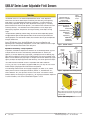
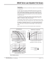
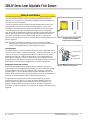
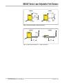
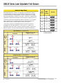
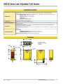
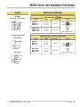
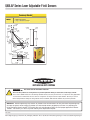
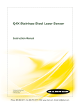
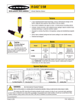
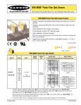
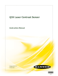
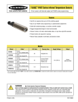
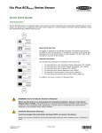
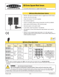
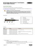
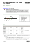
Q60LAF Series Laser Adjustable-Field Sensors
Long-Range Self-Contained Adjustable-Field Laser Sensors
Features
• Long-range adjustable-field background suppression sensor detects objects within
a defined sensing field, and ignores objects located beyond the sensing field cutoff
• Powerful visible red laser sensing beam, class 1 and class 2 models available
• Two-turn, logarithmic cutoff point adjustment for easy setting of cutoff point at long
range; rotating pointer indicates relative cutoff point setting
• Easy push-button or remote setting of light/dark operate and output timing;
continuous status indicators verify all settings at a glance
• Output ON and/or OFF delays adjustable from 8 milliseconds to 16 seconds
• Tough ABS/polycarbonate blend housing is rated IEC IP67; NEMA 6
• Models available for 10-30V dc operation or universal voltage (12 to 250V dc or
24 to 250V ac, 50/60 Hz)
Visible Red, 650 nm
Models
Models
Cutoff
Point
Cable*
Supply
Voltage
Excess Gain
Output
Type
(performance based on 90%
reflectance white test card)
Class 1 Laser
Q60BB6LAF1400
Q60BB6LAF1400Q
Adjustable:
200 mm
Q60BB6LAF1400QP
to
1400 mm
Q60VR3LAF1400
(8" to 55")
Q60VR3LAF1400Q1
5-wire 2 m (6.5')
5-pin Euro-style
QD fitting
1000
10 to 30V dc
5-pin Euro-style
QD pigtail
5-wire 2 m (6.5')
4-pin Micro-style
QD fitting
Universal Voltage
12 to 250V dc
or
24 to 250V ac
Bipolar
NPN/PNP
E/M Relay (SPDT),
N.C. and N.O. contacts
E
X
C
E
S
S
G
A
I
N
at 200 mm
at 1200 mm
100
10
1
10 mm
(0.396")
E/M Relay (SPST),
N.O. contact
100 mm
(3.96")
1000 mm
(39.6")
10000 mm
(396")
DISTANCE
Class 2 Laser
Q60BB6LAF2000
Q60BB6LAF2000Q
Adjustable:
200 mm
Q60BB6LAF2000QP
to
2000 mm
(8" to 80")
Q60VR3LAF2000
Q60VR3LAF2000Q1
5-wire 2 m (6.5')
5-pin Euro-style
QD fitting
����
10 to 30V dc
Bipolar
NPN/PNP
5-pin Euro-style
QD pigtail
5-wire 2 m (6.5')
4-pin Micro-style
QD fitting
Universal Voltage
12 to 250V dc
or
24 to 250V ac
E/M Relay (SPDT),
N.C. and N.O. contacts
E/M Relay (SPST),
N.O. contact
�
�
�
�
�
�
�
�
�
�
�
����������
����������
���
��
�
�����
��������
������
�������
�������
�������
��������
������
��������
* 9 meter cables are available by adding suffix “W/30” to the model number of any cabled sensor (e.g., Q60BB6LAF1400 W/30).
A model with a QD connector requires a mating cable; see page 8.
See Safety Use Warning on back page.
Printed in USA
06/03
P/N 114348
Q60LAF Series Laser Adjustable-Field Sensors
Overview
The Q60LAF sensor is a full-featured adjustable-field sensor. These adjustablefield sensors are able to detect objects of relatively low reflectivity, while ignoring
other objects in the background (beyond the cutoff point). The cutoff distance is
mechanically adjustable, using the 2-turn adjustment screw (Figure 1). A rotating
pointer indicates the relative cutoff position. (The indicator moves clockwise to show
increasing distance.) The collimated laser emitter produces a small, bright spot,
allowing easy alignment and precision sensing of relatively small objects at long
range.
Two push buttons (ON Delay and OFF Delay) are used to set the output delay options,
to toggle between light and dark operate modes and to lock out the push buttons for
security purposes. For 10 to 30V dc models, these functions also may be accomplished
using the remote wire.
Seven LED indicators show, during RUN mode, the sensor configuration and
operating status. During Delay Configuration, 5 of the LEDs combine to form a single
light bar that indicates relative ON or OFF delay time.
������
����������
�����
���������������������
�����������������������
����������������
����������������������
�����������������
�����������������������
������������
��������
�����
��
�����
�
��
�������������������
–
��
�������������
��������
���
�����
���
������������
������������
������������
��������������
Figure 1. Q60LAF features
Cutoff
Distance
Adjustable-Field Sensing – Theory of Operation
In operation, the Q60LAF compares the reflections of its emitted light beam (E) from
an object back to the sensor’s two differently-aimed detectors R1 and R2 (see
Figure 2). If the near detector (R1) light signal is stronger than the far detector (R2)
light signal (see object A, closer than the cutoff distance), the sensor responds to the
object. If the far detector (R2) light signal is stronger than the near detector (R1) light
signal (see object B, object beyond the cutoff distance), the sensor ignores the object.
The cutoff distance for Q60LAF sensors is adjustable from 200 to 1400 mm
(8" to 55") for Class 1 laser models, and 200 to 2000 mm (8" to 80") for Class 2 laser
models. Objects lying beyond the cutoff distance are ignored.
In the drawings and discussion on this page and page 4, the letters E, R1, and R2
identify how the sensor’s three optical elements (Emitter “E”, Near Detector “R1”,
and Far Detector “R2”) line up across the face of the sensor. The location of these
elements defines the sensing axis (see Figure 3). The sensing axis becomes important
in certain situations, such as those illustrated in Figures 7 and 8.
Receiver
Elements
Near
Detector R1
Object B
or
Background
Object
A
Lenses
Far
Detector R2
E
Sensing
Range
Figure 2. Adjustable field sensing concept
Receiver
Elements
Emitter
Sensing
Axis
When an object approaches from the side, the most reliable
sensing usually occurs when the line of approach is parallel
to the sensing axis.
Figure 3. Q60 sensing axis
2
P/N 114348
Banner Engineering Corp. • Minneapolis MN, U.S.A.
www.bannerengineering.com • Tel: 763.544.3164
Q60LAF Series Laser Adjustable-Field Sensors
Color Sensitivity
The effects of object reflectivity on cutoff distance, though small, may be important for
some applications.
The excess gain curves on page 1 were generated using a white test card of 90%
reflectance. Objects with reflectivity of less than 90% reflect less light back to the
sensor, and thus require proportionately more excess gain in order to be sensed
with the same reliability as more reflective objects. When sensing an object of very
low reflectivity, it may be especially important to sense it at or near the distance of
maximum excess gain.
It is expected that at any given cutoff setting, the actual cutoff distance for lower
reflectance targets will be slightly shorter than for higher reflectance targets (see
Figure 4). This behavior is known as color sensitivity.
The percentage of deviation indicates a change in the cutoff point for either 18% gray
or 6% black targets, relative to the cutoff point set for a 90% reflective white test card.
For example, the cutoff point decreases 10% for a 6% reflectance black target when
the cutoff point is adjusted for 1700 mm (67") using a 90% reflectance white test
card. In other words, the cutoff point for the black target is 1530 mm (60") for this
setting.
NOTE: Sensing at closer than the minimum specified range is not guaranteed.
Cutoff Point Deviation
0
300
-1
-2
250
Percent Deviation
-4
-5
-6
-7
-8
-9
-10
-12
200
Class 2
Minimum Range vs. Cutoff Setting*
200
300
Class 1
150
100
50
Minimum Range (mm)
Minimum Range (mm)
Class 1
-3
250
400
600
800 1000 1200 1400 1600 1800 2000
Hysteresis
Class 2
200
150
100
0
200 400
Cutoff Setting (90% White Card)
Hysteresis (% of Cutoff)
Minimum Range vs. Cutoff Setting*
50
600
800
1000 1200 1400 1600 1800 2000
Cutoff Distance (mm) with 90% White Card
0
200 400 600 800 1000 1200 1400 1600 1800 2000
*NOTE: Minimum range is independent of target reflectivity
Cutoff Distance (mm) with 90% White Card
*NOTE: Minimum range is independent of target reflectivity
6.0
Class 1 Laser 18% Gray Card
6% Black Card
4.0
Class 1 Laser 18% Gray Card
Black Card
Class 2 Laser 18% Gray6%
Card
Black
Class 26%
Laser
18%Card
Gray Card
2.0
0
200
6% Black Card
400
600
800 1000 1200 1400 1600 1800 2000
Cutoff Setting (mm) with 90% White Card
Figure 4. Q60LAF performance
Banner Engineering Corp. • Minneapolis MN, U.S.A.
www.bannerengineering.com • Tel: 763.544.3164
P/N 114348
3
Q60LAF Series Laser Adjustable-Field Sensors
Setting the Cutoff Distance
The cutoff distance for Q60LAF sensors may be adjusted between 200 mm and
1400 mm (8" to 55") for Class 1 laser models, and between 200 mm and 2000 mm
(8" to 80") for Class 2 laser models.
Target
To maximize contrast, position the lightest possible background to be used, at the
closest position it will come to the sensor during use (Figure 5). Using a small
screwdriver in the adjustment screw, adjust the cutoff distance until the threshold
is reached and the green Light Sensed indicator changes state. (If the indicator
never comes ON, the background is beyond the maximum sensing cutoff and will be
ignored.) Note the position of the rotating cutoff position indicator at this position.
Then repeat the procedure, using the darkest target, placed in its most distant
position for sensing. Adjust the cutoff so that the indicator is midway between the two
positions (Figure 6).
Background
R1
R2
E
Cutoff
Distance
Figure 5. Set cutoff distance approximately
midway between the farthest
target and the closest background
NOTE: Setting the cutoff distance adjustment screw to its maximum clockwise
position places the receiver lens directly in front of the receiver elements and
results in the Q60 performing as a long-range diffuse sensor.
Increas
ing
For highest sensitivity, the sensor should be mounted so that the target object will be
sensed at or near the point of maximum excess gain. The excess gain curves on page
1 show excess gain vs. sensing distance for 200 mm, 1,200 mm and 2 m cutoffs.
Maximum excess gain for a 200 mm cutoff occurs at a lens-to-object distance of
about 150 mm, and for a 2 m cutoff, at about 500 mm. The background must be
placed beyond the cutoff distance. Following these two guidelines makes it possible to
detect objects of low reflectivity, even against close-in reflective backgrounds.
Di
nce
sta
Sensing Reliabilty
RANGE
ON
DELAY
Farthest Target Object
Set Cutoff Midway
Between
Closest Background
DO
LO
Background Reflectivity and Placement
Avoid mirror-like backgrounds that produce specular reflections. False sensor
response will occur if a background surface reflects the sensor’s light more strongly
to the near detector (R1) than to the far detector (R2). The result is a false ON
condition (Figure 7). Use of a diffusely-reflective (matte) background will cure this
problem. Other possible solutions are to angle either the sensor or the background (in
any plane) so that the background does not reflect back to the sensor.
DELAY
Figure 6.SIG Setting
the cutoff distance
An object beyond the cutoff distance, either moving or stationary (and when
positioned as shown in Figure 8), can cause unwanted triggering of the sensor
because it reflects more light to the near detector than to the far detector. The
problem is easily remedied by rotating the sensor 90° to align the sensing axis
horizontally. The object then reflects the R1 and R2 fields equally, resulting in no false
triggering.
4
P/N 114348
Banner Engineering Corp. • Minneapolis MN, U.S.A.
www.bannerengineering.com • Tel: 763.544.3164
Q60LAF Series Laser Adjustable-Field Sensors
Problem
Solution
Sensing
Field
Core of
Emitted
Beam
Cutoff
Distance
Reflective
Background
Strong
Direct
Reflection
to R1
R1
R2
E
Sensing
Field
Cutoff
Distance
R1
R2
Core of
Emitted
Beam
E
Reflective
Background
E = Emitter
R1 = Near Detector
R2 = Far Detector
E = Emitter
R1 = Near Detector
R2 = Far Detector
Strong
Direct
Reflection
Away From
Receiver
Figure 7. Reflective background – problem and solution
Problem
Solution
Cutoff
Distance
R1
R2
LO
DO
SIG
ON
DELAY
E, R1, R2
RANGE
DELAY
OFF
E
Sensing
Field
Sensing
Field
Figure 8. Object beyond cutoff distance — problem and solution
Banner Engineering Corp. • Minneapolis MN, U.S.A.
www.bannerengineering.com • Tel: 763.544.3164
P/N 114348
5
Q60LAF Series Laser Adjustable-Field Sensors
Setting the Output Delay
Single-Click
Single-Click
Enter
ON-Delay
Setup
+
4.0
72
16
ON
DELAY
+
–
DELAY
OFF
Increase
ON-Delay
56
ON
Decrease
ON-Delay
1.0
DELAY
ON
or
or
>800 ms
Rapid Decrement
>800 ms
Single-Click
ON ON
DELAY
DELAY DELAY
+
–
OFF OFF
DELAY
ON ON
DELAY
DELAY DELAY
–
+
OFF OFF
DELAY
–
ON
DELAY
DELAY +
ON
–
Enable OFF-Delay Increment
Increment
PressRapid
and Hold
Rapid Increment
T >800 ms
+
+
–
T T T >800
ms
Enable OFF-Delay
Increment
+
or
or
–
DELAY
ON
–
T >800 ms
>800 ms
StepT Increment
Step Increment
or
or
>800 ms
>800
ms
Rapid
Increment
Rapid Increment
T T T >800 ms
DELAY
DELAY
OFF
DELAY
DELAY
OFF
Press and Hold
Press and Hold
Press andTHold
T T >800 ms
OFF
OFFDELAY
+
ON
DELAY
DELAY +
–
DELAY
OFF
OFFDELAY
ON
DELAY
+
—
DELAY
Step Increment
Single-Click
Step Increment
Single-Click
Press and Hold
or
or
Step Increment
Rapid Increment
Remote
(DC models only)
Rapid Decrement
Step
Increment
Rapid
Increment
0.04 sec. < T < 0.8 sec.
Single-Click
Single-Click
Single-Click
OFF
Enter
OFF-Delay
Setup
ON
DELAY
+
–
DELAY
OFF
ON
DELAY
–
+
DELAY
OFF
+
–
ON
+
–
T >800 ms
Output OFF-Delay
–or4 second
time-out
>800 ms
T >800 ms
>800 ms
Push Button
ON
–
+
+
ON
–
ON
DELAY
+
–
DELAY
OFF
ON
+
–
DELAY
DELAY
T T T >800
ms
T >800Increment
ms
Enable OFF-Delay
Decrement
Enable OFF-Delay
or Increment
Enable OFF-Delay Decrement
StepTIncrement
Rapid
Increment
Enable
OFF-Delay
T T >800 ms
T >800 ms or
>800 ms
or ms
T T T >800
T T T >800 ms
T >800 ms
>800 ms
Enable OFF-Delay Increment
Step Increment
Rapid Increment
Step Increment
Rapid Increment
Enable OFF-Delay Increment
Step Increment
Rapid Increment
OFF
Increase
OFF-Delay
40
Rapid Decrement
Enable ON-Delay Decrement Step Decrement
Single-Click
Press and Hold
Enable ON-Delay Decrement Step Decrement
ON
Enable Delay Increment
DELAY
T T T >800 ms
–
Enable OFF-Delay Increment
P/N 114348
+
T >800 ms
DELAY
Step Increment
OFF
ON
–
+
DELAY
DELAY
or
T T T >800 ms
T >800 msT T T >800
>800ms
ms
T >800 ms
T T TRapid
>800
ms
T >800
ms
Single-Click
Press and Hold
Enable Delay
Increment
Step
Increment
Increment
Enable OFF-Delay Decrement
or Increment
Enable
OFF-Delay
T T T >800 ms
T >800
ms
>800 ms
Enable OFF-Delay Decrement
Enable OFF-Delay Increment
or
Enable OFF-Delay Increment
Step Increment
Rapid Increment
T >800 ms
>800 ms
OFF
Decrease
OFF-Delay
0.25
Rapid Increment
T T T >800 ms
T >800 ms
T >800 ms
Enable ON-Delay Decrement Step Decrement
Enable ON-Delay Increment
Enable ON-Delay Increment
6
–
DELAY
OFF
ON
DELAY
DELAY
DELAY
Step Increment
Rapid Increment
T T T >800 ms
Rapid Decrement
T >800 ms
T T T
24
Step Decrement
Rapid Decrement
or
>800 ms
Rapid Decrement
DELAY
DELAY
+
–
Step Decrement
OFF
+
ON
DELAY
–
DELAY
or
>800 ms
OFF
ON
DELAY
DELAY
OFF
or
or
0.062
T >800 ms
Rapid Increment
OFF
T >800 ms
+
ON
DELAY
+
–
DELAY
OFF
ON
DELAY
+
–
DELAY
OFF
Press and Hold
Press and Hold
Step Increment
–
ON
DELAY
OFF
DELAY
+
–
DELAY
OFF
Single-Click
Step Decrement
Single-Click
8
Single-Click
Press and Hold
T >800 ms or
>800 ms
T >800 ms
Step Increment
Rapid Increment
or
Single-Click
Press and Hold
Step Increment
Rapid Increment
T >800 ms
or
Enable ON-Delay Increment
Press and Hold
or
T >800 ms
Step Increment
ON
–
DELAY
0.04 sec. < T < 0.8 sec.
Single-Click
No
Delay
Figure 9. ON/OFF Delay options (major
increments depicted)
Step Increment
Rapid Increment
Remote
(DC models only)
Push Button
Single-Click
or
DELAY
ON
+ DELAY
+
OFF –
DELAY
OFF
Output ON-Delay – 4 second time-out
Press and Hold
0
LED Status
DO DO DO DODO
DO DO DO DODO
DO DO DO DODO
DO DO DO DODO
DO DO DO DODO
DO DO
DO DODO
DO
DO
DO
DO
DO
DO
To set a delay, single-click the appropriate button or pulse the remote wire
(DC models only) to enable the process. Then use the + or – button or the
appropriate remote wire pulses to increase or decrease the delay (single-click to
adjust the delay by one step, or hold the button for a rapid increase/decrease).
Delay
Time
(Seconds)
LO LO LO LOLOLO
LO LO LO LOLOLO
LO LO LO LOLOLO
LO LO LO LOLOLO
LO LO LO LOLOLO
LO LO
LO LOLOLO
The Q60LAF output may be delayed from 0.008 to 16 seconds, in 72 increments.
Delay is indicated on the 5-segment light bar using single LED segments or
combinations of them, in varying stages of intensity; see Figure 9.
Step
Number
SIGSIG SIGSIG
SIGSIG SIGSIG
SIGSIG SIGSIG
SIGSIG SIGSIG
SIGSIG SIGSIG
SIGSIG
SIGSIG
SIG
SIG
SIG
SIG
SIG
SIG
SIG
SIG
SIG
SIG
SIG
SIG
When target objects are in motion, an output delay can help prevent “hunting”
or multiple outputs from process control equipment. A delay also can be used
to monitor product flow, “downed goods”, or “jams” (product that is no longer
being conveyed properly). A delay can also create a “smart zone,” enabling certain
equipment to be directly controlled by the sensor, rather than requiring a PLC I/O.
Rapid Increment
Step Decrement
T T T >800 ms
Enable OFF-Delay Decrement
or
T >800 ms
>800 ms
Step Increment
Rapid Increment
Rapid Decrement
Banner Engineering Corp. • Minneapolis MN, U.S.A.
www.bannerengineering.com • Tel: 763.544.3164
Q60LAF Series Laser Adjustable-Field Sensors
Sensor Setup
Light/Dark Operate
Light Operate or Dark Operate mode may be selected using the two push buttons or
triple-click the remote line to toggle between the selections.
Push Button Lockout
For security, the push buttons may be locked out using either the remote line (for
DC models only) or the push buttons themselves. Repeat the process to change the
setting.
Laser Enable/Disable (DC models only)
Laser will be disabled after remote line is held low for 800 ms and will remain disabled
until remote line is released.
NOTE: 500 ms max. delay after laser is enabled; outputs will default to “No Light”
state.
Concurrent Triple-Click
T
ON
–
DELAY
T
+
DELAY
OFF
LO/DO
Toggle
Concurrent Quad-Click
Concurrent
T
T Quad-Click
T
ON
DELAY
–
+
DELAY
OFF
Push Button
Lockout
Toggle
+
–
ON
DELAY
+
–
DELAY
Lasar
Enable/
Disable
ON
DELAY
DELAY
0.04 sec. < T < 0.8 sec.
T
OFF
Banner Engineering Corp. • Minneapolis MN, U.S.A.
www.bannerengineering.com • Tel: 763.544.3164
Concurrent Triple-Click
Remote (DC models only)
OFF
Push Button
T Not
T T Available
T T T T >800 ms
T T T T T T T >800 ms
>800 ms
P/N 114348
7
Q60LAF Series Laser Adjustable-Field Sensors
PROPOSED Q60 LASER CLICHES
Laser Classifications
Class 1
�������
�������������
Lasers that are safe under reasonably foreseeable conditions of
operation, including the use of optical instruments for intrabeam
viewing. Reference 60825-1 Amend. 2 ©
IEC:2001(E), section 8.2.
�����������
���������������������������
�������������������������
�����������������������������
��������������������������
�����������������������������
�����������������������������
Class 2
�
����������������������������������
���������������������������
������������������������
�������������������
PROPOSED Q60 LASER CLICHES
��������
���������
��������
���������������������
��������������������������
����������������������������������
�����������������������������������
Lasers that emit visible radiation in the wavelength range from
400 nm to 700 nm where eye protection is normally afforded by
aversion responses, including the blink reflex. This reaction may
be expected to provide adequate protection under reasonably
foreseeable conditions of operation, including the use of optical
instruments for intrabeam viewing.
�������������
���������
CLASS 1 LASER PRODUCT
�����������������������������
����������������������������������
���������������������������������������
��������
����������������������
Reference 60825-1 Amend. 2 © IEC:2001(E), section 8.2.
�������
�������������
��������
�������
���������������������������
�������������������������
�����������������������������
��������������������������
�����������������������������
�����������������������������
CLASS 1 LASER PRODUCT
�����������������������������
����������������������������������
���������������������������������������
��������
������������
����������������������������������
���������������������������
������������������������
�������������������
���������������������
��������������������������
����������������������������������
�����������������������������������
�������������
���������
�������
�������
Figure 10.����������������������
Laser aperture location
Class 2 Laser Safety Notes: Low-power lasers are, by definition,
incapable of causing eye injury within the duration of the blink
(aversion response) of 0.25 seconds. They also must emit only visible wavelengths
(400 - 700 nm). Therefore, an ocular hazard can exist only if an individual overcomes
their natural aversion to bright light and stares directly into the laser beam.
For safe laser use:
• Do not permit a person to stare at the laser from within the beam.
• Do not point the laser at a person’s eye at close range.
�
�
• Terminate the beam emitted by a Class 2 laser product at the end of its useful path.
Locate open laser beam paths either above or below eye level, where practical.
!
Caution
Use of controls or adjustments or performance of
procedures other than those specified
herein may result in hazardous radiation
exposure; per EN 60825.
Do NOT attempt to disassemble this
sensor for repair. A defective unit must
be returned to the manufacturer.
�
�
8
P/N 114348
Banner Engineering Corp. • Minneapolis MN, U.S.A.
www.bannerengineering.com • Tel: 763.544.3164
Q60LAF Series Laser Adjustable-Field Sensors
Specifications
Supply Voltage and
Current
Q60BB6LAF models: 10 to 30V dc (10% maximum ripple) at less than 35 mA exclusive of load
Q60VR3LAF Universal models: 12 to 250V dc or 24 to 250V ac, 50/60 Hz
Input power 1.5 W maximum
Supply Protection
Protected against reverse polarity and transient voltages
(Q60VR3 models’ dc hookup is without regard to polarity)
Output Configuration
Q60BB6LAF models: Bipolar; one NPN (current sinking) and one PNP (current sourcing) open-collector
transistor
Q60VR3LAF cabled model: E/M Relay (SPDT), normally closed and normally open contacts
Q60VR3LAFQ1 (QD) model: E/M Relay (SPST), normally open contact
Q60BB6LAF models
150 mA maximum each output @ 25° C
Off-state leakage current: < 5µA @ 30V dc
Output saturation NPN: < 200 mV @ 10 mA and < 1V @150mA
Output saturation PNP: < 1V at 10 mA; < 1.5V at 150 mA
Output Rating
Q60VR3LAF Universal models
Min. voltage and current: 5V dc, 10 mA
Mechanical life of relay: 50,000,000 operations
Electrical life of relay at full resistive load: 100,000 operations
Max. switching power (resistive load): Cabled models: 1250VA, 150 W
QD models: 750VA, 90W
Max. switching voltage (resistive load): Cabled models: 250V ac, 125V dc QD models: 250V ac, 125V dc
Max. switching current (resistive load):
Cabled models: 5 A @ 250V ac, 5 A @ 30V dc derated to 200 mA @ 125V dc
QD models: 3 A @ 250V ac, 3 A @ 30V dc derated to 200 mA @ 125V dc
Output Protection
Circuitry
Q60BB6LAF models: Protected against continuous overload or short circuit of outputs
All models: Protected against false pulse on power-up
NOTE: 1 second max. delay at power up (outputs do not conduct during this time).
Output Response Time
Q60BB6LAF models: 2 milliseconds ON and OFF
Q60VR3LAF Universal models: 15 milliseconds ON and OFF
Repeatability
500 microseconds
Sensing Hysteresis
See Figure 4.
ON Green: RUN mode, ON-delay active
Flashing Green: ON-Delay Selection mode
OFF-Delay
ON Green: RUN mode, OFF-delay active
Flashing Green: OFF-Delay Selection mode
5-Segment Light Bar*
ON/OFF-Delay Selection: Indicates relative delay time
RUN Mode:
Output
ON Yellow: Outputs are conducting
ON Green: ON/OFF-Delay Selection
Dark Operate
ON Green: Dark Operate selected
Lockout
ON Green: Buttons locked out
Light Operate
ON Green: Light Operate selected
Signal
ON Green: Sensor receiving signal
Flashing Green: Marginal signal (1.0 to 2.25 excess gain)
ON-Delay
Indicators (see Figure 1)
NOTE: Outputs are
active during
on/off timing
selection mode.
Laser Characteristics
Spot Size: approximately 4 x 2 mm throughout range (collimated beam)
Angle of Divergence: 5 milliradians
NOTE: Contact factory for custom laser spot size.
Banner Engineering Corp. • Minneapolis MN, U.S.A.
www.bannerengineering.com • Tel: 763.544.3164
P/N 114348
9
Q60LAF Series Laser Adjustable-Field Sensors
Specifications, continued
Adjustments
Slotted, geared, 2-turn, cutoff range adjustment screw (mechanical stops on both ends of travel)
2 momentary push buttons: ON-Delay (+) and OFF-Delay (–) (DC models also have remote program wire)
ON-Delay select: 8 ms to 16 seconds
OFF-Delay select: 8 ms to 16 seconds
LO/DO select
Push button lockout for security
Laser Enable/Disable (remote wire only)
Construction
Housing: ABS/polycarbonate Window: Acrylic
Environmental Rating
IEC IP67; NEMA 6
Connections
Q60BB6LAF (DC) models: 2 m (6.5') or 9 m (30') attached cable, 5-pin Euro-style integral QD fitting, or
5-pin Euro-style 150 mm (6") QD pigtail
Q60VR3LAF Universal models: 2 m (6.5') or 9 m (30') attached cable, or 5-pin Micro-style 150 mm (6") QD
fitting
Operating Conditions
Temperature:
Q60BB6LAF (DC) models: -10° to +50°C (+14° to 121°F)
Q60VR3LAF Universal models: -10° to +45°C (+14° to 113°F)
Maximum Relative Humidity: 90% at 50°C (non-condensing)
Dimensions
15.2 mm
(0.60")
4.0 mm
(0.16")
4.9 mm 4.0 mm
(0.19") (0.16")
–
DELAY
OFF
+
M3 hardware is included:
2 screws (M3 x 0.5 x 30 ppms)
2 hex nuts
2 lock washers
SIG
LO
ON
DELAY
DO
25.0 mm
(0.98")
RANGE
60.0 mm
(2.36")
52.0 mm
(2.05")
2x ø4.2
mm
(0.17")
14.0 mm
(0.55")
Q60BB6AFV200
52.0 mm
(2.05")
75.0 mm
(2.95")
Q60BB6AFV200Q
67.0 mm
(2.64")
17.0 mm
(0.67")
77.6 mm
(3.06")
10
P/N 114348
Banner Engineering Corp. • Minneapolis MN, U.S.A.
www.bannerengineering.com • Tel: 763.544.3164
Q60LAF Series Laser Adjustable-Field Sensors
Hookups
Quick-Disconnect (QD) Cables
DC Models
(Cabled, QD, and QP Models)
5-pin Euro-style – DC Models
bn
+
10-30V dc
–
bu
wh
bk
Load
Model
Length
Connector
Pin-out
White Wire
MQDC1-506
MQDC1-515
MQDC1-530
2 m (6.5')
5 m (15')
9 m (30')
Straight
MQDC1-506RA
MQDC1-515RA
MQDC1-530RA
2 m (6.5')
5 m (15')
9 m (30')
Right-angle
Brown Wire
Blue Wire
Black Wire
Gray Wire
Load
gy
Remote Configure
Universal Voltage Models
(Cabled Models)
bn
AC/DC
bu
wh
NC
ye
(cable connector shown)
4-pin Micro-style – Universal Voltage Models
Model
MQAC-406
MQAC-415
MQAC-430
Length
Connector
2 m (6.5')
5 m (15')
9 m (30')
Straight
NO
5A max. load
(QD Models)
Green Wire
Red Wire
Red/White
Wire
C
bk
Pin-out
MQAC-406RA
MQAC-415RA
MQAC-430RA
2 m (6.5')
5 m (15')
9 m (30')
Red/Black
Wire
Right-angle
(cable connector shown)
rd/bk
rd/wh
rd
gn
AC/DC
NO
C
3A max. load
Banner Engineering Corp. • Minneapolis MN, U.S.A.
www.bannerengineering.com • Tel: 763.544.3164
P/N 114348
11
Q60LAF Series Laser Adjustable-Field Sensors
Accessory Bracket
SMBQ60
8.0 mm
(0.31")
4.0 mm
(0.16")
• Right-angle bracket
• 14-ga., 304 Stainless Steel
11.0 mm
(0.43")
20.0 mm
(0.79")
4.0 mm
(0.16")
ø3.8 mm
(0.15")
1.9 mm
(0.75")
58.0 mm
(2.28")
R84.8 mm
(3.34")
15.0 mm
(0.59")
8.0 mm
(0.31")
82.0 mm
(3.23")
19.0 mm
(0.75")
3°
4.0 mm
(0.16")
6°
37.8°
10.0 mm
(0.39")
4.2 mm
(0.17")
ø4.5 mm
(0.18")
R24.1 mm
(0.95")
10.0°
5.0°
2x R2.25 (0.88")
32.0 mm
(1.26")
64.0 mm
(2.52")
!
WARNING . . .
Not To Be Used for Personnel Protection
Never use these products as sensing devices for personnel protection. Doing so could lead to serious injury or death.
These sensors do NOT include the self-checking redundant circuitry necessary to allow their use in personnel safety applications.
A sensor failure or malfunction can cause either an energized or de-energized sensor output condition. Consult your current
Banner Safety Products catalog for safety products which meet OSHA, ANSI and IEC standards for personnel protection.
WARRANTY: Banner Engineering Corp. warrants its products to be free from defects for one year. Banner Engineering Corp.
will repair or replace, free of charge, any product of its manufacture found to be defective at the time it is returned to the
factory during the warranty period. This warranty does not cover damage or liability for the improper application of Banner
products. This warranty is in lieu of any other warranty either expressed or implied.
P/N 114348
Banner Engineering Corp., 9714 Tenth Ave. No., Minneapolis, MN 55441 • Phone: 763.544.3164 • www.bannerengineering.com • Email: [email protected]