1
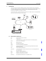
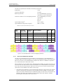
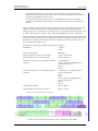
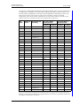
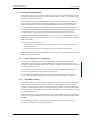
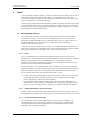
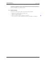
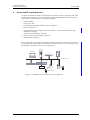
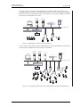
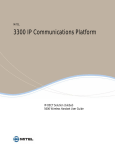
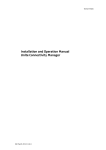
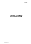
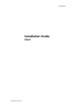
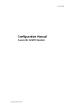
TD 92313GB
System Description
Ascom VoWiFi System
13 December 2010 / Ver. F
System Description
Ascom VoWiFi System
TD 92313GB
Contents
1 Introduction .................................................................................................................... 1
1.1 Abbreviations and Glossary................................................................................................... 1
2 WLAN............................................................................................................................... 5
2.1 WLAN Infrastructure ............................................................................................................... 5
2.1.1 Autonomous Access Points ......................................................................................... 5
2.1.2 Controller-Based Access Points .................................................................................. 6
2.2 RF Modulation Standard......................................................................................................... 6
2.2.1 802.11b/g RF Modulation Standard......................................................................... 6
2.2.2 802.11a RF Modulation Standard ............................................................................. 7
2.2.3 802.11n RF Modulation Standard ............................................................................. 8
2.3 Access Control and Security ............................................................................................... 11
2.3.1 ESSID (Extended Service Set Identifier)................................................................. 11
2.3.2 MAC Address Filtering................................................................................................ 11
2.3.3 WEP................................................................................................................................. 12
2.3.4 WPA™............................................................................................................................. 12
2.3.5 WPA2™ .......................................................................................................................... 12
2.3.6 Proactive Key Caching (Opportunistic Key Caching) .......................................... 13
2.3.7 Certificate-based authentication ............................................................................ 13
2.4 Quality of Service (QoS)....................................................................................................... 14
2.4.1 802.11e ......................................................................................................................... 14
2.4.2 WMM™ (WME™).......................................................................................................... 14
2.4.3 TSPEC Call Admission Control ................................................................................... 15
2.4.4 WMM™ Power Save .................................................................................................... 15
2.5 Cisco Compatible Extensions (CCX)................................................................................... 15
2.6 802.11h................................................................................................................................... 15
3 VoWiFi ........................................................................................................................... 16
3.1 VoIP Signalling Protocols..................................................................................................... 16
3.1.1 H.323.............................................................................................................................. 16
3.1.2 H.450 Supplementary Services for H.323 ............................................................ 16
3.1.3 Session Initiation Protocol (SIP) .............................................................................. 16
3.2 VoWiFi Standards.................................................................................................................. 17
4 Ascom VoWiFi System Overview................................................................................. 18
4.1 Supported Standards ........................................................................................................... 20
4.1.1 Ascom i62 VoWiFi Handset ...................................................................................... 20
4.1.2 Ascom i75 VoWiFi Handset ...................................................................................... 20
4.2 System Functions .................................................................................................................. 21
4.3 WLAN Functions .................................................................................................................... 21
4.3.1 Roaming......................................................................................................................... 21
13 December 2010 / Ver. F
System Description
Ascom VoWiFi System
TD 92313GB
4.3.2 Association.................................................................................................................... 22
4.3.3 User Authentication ................................................................................................... 22
4.4 Network Parameter Download .......................................................................................... 23
4.5 Supported Third-Party Products ....................................................................................... 23
4.6 WLAN Planning and Deployment for Ascom VoWiFi System .................................... 23
5 Ascom VoWiFi System Components ........................................................................... 24
5.1 Ascom VoWiFi Handsets...................................................................................................... 24
5.1.1 Ascom i62 VoWiFi Handset ...................................................................................... 24
5.1.2 Ascom i75 VoWiFi Handset ...................................................................................... 24
5.2 Access Point (AP) .................................................................................................................. 25
5.3 Controller ................................................................................................................................. 25
5.4 RADIUS Server ........................................................................................................................ 25
5.5 Integrated Wireless Messaging and Services (IMS2)................................................... 25
5.6 Unite Connectivity Manager (UniteCM)........................................................................... 27
5.7 Portable Device Manager Windows Version (WinPDM) .............................................. 27
5.8 VoIP Gateway/Gatekeeper.................................................................................................. 28
5.9 SIP Proxy Server..................................................................................................................... 28
6 Administration Tools ................................................................................................... 29
7 Connection to Other Systems ...................................................................................... 30
7.1 System Solution when connected to IP-PBX .................................................................. 30
7.2 System Solution when connected to Traditional PBX.................................................. 31
8 Related Documents ...................................................................................................... 32
9 Document History ........................................................................................................ 33
Appendix A: Ascom Technical Documentation ............................................................. 34
13 December 2010 / Ver. F
System Description
Ascom VoWiFi System
1
TD 92313GB
Introduction
The Ascom Voice over Wireless Fidelity (VoWiFi) system provides wireless IP telephony,
messaging and alarm functions to enterprise LANs. Using third-party WLAN products as well
as in-house developed hardware and software, the system enables data and voice
transmission together with seamless roaming.
This document gives a general description of the Ascom VoWiFi solution. It briefly describes
WLAN and VoWiFi technologies and standards.
Figure 1.
Access Point
VoWiFi Handsets
Controller
Location Server
IMS2/
Unite CM
LAN
Presence
Management
System
Unite System
IP-PBX
required equipment
optional equipment
Figure 1. VoWIFI overview
1.1
Abbreviations and Glossary
AES
Advanced Encryption Standard
AP
Access Point:
a radio transceiver providing LAN connection to wireless devices.
BPSK
Binary Phase-Shift Keying
BSS
Basic Service Set
CAC
Call Admission Control
CCKM
Cisco Centralized Key Management
CCMP
Counter Mode Cipher Block Chaining-Message Authentication Code
(CBC-MAC) protocol
CCX
Cisco Compatible Extensions
Controller
a Controller delivers Wireless LAN services over an existing Ethernet or
IP infrastructure.
DFS
Dynamic Frequency Selection
DTIM
Delivery Traffic Indication Message
EAP
Extensible Authentication Protocol
EAP-FAST
EAP-Flexible Authentication via Secured Tunnel
13 December 2010 / Ver. F
1
System Description
Ascom VoWiFi System
TD 92313GB
EAP-TLS
EAP-Transport Layer Security
ESS
Enhanced System Service:
Unite modules that handle centralised number planning, remote
connection, system supervision, fault handling, group handling,
message routing, centralised logging, activity logging, and user access
administration.
ESSID
Extended Service Set Identifier
ETSI
European Telecommunications Standards Institute:
a European standards organization charged with defining standards
for EC countries.
FCC
Federal Communications Commission (FCC):
the primary interstate regulatory authority for telecommunications
and radio systems for the US.
FEC
Forward Error Correction
GI
Guard Interval
Handover
The process of moving a handset from one AP to another during an
ongoing call.
IEEE
Institute of Electrical and Electronics Engineers
IETF
Internet Engineering Task Force
IMS2
Integrated Wireless Messaging and Services:
Unite module that enables wireless services to and from the VoWiFi
handsets in a WLAN system. It also includes the Device Manager.
IP
Internet Protocol:
a global standard that defines how to send data from one device to
another over the wired and wireless media.
ISM
Industrial Scientific Medical
ITU
International Telecommunications Union
Jitter
Variation in latency among a group of packets sent between two
nodes.
Latency
The total time for a data frame to travel from a sender to a receiver.
MAC address
Medium Access Control address:
a unique identifier attached to most forms of computer networking
equipment.
MCS
Modulation and Coding Scheme
MIMO
Multiple-Input, Multiple-Output
Multipath
The receiver does not only contain a direct line-of-sight radio wave, but
also a larger number of reflected radio waves.
PEAP-MSCHAP
Protected Extensible Authentication Protocol-Microsoft Challenge
Handshake Authentication Protocol.
PBX
Private Branch Exchange:
telephone system within an enterprise.
PRI
Primary Rate Interface
PTT
Push-To-Talk
QAM
Quadrature Amplitude Modulation:
16-QAM has 16 possible signal states with each symbol representing
4 bits. 64-QAM has 64 possible signal states with each symbol
representing 6 bits.
13 December 2010 / Ver. F
2
System Description
Ascom VoWiFi System
TD 92313GB
QoS
Quality of Service:
defines to what extent transmission rates, error rates etc. are
guaranteed in advance.
QPSK
Quadrature Phase-Shift Keying
RADIUS
Remote Authentication Dial-In User Service:
a standard protocol for authentication servers.
RF
Radio Frequency
Roaming
The process of moving a handset from one AP to another when moving
within the network.
RSVP
Resource Reservation Protocol:
a QoS signalling protocol that nails down a channel through an IP
network based on the session ID.
RTCP
Real-Time Control Protocol
RTP
Real-Time Protocol
RTSP
Real-Time Streaming Protocol
SAP
Session Announcement Protocol,
SDP
Session Description Protocol
SIP
Session Initiation Protocol
SOHO
Small Office/Home Office
TDMA
Time Division Multiple Access
TPC
Transmit Power Control
TSPEC
Traffic Specification
UNII
Unlicensed National Information Infrastructure
Unite
Ascom messaging platform. A generic term for a messaging system
that unites different systems, for example System 900, System 9d, and
VoWiFi.
Unite CM
Unite Connectivity Manager:
Unite module that enables messaging and alarm handling in a WLAN
system. It also includes the Device Manager.
VoIP
Voice over Internet Protocol:
the technology used to transmit voice conversations over IP.
VoWiFi
Voice over Wireless Fidelity:
a wireless version of VoIP and refers to IEEE 802.11a, 802.11b,
802.11g, or 802.11n network.
WEP
Wired Equivalent Privacy encryption keys:
the original security standard used in wireless networks to encrypt the
wireless network traffic.
WiFi
WiFi is a term developed by the Wi-Fi Alliance®a to describe wireless
local area network (WLAN) products that are based on the Institute of
Electrical and Electronics Engineers' (IEEE) 802.11 standards. Today,
most people use WiFi as a reference to wireless connectivity.
WinPDM
Portable Device Manager Windows Version:
a software application for initial configuration of the VoWiFi handsets.
WLAN
Wireless Local Area Network (LAN):
a type of LAN in which data is sent and received via high-frequency
radio waves rather than cables or wires.
13 December 2010 / Ver. F
3
System Description
Ascom VoWiFi System
TD 92313GB
WMM™
Wi-Fi Multimedia™:
offers QoS functionality for WiFi networks.
WPA™
Wi-Fi Protected Access™:
a set of security features for wireless networks based on IEEE 802.11i.
WPA2™
Wi-Fi Protected Access 2™:
adds additional security features, the most important of which are preauthentication, which enables secure fast roaming, and AES, which is
the new FIPS standard for data encryption.
a.) The Wi-Fi Alliance® develops universal specifications, facilitates testing, and grants
interoperability certification for Wi-Fi equipment from a wide range of manufacturers across
product lines.
13 December 2010 / Ver. F
4
System Description
Ascom VoWiFi System
2
TD 92313GB
WLAN
A Wireless Local Area Network (WLAN) uses radio frequency (RF) technology to transmit
and receive data over the air. To enable transmission of such different types of
communication as data and voice, it is essential that hardware and software comply to
specified standards. The Institute of Electrical and Electronics Engineers (IEEE) have
established the IEEE 802.11 standard, which is the most used WLAN standard of today. The
original version was released in 1997 and over the years several amendments have been
added, for example, IEEE 802.11a, IEEE 802.11b, IEEE 802.11g, and IEEE 802.11n. Most of
these were merged with the base standard in 2007 except IEEE 802.11n, which is a more
recent amendment.
See section 4.1 Supported Standards for a description of the 802.11 amendments
supported by the Ascom VoWiFi system.
2.1
WLAN Infrastructure
There are two types of WLAN topologies: the Ad-Hoc mode and the Infrastructure Mode. The
Ad-Hoc mode provides peer-to-peer connectivity where two clients communicate directly
with each other via their WLAN cards. The Infrastructure Mode, on the other hand, is used to
incorporate the wireless clients into an existing wired LAN infrastructure.
In the Infrastructure Mode all communication is passed through the Access Points (APs) that
are connected to the wired LAN. A single AP communicating with a number of clients is
called a Basic Service Set (BSS). A number of interconnected APs with the same network
name is called an Extended Service Set.
The AP is basically a radio transmitter/receiver but, depending on hardware and software, it
can be more or less intelligent. An AP that holds information about the mobile clients
authorized to enter the system is called an autonomous AP (or “fat” AP), whereas an AP
that only is responsible for forwarding received data, is called a controller-based AP (or
“thin” AP). While the autonomous APs carry out all wired to wireless packet format
conversion, encryption, QoS application, and RF statistics monitoring, the very thinnest APs
pass all of this to their central controller, and act basically just as a media converter.
2.1.1
Autonomous Access Points
Figure 2.
LAN
AP
AP
AP
Figure 2. Autonomous APs connected directly to the LAN.
The example in figure 2 shows a system with autonomous APs. This is the most basic type
of a WLAN in Infrastructure Mode. The individual autonomous APs handle all traffic
handling, authentication, RF management, and mobility functions. They are entirely
independent of each other, and have to be configured separately.
13 December 2010 / Ver. F
5
System Description
Ascom VoWiFi System
2.1.2
TD 92313GB
Controller-Based Access Points
Figure 3.
001
Centralized Wireless Management
Controller
Controller
LAN
AP
AP
AP
Figure 3. Controller-based APs with centralized management.
The example in figure 3 shows a system with controller-based APs. With this approach, APs
can share the features that enhance wireless communications. Much of the configuration is
centralized in the Controller. The Controller handles switching functionality to the WLAN,
security functionality, RF management, QoS, and extended roaming features. It is physically
connected to the LAN and not to the APs.
It is also possible to use a Controller that incorporates a switch. The APs are then directly
connected to the Controller and are basically just a radio and an antenna. The Controller
handles most of the MAC layer all by itself.
The use of controller-based APs enhances operation of the VoWiFi system, makes
centralized administration over the WLAN possible, and makes it easy to expand the
network. If several Controllers are used in a system, a centralized intelligent server
(Centralized Wireless Management) can be used for administration and management.
2.2
RF Modulation Standard
2.2.1
802.11b/g RF Modulation Standard
WLAN products based on the 802.11b/g standards operate in the 2.400 to 2.497 GHz
frequency range, which is one of the Industrial Scientific Medical (ISM) bands.This is an unlicensed frequency band also used by Bluetooth devices, medical equipment, and many
other devices that do not require a license.
The frequency band is divided into channels on which data packets are sent in parallel. It is
important that the channels do not overlap each other as this would decrease the
performance of the network.
APs supporting the 802.11b/g standard have up to 14 channels with centre frequencies
that are 5 MHz apart (applies to channel 1 to 13)1. Since the bandwidth of each channel is
either 22 MHz (802.11b) or 20 MHz (802.11g), the centre frequencies for non-overlapping
channels must be at least 25 MHz apart. This gives us three non-overlapping channels at the
most, see the example with 11 channels in figure 4. These channels are reused and allocated
to APs in different regions, one channel per AP.
Use of other channels than 1, 6 and 11 will have a major negative impact on performance in
the system since those channels will interfere with each other. Not only due to RF
interference, but also due to the 802.11 protocol specification, a selection of channels other
than 1, 6 and 11 will cause a performance reduction.
1.The centre frequency in channel 14 differs from the other (12 MHz apart). It was previously used only in Japan.
13 December 2010 / Ver. F
6
System Description
Ascom VoWiFi System
TD 92313GB
The 802.11b and 802.11g specifications include the following restrictions:
Radio Band:
2.4 GHz
Maximum Data Rate:
11 Mbps (802.11b)
54 Mbps (802.11g)
Operating channels:
1–14 (depending on country
regulations)
ETSI: 1–13
FCC: 1–11
Maximum number of non-overlapping channels:
a
3
Typical Indoor Range :
30 m / 100 ft
Typical Outdoor Range (Line of Sight)a:
120 m / 400 ft
a.With basic antenna and maximum power level.
Figure 4. The 2.4 GHz band with three non-overlapping channels (1, 6 and 11).
The standard specifies data rates up to 11 Mbps for 802.11b and 54 Mbps for 802.11g, but
this must be considered as a theoretical maximum, only available within a limited distance
from an AP. More resilient coding schemes are needed to decode signals with lower strength
at the expense of data rate. Also, note that this is the maximum data rate, which means that
the maximum throughput is more likely to be half of that because of data headers etc.
As a client moves away from the AP, data rate is reduced, and consequently the throughput.
The average throughput is, as a rule of thumb, half of the data rate. Therefore it is important
that APs are not placed too far apart.
2.2.2
802.11a RF Modulation Standard
WLAN products based on the 802.11a standard operate in the 5 GHz frequency range. This
is an unlicensed frequency band called the Unlicensed National Information Infrastructure
(UNII) band. It is divided into the UNII-1 band (5.15–5.25 GHz), the UNII-2 band (5.25–
5.35 GHz), the UNII-2 Extended band (5.47–5.710 GHz), and the UNII-3 band (5.725–
5.825 GHz) (depending on country regulations).
The UNII band is divided into 23 non-overlapping channels (depending on country
regulations) with a bandwidth of 20 MHz. The centre frequencies are 20 MHz apart.
Originally the UNII-1 band was intended for indoor operation, the UNII-3 band for outdoor
operation, and the UNII-2 and UNII-2 Extended band for both indoor and outdoor operation.
This distinction has been removed for FCC. For ETSI the UNII-1 and UNII-2 bands are still
intended for indoor operation, and the UNII-2 Extended band for both indoor and outdoor
operation. Also, the maximum power levels are lower for ETSI than FCC. The UNII-2 band’s
primary users are radar and satellite systems. To avoid interference, all unlicensed
transmitters operating in the UNII-2 band must be able to detect the presence of radar
signals and to dynamically and automatically change to a different transmit frequency if
radar is discovered, see section 2.6 802.11h on page 15.Therefore, it is not recommended to
use these bands for voice traffic.
Above the UNII band there is a small part of the ISM band that can be used by 802.11a
products as well (5.825–5.875 GHz).
13 December 2010 / Ver. F
7
System Description
Ascom VoWiFi System
TD 92313GB
The 802.11a specification includes the following restrictions:
Radio Band:
5 GHz
Maximum Data Rate:
54 Mbps
Operating channels:
36–165 (depending on country
regulations), see the table below
Maximum number of non-overlapping channels:
19–24 (depending on country
regulations)
ETSI: 19
FCC: 24
Typical Indoor Rangea:
30 m / 100 ft
Typical Outdoor Range (Line of Sight)a:
100 m / 330 ft
a.With basic antenna and maximum power level.
Radio
band
Frequency
Number of Channel numbers
range (GHz) channels
FCC
ETSI
UNII-1
5.15–5.25
4
36, 40, 44, 48
X
X
UNII-2
5.25–5.35
4
52, 56, 60, 64
X
X
UNII-2
Extended
5.47–5.710
11
100, 104, 108, 112, 116, 120, X
124, 128, 132, 136, 140
X
UNII-3
5.725–5.825 4
149, 153, 157, 161
X
ISM
5.825–5.875 1
165
X
Figure 5. The UNII band with 24 non-overlapping channels
2.2.3
802.11n RF Modulation Standard
The 802.11n standard improves the reliability of communications, the predictability of
coverage, and the overall throughput. It uses the same frequency bands as 802.11b/g and
802.11a. This means that WLAN products based on the 802.11n standard can operate in
the 2.4 GHz band, the 5 GHz band, or both.
802.11n devices can use Multiple-Input, Multiple-Output (MIMO). This means that they can
use more than one radio chain to transmit and receive. The standard defines configurations
from one transmit and one receive radio chain (1x1) up to four transmit and four receive
radio chains (4x4). MIMO can be used in several ways:
•
Spatial division multiplexing: A transmitter breaks down the signal stream into multiple
streams, and transmits the streams using multiple antennas spaced a short distance
apart. This creates a difference in the multipath images for each stream. The receiver can
therefore distinguish the individual streams and put them back together, thereby
increasing the overall data rate of the system.
13 December 2010 / Ver. F
8
System Description
Ascom VoWiFi System
•
•
TD 92313GB
Space-time block coding: A transmitter uses more antennas than signal streams to
redundantly transmit the transmit signal. This increases the reliability of the signal at
the receiver, and reduces the error rate.
Transmit beamforming: A transmitter uses multiple antennas to focus the signal
strength in the direction of the receiver. This increases the signal-to-noise ratio at the
receiver.
802.11n devices can use either 20 MHz or 40 MHz channels. The 40 MHz channels are two
adjacent 20 MHz channels that are bonded together, thereby more than doubling the
effective data rate. It is possible to have one to two non-overlapping 40 MHz channel in the
2.4 GHz band, and nine to eleven in the 5 GHz band, depending on country regulations.
802.11n devices have the option of using a short Guard Interval (GI). GI is the period of time
in between symbols, and are used to reduce the interference between symbols. 802.11a/b/
g devices use a GI that is 800 ns long, but 802.11n devices have the option of using a GI
that is either 800 or 400 ns long.
The 802.11n specification includes the following restrictions:
Radio Band:
2.4 GHz
5 GHz
Maximum Data Rate:
600 Mbps
Operating channels in the 2.4 GHz band:
Same as 802.11b/g
Operating channels in the 5 GHz band:
Same as 802.11a
Maximum number of non-overlapping 20 MHz
channels:
2.4 GHz band: 3
5 GHz band: 19–24 (depending on
country regulations)
ETSI: 19
FCC: 24
Maximum number of non-overlapping 40 MHz
channels:
2.4 GHz band: 1–2 (depending on
country regulations)
ETSI: 2
FCC: 1
5 GHz band: 9–11 (depending on
country regulations)
ETSI: 9
FCC: 11
Typical Indoor Rangea:
30 m / 100 ft
a
Typical Outdoor Range (Line of Sight) :
100 m / 330 ft
a.With basic antenna and maximum power level.
Figure 4. .
Figure 6. 20 MHz and 40 MHz channels in the 2.4 GHz and 5 GHz bands
13 December 2010 / Ver. F
9
System Description
Ascom VoWiFi System
TD 92313GB
The 802.11n standard defines Modulation and Coding Scheme (MCS), which is combinations
of modulation, Forward Error Correction (FEC) coding, and number of spatial streams. The
maximum data rate depends on the MCS, channel bandwidth, and GI length. There are 77
MCS values from 0 to 76. The first 32 MCSs are shown below. The rest are mixed
combinations that can be used to modulate two to four streams. 802.11n stations must
support values 0–7, and 802.11n APs must support MCS values 0–15.
MCS
Index
Number of Modulation and
streams
FEC Coding
Data Rate (Mbps)
20 MHz Channel
Data Rate (Mbps)
40 MHz Channel
GI=800 ns GI=400 ns GI=800 ns GI=400 ns
0
1
BPSK 1/2
6.50
7.20
13.50
15.00
1
1
QPSK 1/2
13.00
14.40
27.00
30.00
2
1
QPSK 3/4
19.50
21.70
40.50
45.00
3
1
16-QAM 1/2
26.00
28.90
54.00
60.00
4
1
16-QAM 3/4
39.00
43.30
81.00
90.00
5
1
64-QAM 2/3
52.00
57.80
108.00
120.00
6
1
64-QAM 3/4
58.50
65.00
121.50
135.00
7
1
64-QAM 5/6
65.00
72.20
135.00
150.00
8
2
BPSK 1/2
13.00
14.40
27.00
30.00
9
2
QPSK 1/2
26.00
28.90
54.00
60.00
10
2
QPSK 3/4
39.00
43.30
81.00
90.00
11
2
16-QAM 1/2
52.00
57.80
108.00
120.00
12
2
16-QAM 3/4
78.00
86.70
162.00
180.00
13
2
64-QAM 2/3
104.00
115.60
216.00
240.00
14
2
64-QAM 3/4
117.00
130.00
243.00
270.00
15
2
64-QAM 5/6
130.00
144.40
270.00
300.00
16
3
BPSK 1/2
19.50
21.70
40.50
45.00
17
3
QPSK 1/2
39.00
43.30
81.00
90.00
18
3
QPSK 3/4
58.50
65.00
121.50
135.00
19
3
16-QAM 1/2
78.00
86.70
162.00
180.00
20
3
16-QAM 3/4
117.00
130.00
243.00
270.00
21
3
64-QAM 2/3
156.00
173.30
324.00
360.00
22
3
64-QAM 3/4
175.50
195.00
364.00
405.00
23
3
64-QAM 5/6
195.00
216.70
405.00
450.00
24
4
BPSK 1/2
26.00
28.90
54.00
60.00
25
4
QPSK 1/2
52.00
57.80
108.00
120.00
26
4
QPSK 3/4
78.00
86.70
162.00
180.00
27
4
16-QAM 1/2
104.00
115.60
216.00
240.00
28
4
16-QAM 3/4
156.00
173.30
324.00
360.00
29
4
64-QAM 2/3
208.00
231.10
432.00
480.00
30
4
64-QAM 3/4
234.00
260.00
486.00
540.00
31
4
64-QAM 5/6
260.00
288.90
540.00
600.00
802.11n is backwards compatible with existing 802.11a/b/g networks (legacy networks).
However, mixing 802.11n devices with legacy devices will result in a significant reduction in
throughput for the 802.11n devices.
13 December 2010 / Ver. F
10
System Description
Ascom VoWiFi System
2.3
TD 92313GB
Access Control and Security
Since the physical layer in a WLAN is broadcast over the air, the normal methods to control a
conventional LAN cannot be used. To secure the WLAN from intruders, authentication and
encryption are important factors.
Measures like creating a MAC address filter makes it a little more difficult for intruders to
access and use the WLAN. There are stronger methods, such as using authentication, for
example a RADIUS server, but these often require dedicated servers or other hardware.
The use of encryption does not affect the voice stream when the phone is associated to an
AP. When roaming between APs, the exchange of fresh session encryption keys needs to be
completed before transmission of speech frames can be resumed. The exchange of
encryption keys is time consuming and can cause incidents of silence when roaming.
Encryption helps to protect the information sent over the air. That way an intruder will not
be able to snoop on the information that is sent over the air. The encryption types used are
WEP, TKIP and AES.
Security can be divided in two parts:
•
•
Authentication ensures that the identities of the two communication peers are correct
and can be trusted.
Privacy aims to protect the communication from eavesdropping by encryption.
Authentication and privacy are independent of each other but are often specified to be used
together in some constellations.
2.3.1
ESSID (Extended Service Set Identifier)
The ESSID is the identifying name of an infrastructure WLAN. Only one ESSID can be
specified in the client setup. By specifying the ESSID in the client setup, it makes sure to
connect to the desired WLAN instead of the neighbours WLAN by mistake. The ESSID should
be unique for each system.
It is possible to use many ESSIDs for the same WLAN. This way different user groups can
connect to the same WLAN but get different access rights.
It is possible to hide the ESSID by not letting the APs broadcast the name. That way the
users must know the ESSID and enter it manually to be able to connect to the WLAN.
2.3.2
MAC Address Filtering
MAC address filtering is an authentication method to control who can connect to the WLAN.
Every wireless card (just like an ethernet card) has a unique address. The administrator
creates an Access Control List (ACL) on the AP with the MAC addresses of the mobile devices
allowed to communicate with the AP. To enable roaming, the ACL must be created on every
AP in the network and manually maintain the list. Depending on how many clients, this may
or may not be an issue.
A weakness is that an unauthorized client can sniff the MAC addresses of authorized clients
from the air. Also, MAC addresses are not as unique as they used to be because they can be
changed.
The MAC address filtering is only used for authentication of clients in the system and
provides no encryption of traffic on the network.
13 December 2010 / Ver. F
11
System Description
Ascom VoWiFi System
2.3.3
TD 92313GB
WEP
WEP is a security method built into the 802.11 protocol. It uses a shared key system, this
means to configure a key (basically a password) in the AP. In order for a wireless client to
connect to the network they must know the key and type it into their software.
The WEP standard allows for 64-bit and 128-bit security keys (also referred to as 40-bit or
104-bit) to be entered in both APs and mobile devices. With WEP encryption, the
transmitting device encrypts each packet with a WEP key, and the receiving device uses that
same key to decrypt each packet. The encryption method used is RC4 Cipher. A problem with
WEP is that key management is not specified by the standard and therefore often
neglected.
WEP is simple and it also provides link encryption which keeps the data safer from people
snooping on it. To remove access from someone the only way to do it is to change the
shared key. This means breaking everybody else that is using the WLAN and new keys have
to be distributed.
WEP has shown to have security weaknesses and is therefore not recommended.
2.3.4
WPA™
To improve 802.11 security, as an intermediate solution to WEP insecurities until the IEEE
organization ratified the 802.11i standard, the Wi-Fi Alliance® created an interim security
standard called Wi-Fi Protected Access (WPA). WPA is designed for securing data and that
access to the networks will be restricted to authorized users. WPA is 802.1X in combination
with TKIP (Temporal Key Integrity Protocol).
TKIP is a more secure protocol than WEP and provides several enhancements, for example; a
key mixing function, a message integrity check, and a re-keying mechanism that rotates
keys faster to prevent sniffer programs from decoding the keys.
WPA comes in two versions; WPA Enterprise and WPA Personal.
WPA Enterprise is designed for use with an 802.1X authentication server. Before getting
access to the network the mobile device must provide credentials to a security server
(RADIUS server). The security server authenticates the credentials to verify that the mobile
device is known by, and authorized to access the network.
WPA Personal is a Pre-Shared Key version (WPA-PSK), intended for use in SOHO (small
office/home office) wireless networks that cannot afford the cost and complexity of an
802.1X authentication server.
2.3.5
WPA2™
While WPA is a subset of 802.11i, the Wi-Fi Alliance® refers to their approved, interoperable
implementation derived from 802.11i as WPA2.
WPA2 specifies security mechanisms for WLANs and supersedes the previous security
specification, WEP. WPA2 details stronger encryption, authentication, and key management
strategies for wireless data and system security and is better suited to voice.
Some of the components in WPA2 Enterprise are 802.1X, TKIP and the AES-based CCMP.
802.1X specifies how authentication data is passed between a mobile device, the AP and a
RADIUS server. TKIP and AES are protocols and algorithms that improves the security of
keys. The AES-based CCMP is an encryption protocol used to provide data confidentiality,
origin authentication and replay protection.
An important element of the authentication process is the 4-way handshake method for
exchanging cipher keys. The key exchange is performed at every BSS transition (roaming or
13 December 2010 / Ver. F
12
System Description
Ascom VoWiFi System
TD 92313GB
handover). The amount of time needed for the key exchange is implementation dependant
and differs between AP manufacturers.
Like WPA, WPA2 has a Pre-Shared Key mode (PSK), WPA2 Personal, designed for SOHO
(small office/home office) wireless networks that cannot afford the cost and complexity of
an 802.1X authentication server.
Key Caching is another feature that was added to WPA2. This allows a mobile device to
“cache” the master keys it gains through a successful authentication with an AP, and re-use
it in a future association with the same AP. This fast-roaming technique is called preauthentication and it offers a way for the mobile device to pre-authenticate with an AP
before it needs to handover, establishing a Pairwise Master Key (PMK) that can be cached
for a period of time, usually some hours. Now, when the mobile device wishes to handover, it
can bypass the whole 802.1X re-authentication sequence by presenting its cached PMK. The
authenticator will recognize the PMK and move straight to the next step, deriving session
keys.
2.3.6
Proactive Key Caching (Opportunistic Key Caching)
Even with key caching (described in section 2.3.5 WPA2™), a mobile device must
authenticate with each AP it wishes to get service from. Even though this event only needs
to occur once for each AP (for as long as the keys are considered valid and are cached on
both the mobile device and the AP), it introduces significant latency and overheads. To
resolve this issue, the so called Proactive Key Caching (PKC) (also called Opportunistic Key
Caching) was designed. PKC allows a station to re-use a PMK it had previously gained
through a successful authentication process with the first AP, eliminating the need for the
station to authenticate against new APs when roaming.
When a mobile device moves from one AP to another AP, the client re-computes a PMKID
using the previously used PMK and presents it during the association process. The Controller
will search its PMK cache to determine if it has such an entry. If it does, it will by-pass the
802.1X authentication process and immediately initiate the WPA2 key exchange. If it does
not, it will go through the standard 802.1X authentication process.
Proactive Key Caching is vendor-specific, but work is underway to develop a standard.
2.3.7
Certificate-based authentication
The authentication security can be improved using certificates. A certificate is issued by a
certification authority to validate the identity of the owner of the certificate. Any party
wishing to validate the certificate uses a root certificate that identifies the certification
authority.
The following authentication protocols that are compliant with 802.1X and Extensible
Authentication Protocol (EAP) use certificate-based authentication:
•
•
Protected EAP-Microsoft Challenge Handshake Authentication Protocol (PEAPMSCHAPv2): The network has a certificate, and the mobile device has a root certificate
that it uses to check that the network’s certificate is valid, thereby ensuring that he
network is trusted.
EAP-Transport Layer Security (EAP-TLS): The network and the mobile device has a
certificate each, and they both have the common root certificate. The mobile device uses
the root certificate to check that the network’s certificate is valid, thereby ensuring that
the network is trusted. If so, the network uses its root certificate to check that the mobile
device’s certificate is valid, thereby ensuring that it is authorized to access the network.
EAP-TLS is more secure than PEAP-MSCHAPv2, but requires that all mobile devices have
unique certificates.
13 December 2010 / Ver. F
13
System Description
Ascom VoWiFi System
2.4
TD 92313GB
Quality of Service (QoS)
Without QoS all applications running on different devices have equal opportunity to
transmit data frames. This works well for data traffic but voice, and other multimedia in a
WiFi network, is highly sensitive to latency increases and throughput reductions and require
QoS functionality. When deploying a VoWiFi system, traffic prioritization is needed to
ensure the best possible voice quality.
QoS for a WLAN enables the AP to prioritize traffic and optimizes the way shared network
resources are allocated among different applications. It is defined as the control of
bandwidth, latency, jitter and traffic-loss.
2.4.1
802.11e
The 802.11e specification adds QoS to WLANs by defining how data, voice, video and audio
transmissions should be prioritized in the radio channels. The standard also specifies
enhanced error-correcting mechanisms in the Media Access Control (MAC) layer to improve
the voice traffic which is very delay-sensitive.
The amendment 802.11e is dealing with QoS issues and two different access mechanisms
are defined, EDCA and HCCA.
•
•
2.4.2
Enhanced Distributed Channel Access (EDCA) is dealing with QoS by prioritization. This
means that some kind of data (voice) is given a higher priority, but does not guarantee
any quality of the call.
Hybrid Controlled Channel Access (HCCA) makes use of a central coordinator that
allocates transmission opportunities to clients dynamically based on bandwidth needs
and the service interval required. This is an approach to make 802.11 functions like a
dynamic TDMA system.
WMM™ (WME™)
To meet the need of QoS in products until the ratification of the 802.11e amendment, the
Wi-Fi Alliance® developed the Wi-Fi Multimedia (WMM™), earlier called Wireless Multimedia
Enhancement (WME™), to provide QoS in products.
WMM prioritizes traffic according to four Access Categories (AC)—voice, video, best effort,
and background—and is based on the Enhanced Distributed Channel Access (EDCA)
method. It is important to note that WMM is not an alternative to 802.11e but rather a
subset of the standard, see section 2.4.1 802.11e on page 14. To take advantage of the
functionality in a WiFi network, the AP, the client (device) that the application is running on,
and the source application must support WMM.
The standard differs from amendment IEEE 802.11e in some respects. The EDCA operation
and its default values are the same, but the coding of the information elements differs.
The following table shows some of the major differences between 802.11e and WMM:
802.11e
WMM
Enhanced Distributed Channel Access (EDCA)
Yes
Yes
Hybrid Controlled Channel Access (HCCA)
Yes
No
Priorities
Yes
Yes
Packet-bursting
Yes
Yes
Automatic Power Save Delivery (APSD)
Optional
Optional
Block ACK
Optional
No
Direct Link Protocol
Optional
No
13 December 2010 / Ver. F
14
System Description
Ascom VoWiFi System
2.4.3
TD 92313GB
TSPEC Call Admission Control
This feature supports an optional element of WMM. The TSPEC feature helps ensure
predictable voice quality and encourages roaming by managing the total voice load on the
AP. Call Admission Control (CAC) keeps the number of active voice calls from exceeding the
configured limits of an AP. With this feature, phones are always connected to an AP but not
necessarily on an active call. This helps ensure that the voice quality of existing calls is
maintained.
TSPEC describes characteristics of traffic streams, such as data rate, packet size, delay, and
service interval and provides the mechanism for controlling admission, establishment,
adjustment and removal of traffic streams.
If data traffic is overloading a link in the network it can be delayed or even dropped and resent. Voice traffic cannot be handled the same way since real-time traffic such as voice, is
sensitive to both latency and packet loss and it would jeopardize the QoS expected by the
users. CAC determines whether the required network resources are available to provide
suitable QoS for a new call, before the new call is placed.
2.4.4
WMM™ Power Save
WMM Power Save is a set of features for WiFi networks that increase the efficiency and
flexibility of data transmission in order to conserve power. WMM Power Save has been
optimized for mobile devices running latency-sensitive applications such as voice, audio, or
video, but can benefit any WiFi device. WMM Power Save uses mechanisms included in the
IEEE 802.11e standard and is an enhancement of IEEE 802.11 legacy power save. With
WMM Power Save, the same amount of data can be transmitted in a shorter time while
allowing the WiFi device to remain longer in a low-power state.
Note: The battery life time and the speech time are highly dependant on which power save
mode that is used. We recommend that U-APSD is used to achieve optimal battery lifetime.
Other parameters that can affect the power consumption are Beacon period and DTIM.
Location in the system will also affect the speech time. For more details, see the document
System Planning Ascom VoWiFi System, TD 92408GB.
2.5
Cisco Compatible Extensions (CCX)
CCX is a Cisco proprietary collection of functions and requirements. Some requirements are
just to ensure compatibility with Cisco infrastructure, while other features are developed to
improve the behaviour of WLAN communication. Security and roaming enhancements are
worth mentioning as vital parts of CCX.
2.6
802.11h
IEEE 802.11h amendment was originally developed to extend WLAN operation in Europe to
the 5 GHz band, where WLAN devices need Dynamic Frequency Selection (DFS) and
Transmit Power Control (TPC) to coexist with the band's primary users, that is radar and
satellite systems. 802.11h defines mechanisms that can reduce both interference and
power consumption.
DFS detects the presence of other devices on a channel and automatically switches the
network to another channel if and when such signals are detected.
TPC reduces the radio-frequency (RF) output power of each network transmitter to a level
that minimizes the risk of interference to and from other systems, while still allowing
satisfactory network performance.
13 December 2010 / Ver. F
15
System Description
Ascom VoWiFi System
3
TD 92313GB
VoWiFi
Voice over Wireless Fidelity (VoWiFi) is a wireless-based VoIP service. Where VoIP consists of
the hardware and software that enables people to use the Internet Protocol as the
transmission medium for telephone calls, VoWiFi is the wireless version of this technology
which is designed to work on wireless devices.
The voice signal is digitized, compressed and converted to IP packets and then transmitted
over the network. Since voice is a real-time application, a VoWiFi system must ensure that
the data streams are reconstructed accurately and that sufficient mechanisms for network
delay detection have been implemented.
3.1
VoIP Signalling Protocols
Two of the protocols used for voice over IP (VoIP) signalling are H.323 and the Session
Initiation Protocol (SIP). H.323 was the first standard and is in fact a set of protocols
designed to enable multimedia traffic in single LANs. One protocol of many in the set of
protocols defined in H.323 is H.450, which is a series of protocols that defines
Supplementary Services for H.323.
Like H.323, SIP can be used for VoIP, but while H.323 is ISDN-based (Q. 931 and earlier H
series) SIP is text-based. As opposed to H.323 which uses Abstract Syntax Notation number
One (ASN.1), SIP encodes its messages as text, similar to HTTP and SMTP.
3.1.1
H.323
H.323 was developed by the International Telecommunications Union (ITU) and was
designed from a telecommunications perspective. Ratified in 1996 it has become a defacto
choice for interoperability among VoIP equipment. It is a standard that provides
specification for computers, equipment, and services for multimedia communication over
networks that do not provide a guaranteed QoS.
H.323 equipment can carry real-time video, audio, and data, or any combination of these
elements. Included in the H.323 standard are H.225, H.245 and the IETF protocols RTP and
RTCP, with additional protocols for call signalling, data and audiovisual communications.
H.323 products and services offer the following benefits to users:
•
•
3.1.2
Products and services developed by multiple manufacturers under the H.323 standard
can interoperate without platform limitations. H.323 conferencing clients, bridges,
servers, and gateways support this interoperability.
H.323 provides multiple audio and video codecs that format data according to the
requirements of various networks, using different bit rates, delays, and quality options.
Users can choose the codecs that best support their computer and network selections.
H.450 Supplementary Services for H.323
H.450 is a series of protocols which are used to exchange signalling information to control
the supplementary services such as, Call Transfer, Call Diversion, Call Waiting etc. over a LAN.
3.1.3
Session Initiation Protocol (SIP)
SIP is an application layer control (signalling) protocol for creating, modifying, and
terminating sessions with one or more participants. These sessions include Internet
multimedia conferences, Internet telephone calls and multimedia distribution. SIP is
designed as part of the IETF standards.
13 December 2010 / Ver. F
16
System Description
Ascom VoWiFi System
TD 92313GB
SIP itself is not sufficient to set up a call and other IETF protocols such as RSVP, RTP, RTSP,
SAP and SDP are required to support a VoIP call. However, the functionality and operation of
SIP does not depend on any of these protocols.
3.2
VoWiFi Standards
The most basic VoWiFi system supports the following WLAN standards:
•
•
•
•
IEEE 802.11b or IEEE 802.11b/g for Wireless LAN
WMM™ for voice quality (QoS)
One of or a selection of WPA™ and WPA2™ for security
H.323 or SIP with or without supplementary services (H.450/RFC's) for telephony
13 December 2010 / Ver. F
17
System Description
Ascom VoWiFi System
4
TD 92313GB
Ascom VoWiFi System Overview
To enable an enterprise VoWiFi system where voice traffic as well as messaging and alarm
handling are possible, both Ascom and third-party developed hardware and software are
used. A basic system comprises the following products:
•
•
•
•
•
•
•
•
VoWiFi Handset
Access Point (AP)
Portable Device Manager Windows Version (WinPDM)
Controller (optional)
Integrated Wireless Messaging and Services (IMS2), or Unite Connectivity Manager
(Unite CM) (optional)
VoIP Gateway/Gatekeeper (optional)
SIP Proxy Server (in the IP-PBX) (optional)
RADIUS Server (optional)
In a small VoWiFi system with few handsets the IMS2/Unite CM is optional. The system can
be managed with the WinPDM only, but without an IMS2/Unite CM no messaging or alarm
handling is possible and it will be a voice system only.
Figure 5.
IMS2/
Unite CM
RADIUS
Server
WinPDM
Controller
IP Backbone / LAN
VoIP Gateway
IP-PBX
PBX
AP
AP
VoWiFi Handset
Figure 7. A small basic system (IMS2/Unite CM is optional)
13 December 2010 / Ver. F
18
System Description
Ascom VoWiFi System
TD 92313GB
In a large system it is strongly recommended to use an IMS2/Unite CM, and when using
shared phones functionality it is required. The IMS2/Unite CM is also required for messaging
and alarm functions. An Enhanced System Service (ESS) or a Unite CM is needed if individual
passwords for shared phones are used.
Figure 6.
IMS2/
Unite CM
ESS
(User server)
RADIUS
Server
WinPDM
Controller
IP Backbone / LAN
VoIP Gateway
IP-PBX
PBX
AP
AP
VoWiFi Handset
Figure 8. Shared phones require an IMS2/Unite CM
In a very large system with more than 1000 handsets or many shared phones that will log in
at the same time, additional IMS2s/Unite CMs are needed.
Figure 7.
IMS2/
Unite CM
IMS2/
Unite CM
ESS
(User server)
RADIUS
Server
WinPDM
Controller
IP Backbone / LAN
VoIP Gateway
IP-PBX
PBX
AP
AP
AP
AP
VoWiFi Handset
Figure 9. A very large system (more than 1000 handsets or many shared phones)
13 December 2010 / Ver. F
19
System Description
Ascom VoWiFi System
4.1
TD 92313GB
Supported Standards
4.1.1
•
•
•
•
•
•
•
•
•
•
•
•
Ascom i62 VoWiFi Handset
IEEE 802.11a/b/g/n (MCS 0–7, 20 MHz, 800ns GI)
WEP, WPA™ (for security 802.11i/WPA2™)
WMM™ (based on 802.11e)
IEEE 802.11d (specification for operation in additional regulatory domains)
WMM™ power save1
CCX version 4 for Application-Specific Device (ASD)
TSPEC-based CAC
Pre-authentication
Proactive Key Caching (Opportunistic key caching)
PMKSA caching
CCKM
802.11h (DFS and TPC)
Encryption methods:
- 64/128 bits WEP
- TKIP
- AES-CCMP
Authentication methods:
-
802.1X
Original 802.11 open/shared key authentication
WPA-PSK
WPA2-PSK
LEAP
PEAP-MSCHAPv2
EAP-TLS
EAP-FAST
Authentication certificate
For use in Cisco WLAN infrastructure, CCKM is supported to speed up the encryption key
exchange when roaming in a multi-cell environment.
4.1.2
•
•
•
•
•
•
•
•
•
Ascom i75 VoWiFi Handset
IEEE 802.11b/g
WEP, WPA™ (for security 802.11i/WPA2™)
WMM™ (based on 802.11e)
IEEE 802.11d (specification for operation in additional regulatory domains)
WMM™ power save2
CCX version 2 for ASD (Application-Specific Device)
CCX version 3 for ASD (supports, but is not certified for more than version 2
requirements)
TSPEC-based CAC
Pre-authentication
1.Ascom i62 VoWiFi handset requires the APs to support WMM for voice power save mode.
2.Ascom i75 VoWiFi handset requires the APs to support WMM for voice power save mode.
13 December 2010 / Ver. F
20
System Description
Ascom VoWiFi System
•
•
•
•
TD 92313GB
Proactive Key Caching (Opportunistic key caching)
PMKSA caching
CCKM
802.11h (TPC)
Encryption methods:
- 64/128 bits WEP
- TKIP
- AES-CCMP
Authentication methods:
-
802.1X
Original 802.11 open/shared key authentication
WPA-PSK
WPA2-PSK
LEAP
PEAP-MSCHAPv2
EAP-MD5
For use in Cisco WLAN infrastructure, CCKM is supported to speed up the encryption key
exchange when roaming in a multi-cell environment.
4.2
System Functions
The Ascom VoWiFi system is designed to enable wireless voice traffic, messaging and alarm
handling within an enterprise LAN. For details, see Function Description VoWiFi,
TD 92314GB.
4.3
WLAN Functions
Common WLAN functions, such as roaming and user authentication, are handled by thirdparty products. Therefore specific configuration information must be required from the
vendors. For details, see Ascom Configuration Notes for third-party products.
4.3.1
Roaming
To enable a user to move freely within the WLAN, see section 5.2 Access Point (AP) on page
25, careful cell planning must be performed before installation of the APs. Each AP provides
radio coverage for a certain area, a micro-cell. Since radio coverage is declining as the user
moves farther away from the AP it is important that the cells overlap.
In a WLAN with multiple APs, users can move freely once they have associated and
authenticated themselves to the network. This means that mobile devices will move in and
out of range of the various WLAN cells, searching and associating with the strongest RF
signal as they move across the network.
From an IEEE 802.11 perspective, WLAN roaming consists of the following steps:
1
Search
2
Pre-authentication (if key caching is used; otherwise authentication)
3
Re-association
13 December 2010 / Ver. F
21
System Description
Ascom VoWiFi System
4.3.2
TD 92313GB
Association
Before the authentication can take place, the mobile device need to be associated with an
AP.
Each AP in the network transmit beacons that the mobile devices listens to. The mobile
device, in this case a VoWiFi handset, sends an association request to the AP with the
strongest RF signal. By comparing the ESSID, the AP verifies that the VoWiFi handset is
allowed to associate with the AP and sends an acknowledgement. Communication between
the IP handset and the AP is hereby established.
4.3.3
Authentication
Authentication is the process of verifying the credentials of a mobile device trying to access
the network. In a secure WLAN system additonal user authentication can be handled by a
RADIUS server.
When the association process between the VoWiFi handset and the AP is finished, the
VoWiFi handset sends an authentication request. The request is forwarded by the AP to the
RADIUS server where parameters such as User Name and password are verified before
network communication is allowed.
Once authenticated, the information is stored in the Controller (in a Controller-based
solution) to shorten the process.
Note: The authentication method is dependent on the security level set for the system. The
VoWiFi handsets can be used in systems with no security, as well as in systems with WPAPSK security.
Figure 8.
WinPDM
IMS2/
Unite CM
RADIUS
Server
Controller
IP Backbone / LAN
VoIP Gateway
IP-PBX
PBX
AP
AP
VoWiFi Handset
Figure 10. Association and Authentication
13 December 2010 / Ver. F
22
System Description
Ascom VoWiFi System
4.4
TD 92313GB
Network Parameter Download
Network parameters, such as ESSID, must be defined in the VoWiFi handset to enable
network access. Parameters are loaded to the handset from the WinPDM. For the Ascom i62
VoWiFi handset it is also possible to set the parameters directly on the handset.
4.5
Supported Third-Party Products
APs, Controller and authentication server are examples of third-party products required
when setting up the WLAN infrastructure. The Ascom developed products are designed to
work in WLANs provided by different vendors, for example, Cisco.
4.6
WLAN Planning and Deployment for Ascom VoWiFi System
Each AP provides radio access within a pre-defined area called a cell. To enable seamless
roaming for the mobile devices, cell planning is of most importance when deploying the
WLAN. Refer to the documentation from the WLAN supplier and System Planning Ascom
VoWiFi System, TD 92408GB.
13 December 2010 / Ver. F
23
System Description
Ascom VoWiFi System
5
TD 92313GB
Ascom VoWiFi System Components
The Ascom VoWiFi system is created using Ascom developed products, as well as third-party
products. This section gives a brief description of the components needed.
5.1
Ascom VoWiFi Handsets
5.1.1
Ascom i62 VoWiFi Handset
The Ascom i62 VoWiFi handset includes functionality such as wireless telephony, alarm and
messaging. The handset functions are license dependant and are available in three versions:
i62 Talker, i62 Messenger, and i62 Protector. The handset is also upgradeable with
additional functions via a license.
In addition to ordinary telephony the handset supports a push-to-talk (PTT)1 function. The
PTT function can be described as a group/conference call. A PTT session can be triggered
from the system by an alarm or by a user that sends an invitation to a PTT group from the
handset.
Alarms activated from the handset includes push-button alarm and emergency alarm. The
emergency alarm is triggered when a user calls an external or internal number specified in
the system as emergency number.
Messages can be received in and sent from the handset. The handset also supports
interactive messaging, which means that a user can communicate with external sources
such as a building management system, hospital system or a production process system.
Interactive messaging can be used for remote control of a machine, a door etc.
The handset supports presence management2, making it possible for the user to specify
when and for how long the user is busy, on a meeting etc.
The configuration, installation and management of the handset is easily done by means of
the Portable Device Manager Windows Version (WinPDM).
The VoWiFi handset can be charged in a desktop charger or a wall mounted charging rack. A
wall mounted battery pack charger can be used for charging the batteries alone.
The handset supports the WLAN standards IEEE 802.11a/b/g/n, MCS 0–7.
5.1.2
Ascom i75 VoWiFi Handset
The Ascom i75 VoWiFi handset is developed for harsh environments and rough handling,
and there is also a version designed for the health care sector. It includes functionality
similar to the Ascom i62 VoWiFi handset described above with some exceptions.
Alarms activated from the handset optionally includes man-down alarm and no-movement
alarm. These alarms require a license.
The handset supports WLAN standards IEEE 802.11b/g.
The handset comes in three versions: i75 Messenger, i75 Protector, and i75 Medic Protector.
1.Requires some type of conference bridge in the system.
2.Requires a Presence Management System.
13 December 2010 / Ver. F
24
System Description
Ascom VoWiFi System
5.2
TD 92313GB
Access Point (AP)
APs connect the VoWiFi handsets to the wired network. The number of APs in a WLAN
installation depends on the size of the area to be covered. Each AP provides radio coverage
for a certain area called a micro-cell. To enable a user to move freely within the network it is
important that APs are placed so that the micro-cells overlap. Fast hand-over increases the
performance.
Note: APs are third-party products.
5.3
Controller
Depending on network size and infrastructure, Controllers can be used. The Controller
provides mobility, security, and RF services as an overlay on top of an existing LAN
infrastructure.
Note: Controllers are third-party products.
5.4
RADIUS Server
RADIUS is an authentication server that centralize the authentication process. It stores the
user names and passwords that identify the clients allowed to log on to the system. The
authentication server may be a stand-alone system or a software residing on, for example,
the Controller.
Note: RADIUS servers are third-party products.
5.5
Integrated Wireless Messaging and Services (IMS2)
IMS2 is a web-based tool used for device management, messaging, and alarm handling. It is
a Unite module based on the ELISE2 hardware, designed as an all-in-one solution for
centralized management of portable devices. Also, it is an IP messaging gateway
responsible for the alarm and message handling between the VoWiFi system and the Unite
system.
Network Time Protocol (NTP)
Open Access Protocol (OAP)
Messaging Groups
Device Manager
Messaging Tool
Basic Alarm Manager
Central phonebook
Handset Registration/Authentication
Shared Phones
Handset Administration
Ethernet port
LAN Interface
System 900
System bus
VoWiFi
System 900 Interface
Figure 11. IMS2 functions
13 December 2010 / Ver. F
25
System Description
Ascom VoWiFi System
TD 92313GB
The Device Manager makes it possible to remotely edit parameters and update software in
the VoWiFi handsets over the air. It contains a database with all device settings. It can
manage large sets of devices that are identical apart from their call numbers.
IMS2 contains support for messaging and alarm and includes basic versions of customer
tools such as a web-based Messaging Tool and Basic Alarm Manager (BAM). A more
advanced alarm handling requires an AMS or an XGate module.
The Central Phonebook contains 500 entries in an internal database. These entries has to be
manually entered. Alternatively, the Central Phonebook can contain 2000 entries that are
imported from an external source via CSV file import. These entries contain less information
since they are restricted by the import format. It is also possible to let the Central
Phonebook forward a request to an LDAP server.
Handset Registration/Authentication in the IMS2 is needed for the messaging function. A
password used for authentication can be specified in the IMS2 and used for all handsets in
the system, or the IMS2 can retrieve individual passwords from a User Server, for example
an ESS with defined users.
Shared Phones functionality means that a user can log on/off on any pre-subscribed VoWiFi
handset in the system, and synchronize with the settings in the Device Manager to get
individual user settings (such as volume, alarm parameters, and local phonebook).
Handset Administration gives the possibility to list all handsets and search for handsets
that are registered in the system, and to see and/or change the absent status of the
handset.
The Network Time Protocol (NTP) built-in server makes it possible to synchronise the time in
the whole system.
The Open Access Protocol (OAP) enables exchange of data between systems and makes
messaging from customised applications possible.
Messaging Groups is used when one message should be sent to several handsets. There are
30 groups with up to 15 users in each group and 1 group with up to 50 users. A more
advanced group handling requires an ESS module.
System 900 Interface connects directly to the system bus in System 900 and can control
the communication on the bus. If no messages are sent on the system bus, the central unit
in system 900 can be excluded.
LAN Interface is the connection to the Ethernet.
Every IMS2 supports from start (depending on the chosen licenses):
•
•
•
•
•
•
•
•
•
•
•
•
Basic one-way messaging
Messages with delivery receipt (automatic acknowledge)
Messages with manual acknowledge
Interactive messaging
Erasure of sent messages
Mobile data from handsets
Short Messaging Service (SMS) between handsets
Personal alarm from handsets
Central phonebook
Alarm handling
Fault logging
Remote management
13 December 2010 / Ver. F
26
System Description
Ascom VoWiFi System
TD 92313GB
The following functions are achieved (license-dependent) by adding an ESS module:
•
•
•
System survey
Fault handling
Shared phones with individual passwords
The Unite platform makes it possible to connect other Unite modules, thereby enabling
enhanced system functions, see System Description Unite, TD 92243GB.
For a detailed description of the IMS2, see Installation and Operation Manual IMS2,
TD 92586GB. For a detailed description of the messaging and alarm functions, see Function
Description VoWiFi, TD 92314GB. For shared phones functionality, see Function Description
Shared Phones in Ascom Systems, TD 92468GB.
5.6
Unite Connectivity Manager (Unite CM)
Unite CM is a web-based tool used for device management, messaging and alarm handling.
It is also used for the administration of users and groups, for supervision, activity logging,
and fault logging. It is a Unite module based on the ELISE3 hardware. It can be used
independently but also work in combination with other Unite modules or System 900
modules.
Unite CM includes all the functions in IMS2, as well as the functions in other ELISE2
applications such as ESS functions for user and group administration, escalations, remote
management connectivity, surveillance, supervision, activity logging, and fault logging.
For a detailed description of the Unite CM, see Installation and Operation Manual Unite CM,
TD 92735GB.
5.7
Portable Device Manager Windows Version (WinPDM)
The WinPDM is a management tool for the VoWiFi handsets. It makes it possible to edit
parameters and update software in a VoWiFi handset on-site. It contains a parameter
database, holding system parameters as well as parameters specific for the VoWiFi
handsets.
The WinPDM is a software application that runs on a local Windows PC and communicates
with the VoWiFi handsets by means of a USB connection. One handset at a time has to be
physically connected to the PC via a handset cradle with a USB cable (a Desktop Programmer
(DP1) for i62 VoWiFi handsets, or a USB Programming Device for i75 VoWiFi handsets). The
WinPDM has a Java-based Graphical User Interface.
The WinPDM is always used for the initial site-specific configuration of the VoWiFi handsets.
It can then for future settings be replaced by an IMS2/Unite CM for individual settings and
for management of the handsets.
For a detailed description of WinPDM, see also Installation and Operation Manual Portable
Device Manager, Windows version, TD 92325GB.
Figure 9.
PDM
Win
Figure 12. Desktop Programmer (DP1) connected to a pc running WinPDM
13 December 2010 / Ver. F
27
System Description
Ascom VoWiFi System
5.8
TD 92313GB
VoIP Gateway/Gatekeeper
The VoIP gateway serves as a link between traditional telephony, connected via an ISDN PRI
interface, and IP telephony.
The VoIP gateway also acts as a gatekeeper enabling call control and call routing. The
gatekeeper provides network authorization and address translation from an alias (H.323
name or E.164 number) to an IP address.
5.9
SIP Proxy Server
When connecting to an IP-PBX, it is possible to use a SIP Proxy Server in the IP-PBX instead
of a VoIP gateway/gatekeeper. It is important to ensure the interoperability between the
SIP Proxy Server and the WLAN. See the Ascom extranet > Sales tools > Interoperability.
13 December 2010 / Ver. F
28
System Description
Ascom VoWiFi System
6
TD 92313GB
Administration Tools
Tools for the following VoWiFi functions are defined:
•
•
•
•
Network administration (VLAN, QoS etc. in Routers, Switches and Access Points)
User administration (WinPDM Windows and/or optional IMS2/Unite CM)
Call control and call routing (Gatekeeper function in the VoIP gateway)
Messaging and alarm handling (WinPDM and/or IMS2, Unite CM, ESS or other Unite
modules)
Administration of these functions are enabled via the tools provided with the VoWiFi
components.
13 December 2010 / Ver. F
29
System Description
Ascom VoWiFi System
7
TD 92313GB
Connection to Other Systems
Interoperability with traditional telephony systems is enabled via the VoIP Gateway
connected to a main PBX, or directly through third-party H.323 gatekeeper. Interoperability
with messaging applications such as the Ascom DECT and Paging system, or other external
systems (such as GSM) is done via the Unite system. All messaging to and from the VoWiFi
system goes through the Unite module IMS2/Unite CM.
Presence management is supported if a Presence Management system is connected, for
example Netwise.
Two types of location are supported; either AP location which will give an approximate
location of the handset, or a more accurate location of the handset by using a third party
location equipment together with Ascom Unite infrastructure components.
See Function Description VoWiFi, TD 92314GB for a description of the functions supplied by
the Ascom VoWiFi system.
7.1
System Solution when connected to IP-PBX
Figure 10.
Other
Ascom Systems
Messaging client
Other Unite
modules
VoWiFi System
Messaging
Send
Send
Send
Access Points
ESS
VoWiFi Handsets
LAN
IMS2/
Unite CM
Location Server
Presence
Management
System
IP-PBX
PSTN
Figure 13. Connection to other systems and to IP-PBX
13 December 2010 / Ver. F
30
System Description
Ascom VoWiFi System
7.2
TD 92313GB
System Solution when connected to Traditional PBX
Figure 11.
Other
Ascom Systems
Messaging client
Other Unite
modules
VoWiFi System
Messaging
Send
Send
Send
ESS
Access Points
VoWiFi Handsets
LAN
IMS2/
Unite CM
Location Server
PRI
VoIP Gateway
Presence
Management
System
PSTN
Main PBX
Figure 14. Connection to other systems and to traditional PBX
13 December 2010 / Ver. F
31
System Description
Ascom VoWiFi System
8
TD 92313GB
Related Documents
Function Description VoWiFi
TD 92314GB
System Planning Ascom VoWiFi System
TD 92408GB
Function Description Device Management in Ascom Systems
TD 92479GB
Function Description Interactive Messaging
TD 92168GB
Function Description Shared Phones in Ascom Systems
TD 92468GB
Function Description Push-To-Talk in Ascom VoWiFi System
TD 92493GB
Function Description Location in Ascom VoWiFi System
TD 92607GB
Function Description Product Licensing Overview
TD 92677GB
Quick Reference Guide i62 VoWiFi Handset
TD 92597GB
User Manual i62 VoWiFi Handset
TD 92599GB
Configuration Manual i62 VoWiFi Handset
TD 92675GB
Quick Reference Guide Ascom i75 VoWiFi Handset
M0274030
User Manual Ascom i75 VoWiFi Handset
TD 92319GB
Configuration Manual i75 VoWiFi Handset
TD 92431GB
Data Sheet Ascom i62 VoWiFi Handset
TD 92587GB
Data Sheet Ascom i75 VoWiFi Handset
TD 92318GB
Data Sheet IMS2
TD 92585GB
Data Sheet Unite CM
TD 92739GB
Data Sheet Portable Device Manager, Windows version
TD 92324GB
Data Sheet VoIP Gateway
TD 92323GB
Data Sheet DP1 Desktop Programmer with USB
TD 92749GB
Data Sheet CR2 Charging Rack for Handset
TD 92382GB
Data Sheet CR3, Rack Charger for i62
TD 92628GB
Data Sheet CR4, Battery Pack Charger for i62 standard/extended
batteries
TD 92630GB
Data Sheet BPC Battery Pack Charger
TD 92384GB
Installation and Operation Manual IMS2
TD 92586GB
Installation and Operation Manual Unite CM
TD 92735GB
Installation and Operation Manual Portable Device Manager,
Windows version
TD 92325GB
Installation and Operation Manual VoIP Gateway
TD 92326GB
Installation and Operation Manual Phonebook Service
TD 92360GB
Installation Guide CR2 Charging Rack for Handsets
TD 92383GB
Installation and Operation Manual CR3, Rack Charger for i62
TD 92480GB
Installation Guide CR4, Battery Pack Charger for i62 standard/
extended batteries
TD 92573GB
Installation Guide BPC Battery Pack Charger
TD 92385GB
System Description Unite
TD 92243GB
13 December 2010 / Ver. F
32
System Description
Ascom VoWiFi System
9
TD 92313GB
Document History
For details in the latest version, see change bars in the document.
Version
Date
Description
A
4 July 2006
First version
B
10 November 2006
Added WLAN features in i75 VoWiFi Handset
C
21 October 2007
The following are added:
• 2.4.3 TSPEC Call Admission Control on page 15.
• 2.3.6 Proactive Key Caching (Opportunistic Key
Caching) on page 13.
• 2.6 802.11h on page 15.
• New supported standards and features in
i75 VoWiFi Handset.
• Appendix A: Ascom Technical Documentation on page
34.
D
26 September 2008 • Added information about Device Management on
page 27.
• Added information about location in chapter
7 Connection to Other Systems on page 30.
• Added a location server to figure 1, figure 11 and
figure 10.
• Added new documents to chapter 8 Related
Documents on page 32.
E
13 November 2009
Added note about speech time and battery life time
2.4.4 WMM™ Power Save on page 15.
F
13 December 2010
• Updated the infrastructure description in chapter 2.1
WLAN Infrastructure on page 5.
• Added 802.11a and 802.11n in chapter 2.2 RF
Modulation Standard on page 6.
• Added multiple ESSIDs and hidden ESSIDs in chapter
2.3.1 ESSID (Extended Service Set Identifier) on page 11.
• Added chapter 2.3.7 Certificate-based authentication
on page 13.
• Removed PDM System Version and replaced WLAN
Switch/Appliance with Controller in chapter 4 Ascom
VoWiFi System Overview on page 18.
• Added supported standards for i62 VoWiFi handset
and updated those for i75 VoWiFi handset in chapter 4.1
Supported Standards on page 20.
• Added i62 VoWiFi handset in chapter 5.1 Ascom
VoWiFi Handsets on page 24.
• Replaced WLAN Switch/Appliance with Controller in
chapter 5.3 Controller on page 25.
• Replaced IMS/IP-WiFi with IMS2 in chapter 5.5
Integrated Wireless Messaging and Services (IMS2) on
page 25.
• Added chapter 5.6 Unite Connectivity Manager
(Unite CM) on page 27.
• Removed PDM System Version in chapter 5 Ascom
VoWiFi System Components on page 24.
• Replaced PDM Windows Version with WinPDM in
chapter 5.7 Portable Device Manager Windows Version
(WinPDM) on page 27.
• Added chapter 5.9 SIP Proxy Server on page 28.
13 December 2010 / Ver. F
33
System Description
Ascom VoWiFi System
TD 92313GB
Appendix A: Ascom Technical Documentation
This appendix explains the technical documentation structure and gives a description of
each document type. Not all document types exist for all systems.
Figure 12.
System documents
Function
Description (FD)
1. System Description (SD)
(Describes functions
on system- and product
level, and requirements
to achive them.)
2. System Planning (SP)
3. System Installation (SI)
Configuration Manual (CM)
(Settings for Products)
Configuration Notes (CN)
(Settings for interconnection
with other products)
Product documents
Data Sheet (DS)
Troubleshooting Guide (TG)
(For products and systems)
Installation
Guide (IG)
User
Manual
(UM)
(Portable Devices,
PC software)
Installation
and Operation
Manual (IOM)
(Software)
(Fixed units)
On-line Help
(OH)
Quick Reference Guide (QRG)
Service documents
(Portable Devices only)
Assembly Card (AC)
(Products)
Leaflet (LL)
(For products and
important information
Repair Manuals (RM)
1st, 2nd and 3rd line
(Portable Devices, Fixed Units)
Figure 15. Documentation structure
System Description (SD)
Gives a general description of the system philosophy with basic functions and general
configuration possibilities associated to functions.
Target groups: system responsible at the customer site, sales department, training
department, project manager, or whoever wants to know the basics of the system.
System Planning (SP)
Is to be read after taking part of the System Description. It describes different functions,
possible technical system solutions, and deals with factors that can affect the installation.
Target groups: technical engineers planning a system.
13 December 2010 / Ver. F
34
System Description
Ascom VoWiFi System
TD 92313GB
System Installation (SI)
Primarily explains system-dependent aspects to be considered at system installation and
gives an overview of how to install the system.
Target groups: technical engineers planning the system and technicians installing it.
Function Description (FD)
Gives all relevant information, requirements, and configuration notes concerning
functions in system and products, for example positioning, interactive messaging etc.
Target groups: see under System Description section.
Configuration Manual (CM)
Describes the complete configuration for a specific product.
Target groups: installation-, service-, support technicians and system responsible.
Configuration Notes (CN)
Describes required configuration for two or more interconnected products to achieve best
performance or specific functions. Is a complement to other product specific documents.
Target groups: installation-, service-, support technicians and system responsible.
Troubleshooting Guide (TG)
The document provides information that can be useful when analyzing problems in a
product or in a system.
Target groups: installation-, service-, support technicians and system responsible.
Data Sheet (DS)
Technical data of a software/products etc. It includes a short list of features, applications,
and possibly extended functions with other software/products.
Target groups: end customer, system responsible, technical engineers and sales
department.
Installation Guide (IG)
Describes how to install any fixed units in the system.
Target groups: installation- and service personnel.
Installation and Operation Manual (IOM)
Describes how to install and operate different PC software programmes. In many cases
complemented with or replaced by on-line help or CD.
Target groups: service engineer or administration responsible of the end user system.
Quick Reference Guide (QRG)
This document is available for Portable Devices only. It contains a concise, how to use
description, and is normally distributed together with the Portable Device.
Target groups: user of the portable device for quick learning of included functions.
User Manual (UM)
For Portable Devices:
Is a complement to the QRG. It gives a thorough description of the specific functions and
how to use the product, for example a Transceiver.
Target groups: responsible for handling the administration and distribution of pocket units
at the end customer site, or anyone interested to get deeper usage knowledge.
For PC Software:
If it is preferable to separate installations and operations, a UM describes how the end
user operates the software.
In many cases UM is complemented with on-line help.
Target groups: End user.
13 December 2010 / Ver. F
35
System Description
Ascom VoWiFi System
TD 92313GB
On-Line Help (OH)
Gives help and information via the PC screen.
Repair Manual (RM)
For service and repair on some of the Ascom products. The document describes the repair
of a product defined by one of three levels:
1st Line Repair
Mechanical/cosmetic repair such as change of housing etc. and upgrade of software. No
advanced soldering knowledge is needed but test equipment to verify functionality/
quality after repair is needed. (Could also include test /programming equipment for field/
onsite service).
2nd Line Repair
Electrical repair on PCB level, changing of PCBs, minor electrical repair of PCB level, and
change of easily soldered parts. Test equipment to verify functionality/quality after repair
is needed.
3rd Line Repair
Advanced electrical repair on PCB level. Major knowledge in soldering technique is
needed. Changing of SMD, BGA circuits etc. Advanced test equipment and equipment to
verify functionality/quality after repair is needed.
Target groups: service- and support technicians.
Assembly Card (AC)
Delivered with a product. Shows how to mount or assemble some part, for example a
battery back.
Leaflet (LL)
Usually delivered with a product. Can be safety and regulatory instructions, how to start
up a product, or other important information.
13 December 2010 / Ver. F
36
System Description
Ascom VoWiFi System
13 December 2010 / Ver. F
TD 92313GB
37