1
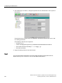
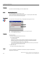
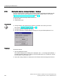
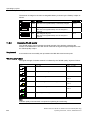
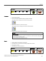
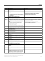
Mobile Panel 277F IWLAN V2, Mobile ___________________
Preface
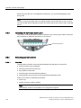
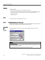
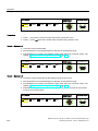
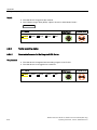
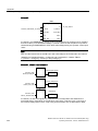
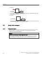
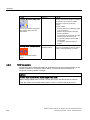
Panel 277F IWLAN
(RFID Tag)
SIMATIC HMI
HMI device
Mobile Panel 277F IWLAN V2,
Mobile Panel 277F IWLAN
(RFID Tag)
Operating Instructions
1
___________________
Overview
Safety instructions and
2
___________________
standards
3
___________________
Planning the use
4
___________________
Installing and wiring devices
Operator controls and
5
___________________
displays
6
___________________
Configuring the HMI device
7
___________________
Safety-related configuration
8
___________________
Commissioning a project
9
___________________
Commissioning the plant
10
___________________
Fail-safe operation
11
___________________
Operating a project
12
___________________
Service and maintenance
13
___________________
Technical specifications
Order number 6AV6691-1DQ01-2AB1
A
___________________
Appendix
B
___________________
Abbreviations
10/2010
A5E02766325-01
Legal information
Legal information
Warning notice system
This manual contains notices you have to observe in order to ensure your personal safety, as well as to prevent
damage to property. The notices referring to your personal safety are highlighted in the manual by a safety alert
symbol, notices referring only to property damage have no safety alert symbol. These notices shown below are
graded according to the degree of danger.
DANGER
indicates that death or severe personal injury will result if proper precautions are not taken.
WARNING
indicates that death or severe personal injury may result if proper precautions are not taken.
CAUTION
with a safety alert symbol, indicates that minor personal injury can result if proper precautions are not taken.
CAUTION
without a safety alert symbol, indicates that property damage can result if proper precautions are not taken.
NOTICE
indicates that an unintended result or situation can occur if the corresponding information is not taken into
account.
If more than one degree of danger is present, the warning notice representing the highest degree of danger will
be used. A notice warning of injury to persons with a safety alert symbol may also include a warning relating to
property damage.
Qualified Personnel
The product/system described in this documentation may be operated only by personnel qualified for the specific
task in accordance with the relevant documentation for the specific task, in particular its warning notices and
safety instructions. Qualified personnel are those who, based on their training and experience, are capable of
identifying risks and avoiding potential hazards when working with these products/systems.
Proper use of Siemens products
Note the following:
WARNING
Siemens products may only be used for the applications described in the catalog and in the relevant technical
documentation. If products and components from other manufacturers are used, these must be recommended
or approved by Siemens. Proper transport, storage, installation, assembly, commissioning, operation and
maintenance are required to ensure that the products operate safely and without any problems. The permissible
ambient conditions must be adhered to. The information in the relevant documentation must be observed.
Trademarks
All names identified by ® are registered trademarks of the Siemens AG. The remaining trademarks in this
publication may be trademarks whose use by third parties for their own purposes could violate the rights of the
owner.
Disclaimer of Liability
We have reviewed the contents of this publication to ensure consistency with the hardware and software
described. Since variance cannot be precluded entirely, we cannot guarantee full consistency. However, the
information in this publication is reviewed regularly and any necessary corrections are included in subsequent
editions.
Siemens AG
Industry Sector
Postfach 48 48
90026 NÜRNBERG
GERMANY
order number: 6AV6 691-1DQ01-2AB1
Ⓟ 10/2010
Copyright © Siemens AG 2010.
Technical data subject to change
Preface
Purpose of the operating instructions
These operating instructions provide information for manuals derived from the requirements
for mechanical engineering documentation according to DIN EN 62079. This information
relates to the place of use, transport, storage, mounting, use and maintenance.
These operating instructions are intended for:
● Users
● Commissioning engineers
● Maintenance personnel
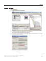
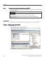
Pay particular attention to the section "Safety instructions and standards (Page 43)".
You can find more information such as operating instructions, examples and reference
information in the online help of WinCC flexible.
Required knowledge
General knowledge of automation technology and process communication is needed to
understand the operating instructions.
It is also assumed that those using the manual have experience in using personal computers
and an understanding of Microsoft operating systems.
Scope of this manual
The manual applies for the HMI devices "Mobile Panel 277F IWLAN V2" and "Mobile Panel
277F IWAN (RFID Tag)" in connection with the following software:
● STEP 7 V5.4, starting with SP2
● Optional package "SIMATIC S7 Distributed Safety V5.4", SP3 or higher
● WinCC flexible 2008, SP2 with HSP "Mobile Panel 277 Wireless V2.0"
NOTICE
Manual belongs to HMI device
The supplied manual belongs to the HMI device and is also required to repeat
commissioning. Keep all supplied and supplementary documentation for the entire
service life of the HMI device.
Provide all stored documents to subsequent owners of the HMI device.
Mobile Panel 277F IWLAN V2, Mobile Panel 277F IWLAN (RFID Tag)
Operating Instructions, 10/2010, A5E02766325-01
3
Preface
Trademarks
The following names marked with the ® symbol are registered trademarks of Siemens AG:
● HMI®
● SIMATIC®
● WinCC®
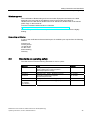
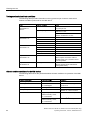
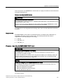
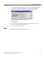
Style conventions
Style Convention
Scope
"Add screen"
Terminology that appears in the user interface, for example
dialog names, tabs, buttons, menu commands
Required input, for example, limits, tag values.
Path information
"File > Edit"
Operational sequences, for example, menu commands, shortcut
menu commands.
<F1>, <Alt+P>
Keyboard operation
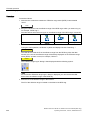
Please observe notes labeled as follows:
Note
A note contains important information about the product described in the manual and its use,
or a specific section of the manual to which you should pay particular attention.
Naming conventions
Term
Applies to
Plant
System
Machining center
One or more machines
Actuate
By means of the touch screen on the HMI device
By operating a mouse on the HMI device
Mobile Panel 277F IWLAN
Mobile Panel 277F IWLAN V2
Mobile Panel 277F IWLAN (RFID Tag)
Mobile Panel 277F IWLAN V1
Previous version of the Mobile Panel 277F IWLAN
Range name
Describes an effective range which is recognized by an HMI
device
Figures
This manual contains illustrations of the described devices. The illustrations can deviate from
the particularities of the delivered device.
4
Mobile Panel 277F IWLAN V2, Mobile Panel 277F IWLAN (RFID Tag)
Operating Instructions, 10/2010, A5E02766325-01
Preface
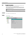
Technical Support
Technical support for the products covered in the manual is available in the Internet at:
● Technical Support (http://support.automation.siemens.com/WW/view/en/4000024)
● Support Request (http://support.automation.siemens.com/WW/view/en/16605654)
● Service (http://support.automation.siemens.com/WW/view/en/16604318)
● Contacts and office locations
(http://www.automation.siemens.com/mcms/aspa-db/en/Pages/default.aspx)
● Training center (http://sitrain.automation.siemens.com/sitrain/default.aspx?AppLang=en)
Additional information on SIMATIC products is available in the Internet at:
● Industry Portal (http://www.automation.siemens.com/_en/portal/index.htm)
● Overall SIMATIC documentation
(http://www.automation.siemens.com/simatic/portal/html_76/techdoku.htm)
Recycling and disposal
The products described in this manual are recyclable because of the low level of
contaminants in their components. Contact a certified disposal service company for
environmentally sound recycling and disposal of your old devices.
Used batteries and rechargeable batteries
Used batteries and lithium ion batteries are hazardous waste. Always dispose of used
batteries and lithium ion batteries properly in accordance with the regulations in effect.
Identify the container provided for this purpose with the label, "Used batteries and
rechargeables".
Note
Batteries and rechargeables do not belong in the garbage. The user is legally obliged to
return used batteries and rechargeable batteries. You can deposit used batteries and
rechargeables at any public collection site and anywhere batteries or rechargeables of
similar type are sold.
You can also send batteries and rechargeables to the following address:
Siemens AG
Industry Sector
Returns Center
Siemensstr. 2
90766 Fürth
Germany
Mobile Panel 277F IWLAN V2, Mobile Panel 277F IWLAN (RFID Tag)
Operating Instructions, 10/2010, A5E02766325-01
5
Preface
6
Mobile Panel 277F IWLAN V2, Mobile Panel 277F IWLAN (RFID Tag)
Operating Instructions, 10/2010, A5E02766325-01
Table of contents
Preface ...................................................................................................................................................... 3
1
2
3
Overview.................................................................................................................................................. 15
1.1
Product overview .........................................................................................................................15
1.2
Scope of delivery .........................................................................................................................15
1.3
Mobile Panel 277F IWLAN...........................................................................................................16
1.4
Accessory kit ................................................................................................................................18
1.5
Accessories..................................................................................................................................18
1.6
1.6.1
1.6.2
1.6.3
1.6.4
1.6.5
Equipment for HMI device and plant............................................................................................19
Charging station ...........................................................................................................................20
Power supply unit.........................................................................................................................21
Transponder.................................................................................................................................22
RFID tag.......................................................................................................................................23
Access point.................................................................................................................................24
1.7
Compatibility of equipment...........................................................................................................25
1.8
Communication and approved controllers ...................................................................................25
1.9
Software requirements.................................................................................................................26
1.10
Supported WinCC flexible objects ...............................................................................................26
1.11
Configuration and process control phases ..................................................................................31
1.12
Ranges in a transponder system .................................................................................................32
1.13
Areas in a RFID tag system .........................................................................................................35
1.14
Rapid Roaming with iPCF and iPCF-MC.....................................................................................37
1.15
Terms for fail-safe operation ........................................................................................................40
Safety instructions and standards............................................................................................................ 43
2.1
Safety instructions........................................................................................................................43
2.2
Approvals .....................................................................................................................................44
2.3
Standards on operating safety .....................................................................................................47
2.4
Operating conditions ....................................................................................................................49
2.5
Risk analysis of the plant .............................................................................................................50
2.6
Safety functions of the EMERGENCY STOP button ...................................................................51
2.7
Safety functions of the enabling mechanism ...............................................................................52
2.8
Electromagnetic compatibility ......................................................................................................54
Planning the use ...................................................................................................................................... 57
3.1
Checklist.......................................................................................................................................57
3.2
Ambient conditions for transportation and storage ......................................................................58
Mobile Panel 277F IWLAN V2, Mobile Panel 277F IWLAN (RFID Tag)
Operating Instructions, 10/2010, A5E02766325-01
7
Table of contents
4
5
3.3
Ambient conditions for operation ................................................................................................ 59
3.4
Insulation resistance, protection class and degree of protection ................................................ 62
3.5
WLAN properties......................................................................................................................... 63
3.6
3.6.1
3.6.1.1
3.6.1.2
3.6.1.3
3.6.2
Equipping a plant with tags ......................................................................................................... 63
Equipping a plant with transponders........................................................................................... 63
Dividing plant into effective ranges ............................................................................................. 63
Dividing plant into zones ............................................................................................................. 66
Quality of the effective range and zone ...................................................................................... 68
Equipping a plant with RFID tags................................................................................................ 69
3.7
Mounting location and clearance of charging station.................................................................. 70
3.8
Planning the installation location of transponders ...................................................................... 71
3.9
Planning an installation location for RFID tags ........................................................................... 72
3.10
Planning the installation location of signal lamps ....................................................................... 73
3.11
Protection zone for the "Override" mode .................................................................................... 73
3.12
Planning protection zones in the RFID tag system..................................................................... 73
3.13
Coexistence of the frequency bands........................................................................................... 75
3.14
Planning information security ...................................................................................................... 77
Installing and wiring devices .................................................................................................................... 81
4.1
Check the scope of delivery ........................................................................................................ 81
4.2
Mounting the charging station ..................................................................................................... 81
4.3
Connecting the charging station ................................................................................................. 82
4.4
Mounting the transponder ........................................................................................................... 83
4.5
Setting the transponder ID and inserting the batteries ............................................................... 83
4.6
Installing an RFID tag.................................................................................................................. 86
4.7
4.7.1
4.7.2
4.7.3
4.7.4
4.7.5
4.7.5.1
4.7.5.2
4.7.5.3
4.7.5.4
4.7.6
4.7.7
4.7.8
4.7.9
4.7.10
Connecting the HMI device ......................................................................................................... 87
Safety instructions....................................................................................................................... 87
Opening and closing the battery and terminal compartment ...................................................... 88
Ports and reset button................................................................................................................. 91
Inserting a memory card ............................................................................................................. 91
Replacing and charging the main rechargeable battery ............................................................. 94
Safety instructions....................................................................................................................... 94
Replacing the main rechargeable battery ................................................................................... 95
Charging the main rechargeable battery..................................................................................... 96
Displaying the battery charge status........................................................................................... 97
Connecting the PLC .................................................................................................................... 97
Connecting the configuration PC ................................................................................................ 98
Connecting a printer.................................................................................................................. 100
Connecting a USB device ......................................................................................................... 101
Connecting the power supply unit............................................................................................. 102
4.8
Switching on and testing the HMI device .................................................................................. 102
4.9
Switching off the HMI device..................................................................................................... 104
Operator controls and displays .............................................................................................................. 105
5.1
8
Overview ................................................................................................................................... 105
Mobile Panel 277F IWLAN V2, Mobile Panel 277F IWLAN (RFID Tag)
Operating Instructions, 10/2010, A5E02766325-01
Table of contents
6
5.2
LED display ................................................................................................................................107
5.3
Power management...................................................................................................................109
5.4
5.4.1
5.4.2
Safety-related operator controls.................................................................................................110
EMERGENCY STOP button ......................................................................................................110
Enabling button ..........................................................................................................................112
5.5
5.5.1
5.5.2
5.5.3
5.5.4
5.5.4.1
5.5.4.2
5.5.4.3
5.5.4.4
5.5.4.5
5.5.4.6
Operator controls .......................................................................................................................115
Operating the handwheel...........................................................................................................115
Operating the key-operated switch ............................................................................................115
Operating the illuminated push-button.......................................................................................116
Evaluating operator controls ......................................................................................................116
Overview ....................................................................................................................................116
Evaluating operator controls as direct keys ...............................................................................117
Controlling the LEDs of the function keys via system functions ................................................120
Controlling the handwheel via system functions........................................................................120
Controlling key-operated switches via system functions ...........................................................121
Controlling and evaluating illuminated mushroom pushbuttons via system functions...............121
5.6
Labeling the function keys .........................................................................................................122
5.7
Holding, operating and setting down the HMI device ................................................................124
5.8
5.8.1
5.8.2
5.8.3
Using the charging station .........................................................................................................126
Charging the main battery in the charging compartment...........................................................126
LED-displays on the charging station ........................................................................................127
Locking the charging station ......................................................................................................128
Configuring the HMI device.................................................................................................................... 129
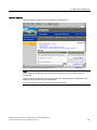
6.1
Desktop and Loader...................................................................................................................129
6.2
Opertaing desktop and loader....................................................................................................132
6.3
Enabling and disabling SecureMode .........................................................................................133
6.4
6.4.1
6.4.2
6.4.3
6.4.4
6.4.5
6.4.5.1
6.4.5.2
6.4.5.3
6.4.5.4
6.4.5.5
6.4.5.6
Control Panel .............................................................................................................................133
Overview ....................................................................................................................................133
Functions in the Control Panel...................................................................................................134
Operating the Control Panel ......................................................................................................136
Using the screen keyboard in the Control Panel .......................................................................136
Configuring operation.................................................................................................................139
Configuring the screen keyboard ...............................................................................................139
Changing display brightness......................................................................................................140
Setting the character repeat rate of the screen keyboard .........................................................141
Setting the double-click..............................................................................................................142
Calibrating the touch screen ......................................................................................................143
Starting the HMI device again....................................................................................................144
6.5
Entering and deleting a password..............................................................................................146
6.6
6.6.1
6.6.2
6.6.3
WLAN communication ...............................................................................................................147
Overview ....................................................................................................................................147
Assigning WLAN communication parameters ...........................................................................151
Assigning iPCF-MC parameters ................................................................................................156
6.7
6.7.1
6.7.2
6.7.3
6.7.4
General settings.........................................................................................................................159
Setting the date and time ...........................................................................................................159
Backing up registry information and temporary data .................................................................161
Displaying information about the HMI device ............................................................................162
Display firmware ........................................................................................................................163
Mobile Panel 277F IWLAN V2, Mobile Panel 277F IWLAN (RFID Tag)
Operating Instructions, 10/2010, A5E02766325-01
9
Table of contents
7
8
10
6.7.5
6.7.6
6.7.7
6.7.8
6.7.9
6.7.10
6.7.11
6.7.12
6.7.13
6.7.14
6.7.15
Display the charging status and temperature of the rechargeable battery ............................... 163
Selecting transponders ............................................................................................................. 164
Activate memory management ................................................................................................. 165
Activating vibration alarm .......................................................................................................... 166
Changing the printer properties ................................................................................................ 167
Regional and language settings................................................................................................ 168
Setting the screen saver ........................................................................................................... 169
Displaying general system properties ....................................................................................... 172
Displaying memory distribution ................................................................................................. 172
Setting the location of the project.............................................................................................. 173
Setting the delay time for the project ........................................................................................ 174
6.8
Enabling PROFINET IO ............................................................................................................ 175
6.9
Setting the PROFIsafe address ................................................................................................ 176
6.10
Programming the data channel................................................................................................. 178
6.11
6.11.1
6.11.2
6.11.3
6.11.4
6.11.5
Configuring network operation .................................................................................................. 179
Overview ................................................................................................................................... 179
Specifying the computer name of the HMI device .................................................................... 181
Specifying the IP address and name server ............................................................................. 182
Specifying the logon data.......................................................................................................... 184
Configuring e-mail ..................................................................................................................... 185
6.12
6.12.1
6.12.2
6.12.3
6.12.4
Changing Internet settings ........................................................................................................ 187
Changing general settings ........................................................................................................ 187
Setting the proxy server ............................................................................................................ 188
Changing privacy settings ......................................................................................................... 189
Importing, displaying and deleting certificates .......................................................................... 190
6.13
Saving to external storage medium – backup ........................................................................... 192
6.14
Restoring from external storage medium – Restore ................................................................. 194
Safety-related configuration ................................................................................................................... 197
7.1
General procedure .................................................................................................................... 197
7.2
Checklist for configuration......................................................................................................... 198
7.3
7.3.1
7.3.2
7.3.3
7.3.4
7.3.5
7.3.6
7.3.7
SIMATIC STEP 7 ...................................................................................................................... 199
Configuring in STEP 7............................................................................................................... 199
Assigning parameters for communication between the HMI device and the controller ............ 200
"SIMATIC S7 Distributed Safety" add-on.................................................................................. 203
Checklist for EMERGENCY STOP configuration...................................................................... 203
Using F-FBs .............................................................................................................................. 205
F_FB_MP................................................................................................................................... 208
F_FB_RNG_4 and F_FB_RNG_16............................................................................................ 212
7.4
Configuration in WinCC flexible ................................................................................................ 216
Commissioning a project........................................................................................................................ 217
8.1
Using an existing project ........................................................................................................... 217
8.2
Operating modes....................................................................................................................... 217
8.3
Available data channels ............................................................................................................ 218
8.4
8.4.1
8.4.2
Preparing and backing up a project .......................................................................................... 219
Overview ................................................................................................................................... 219
Transfer ..................................................................................................................................... 219
Mobile Panel 277F IWLAN V2, Mobile Panel 277F IWLAN (RFID Tag)
Operating Instructions, 10/2010, A5E02766325-01
Table of contents
8.4.2.1
8.4.2.2
8.4.2.3
8.4.3
8.4.4
8.4.4.1
8.4.4.2
8.4.4.3
8.4.4.4
8.4.4.5
8.4.5
8.4.5.1
8.4.5.2
8.4.5.3
8.4.6
8.4.6.1
8.4.6.2
8.4.6.3
8.4.7
8.4.7.1
8.4.7.2
8.4.7.3
8.4.7.4
8.4.7.5
8.4.8
8.4.8.1
8.4.8.2
8.4.8.3
9
10
Overview ....................................................................................................................................219
Starting manual transfer.............................................................................................................221
Starting backtransfer..................................................................................................................221
Testing a project ........................................................................................................................222
Backup and restore....................................................................................................................224
Overview ....................................................................................................................................224
Backing up with WinCC flexible .................................................................................................225
Backing up with ProSave ...........................................................................................................226
Restoring with WinCC flexible....................................................................................................227
Restoring with ProSave .............................................................................................................228
Updating the operating system ..................................................................................................229
Overview ....................................................................................................................................229
Updating the operating system using WinCC flexible................................................................230
Updating the operating system using ProSave..........................................................................231
Restoring factory settings ..........................................................................................................232
Overview ....................................................................................................................................232
Restoring the factory settings using WinCC flexible. .................................................................232
Restoring the factory settings with ProSave ..............................................................................234
Installing and removing software options...................................................................................237
Overview ....................................................................................................................................237
Installing with WinCC flexible.....................................................................................................237
Removing with WinCC flexible...................................................................................................238
Installing with ProSave...............................................................................................................239
Removing with ProSave.............................................................................................................240
Transferring and transferring back license keys ........................................................................240
Overview ....................................................................................................................................240
Transfer license keys .................................................................................................................241
Transfer license keys back ........................................................................................................242
Commissioning the plant ....................................................................................................................... 243
9.1
Overview ....................................................................................................................................243
9.2
Acceptance of the plant .............................................................................................................243
9.3
9.3.1
9.3.2
9.3.3
Transponder system ..................................................................................................................244
Accepting effective range...........................................................................................................244
Test effective range ...................................................................................................................247
Testing zones.............................................................................................................................247
9.4
9.4.1
9.4.2
RFID tag system ........................................................................................................................248
Commissioning an RFID tag ......................................................................................................248
Replacing an RFID tag...............................................................................................................251
9.5
Diagnostics.................................................................................................................................252
Fail-safe operation ................................................................................................................................. 255
10.1
Organizational measures ...........................................................................................................255
10.2
Integrating the HMI device .........................................................................................................256
10.3
10.3.1
10.3.2
10.3.3
10.3.4
10.3.5
Operating the transponder system in a fail-safe mode ..............................................................257
Switch-off behavior ....................................................................................................................257
Determine the current effective range and current zone ...........................................................258
Logging onto a machine.............................................................................................................259
Logging off the machine.............................................................................................................261
Activating and deactivating "Override" mode.............................................................................261
10.4
10.4.1
RFID tag system run in a fail-safe manner ................................................................................264
Switch-off behavior ....................................................................................................................264
Mobile Panel 277F IWLAN V2, Mobile Panel 277F IWLAN (RFID Tag)
Operating Instructions, 10/2010, A5E02766325-01
11
Table of contents
11
10.4.2
10.4.3
Logging onto a machine............................................................................................................ 265
Logging off the machine............................................................................................................ 268
10.5
Removing the HMI device ......................................................................................................... 269
Operating a project ................................................................................................................................ 271
11.1
Starting the project .................................................................................................................... 271
11.2
Operator input options............................................................................................................... 272
11.3
Direct keys................................................................................................................................. 274
11.4
Setting the project language ..................................................................................................... 275
11.5
Operating the screen keyboard in the project ........................................................................... 276
11.6
11.6.1
11.6.2
11.6.3
11.6.4
11.6.5
11.6.6
11.6.7
Device-specific displays ............................................................................................................ 279
Showing the battery charge ...................................................................................................... 279
Displaying WLAN quality........................................................................................................... 280
Display "effective range name" object ...................................................................................... 281
Displaying the "Effective range name (RFID)" object ............................................................... 281
Display "effective range quality" object ..................................................................................... 282
Display "zone name" object ...................................................................................................... 283
Display "zone quality" object ..................................................................................................... 283
11.7
11.7.1
11.7.2
11.7.3
11.7.4
11.7.5
11.7.6
11.7.7
Project security.......................................................................................................................... 284
Overview ................................................................................................................................... 284
User View .................................................................................................................................. 286
User logon ................................................................................................................................. 287
User logoff ................................................................................................................................. 288
Creating users........................................................................................................................... 288
Changing user data................................................................................................................... 290
Deleting users ........................................................................................................................... 291
11.8
Function keys ............................................................................................................................ 291
11.9
Bar............................................................................................................................................. 292
11.10
Gauge........................................................................................................................................ 293
11.11
Operating the slider control ....................................................................................................... 293
11.12
Operating the switch ................................................................................................................. 294
11.13
Operating the Trend View ......................................................................................................... 295
11.14
Operating the status force......................................................................................................... 297
11.15
Operating the Sm@rtClient view............................................................................................... 299
11.16
Operate alarm view and alarm window..................................................................................... 301
11.16.1 Overview ................................................................................................................................... 301
11.16.2 Recognizing pending alarms..................................................................................................... 303
11.16.3 Alarm view................................................................................................................................. 303
11.16.3.1 Overview .............................................................................................................................. 303
11.16.3.2 Displaying alarms................................................................................................................. 304
11.16.3.3 Display alarm window .......................................................................................................... 306
11.16.4 Display infotexts for an alarm.................................................................................................... 306
11.16.5 Acknowledge alarm................................................................................................................... 306
11.16.6 Edit alarm .................................................................................................................................. 307
11.17
Operating recipes...................................................................................................................... 308
11.17.1 Overview ................................................................................................................................... 308
12
Mobile Panel 277F IWLAN V2, Mobile Panel 277F IWLAN (RFID Tag)
Operating Instructions, 10/2010, A5E02766325-01
Table of contents
11.17.2 Structure of a recipe...................................................................................................................308
11.17.3 Recipes in the Project ................................................................................................................310
11.17.4 Recipe displays..........................................................................................................................312
11.17.5 Recipe Values in the HMI Device and the PLC .........................................................................314
11.17.6 Operating the recipe view ..........................................................................................................316
11.17.6.1 Overview ...............................................................................................................................316
11.17.6.2 Creating a recipe data record ...............................................................................................317
11.17.6.3 Editing a recipe data record..................................................................................................319
11.17.6.4 Deleting a recipe data record................................................................................................320
11.17.6.5 Synchronizing tags................................................................................................................320
11.17.6.6 Reading a recipe data record from the PLC .........................................................................321
11.17.6.7 Transferring a recipe data record to the PLC .......................................................................322
11.17.7 Using the simple recipe view .....................................................................................................323
11.17.7.1 Overview ...............................................................................................................................323
11.17.7.2 Creating a recipe data record ...............................................................................................325
11.17.7.3 Editing a recipe data record..................................................................................................325
11.17.7.4 Deleting a recipe data record................................................................................................326
11.17.7.5 Reading a recipe data record from the PLC .........................................................................327
11.17.7.6 Transferring a recipe data record to the PLC .......................................................................327
11.17.8 Exporting a recipe data record...................................................................................................328
11.17.9 Importing a recipe data record ...................................................................................................329
11.17.10 Examples ...................................................................................................................................330
11.17.10.1 Entering a recipe data record ...............................................................................................330
11.17.10.2 Manual production sequence................................................................................................331
11.18
12
13
A
Closing the project .....................................................................................................................331
Service and maintenance ...................................................................................................................... 333
12.1
Maintenance and care ...............................................................................................................333
12.2
Spare parts and repairs .............................................................................................................334
Technical specifications......................................................................................................................... 335
13.1
13.1.1
13.1.2
13.1.3
13.1.4
Dimension drawings...................................................................................................................335
Mobile Panel 277F IWLAN.........................................................................................................335
Charging station .........................................................................................................................337
Transponder...............................................................................................................................338
RFID tag.....................................................................................................................................338
13.2
13.2.1
13.2.2
13.2.3
13.2.4
13.2.5
13.2.6
Specifications .............................................................................................................................340
Mobile Panel 277F IWLAN.........................................................................................................340
Interface description...................................................................................................................343
Main rechargeable battery .........................................................................................................345
Charging station .........................................................................................................................345
Transponder...............................................................................................................................346
RFID tag.....................................................................................................................................346
13.3
13.3.1
13.3.2
WLAN radiation characteristics of the HMI device.....................................................................347
Radiation characteristic in the 2.4 GHz band ............................................................................347
Radiation characteristic in the 5 GHz band ...............................................................................348
13.4
13.4.1
13.4.2
Radiation characteristics of the transponder system .................................................................350
Radiation characteristic of HMI device ......................................................................................350
Radiation characteristic of the transponder ...............................................................................353
Appendix................................................................................................................................................ 357
A.1
ESD guideline ............................................................................................................................357
Mobile Panel 277F IWLAN V2, Mobile Panel 277F IWLAN (RFID Tag)
Operating Instructions, 10/2010, A5E02766325-01
13
Table of contents
B
A.2
A.2.1
A.2.2
A.2.3
A.2.4
A.2.4.1
A.2.4.2
A.2.4.3
A.2.4.4
A.2.4.5
A.2.4.6
A.2.5
A.2.5.1
A.2.5.2
A.2.5.3
A.2.6
A.2.6.1
A.2.6.2
A.2.6.3
A.2.7
A.2.7.1
A.2.7.2
A.2.8
A.2.9
Typical operating procedures and potential fault scenarios...................................................... 359
Overview ................................................................................................................................... 359
Switch on the HMI device.......................................................................................................... 360
Integrating the HMI device ........................................................................................................ 361
Operating the transponder system............................................................................................ 362
Detecting the effective range .................................................................................................... 362
Logging onto a machine............................................................................................................ 363
Exiting the effective range without log off ................................................................................. 364
Logging off the machine............................................................................................................ 366
Activating "override" mode ........................................................................................................ 367
Terminating "override" mode..................................................................................................... 367
Operating RFID tag system....................................................................................................... 369
Logging onto a machine............................................................................................................ 369
Leaving a protection zone without logging off........................................................................... 370
Logging off the machine............................................................................................................ 371
Faulty operating states.............................................................................................................. 372
Communication error for the integrated HMI device ................................................................. 372
Communication errors with logged on HMI device ................................................................... 375
Internal error.............................................................................................................................. 376
Discrepancy error during agreement or panic........................................................................... 377
The enabling button is askew ................................................................................................... 377
The enabling button is defective. .............................................................................................. 378
Removing the HMI device ......................................................................................................... 379
Switching off the HMI device..................................................................................................... 380
A.3
A.3.1
A.3.2
A.3.3
Example of application for transponder system ........................................................................ 382
Configuration and operation...................................................................................................... 382
Configuring the controller and HMI device in STEP 7 .............................................................. 384
Safety program S7 Distributed Safety....................................................................................... 389
A.4
A.4.1
A.4.2
A.4.3
Application example RFID tag system ...................................................................................... 393
Configuration and operation...................................................................................................... 393
Configuring the controller and HMI device in STEP 7 .............................................................. 396
Safety program S7 Distributed Safety....................................................................................... 400
A.5
A.5.1
A.5.2
Safety-related messages .......................................................................................................... 404
Transponder system ................................................................................................................. 404
RFID tag system ....................................................................................................................... 408
A.6
System alarms .......................................................................................................................... 412
A.7
Error cases in the project operation .......................................................................................... 446
Abbreviations......................................................................................................................................... 447
Glossary ................................................................................................................................................ 449
Index...................................................................................................................................................... 457
14
Mobile Panel 277F IWLAN V2, Mobile Panel 277F IWLAN (RFID Tag)
Operating Instructions, 10/2010, A5E02766325-01
1
Overview
1.1
Product overview
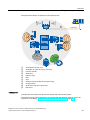
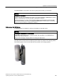
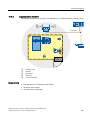
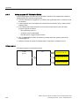
Expanded possible fields of application – with Mobile Panel 277F IWLAN
The Mobile Panel 277F IWLAN is used as a HMI device in fail-safe automation systems. A
fail-safe automation system is required in systems with increased safety requirements.
With the Mobile Panel 277F IWLAN, the system can be operated in the fail-safe mode with
EMERGENCY-STOP button and enabling button without disrupting lines. The HMI device
communicates with an F-CPU via WLAN.
Equipment variants of the Mobile Panel 277F IWLAN are available for operation with
transponder and RFID tag systems. With Mobile Panel 277F IWLAN (RFID Tag), the logging
on to the machine occurs through an RFID-Tag. Once it has been logged on, the
Mobile Panel 277F IWLAN can be used for safe operation of a system.
The outstanding characteristics of the Mobile Panel 277F IWLAN are short commissioning
times, large user memory, high performance, and optimized functionality for projects based
on WinCC flexible and WinCC flexible V11.
The Mobile Panel 277F IWLAN has the following features:
● Safety-related operator controls
– EMERGENCY STOP button
– Enabling button
● Wireless operation with:
– IWLAN interface via PROFINET
– Battery operation
● High-Color-7,5"-TFT-Display
● 18 function keys with LED
● Extended HMI functions
1.2
Scope of delivery
The scope of delivery includes:
● 1 Mobile Panel 277F IWLAN
● 1 main rechargeable battery
● 1 accessory kit
● 1 data carrier with failsafe blocks for safety-related projects, including documents
Additional documents may be included in the scope of delivery.
Mobile Panel 277F IWLAN V2, Mobile Panel 277F IWLAN (RFID Tag)
Operating Instructions, 10/2010, A5E02766325-01
15
Overview
1.3 Mobile Panel 277F IWLAN
1.3
Mobile Panel 277F IWLAN
The Mobile Panel 277F IWLAN works wireless in battery mode or plugged into a charging
station.
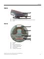
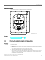
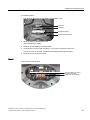
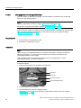
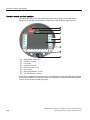
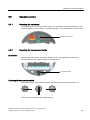
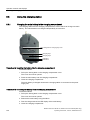
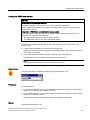
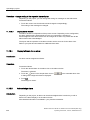
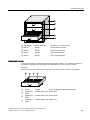
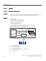
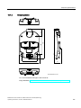
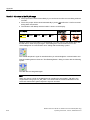
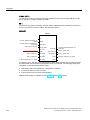
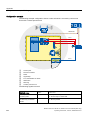
Front view
The following figure shows a fully equipped Mobile Panel 277F IWLAN.
①
②
③
④
⑤
⑥
⑦
⑧
⑨
16
Handwheel, optional
EMERGENCY STOP button
LED display
Membrane keyboard
Display with touch screen
Key "ON/OFF"
Covers for the labeling strips for the slot openings
Illuminated pushbutton, optional
Key-operated switch, optional
Mobile Panel 277F IWLAN V2, Mobile Panel 277F IWLAN (RFID Tag)
Operating Instructions, 10/2010, A5E02766325-01
Overview
1.3 Mobile Panel 277F IWLAN
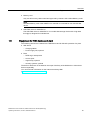
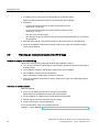
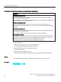
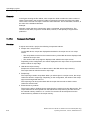
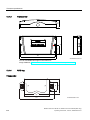
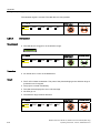
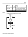
Side view
①
②
③
Fall protection for the EMERGENCY STOP button
Enabling buttons, positioned on both sides of the Mobile Panel 277F IWLAN
Handle
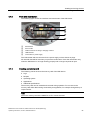
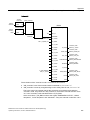
Rear view
①
②
③
④
⑤
⑥
⑦
Nameplate
Handle
Battery compartment cover
Connection compartment cover
Contacts for charging station
USB connection
Connection for power supply
Mobile Panel 277F IWLAN V2, Mobile Panel 277F IWLAN (RFID Tag)
Operating Instructions, 10/2010, A5E02766325-01
17
Overview
1.4 Accessory kit
1.4
Accessory kit
The accessory kit contains:
● 1 cover cap with rubber seal
● 1 screw for fixing the cover cap
● 1 label for cover caps
Additional documents may be enclosed with the accessory kit.
1.5
Accessories
The accessory can be ordered from the Internet at Industry Mall
(http://mall.automation.siemens.com).
● Labeling strips
Labeling strips serve for the project-oriented labeling of function keys on the HMI device.
Stickers for the cover caps can also be supplied, in addition to the labeling strips. The
cover caps cover the slot openings for the labeling strips.
Order number: 6AV6671-5BF00-0AX0
● Replacement key set
The replacement key set contains two keys for the key switch.
Order number: 6AV6574-1AG04-4AA0
● Main battery
The main rechargeable battery supplies power to the HMI device.
Order number: 6AV6671-5CL00-0AX0
● Protective foil
The protective foil prevents the touch screen from becoming scratched or soiled.
Order number: 6AV6671-5BC00-0AX0
● Service package for the HMI device
Order number: 6AV6671-5CA00-0AX2
The service pack includes:
– Cover caps
– Battery compartment cover
18
Mobile Panel 277F IWLAN V2, Mobile Panel 277F IWLAN (RFID Tag)
Operating Instructions, 10/2010, A5E02766325-01
Overview
1.6 Equipment for HMI device and plant
● Memory card
Only use SD memory cards tested and approved by Siemens AG or MicroMemory cards.
Note
The MicroMemory card of the SIMATIC S7 controller is not suited for use with this HMI
device.
● USB Flash drive for SIMATIC PC
The USB Flash drive for SIMATIC PC is a mobile data storage device with a high data
throughput, designed for industrial use.
1.6
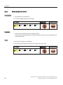
Equipment for HMI device and plant
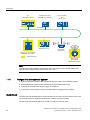
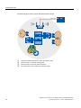
The following devices are needed for the HMI device and for fail-safe operation of a plant:
● HMI device
– Charging station
– Power supply unit, optional
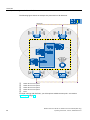
● Plant
– RFID-tag or transponder
– Access point
– Signal lamp, optional
– Security systems, optional
The devices listed are not included in the scope of delivery of the HMI device. Order these
devices separately.
You can find order information on the Internet at Industry Mall
(http://mall.automation.siemens.com).
Mobile Panel 277F IWLAN V2, Mobile Panel 277F IWLAN (RFID Tag)
Operating Instructions, 10/2010, A5E02766325-01
19
Overview
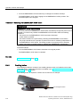
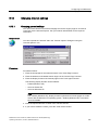
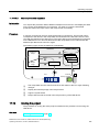
1.6 Equipment for HMI device and plant
1.6.1
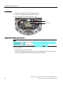
Charging station
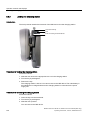
The charging station is used to charge the main battery in the HMI device and to safely store
the HMI device. The charging station is designed to be used in the system.
Order number: 6AV6671-5CE00-0AX1
①
②
③
④
⑤
Lock
Hook for hooking in the HMI device
Charging compartment for one main battery
Charging contact for the HMI device
LED display
On the underside of the charging station you will find the slot for power supply.
Charging station accessory kit
The accessory kit contains:
● 1 lock
● 1 key set for lock
● 1 cable connector
● 4 spacer sleeves for mounting on conductive surfaces
The accessory kit can include documents.
20
Mobile Panel 277F IWLAN V2, Mobile Panel 277F IWLAN (RFID Tag)
Operating Instructions, 10/2010, A5E02766325-01
Overview
1.6 Equipment for HMI device and plant
1.6.2
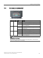
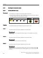
Power supply unit
The power supply unit supplies the power to the HMI device. The power supply unit can be
used in 120 and 230 V AC power networks. The setting of the voltage range takes place
automatically. Output voltage is 12V DC.
①
②
③
④
"Power" LED
Connecting cable
Power supply unit
Power supply cable
Order number: 6AV6671-5CN00-0AX1
The power supply unit is provided with four power supply cables with plugs for the following
regions:
● Europe
● Asia
● North America
● United Kingdom of Great Britain and Northern Ireland
Read the relevant documentation.
Mobile Panel 277F IWLAN V2, Mobile Panel 277F IWLAN (RFID Tag)
Operating Instructions, 10/2010, A5E02766325-01
21
Overview
1.6 Equipment for HMI device and plant
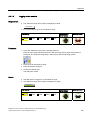
1.6.3
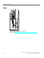
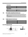
Transponder
A transponder is required for setting up effective ranges in plants with fail safe operation and
for configured zones. The Mobile Panel 277F IWLAN V2 supports the effective range and
zone system.
/DEHOILHOG
Order number: 6AV6671-5CM00-0AX1
Accessory kit
The accessory kit contains:
● 3 AA mignon batteries, 1.5 V
The accessory kit can include documents.
22
Mobile Panel 277F IWLAN V2, Mobile Panel 277F IWLAN (RFID Tag)
Operating Instructions, 10/2010, A5E02766325-01
Overview
1.6 Equipment for HMI device and plant
1.6.4
RFID tag
You need the RFID tag to log on to a machine with the Mobile Panel 277F IWLAN (RFID
tag). The RFID tag is a MDS D100 mobile data storage unit.
Order number: 6GT2600-0AD10
The RFID tag includes the following accessories:
● Spacer
Order number: 6GT2190-0AA00
● Fixing pocket
Order number: 6GT2190-0AB00
$EVWDQGVKDOWHU
%HIHVWLJXQJVWDVFKH
Alternative to the mobile data medium MDS D100, you can also use the mobile data medium
MDS D124 with the order number 6GT2600-0AC00.
The distance between the MDS D124 and the HMI device during logon to the effective range
is max. 2 cm. This is why the MDS D100 should be given preference. This device supports a
maximum distance of 5 cm.
Mobile Panel 277F IWLAN V2, Mobile Panel 277F IWLAN (RFID Tag)
Operating Instructions, 10/2010, A5E02766325-01
23
Overview
1.6 Equipment for HMI device and plant
1.6.5
Access point
The access point is needed for the WLAN. The access point serves as a gateway between
the wireless and wired network.
To use the function iPCF-MC for Rapid Roaming, you need an access point with two
wireless interfaces of the type SCALANCE W78x-2RR and firmware V4.3.
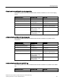
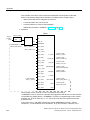
The HMI device supports operation with the following access points:
Designation
Number of
WLAN
interfaces
Antenna
iPCF-MC
Rapid roaming
Order number
SCALANCE
W784-1
1
External
No
6GK5 784-1AA30-2AA0
6GK5 784-1AA30-2AB0 1
SCALANCE
W786-1PRO
1
Internal
No
6GK5 786-1BA60-2AA0
6GK5 786-1BA60-2AB0 1
SCALANCE
W786-2RR
2
Internal
Yes
6GK5 786-2BA60-6AA0
6GK5 786-2BA60-6AB0 1
SCALANCE
W788-1PRO
1
External
No
6GK5 788-1AA60-2AA0
6GK5 788-1AA60-2AB0 1
SCALANCE
W788-2RR
2
External
Yes
6GK5 788-2AA60-6AA0
6GK5 788-2AA60-6AB0 1
SCALANCE
W786-1PRO
1
Internal
No
6GK5 786-1BA60-2AA0
6GK5 786-1BA60-2AB0 1
SCALANCE
W786-2RR
2
Internal
Yes
6GK5 786-2BA60-6AA0
6GK5 786-2BA60-6AB0 1
SCALANCE
W786-2RR
2
External
Yes
6GK5 786-2AA60-6AA0
6GK5 786-2AA60-6AB0 1
1
US version
Read the relevant documentation.
Additional access points and WLAN products are available in the Internet at Industry Mall
(http://mall.automation.siemens.com).
24
Mobile Panel 277F IWLAN V2, Mobile Panel 277F IWLAN (RFID Tag)
Operating Instructions, 10/2010, A5E02766325-01
Overview
1.7 Compatibility of equipment
1.7
Compatibility of equipment
The following devices are compatible with all versions of the Mobile Panel 227F IWLAN:
● Charging station
● Main battery
● Power supply unit
The following applies for the transponder:
● Transponder for the Mobile Panel 277F IWLAN V2
These cannot be used for a Mobile Panel 277F IWLAN V1.
● Transponder for the Mobile Panel 277F IWLAN V1
These can be used without restrictions, but do not support compatibility in the 2.4 GHz
WLAN bandwidth.
1.8
Communication and approved controllers
Number of communication connections
Communication link
Quantity, max.
Mobile Panel 277F IWLAN
6
Approved PLCs
The HMI device has been enabled for use with the following type of PLC:
● SIMATIC S7
● Allen-Bradley, E/IP C.Logix
NOTICE
Safety-related communication
A non-fail-safe controller cannot ensure safety-related communication.
A SIMATIC S7F PLC is required for safety-related communication.
Approved protocols
The HMI device uses the following protocol for communication with the PLC:
● PROFINET
● PROFIsafe Mode V2.0
Mobile Panel 277F IWLAN V2, Mobile Panel 277F IWLAN (RFID Tag)
Operating Instructions, 10/2010, A5E02766325-01
25
Overview
1.9 Software requirements
1.9
Software requirements
You need the following software to configure the HMI device:
● WinCC flexible 2008, SP2 with HSP "Mobile Panel 277 Wireless V2"
● SIMATIC STEP 7 V5.4, as of SP2
● Optional package "SIMATIC S7 Distributed Safety V5.4", SP3 or higher
Software options for the HMI device:
● WinCC flexible/Sm@rtService
The Sm@rtService software option enables remote access via Ethernet to an HMI device
from the HMI device or PC. Read-only access on the removed HMI device is possible.
● WinCC flexible/Sm@rtAccess
The Sm@rtAccess software option allows you to set up communication between different
HMI systems.
● WinCC flexible /Audit
The /Audit software option enhances the functionality of the HMI device with operator
input logging in an audit trail and electronic signature.
● ProAgent
The WinCC flexible /ProAgent option extends the functionality of the HMI device with
specific and high-speed diagnostics of process errors.
1.10
Supported WinCC flexible objects
The following tables contain the maximum number of objects you can use with the HMI
device in a project.
Note
The maximum number of multiple objects used simultaneously can affect the performance of
the active WinCC flexible project.
26
Mobile Panel 277F IWLAN V2, Mobile Panel 277F IWLAN (RFID Tag)
Operating Instructions, 10/2010, A5E02766325-01
Overview
1.10 Supported WinCC flexible objects
Alarms
Object
Specification
Alarm
Number of discrete alarms
4 000
Number of analog alarms
200
Length of the alarm text
Maximum number of tags in an alarm
LEDs
Acknowledge error alarms individually
Acknowledge several error alarms
simultaneously (group acknowledgment of
alarm groups)
Edit alarm
HMI device
80 characters
8
Alarm line, Alarm window,
Alarm view
Yes
16 alarm groups
Yes
Alarm indicator
Yes
ALARM_S
Display S7 alarms
Yes
Alarm buffer, retentive
Alarm buffer capacity
512 alarms
Maximum number of active alarm events
250
View alarm
Yes
Delete alarm buffer
Yes
Line-by-line printing of alarms
Yes
Tags, values and lists
Object
Specification
Tag
Number
HMI device
2048
Limit value monitoring
Input/Output
Yes
Linear scaling
Input/Output
Yes
Text list
Number
500 1
Graphics list
Number
400 1
1
The maximum total of text and graphics lists is 500.
Screens
Object
Specification
Screen
Number
500
Fields per screen
200
Tags per screen
200
Complex objects per screen (for example
bars)
10
Template
Mobile Panel 277F IWLAN V2, Mobile Panel 277F IWLAN (RFID Tag)
Operating Instructions, 10/2010, A5E02766325-01
HMI device
Yes
27
Overview
1.10 Supported WinCC flexible objects
Recipes
Object
Specification
HMI device
Recipe
Number
300
Data records per recipe
500
Entries per recipe
1000
Recipe memory
64 KB
Storage location1)
1
Memory card
USB stick
Network drive
The number of recipe data records might be restricted by the capacity of the storage
medium.
Logs
NOTICE
Logging
The HMI device is suitable for logging small volumes of data. The use of a large circular log
has a negative effect on performance.
In order to log larger amounts of data, use segmented circular logs with multiple sequential
logs.
Object
Specification
HMI device
Logs
Number of logs
20
Number of partial logs in a segmented
circular log
400
Entries in each log including all partial logs
Filing format
Storage location1)
1
28
10000
RDB
CSV with ANSI character
set
TXT (Unicode)
Memory card
USB stick
Network drive
The number of entries in the log may be restricted by the capacity of the storage
medium.
Mobile Panel 277F IWLAN V2, Mobile Panel 277F IWLAN (RFID Tag)
Operating Instructions, 10/2010, A5E02766325-01
Overview
1.10 Supported WinCC flexible objects
Safety
Object
Specification
HMI device
User administration
Number of user groups
50
Number of users
50
Number of authorizations
32
Infotexts
Object
Specification
Infotext
Length (no. of characters)
HMI device
320
(depending on font)
For alarms
Yes
For screens
Yes
For screen objects (for example for I/O
field, switch, button, invisible button)
Yes
Additional functions
Object
Specification
Monitor setting
Touch screen calibration
Yes
Brightness setting
Yes
Number of languages
16
Language change
VBScript
User-specific extension of the functionality
Number of scripts
Graphic object
HMI device
Yes
50
Vector and pixel graphics
Yes
Trend
Number
300
Task planner
Number of tasks
48
Text object
Number
Direct key
PROFINET IO direct keys
Mobile Panel 277F IWLAN V2, Mobile Panel 277F IWLAN (RFID Tag)
Operating Instructions, 10/2010, A5E02766325-01
10000
Yes
29
Overview
1.10 Supported WinCC flexible objects
Device-specific functions
Object
Specification
HMI device
Main battery
Displaying the battery charge status
Yes
WLAN quality
Displaying WLAN quality
Yes
Effective range (RFID) name Display effective range name
Yes
Effective range name 2
Display effective range name
Yes
1
Effective range quality
Zone name 2
Zone quality
2
2
Displaying the effective range quality
Yes
Displaying zone names
Yes
Displaying zone quality
Yes
1
Applies for Mobile Panel 277F IWLAN (RFID Tag)
2
Applies for Mobile Panel 277F IWLAN
Functions for transponder system
Configuration
Number of transponders available for all effective ranges in the project
127
Number of effective ranges in the project, maximum
127
Number of transponders in the effective range, maximum
127
Number of HMI devices with logon authorization per effective range,
when using F_FB_RNG_4, maximum
4 HMI devices
Number of HMI devices with logon authorization per effective range,
when using F_FB_RNG_16, maximum
16 HMI devices
Functions for RFID tag system
Configuration
30
Number of RFID tags in the project, maximum
127
Number of effective ranges in the project, maximum
127
Number of RFID tags per effective range, maximum
127
Maximum number of HMI devices with logon authorization per effective
range when using F_FB_RNG_4
4 HMI devices
Maximum number of HMI devices with logon authorization per effective
range when using F_FB_RNG_16
16 HMI devices
Mobile Panel 277F IWLAN V2, Mobile Panel 277F IWLAN (RFID Tag)
Operating Instructions, 10/2010, A5E02766325-01
Overview
1.11 Configuration and process control phases
1.11
Configuration and process control phases
You must follow the phases below in order to use an HMI device in the system:
● Configuration phase
● Process control phase
Configuration phase
The configuration phase consists of the following operations:
● Create project
● Transferring a project
6DIHW\UHODWHGSURMHFW
&RQILJXULQJ3&
0RELOH3DQHO),:/$1
● Accept project – determine checksum
● Test project
● Simulate project
● Save project
Process control phase
The process control phase includes operation and monitoring of active production processes
with the HMI device. The HMI screens on the HMI device visualize the production process.
The following figure shows an example configuration of a plant control system which is
operated with a Mobile Panel 277F IWLAN.
Mobile Panel 277F IWLAN V2, Mobile Panel 277F IWLAN (RFID Tag)
Operating Instructions, 10/2010, A5E02766325-01
31
Overview
1.12 Ranges in a transponder system
,2
352),1(7,2GHYLFH
6WDQGDUG+RVW3/&
352),1(7,2FRQWUROOHU
(7b6VWDWLRQ
ZLWK
,031
352),1(7
6,0$7,&6)
6&$/$1&(
$FFHVV3RLQW
6,0$7,&6)31'3
352),1(7,2FRQWUROOHU
)DLOVDIHGHYLFHV
0RELOH3DQHO
),:/$1
352),1(7,2'HYLFH
Note
Simultaneous safety-related communication with two F-CPUs is not possible. PROFIsafe
supports safety-related communication with one F-CPU.
1.12
Ranges in a transponder system
In a plant for fail-safe operation with transponder log ons, there are the following ranges:
● WLAN/IWLAN for communication between an F-CPU and an HMI device
● Transponder with effective range for logon to a machine
● Transmission and reception range of an HMI device for logging onto a machine
WLAN/IWLAN
Fail-safe controller and HMI device communicate over the radio cell of the access point. The
access point serves as a gateway between the wireless and wired network.
The WLAN or IWLAN in the plant is provided by at least one access point.
32
Mobile Panel 277F IWLAN V2, Mobile Panel 277F IWLAN (RFID Tag)
Operating Instructions, 10/2010, A5E02766325-01
Overview
1.12 Ranges in a transponder system
The figure below shows an example of the various areas.
352),VDIH
①
②
③
④
⑤
⑥
⑦
⑧
⑨
⑩
⑪
SCALANCE W access point
WLAN/IWLAN, radio cell of the access point
Fail-safe controller
Signal lamp
Effective range
Plant
Zone
Wireless range of the HMI device (green range)
Charging station
WLAN of the HMI device (blue lines)
HMI device
Transponder
Transponders are used to set up effective ranges and zones in the system.
The wireless range of the transponder corresponds with the effective range or zone in its
expansion. See chapter "Radiation characteristic of the transponder (Page 353)".
Mobile Panel 277F IWLAN V2, Mobile Panel 277F IWLAN (RFID Tag)
Operating Instructions, 10/2010, A5E02766325-01
33
Overview
1.12 Ranges in a transponder system
Effective range
An effective range is the range in which sections of the system, e.g. a machine, can be
operated in failsafe mode using enabling buttons. Operating with the enabling button is not
possible outside of the effective range.
Fail-safe operation is only possible after successfully logging on to a machine. A signal lamp
indicates whether an HMI device is logged onto a machine.
The effective range is a configurable object. The size of the effective range is defined in the
project.
Zone
A zone is used to operate and observe depending on the location of the operator. For
example, a screen change can be configured for entering or exiting a zone. The enabling
buttons are not effective.
Fail-safe operation is not possible in a zone.
The zone is a configurable object within a transponder system.
Note
The zone and effective range are independent of each other. For fail-safe operation, at least
one effective range must be configured. A zone cannot be configured for fail-safe operation.
Transponder system in the "override" mode
In the "override" mode, the effective range monitoring is disabled and fail-safe operation is
possible throughout the entire WLAN range. The components that are operated fail-safe
must be separated through a safety system, for example, a protective gate.
The "override" mode is used in the following cases:
● Components should undergo fail-safe operation if they cannot be reached from the
wireless range of one or multiple transponders.
● A component should be operated fail-safe for which there is already a safety system.
34
Mobile Panel 277F IWLAN V2, Mobile Panel 277F IWLAN (RFID Tag)
Operating Instructions, 10/2010, A5E02766325-01
Overview
1.13 Areas in a RFID tag system
Protection zone
The protection zone is the area in the plant in which one or more machines are operated in
fail-safe mode.
The protection zone is not an object that can be configured.
The protection zone of the system must be demarcated by a safety system and
organizational measures. The following measures have to be taken for safe operation of the
transponder system in "Override" mode:
● Safety system
The safety system consists of one or more technical protection devices for the protection
zone, e.g.:
– Mesh fence with access
– Light barrier
– Safety contact mat, optional
● Organizational safety measures
The safety system must be supplemented with a system control program that controls
access to the protection zone.
1.13
Areas in a RFID tag system
The following areas are available in a plant for fail-safe operation with RFID tag logon:
● WLAN/IWLAN for communication between an F-CPU and an HMI device
● RFID tag with effective range for logon to a machine
● RFID transmission and reception range of an HMI device
WLAN/IWLAN
F-CPU and HMI device communicate via the radio cell of the access point. The access point
serves as a gateway between the wireless and wired network.
At least one access point is provided for WLAN or IWLAN in the plant.
Mobile Panel 277F IWLAN V2, Mobile Panel 277F IWLAN (RFID Tag)
Operating Instructions, 10/2010, A5E02766325-01
35
Overview
1.13 Areas in a RFID tag system
The figure below shows an example of the various areas.
352),VDIH
①
②
③
④
⑤
⑥
⑦
⑧
⑨
⑩
⑪
⑫
SCALANCE W access point
WLAN/IWLAN, radio cell of the access point
Fail-safe controller
Signal lamp
RFID tag with effective range
Plant
Protection zone limit of protection zone 1
Protection zone limit of protection zone 2
WLAN of the HMI device
Charging station
RFID transmission and reception range of the HMI device
HMI device
RFID tag with effective range
The RFID tag is a storage device for a configured ID. The ID of the RFID tag is required for a
HMI device to log onto a machine. To log on the HMI device, its RFID transmission and
reception range must be within the effective range of the RFID tag.
A signal lamp indicates whether an HMI device is logged onto a machine.
36
Mobile Panel 277F IWLAN V2, Mobile Panel 277F IWLAN (RFID Tag)
Operating Instructions, 10/2010, A5E02766325-01
Overview
1.14 Rapid Roaming with iPCF and iPCF-MC
Protection zone
The protection zone is the area in the plant in which one or more machines are operated in
fail-safe mode.
The protection zone is not a configurable object.
The protection zone of the system must be demarcated by a safety system and
organizational measures. The following measures have to be taken for safe operation of an
RFID tag system:
● Safety system
The safety system consists of one or more technical protection devices for the protection
zone, e.g.:
– Mesh fence with access
– Light barrier
– Contact safety shut-off mat
● Organizational safety measures
The safety system must be supplemented with a system control program that controls
access to the protection zone.
1.14
Rapid Roaming with iPCF and iPCF-MC
The wireless range of an IWLAN system can be extended using several access points. The
wireless connection of an HMI device that is moved between SCALANCE W78x access
point ranges is briefly interrupted and then recovered (roaming).
Capabilities provided by iPCF
In the industrial environment, there are applications that require deterministic behavior for a
large number of participants and high data throughput in a cell. Moreover, a deterministic
behavior is required for cell cross-overs with handover times of less than 100 ms.
The iPCF extension (Industrial Point Coordination Function) was developed to meet these
requirements.
iPCF ensures that all data traffic runs in coordinated fashion in a wireless cell, controlled by
the access point. It also optimizes the throughput with a high number of participants by
avoiding collisions. iPCF also facilitates very fast cell changes.
Special features provided by iPCF-MC
iPCF-MC was designed to enable free-moving participants to exploit the special advantages
provided by iPCF, which allows communication independent of an RCoax line or directional
antennas. With iPCF-MC, the client looks for potentially suitable access points even when it
is receiving iPCF queries from the access point and the existing connection to an access
point is functioning correctly. This makes it possible to switch to another access point very
quickly if it becomes necessary. Unlike iPCF, with iPCF-MC the handover times do not
depend on the number of radio channels in use.
Mobile Panel 277F IWLAN V2, Mobile Panel 277F IWLAN (RFID Tag)
Operating Instructions, 10/2010, A5E02766325-01
37
Overview
1.14 Rapid Roaming with iPCF and iPCF-MC
The following figure shows an example of a plant with four WLAN areas.
352),VDIH
①
②
③
④
⑤
Radio cell of access point 1
Radio cell of access point 2
Radio cell of access point 3
Radio cell of access point 4
Plant
For rapid roaming with iPCF-MC, you will require a suitable access point – see section
"Access point (Page 24)".
38
Mobile Panel 277F IWLAN V2, Mobile Panel 277F IWLAN (RFID Tag)
Operating Instructions, 10/2010, A5E02766325-01
Overview
1.14 Rapid Roaming with iPCF and iPCF-MC
Stable PNIO communication requires that a WLAN client is available at all times in a radio
cell with a signal strength > 60% or > -65 dBm. This can be checked by switching the various
segments on and off.
This does not mean that the client needs to change over at a signal strength < 60% or < -65
dBm. Make sure that you provide access points with sufficient signal strength.
Limitations due to iPCF-MC
iPCF-MC is an in-house development of the Siemens AG that will only work with participants
in which iPCF-MC has been installed.
Operating principle of iPCF-MC
iPCF-MC uses both radio interfaces of the access point differently: One interface works as
management interface and sends a beacon every five milliseconds. The other interface
transmits the user data.
The following requirements have to be met to use iPCF-MC:
● All "RR" versions of the SCALANCE W-700 access points with at least two WLAN
interfaces can be used as access point. The HMI device and all SCALANCE W-700 "RR"
versions are suitable for operation in client mode.
● You have to operate the management interface and the data interface in the same
frequency range; they also have to match in their radio coverage. iPCF-MC will not work if
both radio interfaces are equipped with directional antenna the cover different areas.
● The management interfaces of all access points that a client is to access must use the
same channel. A client will only scan this one channel to find all available access points.
● You cannot use the transmission method to IEEE 802.11h for the management interface.
802.11h can be used for the data interface.
Mobile Panel 277F IWLAN V2, Mobile Panel 277F IWLAN (RFID Tag)
Operating Instructions, 10/2010, A5E02766325-01
39
Overview
1.15 Terms for fail-safe operation
1.15
Terms for fail-safe operation
Fail-safe automation system
A fail-safe automation system is required in a plant with high safety requirements.
In an EMERGENCY STOP, the fail-safe automation system brings the plant to a safe
operating state regardless of the situation. Shutdown of the plant therefore does not pose a
danger to people or the plant.
Fail-safe operation
The HMI device registers signals from the EMERGENCY STOP button and the enabling
button during fail-safe operation. The controller and the HMI device communicate with each
other via PROFIsafe.
Configuration of the safety functions in STEP 7 with the "SIMATIC S7 Distributed Safety"
add-on package can achieve fail-safe operation according to SIL 3 or Performance Level e
and Category 4 for the HMI device.
Integration and removal
● Integrating
Integration means to establish safety-related communication between the HMI device and
the fail-safe controller via PROFIsafe.
The EMERGENCY STOP button is enabled in integrated operating mode.
● Removing
Removal means to intentionally stop safety-related communication between the HMI
device and the fail-safe controller via PROFIsafe.
Logging on the HMI device
The HMI device must be logged onto a machine in order to operate the machine after
integration in fail-safe operation with the enabling button. Logging on to the machine occurs
through a transponder or through an RFID tag.
Logging off an HMI device
Logging off an HMI device from a machine terminates fail-safe operation with the enabling
button.
● Forced logoff
If the safety system is triggered, for example by the operator leaving the protection zone
without logging off, a forced logoff is performed by the machine. The HMI device revokes
the operator authorization for the enabling button. The operator is prompted to confirm
the "Forced logoff" dialog.
● Automatic logoff in the event of a communication error
If a communication error occurs, the HMI device is removed from the safety-related
communication. The HMI device is logged off from the machine by means of a safety
program. The fail-safe controller brings the plant to a safe operating state.
40
Mobile Panel 277F IWLAN V2, Mobile Panel 277F IWLAN (RFID Tag)
Operating Instructions, 10/2010, A5E02766325-01
Overview
1.15 Terms for fail-safe operation
Shutdown response of the plant
● The following shutdown response of the plant applies regardless of whether or not the
HMI device is logged onto a machine.
– EMERGENCY STOP
EMERGENCY STOP is an action that is intended to stop a process or motion
associated with danger in accordance with EN 60204-1, appendix E. An
EMERGENCY STOP immediately stops all parts of the plant controlled by the fail-safe
controller via a safety program. The EMERGENCY STOP button is always enabled
when there is PROFIsafe communication between HMI device and fail-safe controller,
i.e. when the HMI device is integrated in the PROFIsafe communication.
– Global rampdown
A global rampdown is a procedure for reaching a safe operating state of the system.
You have to define and program the reaction to PROFIsafe communication. The
machine manufacturer has to specify the procedure for setting the system to a safe
operating state. EN 60204-1 defines possible stop categories. See chapter "Safety
functions of the EMERGENCY STOP button (Page 51)".
The global rampdown is independent of the area.
The global rampdown is triggered by the fail-safe controller, for example, if an error
occurs with an HMI device integrated in the PROFIsafe communication.
● The following shutdown response of the plant applies when the HMI device is logged onto
a machine.
– Local rampdown
A global rampdown is a procedure for reaching a safe operating state of the plant unit.
You have to define and program the reaction to PROFIsafe communication. The
machine manufacturer has to specify the procedure for setting the system to a safe
operating state. EN 60204-1 defines possible stop categories.
The local rampdown is triggered, for example, when the operator leaves the protection
zone without logging off via a safety system.
– Shutdown
The shutdown is triggered as soon as the F-CPU detects a communication error at an
HMI device that is logged on to a machine. Shutdown is the immediate stop of all
machinery being operated in fail-safe mode.
Communication error
A communication error occurs when the communication between HMI device and fail-safe
controller is interrupted. Additional information is available in the section "Faulty operating
states (Page 372)".
Mobile Panel 277F IWLAN V2, Mobile Panel 277F IWLAN (RFID Tag)
Operating Instructions, 10/2010, A5E02766325-01
41
Overview
1.15 Terms for fail-safe operation
42
Mobile Panel 277F IWLAN V2, Mobile Panel 277F IWLAN (RFID Tag)
Operating Instructions, 10/2010, A5E02766325-01
Safety instructions and standards
2.1
2
Safety instructions
WARNING
Injury or material damage
If you do not exactly adhere to the safety regulations and procedural instructions contained
in this manual, hazards may arise and safety features be rendered ineffective. This can
result in personal injuries or material damage.
Closely follow closely the safety regulations and procedural instructions in each situation.
Observe the regulations for safety and accident prevention applicable to your application in
addition to the safety instructions given in this manual.
Project security
WARNING
Injury or material damage
The configuration engineer for plant control must take precautions to ensure that an
interrupted program will be correctly integrated again after communication failures, voltage
dips or power outages.
A dangerous operating state must not be allowed to occur - not even temporarily - during
the entire execution of the control program, even during a troubleshooting.
Safety during commissioning and operation
WARNING
Installation according to the instructions
Commissioning of the HMI device is prohibited until it has been absolutely ensured that the
machine to be operated with the HMI device complies with Directive 2006/42/EC.
Verify before commissioning that the provisions of Directive 2006/42/EC are fulfilled.
Mobile Panel 277F IWLAN V2, Mobile Panel 277F IWLAN (RFID Tag)
Operating Instructions, 10/2010, A5E02766325-01
43
Safety instructions and standards
2.2 Approvals
Safety during operation
WARNING
HMI device failure
A strong shock or impact can impede the functionality of the HMI device.
After a strong mechanical action, ensure the HMI device and the safety-related parts are in
working order.
Danger of injury
Manual movements controlled with the HMI should only be executed in conjunction with the
enabling buttons and at reduced velocity.
Exclusive operating right
The simultaneous operation of the plant with multiple HMI devices is not allowed.
Prevent simultaneous operation through the appropriate configuration.
Note
The function of the EMERGENCY STOP button must be checked periodically.
High-frequency radiation, for example from cellular phones, can lead to undesirable
operating states in a plant.
2.2
Approvals
Note
The following overview shows possible approvals.
The only valid approvals for the HMI device, charging station, power supply unit, transponder
and RFID tag are those shown on the label on the rear panel.
CE approval
The HMI device, charging station, power supply unit, and transponder comply with the
European standards published in the Official Journals of the European Union for
programmable controllers:
● 2004/108/EC "Electromagnetic Compatibility" (EMC Directive)
● 1999/5/ECG "Directive of the European Parliament and of the Council from March 9,
1999 relating to Radio Equipment and Telecommunications Terminal Equipment and the
Mutual Recognition of their Conformity"
● Specific absorption rate in accordance with EN 50932:2004
44
Mobile Panel 277F IWLAN V2, Mobile Panel 277F IWLAN (RFID Tag)
Operating Instructions, 10/2010, A5E02766325-01
Safety instructions and standards
2.2 Approvals
EC Declaration of Conformity
The EC Declarations of Conformity are available to the relevant authorities at the following
address:
Siemens AG
Industry Sector
I IA AS RD ST
PO Box 1963
92209 Amberg
Germany
UL approval
Underwriters Laboratories Inc. in accordance with:
● UL 60950-1 – Information Technology Equipment – Safety
Part 1: General Requirements – Edition 2 – Issue Date 2007/03/27
● CSA C22.2 No. 60950-1 (2nd Edition) – Information Technology Equipment – Safety
Part 1: General Requirements – Edition 2 – Issue Date 2007/03/27
The approval is only valid in the case of battery operation or when stationary in the charging
station.
Marking for Australia
N117
The HMI device, charging station, power supply, and transponder meet all requirements set
forth in AS/NZS 16 (Class A).
Approval according to FCC
This device complies with Part 15 of the FCC Rules
Operation is subject to the following two conditions:
(1) this device may not cause harmful interference, and
(2) this device must accept any interference, including interference that may cause
undesired operation.
IEEE802.11b or g operation of this product in the USA is firmware-limited to channels 1
through 11.
__________________________________________________________________________________
Notice
Changes or modifications made to this equipment not expressly approved by SIEMENS may
void the FCC authorization to operate this equipment.
__________________________________________________________________________________
Mobile Panel 277F IWLAN V2, Mobile Panel 277F IWLAN (RFID Tag)
Operating Instructions, 10/2010, A5E02766325-01
45
Safety instructions and standards
2.2 Approvals
This equipment has been tested and found to comply with the limits for a Class B digital
device, pursuant to Part 15 of the FCC Rules. These limits are designed to provide
reasonable protection against harmful interference in a residential installation. This
equipment generates, uses and can radiate radio frequency energy and, if not installed and
used in accordance with the instructions, may cause harmful interference to radio
communications. However, there is no guarantee that interference will not occur in a
particular installation. If this equipment does cause harmful interference to radio or television
reception, wich can be determined by turning the equipment off and on, the user encouraged
to try to correct the interference by one or more of the following measures:
● Reorient or relocate the receiving antenna.
● Increase the separation between the equipment and receiver.
● Connect the equipment into an outlet on a circuit different from that to wich the receiver is
connected.
Consult the dealer or an experienced radio/TV technician for help.
This transmitter must not be co-located or operating in conjunction with any other antenna or
transmitter.
Professional Installation Notice:
To comply with FCC Part 15 rules in the United States, the system must be professionally
installed to ensure compliance with the Part 15 certification. It is the responsibility of the
operator and professional installer to ensure that only certified systems are deployed in the
United States. The use of the system in any other combination (such as co-located antennas
transmitting the same information) is expressly forbidden.
Within the 5.15-5.25 GHz band, this device is only for indoor use operations to reduce any
potential for harmful interference to co-channel MSS operations.
RSS-210 of Industry Canada
"Operation is subjecte to the following two conditions:
(1) this device may not cause interference, and
(2) this device must accept any interference, including interference that may cause
undesired operation of the device."
"This device has been designed to operate with internal antennas with a maximum gain of 2
dBi and an antenna impedance of 50 Ohms. Other antennas are strictly prohibited for use
with this device."
"To reduce potential radio interference to other users, the antenna type and its gain should
be so chosen that the equivalent isotropically radiated power (e.i.r.p.) is not more than that
permitted for successful communication."
That the device for the band 5150-5250 MHz is only for indoor usage to reduce potential for
harmful interference to co-channel mobile satellite systems."
"Users should also be cautioned to take note that high power radars are allocated as primary
users (meaning they have priority) of 5250-5350 MHz and 5650-5850 MHz and these radars
could cause interference and/or damage to LE-LAN devices."
46
Mobile Panel 277F IWLAN V2, Mobile Panel 277F IWLAN (RFID Tag)
Operating Instructions, 10/2010, A5E02766325-01
Safety instructions and standards
2.3 Standards on operating safety
Wireless approval
The Certificates of Broadcasting and Communication Equipment are listed on the label
attached to the rear panel of the HMI device and in the product information for
"Mobile Panel 277 IWLAN V2, Mobile Panel 277F IWLAN V2, Mobile Panel 277F IWLAN
(RFID Tag)" on the Internet at:
Total documentation Mobile Panels 277 Wireless
(http://support.automation.siemens.com/WW/view/en/26268960/133300)
Note that only the CBCE certifcates specified on the label of the HMI device are legally
binding.
Requesting certificates
A copy of the certificates and associated reports is available upon request from the following
address:
Siemens AG
Industry Sector
I IA AS RD ST
PO Box 1963
92209 Amberg
Germany
2.3
Standards on operating safety
The HMI device meets the following standards for use in a plant:
Standard
Title
Version
EN 954-1
Safety of machinery –
Safety-related parts of control systems –
General principles for design
15.06.1997
EN 12417
Machine Tools - Safety - Machining Centres
01.07.2009
EN 60950
Information Technology Equipment
(General Requirements)
01.11.2006
UL 60950 -1
Safety of Information Technology Equipment
27.03.2007
CAN/CSA-22.2
No. 60950-1
(2nd Edition)
Safety of Information Technology Equipment
27.03.2007
Mobile Panel 277F IWLAN V2, Mobile Panel 277F IWLAN (RFID Tag)
Operating Instructions, 10/2010, A5E02766325-01
47
Safety instructions and standards
2.3 Standards on operating safety
EMC testing
The values of the EMC test for the HMI device conform to the following standards:
48
Standard
Title
Version
EN 61000-6-2
EMC – Part 6-2: Generic standards - Immunity for
industrial environments
01.05.2006
EN 61000-6-4
EMC – Part 6-4: Generic standards - Emission
standard for industrial environments
01.11.2007
DIN EN 50360
Product standard to demonstrate the compliance of
mobile phones with the basic restrictions related to
human safety in electromagnetic fields (300 MHz to 3
GHz)
01.05.2002
DIN EN 50371
Generic standard to demonstrate compliance of low
power electronic and electrical apparatus with the
basic restrictions related to human exposure to
electromagnetic fields (10 MHz to 300 GHz)
01.11.2002
DIN EN 61131-2
Programmable Logic Controllers – Part 2: Equipment
requirements and testing
01.01.2009
DIN EN 300440-1
Electromagnetic compatibility and radio spectrum
matters
01.08.2009
DIN EN 301893
Broadband Radio Access Networks (BRAN)
01.05.2009
EN 50385
Product standard to demonstrate the compliance of
radio base stations and fixed terminal stations for
wireless telecommunication systems
01.05.2003
EN 300328
Electromagnetic compatibility and radio spectrum
matters
01.03.2009
EN 300330
Electromagnetic compatibility and radio spectrum
matters (ERM)
01.08.2006
EN 301489-1
Electromagnetic compatibility and radio spectrum
matters (ERM)
01.01.2010
EN 301489-3
Electromagnetic compatibility and radio spectrum
matters (ERM)
01.01.2003
EN 301489-17
Electromagnetic compatibility and radio spectrum
matters
01.07.2009
FCC
OET 65, RSS-210, Part 15247, 15407 radio
authorization
FCC
RFID 15225, RSS 210
Mobile Panel 277F IWLAN V2, Mobile Panel 277F IWLAN (RFID Tag)
Operating Instructions, 10/2010, A5E02766325-01
Safety instructions and standards
2.4 Operating conditions
TÜV
The TÜV confirms that the HMI device satisfies the requirements of the following standards
with regard to its safety functions.
Standard
Title
Version
DIN EN 60204-1
Safety of machinery – Electrical equipment of
machines – Part 1: General Requirements
01.10.2009
DIN IEC 62061
Safety of machinery – Functional safety of electrical,
electronic and programmable control systems for
machinery
01.04.2009
IEC 61508-1 to 4
Safety Integrity Level 3
01.01.2005
ISO 13850
Safety of machinery - EMERGENCY STOP Principles for design
01.01.2009
ISO 13849-1
Performance Level e and Category 4
01.09.2009
Additional measurements
Additional measurements were made for:
● Japan
– Table/Annex No 43,44,45 – Test Method for Radio Equipment mentioned in
Certification Regulations Article, Item 19, 19-2, 19-3 and 19-3-2
– Table/Annex No 47 – Test Method for Radio Equipment mentioned in Certification
Regulations Article, Item 19-5 and 19-11
– RFID – ARIB STD T-82
● Taiwan
– LP0002
2.4
Operating conditions
NOTICE
Wireless control device
A wireless control device may cause interference.
If a wireless control device is used, the following must be ensured:
That other systems at the site are not disturbed by the wireless control device
That other systems at the site do not disturb the wireless control device
Mobile Panel 277F IWLAN V2, Mobile Panel 277F IWLAN (RFID Tag)
Operating Instructions, 10/2010, A5E02766325-01
49
Safety instructions and standards
2.5 Risk analysis of the plant
Use in industry
The HMI device is designed for industrial use. For this reason, the following standards are
met:
● Interference emission requirements, paragraph 7.3, DIN EN 60947-1, Environment A
● Interference immunity requirements DIN EN 61326
Residential use
NOTICE
Interference to radio and TV reception
The HMI device is not suitable for use in residential areas: Operation of HMI devices in
residential areas can cause interference to radio and television reception.
If the HMI device is used in a residential area, you must take measures to achieve Limit
Class B conforming to EN 55016 for RF interference.
To achieve radio interference suppression class B, for example, install filters in power supply
lines.
Individual acceptance is required.
2.5
Risk analysis of the plant
The following rules apply to the risk analysis of the plant:
● ISO 12100-1 and ISO 12100-2, General design guidelines for machines
● ISO 13849-1, Safety of machinery - Safety-related parts of control systems - General
principles for design
● ISO 14121-1, Safety of machinery – Risk assessment – Part 1: Principles
These considerations result in a performance levels a to e in accordance with ISO 13849-1,
which dictate how the safety-related parts of the system must be furnished.
The safety-related parts of the HMI device meet:
● SIL 3 in accordance with IEC 61508
● Performance level e and Category 4 in accordance with ISO 13849-1
Take the plant configuration as a whole into consideration in the risk analysis and not just the
separate sections. For additional information on risk analysis and risk mitigation, refer to the
"Safety Technology in SIMATIC S7" system manual
(http://support.automation.siemens.com/WW/view/en/12490443).
See also
Safety-related operator controls (Page 110)
50
Mobile Panel 277F IWLAN V2, Mobile Panel 277F IWLAN (RFID Tag)
Operating Instructions, 10/2010, A5E02766325-01
Safety instructions and standards
2.6 Safety functions of the EMERGENCY STOP button
2.6
Safety functions of the EMERGENCY STOP button
The EMERGENCY STOP button on the HMI device brings about a safety-related stop of the
plant in accordance with IEC 60204-1, Section 9.2.5.3. You can implement a Category 0, 1,
or 2 stop function in accordance with IEC 60204-1, Section 9.2.2. The stop function category
must be selected on the basis of a risk assessment.
The following requirements must be met in order to render the EMERGENCY STOP button
effective:
● The HMI device must be operated in the charging station or with the main rechargeable
battery.
● A project is running on the HMI device.
● The HMI device is integrated into the safety program of the F-CPU.
If these prerequisites are satisfied the following applies:
● The "SAFE" LED on the HMI device is lit.
● The EMERGENCY STOP button of the HMI device is enabled.
As soon as the PROFIsafe communication between the HMI device and controller is
established within the WLAN range, the EMERGENCY STOP button on the HMI device
becomes active. The EMERGENCY STOP button is enabled within the WLAN regardless of
whether or not the HMI device is logged onto a machine.
WARNING
EMERGENCY STOP button not available
The EMERGENCY STOP button on the HMI device may not used as a replacement for a
permanently-wired EMERGENCY STOP or EMERGENCY OFF on the machine.
Install stationary EMERGENCY STOP buttons that will be available at all times on the
configured system.
EMERGENCY STOP button not enabled
If a communication error triggers a global rampdown, the EMERGENCY STOP button will
no longer be available on the affected HMI device.
You have the option of interconnecting the "Global Rampdown" signal so that an
EMERGENCY STOP is triggered.
EMERGENCY STOP button out of service when HMI device is removed
The EMERGENCY STOP pushbutton is disabled if the HMI device is not integrated into the
safety program of the F-CPU.
To avoid confusion between HMI devices with enabled and disabled EMERGENCY STOP
buttons, only one integrated HMI device should be freely accessible.
If an HMI device is not integrated and not in use, store the HMI device in a location with
protected access.
Category 0 or 1 Stop
If a Category 0 or 1 stop circuit is implemented, the stop function must be effective
regardless of the operating mode. A Category 0 stop must have precedence. Release of
the EMERGENCY STOP button must not cause a hazardous situation (see also EN 602041, Section 9.2.5.3).
The stop function is not to be used as a replacement for safety equipment.
Mobile Panel 277F IWLAN V2, Mobile Panel 277F IWLAN (RFID Tag)
Operating Instructions, 10/2010, A5E02766325-01
51
Safety instructions and standards
2.7 Safety functions of the enabling mechanism
Note
The EMERGENCY STOP pushbutton is evaluated if the HMI device is integrated into the
safety program of the F-CPU. The EMERGENCY STOP button can be triggered
unintentionally in the following situations:
If the HMI device falls down
When opening one of the coverings on the rear of the HMI device
2.7
Safety functions of the enabling mechanism
In a numerically controlled system, the "Special mode" operating mode requires an enabling
mechanism. The enabling mechanism is comprised of two enabling buttons mounted on both
sides of the HMI device.
Special mode
During special mode, safety has to be ensured in a different manner than in automatic mode.
During special mode, personnel enter danger zones of the plant in which controlled
movements must be possible.
Motions must be executed with reduced speed for operation in special mode, depending on
the risk assessment of the system. Movement of the plant parts should only be possible
when the enabling mechanism is activated. Operators must have been trained accordingly
and have detailed knowledge of the intended use.
Safety instructions
The safety-related parts of the controller for speed reduction and those for the enabling
mechanism are designed in such a way that they satisfy the requirements for the safety
category as determined by the risk assessment.
The operating principles of enabling devices are described in EN 60204. Through the
findings from accident investigations and the existence of technical solutions, the 3-stage
enabling button became state of the art. Positions 1 and 3 of the enabling button are Off
functions. Only the middle position allows the enabling function. EN 60204-1 is identical to
IEC 60204-1, whereby the 3-stage enabling button is gaining international importance.
52
Mobile Panel 277F IWLAN V2, Mobile Panel 277F IWLAN (RFID Tag)
Operating Instructions, 10/2010, A5E02766325-01
Safety instructions and standards
2.7 Safety functions of the enabling mechanism
The Stop category of the enabling device must be selected on the basis of a risk assessment
and correspond to a Category 0 or 1 Stop.
WARNING
Injury or material damage
Enabling buttons should only be used when the following applies for the person activating
the enabling button:
The person can see the danger zone.
The person is capable of recognizing personal injury hazards in good time.
The person is capable of taking immediate measures to avoid danger.
The only person allowed to remain in the danger zone is the person who is activating the
enabling button.
Commands for unsafe conditions are not permitted to be issued with one enabling button
alone. To accomplish this, a secondary, conscious start command using a button on the
HMI device is required.
NOTICE
Risk from improper use
An enabling button can be fixed without permission.
To avoid the risk of unauthorized fixation, fully press both enabling buttons each time the
project starts. Release the enabling buttons.
Note
The enabling button only has an effect when the HMI device is logged onto a machine and
the "RNG" LED on the HMI device is lit.
See also
Risk analysis of the plant (Page 50)
Mobile Panel 277F IWLAN V2, Mobile Panel 277F IWLAN (RFID Tag)
Operating Instructions, 10/2010, A5E02766325-01
53
Safety instructions and standards
2.8 Electromagnetic compatibility
2.8
Electromagnetic compatibility
The HMI device, charging station, transponder, and power adapter are also compliant with
requirements of the EMC legislation within the European market. The enhanced testing and
limit value levels defined by CDV 61326-3-1/Ed. 1 have been taken into account during the
type test.
EMC-compliant installation
The EMC compliant installation of the charging station and transponders, including the use
of interference-proof cables, is the prerequisite for error-free operation. The following
documents also apply to the installation of the charging station:
● Description "Directives for interference-free installation of PLCs"
(http://support.automation.siemens.com/WW/view/de/1064706), German
● System manual "Basics on Setting up an Industrial Wireless LAN"
(http://support.automation.siemens.com/WW/view/en/9975764)
Pulse-shaped disturbance
The following table shows the electromagnetic compatibility of modules with regard to pulseshaped interference. The table applies to the charging station, with and without an attached
HMI device.
Pulse-shaped disturbance
Tested with
Degree of
severity
Electrostatic discharge
Air discharge: 8 kV
in accordance with IEC 61000-4- Contact discharge: 6 kV
2
3
Burst pulses
2 kV supply line
(high-speed transient
interference)
in accordance with IEC 61000-44
3
An external safety circuit is required for the "Surge immunity test according to IEC 61000-45". The safety circuit is described in the Installation manual "Automation System S7-300 –
Installation" (http://support.automation.siemens.com/WW/view/en/15390415), section
"Lightning and overvoltage protection".
54
Pulse-shaped disturbance
Tested with
Degree of
severity
Asymmetrical coupling
2 kV power cable
DC voltage with protective elements
3
Symmetrical coupling
1 kV power cable
DC voltage with protective elements
3
Mobile Panel 277F IWLAN V2, Mobile Panel 277F IWLAN (RFID Tag)
Operating Instructions, 10/2010, A5E02766325-01
Safety instructions and standards
2.8 Electromagnetic compatibility
Sinusoidal interference
The following table shows the EMC behavior of the modules with respect to sinusoidal
interference.
The table applies to the HMI device, charging station and power supply unit.
Sinusoidal interference
Test values
Degree of
severity
HF radiation (in electromagnetic 80% amplitude modulation at 1 kHz
fields) in accordance with
Up to 10 V/m in the 80 MHz to 1 GHz range
IEC 61000-4-3
Up to 10 V/m in the 1,4 GHz to 2 GHz range
Up to 1 V/m in the 2 GHz to 2,7 GHz range
3
RF interference current on
cables and cable shielding
conforming to IEC 61000-4-6
3
Test voltage 10 V, with 80% amplitude modulation
of 1 kHz in the 9 kHz to 80 MHz range
Emission of radio interference
The following table shows the unwanted emissions from electromagnetic fields in
accordance with EN 55016, Limit Value Class A, Group 1, measured at a distance of 10 m.
30 to 230 MHz
< 40 dB (V/m) quasi-peak
230 to 1,000 MHz
< 47 dB (V/m) quasi-peak
Note
Before you connect the HMI device to the public electrical network, ensure that it is
compliant with Limit Value Class B in accordance with EN 55022.
Specific absorption rate SAR
The following applies to specific absorption rate:
● Recommendation 1999/519/EC; Exposure of the public to EMF
● Limit values for Europe according to EN 50932
● Limit values for USA in accordance with FCC OET Bulletin 65 Supplement C
– 2.0 W/kg within 10 g of tissue (in accordance with ICNIRP guideline)
– 1.6 W/kg within 1 g of tissue (in accordance with IEEE/FCC)
Mobile Panel 277F IWLAN V2, Mobile Panel 277F IWLAN (RFID Tag)
Operating Instructions, 10/2010, A5E02766325-01
55
Safety instructions and standards
2.8 Electromagnetic compatibility
56
Mobile Panel 277F IWLAN V2, Mobile Panel 277F IWLAN (RFID Tag)
Operating Instructions, 10/2010, A5E02766325-01
3
Planning the use
3.1
Checklist
Perform the following tasks for system planning: Confirm each task by checking it off in the
following list.
Task
Additional information
Check the ambient conditions at the
site.
Ambient conditions for operation (Page 59)
Plan access routes to the plant.
–
Plan operator locations at the plant
where WLAN will be needed.
WLAN properties (Page 63)
Plan the WLAN.
System manual "Basics on Setting up an Industrial
Wireless LAN"
(http://support.automation.siemens.com/WW/view/en/
9975764)
Determine the installation locations
for the access points based on this.
Special programs are available for
planning the WLAN.
We strongly recommend you check
the local wireless conditions before
beginning start-up.
Check
"SINEMA E" planning program
(http://www.siemens.com/sinema)
Guideline for the Use of Industrial Wireless LAN in a
PROFINET IO Environment
(http://support.automation.siemens.com/WW/view/en/
31938420)
Plan for information security.
Planning information security (Page 77)
Plan the configuration of the
PROFINET and PROFIsafe
communication.
System manual "Communication with SIMATIC"
(http://support.automation.siemens.com/WW/view/en/
25074283)
Programming and operation manual "S7 Distributed
Safety - Configuring and Programming"
(http://support.automation.siemens.com/WW/view/en/
22099875)
Plan the effective ranges for
operating the plant in a fail-safe
mode.
Equipping a plant with RFID tags (Page 69)
Equipping a plant with transponders (Page 63)
Plan the location for the
transponders.
Planning the installation location of transponders
(Page 71)
Plan the installation locations for the
RFID tags.
Planning an installation location for RFID tags
(Page 72)
Plan a security system for the
"override" mode.
Protection zone for the "Override" mode (Page 73)
Plan the installation location and
clearance for the charging station.
Mounting location and clearance of charging station
(Page 70)
Plan the location for the signal
lamps.
Planning the installation location of signal lamps
(Page 73)
Mobile Panel 277F IWLAN V2, Mobile Panel 277F IWLAN (RFID Tag)
Operating Instructions, 10/2010, A5E02766325-01
57
Planning the use
3.2 Ambient conditions for transportation and storage
3.2
Ambient conditions for transportation and storage
The permissible ambient conditions of this HMI device exceed requirements in accordance
with IEC 61131-2. The following specifications apply to devices that are shipped and stored
in the original packaging.
● The climatic conditions are compliant with IEC 60721-3-2, Class 2K4
● The mechanical conditions are compliant with IEC 60721-3-2, Class 2M2
The following table shows the permitted ambient conditions for the HMI device, charging
station, and power supply.
Type of condition
Permitted range
Drop test (in transport package)
≤1m
Temperature
-20 to +60 ℃
Atmospheric pressure
1140 hPa to 660 hPa,
corresponds to an elevation of –1000 to 3500 m
Humidity, relative
Applies to HMI device:
10 to 90%, without condensation
Applies to charging station and transponder
35% to 85%, without condensation
Sinusoidal vibration in accordance with
IEC 60068-2-6
5 Hz to 9 Hz: 3.5 mm
9 Hz to 500 Hz: 9.8 m/s2
Shock in accordance with IEC 60068-2-29
250 m/s2, 6 ms, 1000 shocks
NOTICE
Equipment failure
Moisture in the form of condensation on or in the device is formed:
When transporting a device at low temperatures
Under extreme temperature variations
Moisture and condensation lead to malfunction.
Bring the device to room temperature before operating.
Condensation
When condensation is on the device, do not expose the HMI device to direct radiation from
a heater.
If condensation has developed, wait approximately 4 hours until the HMI device has dried
completely before switching it on.
The following points must be adhered to in order to ensure a fault-free and safe operation of
the HMI device:
● Proper transportation and storage
● Proper installation and mounting
● Careful operation and maintenance
The warranty for the HMI device will be deemed void if these stipulations are not heeded.
58
Mobile Panel 277F IWLAN V2, Mobile Panel 277F IWLAN (RFID Tag)
Operating Instructions, 10/2010, A5E02766325-01
Planning the use
3.3 Ambient conditions for operation
3.3
Ambient conditions for operation
Mechanical and climatic ambient conditions
The HMI device is designed for use in a location protected from the effects of the weather.
The ambient conditions meet the requirements for DIN IEC 60721-3-3:
● Mechanical requirements according to class 3M3
● Climatic requirements according to class 3K3
Use with additional protective measures
You may only use the HMI device at the following locations with additional measures:
● In locations with a high degree of ionizing radiation
● In locations with difficult operating conditions, for example due to:
– Corrosive vapors, gases, oils or chemicals
– Electrical or magnetic fields of high intensity
● In systems that require special monitoring, for example:
– Elevators
– Systems in especially hazardous rooms
Damping shock and vibration
If the HMI device is subjected to impermissibly strong shocks or vibrations, you must take
appropriate measures to reduce amplitudes or acceleration. In such situations, use vibration
damping or vibration absorber systems for the HMI device and accessories.
NOTICE
Setting down the HMI device
If you place the HMI device on a surface with a high natural frequency, malfunctions may
occur as a result.
When storing the HMI device, make sure that the HMI device is only stored on a surface
that does not exceed the permissible ambient conditions.
Mobile Panel 277F IWLAN V2, Mobile Panel 277F IWLAN (RFID Tag)
Operating Instructions, 10/2010, A5E02766325-01
59
Planning the use
3.3 Ambient conditions for operation
Testing mechanical ambient conditions
The following table provides information on the type and scope of tests for mechanical
ambient conditions performed for the HMI device.
Test
Physical variable
Value
Vibrations
IEC 60068-2-6
Test Fc
Vibration
1 octave/min
10 cycles per axis
Frequency range
5 to 8.4 Hz:
Deflection 3.5 mm
8.4 to 150 Hz
Vibration acceleration 9.8 m/s
Shock
IEC 60068-2-27
Permanent shock
IEC 60068-2-27
Shock form
half-sine
Acceleration
30 g
Duration
11 ms
Number of shocks
3 per axis
Shock form
half-sine
Acceleration
10 g
Duration
16 ms
Shock cycle
1 s to 3 s
Number of shocks
1000 ± 10
Impact
IEC 60068-2-75
Impact stress
1 Nm, once
With an impact test device similar to
DIN VDE 0740, Part 1, Section 19.2 at
room temperature.
Drop
EN 60068-2-32
Fall height
1.2 m
Valid for the HMI device with/without
rechargeable battery
Climatic ambient conditions for the HMI device
The following table shows the permitted ambient climatic conditions for operation of the HMI
device.
60
Ambient conditions
Permitted range
Comment
Operating temperature
0 to 40° C
–
Humidity, relative
5 to 85 %,
no condensation
Stress level 2 according to
IEC 61131-2
Humidity, absolute
1 to 25 g/m3
–
Atmospheric pressure
1 060 to 700 hPa
Corresponds to an
elevation of –1000 to 2 000 m
Pollutant concentration
SO2 < 0.5 vpm,
relative humidity < 60%,
no condensation
Test: 10 cm3/m3; 10 days
H2S < 0.1 vpm,
relative humidity < 60%,
no condensation
Test: 1 cm3/m3; 10 days
Mobile Panel 277F IWLAN V2, Mobile Panel 277F IWLAN (RFID Tag)
Operating Instructions, 10/2010, A5E02766325-01
Planning the use
3.3 Ambient conditions for operation
Climatic ambient conditions for the charging station
The following table shows the permitted climatic ambient conditions for use of the charging
station.
Ambient conditions
Permitted range
Comment
Operating temperature
0 to 40° C
–
Storage/transport temperature
–20 to 60° C
–
Humidity, relative
5 to 85 %,
no condensation
Stress level 2 according to
IEC 61131-2
Humidity, absolute
1 to 25 g/m3
–
Atmospheric pressure
1060 to 700 hPa
Corresponds to an
elevation of –1000 to 2 000 m
Pollutant concentration
SO2 < 0.5 vpm,
relative humidity < 60%,
no condensation
Test: 10 cm3/m3; 10 days
H2S < 0.1 vpm,
relative humidity < 60%,
no condensation
Test: 1 cm3/m3; 10 days
Ambient climatic conditions for the transponder
The following table shows the permitted ambient climatic conditions for operation of the
transponder.
Ambient conditions
Permitted range
Comment
Operating temperature
0 to 50° C
–
Storage/transport temperature
–20 to 60° C
–
Humidity, relative
5 to 85 %,
no condensation
Stress level 2 according to
IEC 61131-2
Humidity, absolute
1 to 25 g/m3
–
Atmospheric pressure
1060 to 700 hPa
Corresponds to an
elevation of –1000 to 2 000 m
Pollutant concentration
SO2 < 0.5 vpm,
relative humidity < 60%,
no condensation
Test: 10 cm3/m3; 10 days
H2S < 0.1 vpm,
relative humidity < 60%,
no condensation
Test: 1 cm3/m3; 10 days
Ambient climatic conditions for the RDIF tag
The following table shows the permitted ambient climatic conditions for operation of the RFID
tag.
Ambient conditions
Permitted range
Comment
Operating temperature
–25 to 80 °C
–
Mobile Panel 277F IWLAN V2, Mobile Panel 277F IWLAN (RFID Tag)
Operating Instructions, 10/2010, A5E02766325-01
61
Planning the use
3.4 Insulation resistance, protection class and degree of protection
3.4
Insulation resistance, protection class and degree of protection
insulation resistance
Insulation resistance is demonstrated in the type test with the following test voltages in
accordance with IEC 61131-2:
Circuits with a nominal voltage of Ue to
other circuits or ground
Test voltage
< 50 V
500 VDC
Protection class of the HMI device
HMI device
Protection class according to IEC 60417-DB-HS
Front and rear panel
Protection class III
Degree of protection of the HMI device
NOTICE
Degree of protection IP65 for HMI device
When enclosure openings or the connection compartment are not closed, the HMI device
does not meet the specified degree of protection.
Ensure that the enclosure is closed as specified by the regulations.
62
Device
Degree of protection in accordance with IEC 60529
HMI device, front and rear panel
IP65
Charging station
IP65
Transponder
IP65
RFID tag
IP65
Mobile Panel 277F IWLAN V2, Mobile Panel 277F IWLAN (RFID Tag)
Operating Instructions, 10/2010, A5E02766325-01
Planning the use
3.5 WLAN properties
3.5
WLAN properties
Adhere to the installation guidelines when installing the WLAN. You can find more additional
information in the System manual "Basics on Setting up an Industrial Wireless LAN"
(http://support.automation.siemens.com/WW/view/en/9975764).
Plan the WLAN for a maximum of four HMI devices.
When adding a WLAN participant, make sure that you observe the conditions described in
the document "Wireless LAN in a PROFINET IO Environment". The conditions vary
depending on the operating mode and the requirement for PNIO refresh times. See
Guideline for the Use of Industrial Wireless LAN in a PROFINET IO Environment
(http://support.automation.siemens.com/WW/view/en/31938420).
NOTICE
Communication interference possible
Communication interference cannot be excluded if you do not check the local wireless
conditions prior to start-up.
Check your local wireless conditions prior to start-up. When planning the wireless channels,
mode 802.11a is preferable.
Ad hoc network
An ad hoc network cannot be used in conjunction with the HMI device.
See also
Coexistence of the frequency bands (Page 75)
3.6
Equipping a plant with tags
Within a project, the transponder and RFID tags are labeled as tags.
3.6.1
Equipping a plant with transponders
3.6.1.1
Dividing plant into effective ranges
Effective ranges within a plant can be configured. After logging on to an effective range, the
affiliated machine can be operated in fail-safe mode.
Within an effective range, an unobstructed view from the operator is required for the system.
Note
If fail-safe operation is not required, you can operate the HMI device without having an
effective range set up in the system. Transponders in the system are then unnecessary.
Mobile Panel 277F IWLAN V2, Mobile Panel 277F IWLAN (RFID Tag)
Operating Instructions, 10/2010, A5E02766325-01
63
Planning the use
3.6 Equipping a plant with tags
The following figure shows a plant with three effective ranges.
352),VDIH
①
②
③
④
64
System that will be operated from within the effective range
Effective range 1, formed by a transponder
Effective range 2, formed by two transponders
The HMI device is in the middle of the effective range.
Mobile Panel 277F IWLAN V2, Mobile Panel 277F IWLAN (RFID Tag)
Operating Instructions, 10/2010, A5E02766325-01
Planning the use
3.6 Equipping a plant with tags
Relationship between the effective range and transponder
Transponders must be mounted in the perimeter around the machine in such a manner that
the planned effective range is covered by the transmitting range of the transponders
assigned to it.
①
②
③
④
⑤
⑥
Plant to be operated from effective range
Transponder
Effective range
In this range, fail-safe operation is possible. The area cannot be entered by the operator.
The area of maintenance and movement of the operator in the effective range
The room limited by the local circumstances in which fail-safe operation is possible.
Effective range limits
The area of maintenance and movement of the operator
The operator left the effective range.
An image of the radiating characteristics of the HMI device and transponder can be found in
the chapter "Radiation characteristics of the transponder system (Page 350)".
Planning the effective range
The following rules apply:
● Configuration is limited to 127 transponders.
● An effective range requires at least one transponder.
● A maximum of 127 effective ranges can be configured.
● Configure the effective range from 2 to 8 meters in increments of 1 meter.
Mobile Panel 277F IWLAN V2, Mobile Panel 277F IWLAN (RFID Tag)
Operating Instructions, 10/2010, A5E02766325-01
65
Planning the use
3.6 Equipping a plant with tags
● Effective ranges may not overlap.
An effective range corresponds to the wireless range of a transponder. If several
transponders form a joint effective range, then each of the individual effective ranges
must be of the same size.
● Set the effective range so that a place of danger can be seen from each point of the
effective range.
An effective range that is too large or unclear hinders the operator's view.
● Set an effective range so that the distance between the system - operator corresponds
with the system requirements.
A distance to the system that is too small causes a risk of injury for the operator.
The mapping of the effective range - transponder is defined in the project.
Planning the transponder assignment
The following rules apply:
● Maximum distance between the transponder - HMI device is 8 m.
A minimum distance between the transponder - HMI device cannot be configured.
● The transponder and HMI device must be aligned with each other.
The HMI device must be able to check the distance to the transponder during operation.
Aligning the HMI device to the transponder is required for this.
● Effective ranges may not overlap.
A transponder can only be assigned to one effective range.
Transponders in different effective ranges must be far enough away from each other that
their wireless ranges do not overlap. Assignment of effective range to the machine that
will be operated must be unique.
● A transponder may not be assigned to two systems.
See also
Ranges in a transponder system (Page 32)
3.6.1.2
Dividing plant into zones
A system in a project can be divided into zones. A zone is a divided area for local operation
and monitoring. A configured zone is independently recognized by the HMI device. For
example, a change of the process image can be configured for entering or leaving a zone.
A certain production process is executed in a configured zone, for example, parts assembly.
Zone-bound process images are displayed for this on the HMI device.
66
Mobile Panel 277F IWLAN V2, Mobile Panel 277F IWLAN (RFID Tag)
Operating Instructions, 10/2010, A5E02766325-01
Planning the use
3.6 Equipping a plant with tags
Planning zones in the project
The following rules apply:
● 254 zones can be configured.
● A zone requires at least one transponder.
● A zone can be formed by a maximum of 255 transponders.
● Zones must not overlap.
A zone is defined by the maximum permitted distance of the HMI device from one or more
transponders. The same maximum distance applies to all transponders in a zone. The
assignment of transponders to zones is defined in the project.
The following image shows a packaging system with two zones:
①
②
Zone 1, formed by 2 transponders
Zone 2, formed by 1 transponder
Planning the transponder assignment
The following rules apply:
● Each transponder can only be assigned to one zone.
● A transponder can be assigned to a zone and an effective range simultaneously.
See also
Ranges in a transponder system (Page 32)
Mobile Panel 277F IWLAN V2, Mobile Panel 277F IWLAN (RFID Tag)
Operating Instructions, 10/2010, A5E02766325-01
67
Planning the use
3.6 Equipping a plant with tags
3.6.1.3
Quality of the effective range and zone
The transponder broadcasts its ID in accordance with its radiation characteristic. Compare
chapter "Radiation characteristics of the transponder system (Page 350)". Depending on the
project, the HMI device limits this range from 2 to 8 meters. The "effective range quality" and
"zone quality" objects identify the location of the HMI device in terms of the effective range or
zone.
In the following figure, the distance is specified in % and relates to the configured dimension
of an effective range or a zone. The configured dimension can be 2 to 8 meters.
(IIHFWLYHUDQJHTXDOLW\REMHFWRU
=RQHTXDOLW\REMHFW
:LWKUHJDUGWRWKH
HIIHFLYHUDQJHRU]RQHWKH+0,GHYLFHLVORFDWHG
FP
,QWKHOLPLWUDQJH
$WDFHQWUDOSRVLWLRQ
,QDVDIHUDQJH
,QWKHOLPLWUDQJH
'LVWDQFH
The HMI device is located at a central position along the bold dashed line. The "effective
range quality" or "zone quality" object shows a value of 100%. The display of the object
changes dynamically whenever the HMI device is moved from this line towards or away from
the transponder.
Once the HMI device is moved beyond the range shown, a quality of "0%" will be detected.
The pointer of the "effective range quality" or "zone quality" object is located in the red range.
Note
The transponder system measures the distance with a tolerance of approximately 60 cm.
If the distance between the HMI device and a transponder is less than 60 cm, the effective
range or zone may occasionally not be detected.
This effect is independent of the effective range/zone dimension you configured in WinCC
flexible.
68
Mobile Panel 277F IWLAN V2, Mobile Panel 277F IWLAN (RFID Tag)
Operating Instructions, 10/2010, A5E02766325-01
Planning the use
3.6 Equipping a plant with tags
3.6.2
Equipping a plant with RFID tags
Function of the RFID tag
The HMI device uses the RFID tag to log onto a machine within a protected area.
Effective range of the RFID tag
The radius of the effective range of an RFID tag MDS D100 is a maximum of 5 cm.
7UDQVPLVVLRQSRZHU
FP
'LVWDQFH
Planning the number of RFID tags
The following rules apply in a WinCC flexible project:
● A maximum of 127 effective ranges can be configured.
For the effective range, specify a name and an ID that is unique for the entire plant –
range of values from 1 to 65534. Note down the name and ID of the effective ranges on
the plant chart to have these at hand for commissioning.
● A maximum of 127 RFID tags can be configured for each effective range.
The protection zone – RFID tag assignment is part of your plant configuration and must be
recorded in the system documentation.
Planning the RFID tag mapping
The following rules apply:
● Safe access is required to the RFID tag.
● The distance between two RFID tags must be at least 10 cm.
● An RFID tag cannot be assigned to two machines.
● To log onto a machine, the distance between the HMI device and the RFID tag may not
be more than 5 cm.
See also
Areas in a RFID tag system (Page 35)
Mobile Panel 277F IWLAN V2, Mobile Panel 277F IWLAN (RFID Tag)
Operating Instructions, 10/2010, A5E02766325-01
69
Planning the use
3.7 Mounting location and clearance of charging station
3.7
Mounting location and clearance of charging station
Selecting the mounting location
The charging station is designed for vertical installation.
WARNING
Installing the charging station
When the HMI device is operated in the plant and the charging station is mounted, the
EMERGENCY STOP button must be enabled. The EMERGENCY STOP button is not
enabled when the charging station is in a plant area with insufficient WLAN coverage.
The charging station must be installed in either a plant section with sufficiently wide WLAN
coverage or a separate service area.
CAUTION
Stopping the plant
The HMI device can fall down if it is not securely hooked in. This can accidentally trigger
the EMERGENCY STOP button.
Install the charging station on a vertical surface or one that is slightly inclined towards the
back.
Mount location of the charging station
If the permissible ambient conditions are exceeded at the mounting location of the charging
station, functional disruptions may result.
During the selection of the mounting location, observe the permissible ambient conditions
for operation.
NOTICE
Charging the rechargeable battery
When charging a rechargeable battery, the ambient temperature or battery temperature
should not exceed 40 °C. The higher the temperature, the longer it will take for the
rechargeable battery to fully charge.
Select a location with a low ambient temperature for the charging station.
Select a location with the following characteristics for installing the charging station:
● Not directly below an access point
● Easily and safely accessible
● No exposure to direct sunlight
● It is easy to hook in and remove the HMI device in the charging station
● Ergonomic operation of the HMI device in the charging station is ensured
70
Mobile Panel 277F IWLAN V2, Mobile Panel 277F IWLAN (RFID Tag)
Operating Instructions, 10/2010, A5E02766325-01
Planning the use
3.8 Planning the installation location of transponders
Maintaining clearances
The following clearance is required around the charging station:
$OOGLPHQVLRQVLQPP
See also
Ambient conditions for operation (Page 59)
3.8
Planning the installation location of transponders
Procedure
Proceed as follows:
1. In the system plan, determine which system ranges should be operated with the enabling
buttons.
You need an effective range for each of these system areas.
2. Specify the spatial expansion of the individual effective ranges.
The operator must be located within the limits of the respective effective range in order to
operate the corresponding plant unit with the enabling buttons. Comply with the rules for
the definition of an effective range.
Mobile Panel 277F IWLAN V2, Mobile Panel 277F IWLAN (RFID Tag)
Operating Instructions, 10/2010, A5E02766325-01
71
Planning the use
3.9 Planning an installation location for RFID tags
3. If needed, plan for more than one transponder for an effective range.
Make sure that the effective range can be seen and is free of danger.
4. Determine:
– A name and a plant-unique ID for each transponder from the
value range 1 to 65,534.
– A name and a plant-unique ID for each effective range from the
value range 1 to 127.
– The size of the effective range.
The effective ranges must be the same size for all transponders that form an effective
range together.
5. Note the name and ID of the effective ranges on the system plan for commissioning.
6. Select an installation location that is clearly visible for the signs of the effective ranges
with the associated ID.
3.9
Planning an installation location for RFID tags
Installation location for the RFID tag
Observe the following when selecting the RFID tag installation location:
● You will need at least one RFID tag for each machine operated in fail-safe mode with the
enabling button.
● The installation surface of the RFID tag must have a level foundation.
● The installation surface must be non-metallic.
When mounting on metallic base, a spacer is required.
● Select an installation location that is clearly visible for the signs of the RFID tags with an
associated ID.
Influence on communication
Note the following:
● The use of an MDS D100 directly on metal is not permitted.
Metal influences the field data and thus the communication.
● Flush installation of a MDS D100 in metal reduces the field data.
● Metallic objects must not reduce the effective range.
● A test is necessary in critical applications.
For more information, refer to the following manual:
"MOBY D" System Manual (http://support.automation.siemens.com/WW/view/en/13628689)
72
Mobile Panel 277F IWLAN V2, Mobile Panel 277F IWLAN (RFID Tag)
Operating Instructions, 10/2010, A5E02766325-01
Planning the use
3.10 Planning the installation location of signal lamps
3.10
Planning the installation location of signal lamps
You will need a signal lamp for a machine operated in fail-safe mode with the enabling
button. The signal lamp notifies the operator that he/she has logged on to the machine.
Plan a clearly visible installation location for the signal lamp that is assigned to a machine.
3.11
Protection zone for the "Override" mode
The following security systems are required:
● A limited and secured protection range.
The protection zone must be fully visible to the operating personnel. A hazardous location
must be visible from every point of the protection zone.
● Within the effective range, a switch independent of the HMI device must be installed.
After logging on to a HMI device on the effective range, the operator must press the
switch in order to enable the "override" mode.
You can find a configuration example in the chapter "Activating and deactivating
"Override" mode (Page 261)".
You must also plan security systems in order to avoid a misuse or faulty use of the HMI
device. The additional security systems must have a safety category that is commensurate
with the plant requirements.
The following security systems are suitable:
● Grate with protective door
If you use a grating with a protective door, you have to protect against access to the
protection zone using a further protective measure, e.g a light barrier or a foot grating.
This enables you to leave the protective door open as an escape route during operation
of the plant in "override" mode.
● Light barrier
● Foot grating / safety shutdown mat
● Additional plant-typical security measures
3.12
Planning protection zones in the RFID tag system
At least one protected area must be set up in an RFID tag system. The protection zone is a
plant area in which a plant component is operated in fail-safe mode.
Mobile Panel 277F IWLAN V2, Mobile Panel 277F IWLAN (RFID Tag)
Operating Instructions, 10/2010, A5E02766325-01
73
Planning the use
3.12 Planning protection zones in the RFID tag system
The protection zone requires low-barrier access for the operator to the plant section that is
located within the protection zone. The HMI device must be logged onto a machine within
the protection zone in order to operate the machine after integration in the fail-safe mode
with the enabling button.
Note
You can also operate the HMI device outside a protection zone without logging onto a
machine. However, operation in the fail-safe mode with the enabling button is then not
possible.
The following figure shows a plant with a protection zone.
352),VDIH
①
②
③
Protection zone limit
Plant section in the protection zone
RFID tag with effective range
Relationship between protection zone and RFID tag
The protection zone limit is defined by a clear spatial demarcation.
If the HMI device is logged onto a machine in the protected area with a RFID tag, it is
possible to operate the machine in fail-safe mode with an enabling button within the
protected area.
74
Mobile Panel 277F IWLAN V2, Mobile Panel 277F IWLAN (RFID Tag)
Operating Instructions, 10/2010, A5E02766325-01
Planning the use
3.13 Coexistence of the frequency bands
Requirements for the protection zone
The protection zone must meet the following requirements:
● The protection zone must be completely demarcated and protected.
● Protection zones may not overlap.
● The protection zone must be fully visible to the operating personnel.
● A hazardous location must be visible from every point of the protection zone.
You can find a configuration example in the Appendix.
● The protection zone must be protected by a security system that prevents unauthorized
or erroneous use of the HMI device. The security system must have a safety category
that is sufficient to meet the plant requirements.
The following security systems are suitable:
● Mesh fence with access
If you use a mesh fence for the protection zone, you can protect access through an
additional security system, for example, a light barrier or a contact pressure mat. This
allows open access for an escape route during operation of the plant.
● Light barrier
● Contact pressure mat
The security system can be controlled by a safety program, such as a program for robot
control conforming to a robotics directive.
3.13
Coexistence of the frequency bands
Coexistence in the 2.4-GHz-band
The use of the HMI device does not affect the communication with other devices or only
negligibly so. This applies to the following communication networks:
● WLAN
When adding a WLAN participant, make sure that you observe the conditions described
in the document "Wireless LAN in a PROFINET IO Environment". The conditions vary
depending on the operating mode and the requirement for PNIO refresh times. See
chapter "WLAN properties (Page 63)".
● Standard RFID system according to ISO 15693
Mobile Panel 277F IWLAN V2, Mobile Panel 277F IWLAN (RFID Tag)
Operating Instructions, 10/2010, A5E02766325-01
75
Planning the use
3.13 Coexistence of the frequency bands
● Communication protocols used in the 2.4 GHz band for the LAN in an office environment
and for devices, such as smoke detectors or barcode scanners
For their simultaneous operation in the 2.4 GHz band, you will have to plan the wireless
channels accordingly – see "SCALANCE W-700" Configuration Manual
(http://support.automation.siemens.com/WW/view/en/42784493). Otherwise sufficient
bandwidth for communications cannot be guaranteed.
Note
The iPCF and iPCF-MC systems cannot coexist in the 2.4 GHz band. This rule is also
valid for WLAN channels in the 4.9 GHz frequency range.
● ZigBee devices
Coexistence with other communication networks
Moreover, coexistence is ensured for the following communication networks:
● Coexistence in the 5-GHz-band
Planning for the radio channels of all WLAN systems in use is required to ensure
sufficient bandwidth for communication.
● WirelessHART
You need to plan for the radio channels for simultaneous operation of Industrial Wireless
LAN systems and WirelessHART systems in the 2.4 GHz band. Avoid simultaneous use
of overlapping frequency ranges. Overlaps can possibly exist with Industrial Wireless
LAN and WirelessHART – see "SCALANCE W-700" Configuration Manual
(http://support.automation.siemens.com/WW/view/en/42784493), chapter 2.3.
See also
Guideline for the Use of Industrial Wireless LAN in a PROFINET IO Environment
(http://support.automation.siemens.com/WW/view/en/31938420)
76
Mobile Panel 277F IWLAN V2, Mobile Panel 277F IWLAN (RFID Tag)
Operating Instructions, 10/2010, A5E02766325-01
Planning the use
3.14 Planning information security
3.14
Planning information security
Information security is a vital aspect in automation engineering particularly to ensure the
availability and interference-free operation of industrial plants. To ensure communication and
information security via WLAN for the HMI device, you need to protect the communication
system from attack.
Expect:
● Attacks from the outside
To protect against external attacks, you must protect the WLAN in the same way you
would protect office communication, namely with a firewall.
● Attacks from the inside
Investigations have shown that the majority of attacks on information security are
executed from inside the plant. To ensure information security, you need to take action
for:
– Configuration and parameter settings
Possible objectives of an attack are the project and the parameter settings of the HMI
device.
– Productive operation data
The productive data can be manipulated, for example by sending a series of false
PROFIsafe message frames which prevent the plant from being switched off.
Data transfer between HMI device and access point is protected by the AES
encryption mechanism. Manipulation of productive data is prevented in this manner.
Note
An encryption mechanism is not activated for the supplied access points and HMI
devices. Activate the encryption mechanism when you commission the system.
Organizational measures
Organizational measures that ensure information security are described in the following
document:
● IEC 61784-3-3:2007 Functional safety field busses – Additional specifications for CPF 3
Specify the organizational measures you must implement in accordance with your plant's
requirements to achieve the highest possible information security for communication via
WLAN. In doing so, take into consideration:
● Configuration phase
● Process control phase
Check the interplay of the specified measures.
Mobile Panel 277F IWLAN V2, Mobile Panel 277F IWLAN (RFID Tag)
Operating Instructions, 10/2010, A5E02766325-01
77
Planning the use
3.14 Planning information security
Checklist
Perform the following tasks for application planning and confirm the implementation of each
step in the following checklist. The tasks only conditionally required for PROFIsafe
compliance are marked italic in the checklist.
● Access point
Task
Additional information
Select the installation site and antenna
characteristics of the access point in such a
manner that only the desired area is supplied
with wireless capacity. In this regard note that
wireless waves spread out horizontally as well
as vertically.
Access point operating instructions
Install the access points at locations secured
against attack, for example, in suspended
ceilings.
–
Check
"SINEMA E" planning program
(http://www.siemens.com/sinema)
This can prevent manipulation at the access
point or at the Ethernet connection to the LAN.
78
Always use cable connections to configure
access points.
–
Change the administrative password set.
"SCALANCE W-700" Configuration
Manual
(http://support.automation.siemens.
com/WW/view/en/42784493)
Hidden SSID
Configure the access point so that the SSID of
the radio cell remains hidden.
"SCALANCE W-700" Configuration
Manual
(http://support.automation.siemens.
com/WW/view/en/42784493)
Change the SSID setting.
Assigning WLAN communication
parameters (Page 151)
Mobile Panel 277F IWLAN V2, Mobile Panel 277F IWLAN (RFID Tag)
Operating Instructions, 10/2010, A5E02766325-01
Planning the use
3.14 Planning information security
● Communication network
Task
Additional information
Check
Examine the application environment with a
–
spectrum analyzer and via WLAN measurement
programs for possible radio interference.
If you detect sources of interference, specify the
appropriate remedial measures. Log the results.
Only operate the communication network in the
infrastructure mode.
System manual "Basics on Setting
up an Industrial Wireless LAN"
(http://support.automation.siemens.
com/WW/view/en/9975764)
Isolate the automation networks from all other
networks. Use routers and firewalls or VPNs at
points where connections to these networks are
needed. Limit the communication between the
networks to the absolute minimum required.
Operating Instructions "SCALANCE
X-400"
(http://support.automation.siemens.
com/WW/view/en/19625216)
Prevent unauthorized participation in the
wireless communication using authentication
mechanisms.
Operating Instructions "SCALANCE
S and SOFTNET Security Client"
(http://support.automation.siemens.
com/WW/view/en/21719299)
"SCALANCE W-700" Configuration
Manual
(http://support.automation.siemens.
com/WW/llisapi.dll?aktprim=0&lang
=en&referer=%2fWW%2f&func=csli
b.csinfo&siteid=csius&groupid=400
0002&extranet=standard&viewreg=
WW&nodeid0=10806097&objaction
=csopen)
● HMI device
Task
Additional information
Use a password to protect the Control Panel
and Taskbar of the HMI device against
unauthorized access.
Section "Entering and deleting a
password (Page 146)"
Enable the data channel used to transfer the
project to the HMI device only during the
transfer of the project.
Section "Programming the data
channel (Page 178)"
Enable encryption for data transmission in the
WLAN configuration.
Section "Assigning WLAN
communication parameters
(Page 151)"
Change the default password for accessing the
WLAN configuration in the Web Based
management.
Mobile Panel 277F IWLAN V2, Mobile Panel 277F IWLAN (RFID Tag)
Operating Instructions, 10/2010, A5E02766325-01
Check
79
Planning the use
3.14 Planning information security
● F-CPU and safety program
Task
Additional information
Safeguard access to the F-CPU and safety
program by means of passwords.
Programming and operation manual
"S7 Distributed Safety - Configuring
and Programming"
(http://support.automation.siemens.
com/WW/view/en/22099875),
section "Protection against attack"
Check
● WinCC flexible ES
Task
Additional information
Protect WinCC flexible Es with general IT
technologies.
Examples:
Protect the PC where the ES is installed on
the operating system level with a password.
Use a suitable encryption program to
encrypt files, folders, and partitions.
Assign the access right for a drive only to a
specific group of people.
Encrypt the data with mechanisms provided
by MS Windows.
–
Use a password to protect the "Effective range
name" object.
WinCC flexible Information System
Check
You can find addition information on the topic of data security in the following publications:
● System manual "Fundamentals - Industrial Wireless LAN", section "Information security
of wireless communication in accordance with IEEE 802.11".
● Brochure "Wireless Communication Systems and their Security Aspects" published by the
German Federal Agency for Security in Information Technology
80
Mobile Panel 277F IWLAN V2, Mobile Panel 277F IWLAN (RFID Tag)
Operating Instructions, 10/2010, A5E02766325-01
Installing and wiring devices
4.1
4
Check the scope of delivery
Check the scope of delivery for completeness and visible signs of transport damage.
NOTICE
Do not use damaged parts
If you use defective parts from the scope of delivery, you may experience malfunctions.
If you find defective parts in the scope of delivery, contact your Siemens partner. Only
install undamaged parts.
4.2
Mounting the charging station
Requirement
● 4 x M6 fillister head screws, with nuts if required
● When mounting on a conductive surface: 4 spacer sleeves from the package delivered
with the charging station
● An ideal mounting location with an adequate amount of free space was selected for the
charging station, see "Mounting location and clearance of charging station (Page 70)"
Procedure
Follow these steps:
1. Place the charging station onto the mounting surface.
2. Mark the fastening holes with a marking-off tool.
3. Drill 4 holes or 4 M6 threaded holes in the mounting surface.
4. If you are mounting the charging station on a conductive surface e.g. on sheet metal,
then glue the four spacing sleeves supplied to the back of the charging station on the four
mounting holes.
5. Mount the charging station with four M6 fillister head screws.
Mobile Panel 277F IWLAN V2, Mobile Panel 277F IWLAN (RFID Tag)
Operating Instructions, 10/2010, A5E02766325-01
81
Installing and wiring devices
4.3 Connecting the charging station
4.3
Connecting the charging station
Requirements
● The power supply is switched off.
● The charging station is installed as specified in this document.
● Three-core cable, flexible, 0.75 mm²
● End sleeves
● 1 connector, included in accessories pack of the charging station
Configuration of the connector
The following figure shows the structure of the connector:
3UHVVXUHVFUHZ
&ODPSLQJEDVNHW
6HDO
&RXSOLQJVOHHYH
)HPDOHFRQWDFWLQVHUW
.QXUOHGQXW
Pin
1
Assignment of female contact insert
+24 VDC
2
n. c.
3
GND 24 V
4
PE
Procedure – Installing the connector
Proceed as follows:
1. Fit end sleeves on the wire ends.
2. Push the pressure screw, clamping basket, seal, and coupling sleeve onto the cable.
3. Fasten the wires to the contacts in the female contact insert.
4. Install the connector.
82
Mobile Panel 277F IWLAN V2, Mobile Panel 277F IWLAN (RFID Tag)
Operating Instructions, 10/2010, A5E02766325-01
Installing and wiring devices
4.4 Mounting the transponder
Procedure – Connecting the charging station
Proceed as follows:
1. Connect the cable to the power supply.
2. Plug the connector into the socket on the charging station.
3. Secure the connector with the knurled nut.
4.4
Mounting the transponder
Requirements
● 2 x M4 cylinder head screws, with nuts if required
● An ideal position was selected for the transponder, see chapter "Planning the installation
location of transponders (Page 71)"
Procedure
Proceed as follows:
1. Place the transponder onto the mounting surface.
2. Mark the fastening holes with a marking-off tool.
3. Drill two through-holes or two threaded holes, M4.
4. Attach the transponder.
4.5
Setting the transponder ID and inserting the batteries
Requirements
● Torx screwdriver, size T10
● Screwdriver, size 0
● 3 1.5 V AA mignon batteries – included in the transponder accessory kit
Mobile Panel 277F IWLAN V2, Mobile Panel 277F IWLAN (RFID Tag)
Operating Instructions, 10/2010, A5E02766325-01
83
Installing and wiring devices
4.5 Setting the transponder ID and inserting the batteries
Procedure – opening the transponder
Note
Observe the notes about the EGB in chapter "ESD guideline (Page 357)"!
Proceed as follows:
1. Loosen the four marked screws.
6FUHZV
&RYHU
6FUHZV
2. Lay the cover aside.
The screws are in the cover so that they cannot be lost.
The following image shows the location of the rotary coding switch and the battery
component.
5RWDU\FRGLQJVZLWFK
%DWWHU\FRPSDUWPHQW
84
Mobile Panel 277F IWLAN V2, Mobile Panel 277F IWLAN (RFID Tag)
Operating Instructions, 10/2010, A5E02766325-01
Installing and wiring devices
4.5 Setting the transponder ID and inserting the batteries
Example for an ID
The following image shows the example of the ID 3A27H - 14 887 in a decimal format.
& (
$
& (
$
& (
$
& (
$
06%
/6%
5RWDU\FRGLQJVZLWFKHVIRUILUVWGHFDGH
ORZHVWYDOXHE\WH
6HWYDOXH
5RWDU\FRGLQJVZLWFKHVIRUVHFRQGGHFDGH
6HWYDOXH
5RWDU\FRGLQJVZLWFKHVIRUWKLUGGHFDGH
6HWYDOXH$
5RWDU\FRGLQJVZLWFKHVIRUIRXUWKGHFDGH
KLJKHVWYDOXHE\WH
6HWYDOXH
Procedure – inserting the battery and setting ID
Proceed as follows:
1. Insert the batteries in the battery compartment corresponding with the polarity label.
2. Set the assigned ID with the help of a screwdriver.
The values permitted are 1 to FFFE, i.e. 1 to 65,534 in decimal format. Please note the
MSB and LSB markings on the printed circuit board. Refer to your plant documentation
for additional information.
Procedure – closing the transponder
Proceed as follows:
1. Place the cover on the transponder.
2. Tighten the four screws.
NOTICE
Damage to treading possible
The transponder housing is made of plastic. Therefore, the mounting hole threads
cannot handle the same amount of stress as a comparable metallic housing. If the
screws are tightened more than 20 times, there is risk of damage to the threads.
Do not exceed 0.4 to 0.5 Nm of torque when tightening the screws.
Mobile Panel 277F IWLAN V2, Mobile Panel 277F IWLAN (RFID Tag)
Operating Instructions, 10/2010, A5E02766325-01
85
Installing and wiring devices
4.6 Installing an RFID tag
4.6
Installing an RFID tag
Requirement
● 1 RFID tag
● 1 fixing pocket
● 2 M4 cylinder head screws with nuts, if required
● An installation location has been selected for the RFID tag as described in the chapter
"Planning an installation location for RFID tags (Page 72)".
If installing on a metallic base:
● 1 spacer
● 4 M4 cylinder head screws with nuts, if required
Note
The mounting brackets on both sides of the spacer permit fixation with cable ties.
0RXQWLQJKROH
%UDFNHW
0RXQWLQJKROH
Procedure- with a metallic installation location
Proceed as follows:
1. Position the spacer on the installation location.
2. Mark the fastening holes with a marking-off tool.
3. Drill two through-holes or two threaded holes, M4.
4. Mount the spacer.
5. Bend the tabs on the fixing pocket to the rear at right angles.
6. Slide the RFID tag into the fixing pocket.
7. Slide the tabs of the fixing pocket into the spacer.
The tabs snap into place and are secured by studs.
86
Mobile Panel 277F IWLAN V2, Mobile Panel 277F IWLAN (RFID Tag)
Operating Instructions, 10/2010, A5E02766325-01
Installing and wiring devices
4.7 Connecting the HMI device
Procedure – with a non-metallic installation location
Proceed as follows:
1. Position the fixing pocket on the installation location.
2. Mark the fastening holes with a marking-off tool.
3. Drill two through-holes or two threaded holes, M4.
4. Fasten the fixing pocket.
5. Slide the RFID tag into the fixing pocket.
4.7
Connecting the HMI device
4.7.1
Safety instructions
CAUTION
Only use for approved devices
Non-approved devices may cause malfunctions.
Operate the HMI device exclusively with the approved devices, see chapter:
Scope of delivery (Page 15)
Accessories (Page 18)
Malfunction possible
If the HMI device is switched on and lying on its front, any one of the operator controls can
trigger a malfunction.
Switch off the HMI device whenever possible.
Damage to the HMI device by foreign objects and liquids
Damage may occur to the HMI device if it is opened by unauthorized personnel. Prevent
the ingress of foreign particles or liquids into the HMI device or the PCB.
The connection and battery compartments may only be opened by skilled personnel.
Mobile Panel 277F IWLAN V2, Mobile Panel 277F IWLAN (RFID Tag)
Operating Instructions, 10/2010, A5E02766325-01
87
Installing and wiring devices
4.7 Connecting the HMI device
NOTICE
Do not exceed the bridging time
The backup capacitor supplies power to the HMI device when you remove the main battery.
The HMI device is switched off automatically if you exceed the maximum backup time of
50 seconds. This triggers a shutdown or rampdown of an integrated HMI device.
Do not exceed the buffer time.
Opening the connection or battery compartment
The HMI device does not meet degree of protection IP65 when the connection or battery
compartment is open.
Do not open the connection or battery compartment if dust or moisture can enter the
device.
4.7.2
Opening and closing the battery and terminal compartment
The connection compartment may not be opened while the HMI device is in operation. This
will not interrupt the power supply to the HMI device.
Requirements
● Torx driver, size 2
Procedure – opening the terminal compartment
CAUTION
Wiring to charging contacts
The connection bay cover is connected to the HMI device's housing by wiring. This can be
damaged during opening.
Carefully open the connection bay cover.
Note
First open the battery compartment cover and take out the main battery. Remove the
connection bay cover.
If the power supply unit is connected, the parts of the HMI device will be under voltage.
88
Mobile Panel 277F IWLAN V2, Mobile Panel 277F IWLAN (RFID Tag)
Operating Instructions, 10/2010, A5E02766325-01
Installing and wiring devices
4.7 Connecting the HMI device
Proceed as follows:
1. Pull up the locking latch on the battery compartment cover.
5DVWKDNHQ
+DXSWDNNX
$NNXIDFKDEGHFNXQJ
$QVFKOXVVIDFKDEGHFNXQJ
2. Open the battery compartment cover.
The main battery is visible.
3. Remove the main battery using the ribbon.
4. Unscrew the six screws approximately 1 cm out of the connection bay cover.
The cover of the connection compartment is equipped with captive screws.
5. Remove the connection bay cover.
Result
The connection bay is open.
$QVFKOXVVVWHFNHUI¾U/HLWXQJ
]XGHQ/DGHNRQWDNWHQ
.RQWDNWHI¾UGHQ+DXSWDNNX
Mobile Panel 277F IWLAN V2, Mobile Panel 277F IWLAN (RFID Tag)
Operating Instructions, 10/2010, A5E02766325-01
89
Installing and wiring devices
4.7 Connecting the HMI device
Procedure for closing the connection bay and battery compartment
CAUTION
Degree of protection IP65
Ensure that the seals belonging to the connection bay cover and battery compartment
cover are present during mounting.
After completing the connections, check whether the covers are fitted on the USB interface
and the terminal for the power supply unit.
Wiring to charging contacts
If the line to the charging contacts is stuck, this may result in functional problems.
When closing the connection bay cover, be careful not to trap the wiring at the charging
contacts.
Connection compartment
If parts other than the main battery and memory card remain in the connection bay, this
may result in functional problems.
Only use the connection bay to insert the memory card and main battery!
Mounting hole threads
The HMI device housing is made of plastic. Therefore, the mounting hole threads cannot
handle the same amount of stress as a comparable metallic housing. If the screws are
tightened more than 20 times, there is risk of damage to the threads.
Do not exceed 0.4 to 0.5 Nm of torque when tightening the screws.
Proceed as follows:
1. Place the connection bay cover on the connection bay.
Be careful with the wiring to the charging contacts.
2. Tighten the 6 screws on the connection bay cover.
3. Insert the main battery.
4. Insert the battery compartment cover.
The fastener of the battery compartment cover must engage below the locking latch.
Result
The connection bay and battery compartment of the HMI device are now closed.
See also
ESD guideline (Page 357)
90
Mobile Panel 277F IWLAN V2, Mobile Panel 277F IWLAN (RFID Tag)
Operating Instructions, 10/2010, A5E02766325-01
Installing and wiring devices
4.7 Connecting the HMI device
4.7.3
Ports and reset button
The following figure shows the interfaces and reset button of the HMI device.
①
②
③
④
⑤
Reset button
RJ45 socket
Cable connector for wiring to charging contacts
USB interface
Connection for power supply
The USB socket and the connector for the power supply unit are shown as plugs.
All unsaved data will be lost when you press the reset button. Press the reset button only
when the HMI device is no longer working properly and no longer responds to input.
4.7.4
Inserting a memory card
The following can be saved to the memory card of the HMI device:
● Logs
● Recipes
● Operating system
● Applications
● Additional specifications
The memory card can be inserted and removed during operation. Do not remove the
memory card while data is being accessed by an application, for example during backup or
recipe transfer.
Note
The micro memory card of the SIMATIC S7 PLC cannot be used.
Mobile Panel 277F IWLAN V2, Mobile Panel 277F IWLAN (RFID Tag)
Operating Instructions, 10/2010, A5E02766325-01
91
Installing and wiring devices
4.7 Connecting the HMI device
Requirements
● The battery compartment of the HMI device is open.
● The main rechargeable battery has been removed.
● The connection bay on the HMI device is open.
6ORW
0HPRU\FDUG
Procedure for inserting a memory card
Note
Read the information provided in chapter "Opening and closing the battery and terminal
compartment (Page 88)".
Observe the notes about the EGB in chapter "ESD guideline (Page 357)".
Proceed as follows:
1. Insert the memory card into the slot.
Observe the memory card symbol on the slot when inserting the card. An arrow on the
memory card indicates the front side and the direction of insertion.
92
Mobile Panel 277F IWLAN V2, Mobile Panel 277F IWLAN (RFID Tag)
Operating Instructions, 10/2010, A5E02766325-01
Installing and wiring devices
4.7 Connecting the HMI device
Procedure – using a memory card for the first time
Note
The first time you use a memory card, the HMI device will prompt you to format it. All data is
lost on the memory card during formatting.
Back up existing data, if necessary, before you use the memory card in the HMI device.
Proceed as follows:
1. Cancel the formatting procedure by pressing "ESC".
2. Remove the memory card from the slot.
3. Back up data that are still needed.
4. Insert the memory card into the slot.
5. Format the memory card.
Procedure for unplugging a memory card
Proceed as follows:
1. Pull the memory card out of the slot.
2. Close the connection bay.
3. Insert the main battery.
4. Close the HMI device's battery compartment.
5. Store the memory card in a safe place.
Mobile Panel 277F IWLAN V2, Mobile Panel 277F IWLAN (RFID Tag)
Operating Instructions, 10/2010, A5E02766325-01
93
Installing and wiring devices
4.7 Connecting the HMI device
4.7.5
Replacing and charging the main rechargeable battery
4.7.5.1
Safety instructions
CAUTION
Handling rechargeable batteries
There is a risk of fire and, in extreme cases, explosion in the following situations:
Incorrect charging and discharging of the rechargeable battery
Reverse polarity
Short-circuit
Always charge the battery in the HMI device only or in the charging station that has been
approved for the HMI device.
The following applies to lithium-ion rechargeable batteries:
Do not crush
Do not heat or burn
Do not short-circuit
Do not disassemble
Do not immerse in liquids – the rechargeable battery may rupture or burst.
Store unused rechargeable batteries away from the following items which can cause the
contacts to be bridged.
These include:
– Paper clips
– Coins
– Keys
– Nails
– Screws or other small metal objects
Contact with battery fluid
Improper handling of the rechargeable battery can lead to fluid spillage.
Avoid contact with the battery fluid. If battery fluid comes in contact with skin, rinse it off
with water. If battery fluid comes into contact with the eyes, seek medical advice.
NOTICE
Use only approved batteries
If you use non-approved batteries, malfunctions may occur as a result.
Only use the rechargeable batteries approved for the HMI device.
Fully charge the main rechargeable battery before first use
If you attempt to use a main rechargeable battery in the HMI device in its factory state, the
HMI device will not start.
Fully charge the main rechargeable battery before inserting it in the HMI device.
94
Mobile Panel 277F IWLAN V2, Mobile Panel 277F IWLAN (RFID Tag)
Operating Instructions, 10/2010, A5E02766325-01
Installing and wiring devices
4.7 Connecting the HMI device
See also
ESD guideline (Page 357)
Opening and closing the battery and terminal compartment (Page 88)
4.7.5.2
Replacing the main rechargeable battery
You can replace the main rechargeable battery during operation. A capacitor takes over
power supply duties while the main rechargeable battery is being replaced. The maximum
buffer time is 50 seconds.
If you exceed the buffer time, the HMI device will switch off.
NOTICE
Shutdown or rampdown on expiration of the backup time
If the HMI device is integrated, this leads to a shutdown or rampdown of the plant if the
bridging time is exceeded.
Do not exceed the buffer time.
Note
Keep charged main batteries in stock.
Use a new main battery if the operation time of the HMI device has been cut to half with the
main battery currently used.
The following features are disabled during the buffer time:
● Display backlight
● The function keys and associated LEDs
● All LEDs except for "SAFE" and "RNG"
● The illuminated pushbuttons and handwheel
● USB interface
Requirement
● The HMI device is logged off from the machine.
● The battery compartment is open.
Procedure
Proceed as follows:
1. Remove the main battery using the ribbon.
Observe chapter Safety instructions (Page 87).
2. Insert a new main battery.
3. Close the battery compartment.
Mobile Panel 277F IWLAN V2, Mobile Panel 277F IWLAN (RFID Tag)
Operating Instructions, 10/2010, A5E02766325-01
95
Installing and wiring devices
4.7 Connecting the HMI device
4.7.5.3
Charging the main rechargeable battery
The main battery is delivered uncharged. The main battery is loaded as soon as the HMI
device is in the charging station.
Note
Read the information provided in chapter "Safety instructions (Page 87)".
Observe the notes about the EGB in chapter "ESD guideline (Page 357)".
Please note that a battery is subject to a natural self-discharge. Self-discharge will eventually
lead to complete discharge if the battery is not used for a long time. Read the chapter
"Maintenance and care (Page 333)".
Requirements
● The connection compartment is open.
● The battery compartment is open.
Procedure
Note
When charging a rechargeable battery, the ambient temperature or battery temperature
should not exceed 40 °C. The higher the temperature, the longer it will take for the
rechargeable battery to fully charge.
Select a location with a low ambient temperature for the charging station. Let the
rechargeable battery cool before charging it.
Proceed as follows:
1. Place the main battery into the battery compartment.
5DVWKDNHQ
+DXSWDNNX
$NNXIDFKDEGHFNXQJ
$QVFKOXVVIDFKDEGHFNXQJ
2. Close the battery compartment.
3. Insert the HMI device into the charging station.
The battery is charged once the HMI device illuminates the "BAT" LED. See chapter
"LED display (Page 107)".
96
Mobile Panel 277F IWLAN V2, Mobile Panel 277F IWLAN (RFID Tag)
Operating Instructions, 10/2010, A5E02766325-01
Installing and wiring devices
4.7 Connecting the HMI device
4.7.5.4
Displaying the battery charge status
The main rechargeable battery features an LED display. The respective LEDs indicate the
battery charge status.
.H\
/('GLVSOD\
Requirements
● The main battery has been removed.
Procedure
Proceed as follows:
1. Press the button.
The LED display stays lit for approximately 5 seconds after you release the button. The
number of lit LEDs indicates the charging state.
Number of LEDs
Flashes for
Lights for
1
0 to 19 % of the charge capacity
20 to 39 % of the charge capacity
2
-
40 to 59 % of the charge capacity
3
-
60 to 79 % of the charge capacity
4
-
80 to 96 % of the charge capacity
5
-
97 to 100% of the charge capacity
If all the LEDs light up, the main rechargeable battery is fully charged.
Note
When storing batteries, pay attention to the notes in the chapter "Maintenance and care
(Page 333)".
4.7.6
Connecting the PLC
Only use approved components to connect a SIMATIC S7 PLC. You can find more
information on this on the Internet in Industry Mall (http://mall.automation.siemens.com).
Mobile Panel 277F IWLAN V2, Mobile Panel 277F IWLAN (RFID Tag)
Operating Instructions, 10/2010, A5E02766325-01
97
Installing and wiring devices
4.7 Connecting the HMI device
Configuration graphic
The following figure shows the possible connection between the HMI device and the PLC.
352),1(7
6,0$7,&6)
6,0$7,&6
See also
System manual "Basics on Setting up an Industrial Wireless LAN"
(http://support.automation.siemens.com/WW/view/en/9975764)
4.7.7
Connecting the configuration PC
The HMI device and configuration PC must be located inside the WLAN range. The WLAN
must have sufficient signal strength.
Note
You must connect the HMI device to the configuring PC in infrastructure mode. An ad hoc
network is not possible.
98
Mobile Panel 277F IWLAN V2, Mobile Panel 277F IWLAN (RFID Tag)
Operating Instructions, 10/2010, A5E02766325-01
Installing and wiring devices
4.7 Connecting the HMI device
Configuration graphic
The following figure illustrates the possible connections between the HMI device and the
configuring PC.
352),1(7
352),1(7
86%
NOTICE
Adhere to the USB connection sequence
You will not be able to transfer a project to the HMI device if you do not adhere to the
connection sequence.
Observe the following sequence when connecting by USB:
1. HMI device
2. PC
USB host-to-host cable
You will not be able to transfer a project to the HMI device if you use the driver for the USB
host-to-host cable.
Use only the driver for the USB host-to-host cable that is included in the WinCC flexible
package.
Note
Point-to-point connection
Use a cross cable for a point-to-point connection. The HMI device and the PC can also be
subscribers in a local area network.
Connection via WLAN
In its factory state, the WLAN interface of the HMI device is disabled. Before you access the
HMI device from the configuration PC via WiFi, you need to appropriately configure the
access point and HMI device in infrastructure mode. An ad hoc wireless network is not
possible.
Mobile Panel 277F IWLAN V2, Mobile Panel 277F IWLAN (RFID Tag)
Operating Instructions, 10/2010, A5E02766325-01
99
Installing and wiring devices
4.7 Connecting the HMI device
Restoring the factory settings
To update the operating system and reset to factory settings, you must connect the HMI
device to the configuring PC via the RJ45 interface. Only connect a configuration PC directly
to the HMI device as long as it is necessary. Additional information is available in the
"Restoring factory settings (Page 232)" section.
See also
Opening and closing the battery and terminal compartment (Page 88)
4.7.8
Connecting a printer
A printer is connected to the HMI device through WLAN. It is not possible to connect a
printer to the HMI device's USB interface.
Information about printers that were tested and approved with HMI devices can be found
online under "Printers approved for SIMATIC Panels and Multi Panels
(http://support.automation.siemens.com/WW/view/en/11376409)".
Configuration graphic
The following figure illustrates the possible connections between the HMI device and a
printer.
352),1(7
Observe the documentation for the respective printer during connection.
100
Mobile Panel 277F IWLAN V2, Mobile Panel 277F IWLAN (RFID Tag)
Operating Instructions, 10/2010, A5E02766325-01
Installing and wiring devices
4.7 Connecting the HMI device
4.7.9
Connecting a USB device
You can connect the following devices to the USB port of the HMI device:
● External mouse
● External keyboard
● USB memory stick
Only connect industrial devices.
NOTICE
Device with a separate power supply
If you connect a device with a separate power supply to the USB port, this may result in
functional disruptions.
Only connect a configuration PC or PC to the USB port.
Load of USB interface
Malfunctions may occur on a USB device that presents an electrical overload to the USB
port.
Adhere to the values for the maximum load on the USB port. You can find the values in the
chapter "Specifications (Page 340)".
Access to USB port
The USB port is disabled while the main battery is being changed. The data transmission to
a USB memory stick is not possible.
Ensure no one tries to access the USB port while the main rechargeable battery is being
replaced.
Note
Devices without a separate power supply connected to the USB port increase the power
load. This will reduce the service life of the HMI device.
See also
Interface description (Page 343)
Mobile Panel 277F IWLAN V2, Mobile Panel 277F IWLAN (RFID Tag)
Operating Instructions, 10/2010, A5E02766325-01
101
Installing and wiring devices
4.8 Switching on and testing the HMI device
4.7.10
Connecting the power supply unit
The power supply unit supplies the power to the HMI device.
NOTICE
Use only approved power supplies
If you use an unapproved power supply, damage may occur to the HMI device.
Only use the power supply approved for the HMI device.
Danger of overheating
There is a risk of overheating if you cover the power supply and thereby inhibit the air
circulation.
Do not cover the power supply unit.
Note
Unplug the mains connector of the power supply to ensure complete electrical isolation.
The power supply unit is designed for operation on grounded power supply networks (TN
systems to VDE 0100, Part 300, or IEC 364-3).
Operation is not authorized on ungrounded or impedance-grounded power networks (IT
systems).
Procedure
Proceed as follows:
1. Connect the power supply to the HMI device.
2. Connect the power supply unit to the mains with the correct power supply cable.
4.8
Switching on and testing the HMI device
When the HMI device is initially put into operation, there is no project. Ethernet is set as the
data transfer channel.
Requirements
● A charged main rechargeable battery is inserted in the HMI device.
102
Mobile Panel 277F IWLAN V2, Mobile Panel 277F IWLAN (RFID Tag)
Operating Instructions, 10/2010, A5E02766325-01
Installing and wiring devices
4.8 Switching on and testing the HMI device
Procedure
Proceed as follows:
1. Briefly press the "ON/OFF" button.
The "PWR" LED lights up – see section "LED display (Page 107)". The display then
lights. A progress bar is displayed during startup.
The loader is displayed once the operating system has started.
The "BAT" LED indicates that a main battery is present and charged. The HMI device
automatically switches to "Transfer" mode if the following two requirements are met:
– No project is loaded on the device.
– At least one data channel has been configured.
The following dialog appears:
2. Press the "Cancel" button.
The transfer is canceled. The Loader appears.
Result
The HMI device is ready for operation when the loader displays one of the following dialogs:
● "Transfer" dialog
● "Testing enabling button" dialog
Mobile Panel 277F IWLAN V2, Mobile Panel 277F IWLAN (RFID Tag)
Operating Instructions, 10/2010, A5E02766325-01
103
Installing and wiring devices
4.9 Switching off the HMI device
4.9
Switching off the HMI device
The following procedure applies to an HMI device on which there is no project. The way the
device is switched off therefore differs from that of an integrated HMI device.
Procedure
Proceed as follows:
1. Press the "ON/OFF" button on the HMI device at least 4 seconds.
The HMI device switches off.
See also
Switch-off behavior (Page 257)
104
Mobile Panel 277F IWLAN V2, Mobile Panel 277F IWLAN (RFID Tag)
Operating Instructions, 10/2010, A5E02766325-01
Operator controls and displays
5.1
5
Overview
The standard input unit on the HMI device is the touch screen. All operator controls required
for operation appear in one or more HMI screens on the display after the project starts.
NOTICE
Damage to the touch screen
Never press the touch screen with a pointed or sharp object. Avoid applying sudden
pressure to the touch screen with a hard object. Both these will substantially reduce the
service life of the touch screen and can even lead to total failure.
Only press the operating objects on the touch screen of the HMI device with a finger or a
touch pen.
Damage to the keyboard
Do not touch the keys with a pointed or sharp object. Avoid applying sudden pressure to
the keys with a hard object. Both these will substantially reduce the service life of the
keyboard and can even lead to total failure.
Use only your fingers to operate the keys of your HMI device.
Mobile Panel 277F IWLAN V2, Mobile Panel 277F IWLAN (RFID Tag)
Operating Instructions, 10/2010, A5E02766325-01
105
Operator controls and displays
5.1 Overview
Operator controls and their functions
The following image shows the operating elements and the display on the HMI device.
Depending on the delivered HMI device, differences to the following image may exist.
①
②
③
④
⑤
⑥
⑦
⑧
EMERGENCY STOP button
Handwheel, optional
LED display
Membrane keyboard
Display with touch screen
Key "ON/OFF"
Illuminated pushbutton, optional
Key-operated switch, optional
The functions assigned to the function keys, the handwheel, the key-operated switch and the
illuminated pushbuttons are determined during configuration. The above-mentioned operator
controls do not function outside of a project.
106
Mobile Panel 277F IWLAN V2, Mobile Panel 277F IWLAN (RFID Tag)
Operating Instructions, 10/2010, A5E02766325-01
Operator controls and displays
5.2 LED display
5.2
LED display
An LED display consisting of five LEDs is located on the front of the HMI device. The LED
display shows the operating states for the HMI device and the communication.
/('GLVSOD\
Meaning of LEDs
The LED display is activated when the HMI device is switched on.
LED
Color
SAFE Yello
w
Function
Meaning
PROFIsafe
communication
On:
If the HMI device is integrated into the safety program of the FCPU. The requirement for this is that PROFIsafe communication
has been established.
If the LED "SAFE" lights up, the EMERGENCY STOP button is
effective.
PWR
Gree
n
Power
Lights or blinks:
If the HMI device is turned on.
Lights up in the following cases:
The main rechargeable battery is inserted and charged.
The HMI device is in the charging station.
The HMI device is connected to the power supply unit.
Flashes:
If the HMI device is in "screen off" mode.
COM
Gree
n
Communication
Off:
If the WLAN interface of the HMI device is disabled.
Flashes:
When the HMI device attempts to connect to the WLAN.
On:
If the HMI device and access point are interconnected via
WLAN.
RNG
Gree
n
Effective range
Protection range
Lights up:
If the HMI device is logged onto the effective range or protection
zone.
The "RNG" LED goes dark if a communication error occurs after
the HMI device has been logged on to a machine.
Off:
If the HMI device from a machine is logged off.
Refer to the plant documentation for additional information on the meaning of the LEDs.
Mobile Panel 277F IWLAN V2, Mobile Panel 277F IWLAN (RFID Tag)
Operating Instructions, 10/2010, A5E02766325-01
107
Operator controls and displays
5.2 LED display
The "BAT" LED signals the following states based on the type of power supply:
BAT LED
Power supply
①
②
③
④
Rechargeable
battery operation,
HMI device on
⑤
⑥
–
Rechargeable
battery operation,
HMI device off
Power supply unit,
HMI device on
Power supply unit,
HMI device off
Charging station
①
②
③
④
⑤
⑥
Charge at < 6% of charge capacity
Charge at ≥ 6% of the charge capacity
Maximum charge
Rechargeable battery not in the HMI device
Rechargeable battery temperature too high
Possible faults:
Short circuit, discharge current > 8.0 A
Overload, discharge current > 4.0 A
Overload, charge current > 2.8 A
Charging error, cell voltage > 4.3 V
Charging error, cell voltage < 3.0 V
Note the following:
● An error event always has priority.
If an error occurs, the "BAT" LED signals according to column ⑥.
● If the battery is not fully charged, the "BAT" LED signals according to column ⑤.
● If the main rechargeable battery is fully charged, the "BAT" LED signals according to
column ③.
108
Mobile Panel 277F IWLAN V2, Mobile Panel 277F IWLAN (RFID Tag)
Operating Instructions, 10/2010, A5E02766325-01
Operator controls and displays
5.3 Power management
5.3
Power management
The HMI device is equipped with a power management function. If you do not operate the
HMI device within a configured time period, power management will switch the HMI device to
power saving mode. This extends the operating period of the HMI device until the next time
the main rechargeable battery is replaced or the next time it is charged.
Operating modes in power management
Power management has two operating modes:
● "Reduced brightness"
– Reduces the brightness of the touch screen.
– The EMERGENCY STOP button remains available.
– As long as the HMI device is logged on, the enabling button remains enabled.
Note
When the HMI device is docked in the charging station, "reduced brightness" mode
will be enabled automatically after two minutes.
If you have specified a waiting period of less than two minutes for activation of the
"reduced brightness" mode in the WinCC flexible project, then the configure time
frame will be effective.
● "Screen off"
– The touch screen is switched off.
– The illuminated pushbutton and handwheel are disabled.
– Other power save measures are activated.
– The EMERGENCY STOP button remains available.
– An existing keyswitch will remain available.
For information about the assignment of power management parameters, refer to the
WinCC flexible Online Help.
Note
The "screen off" mode is not available while the HMI device is logged on to a plant.
Mobile Panel 277F IWLAN V2, Mobile Panel 277F IWLAN (RFID Tag)
Operating Instructions, 10/2010, A5E02766325-01
109
Operator controls and displays
5.4 Safety-related operator controls
Power management for the HMI device provides the following operating modes:
Operating
mode
LED
Action
OFF
"PWR" is off.
"BAT" is off.
Briefly press Taste "ON/OFF"
ON
ON
"PWR" lights up.
Automatically, if no actions are
performed within a configured
time period.
Reduced brightness
Briefly press Taste "ON/OFF"
Screen off
Press Taste "ON/OFF" for at
least 4 seconds.
OFF
Operation on the touch screen
ON
Briefly press Taste "ON/OFF"
Screen off
Automatically, after a configured
time interval if no operations are
carried out
Screen off
Reduced
brightness
Screen off
"PWR" lights up.
The brightness of the
touch screen is reduced.
"PWR" flashes.
The touch screen is
switched off.
5.4
Safety-related operator controls
5.4.1
EMERGENCY STOP button
Follow-up operating
mode
Press Taste "ON/OFF" for at
least 4 seconds.
OFF
Briefly press Taste "ON/OFF"
ON
Briefly press Taste "ON/OFF"
and then press it for at least
4 seconds.
OFF
The EMERGENCY STOP button is designed with 2-channels and enables an EMERGENCY
STOP of the plant unit with which safety-related communication is taking place. The
EMERGENCY STOP button satisfies the requirements specified in DIN IEC 60947-5-5,1997
Annex K. You can find additional information in the section "Safety functions of the
EMERGENCY STOP button (Page 51)".
)DOOSURWHFWLRQ
(0(5*(1&<6723EXWWRQ
Due to its profiled design, the emergency stop button is easily accessible. A collared
enclosure serves as protection if the device falls. Thus if the Mobile Panel 277F IWLAN
should fall down, the emergency stop button will not be activated. However the emergency
stop button is extensively protected against damage.
110
Mobile Panel 277F IWLAN V2, Mobile Panel 277F IWLAN (RFID Tag)
Operating Instructions, 10/2010, A5E02766325-01
Operator controls and displays
5.4 Safety-related operator controls
Due to its position, the EMERGENCY STOP button is equally accessible for both left-handed
and right-handed persons.
Storing a non-integrated HMI device
WARNING
Non-functional emergency stop button
The EMERGENCY STOP pushbutton is disabled if the HMI device is not integrated into the
safety program of the F-CPU.
To avoid confusion between HMI devices with enabled and disabled EMERGENCY STOP
buttons, only one integrated HMI device should be freely accessible.
If an HMI device is not integrated and not being used, make sure the HMI device cannot be
accessed.
Requirements
The EMERGENCY STOP button is evaluated under the condition that the HMI device is
integrated in the safety program of the F-CPU. The following fail-safe FBs must be
implemented in the safety program accordingly:
● F_FB_MP
● F_FB_RNG_4 or
● F_FB_RNG_16
Procedure – Operating the EMERGENCY STOP button
WARNING
Function of the EMERGENCY STOP button
The EMERGENCY STOP button has no effect if the HMI device is without power or
removed from the safety program.
Operate the HMI device in mobile mode using the main battery or in stationary mode in the
charging station and integrate it in safe-related communication. Do not operate the HMI
device in the plant with the power supply unit.
NOTICE
Unintentional triggering of the EMERGENCY STOP button
The emergency stop button can be triggered unintentionally in the following cases and
bring the monitored system to a standstill:
When the HMI device is dropped.
When the HMI device is laid on its front
Handle the HMI device with care!
Proceed as follows:
Mobile Panel 277F IWLAN V2, Mobile Panel 277F IWLAN (RFID Tag)
Operating Instructions, 10/2010, A5E02766325-01
111
Operator controls and displays
5.4 Safety-related operator controls
1. Press the EMERGENCY STOP button fully if a dangerous situation develops.
The EMERGENCY STOP button engages in the EMERGENCY STOP position. The
associated plant unit is stopped.
Procedure – Releasing the EMERGENCY STOP button
WARNING
EMERGENCY STOP button released
If you have pressed the EMERGENCY STOP button and thereby brought the plant unit to a
standstill, you should only release the EMERGENCY STOP button under the following
conditions:
The reasons for the EMERGENCY STOP have been eliminated.
A safe restart is possible.
The restart should not be performed by releasing the EMERGENCY STOP button.
The project should force the operator to perform an action for restarting independent of
the EMERGENCY STOP button. The safety program must specify that no automatic
restart of the plant is possible simply by releasing the EMERGENCY STOP button.
Proceed as follows:
1. Turn the EMERGENCY STOP button clockwise to its original position.
The EMERGENCY STOP button is released.
See also
Maintenance and care (Page 333)
5.4.2
Enabling button
The enabling mechanism consists of two enabling buttons which are installed on both sides
of the HMI device. Additional information is available in the "Safety functions of the enabling
mechanism (Page 52)" section.
The enabling button is required to confirm axis movements, for example.
$FNQRZOHGJPHQWEXWWRQ
112
Mobile Panel 277F IWLAN V2, Mobile Panel 277F IWLAN (RFID Tag)
Operating Instructions, 10/2010, A5E02766325-01
Operator controls and displays
5.4 Safety-related operator controls
The enabling button has three switch settings:
● Neutral position
The enabling button is not pressed.
● Enable
The enabling button is pressed to a middle switch position. The switch position has a
noticeable pressure point. This switch position is used to confirm an entry, for example.
● Panic
The "Panic" switch position is reached as soon as one of the two enabling buttons is fully
pressed. To do this, the pressure point of the "Enable" switching position must be
overcome. An audible switching noise is then heard.
The switch position of the other enabling button is unimportant in this case. The "Panic"
switch position has the same effect as releasing the enabling button. In both switch
positions, the enable is revoked.
Requirements
● The enabling button is evaluated under the condition that the HMI device is integrated in
the safety program of the F-CPU. See chapter "Safety-related configuration (Page 197)".
Procedure
WARNING
Press the enabling button only as long as necessary
Enabling is a conscious operator action. It is not permitted to continuously press the
enabling button or to fasten it in place.
Press the enabling button only until the operation you wish to enable is completed.
Note
The enabling button only has an effect when the HMI device is logged on to a machine and
the "RNG" LED on the HMI device is lit.
Proceed as follows:
1. Press at least one of the enabling button to reach the "Enable" position.
You only have to activate one enabling button. The controller receives the same signal,
regardless of whether one or both enabling buttons have been pressed.
NOTICE
Enabling button can tilt
If you do not press the center of the enabling button, the enabling button may tilt. The
switching process is delayed by this. A discrepancy error may occur – see section
"Diagnostics (Page 252)").
Press the enabling button in the middle.
Mobile Panel 277F IWLAN V2, Mobile Panel 277F IWLAN (RFID Tag)
Operating Instructions, 10/2010, A5E02766325-01
113
Operator controls and displays
5.4 Safety-related operator controls
Switch settings
The following figure shows the switching sequence for enable.
1HXWUDOSRVLWLRQ
(QDEOH
[
6ZLWFKVHWWLQJ
(%OHIW(%ULJKW
\
1HXWUDOSRVLWLRQ
[
(%OHIW(%ULJKW
(%(QDEOLQJEXWWRQ
\
The following figure shows the switching sequence during panic usage.
1HXWUDOSRVLWLRQ
6ZLWFKVHWWLQJ
(%OHIW(%ULJKW
(QDEOH
[
[
(%OHIW(%ULJKW
X
3DQLF
\
1HXWUDOSRVLWLRQ
X
\
(%(QDEOLQJEXWWRQ
If the operator presses the enabling button in the "Panic" switch position, the "Enable" switch
position will not be evaluated when leaving the panic setting. A new enable can only be
triggered by releasing the enabling button.
Note
The HMI device analyzes the switch settings of the two enabling buttons in the form of an
OR gate.
The enabling button and membrane keyboard can be operated simultaneously.
See also
Maintenance and care (Page 333)
114
Mobile Panel 277F IWLAN V2, Mobile Panel 277F IWLAN (RFID Tag)
Operating Instructions, 10/2010, A5E02766325-01
Operator controls and displays
5.5 Operator controls
5.5
Operator controls
5.5.1
Operating the handwheel
The handwheel is an optional operator control. The handwheel can be turned without a stop
and does not have a zero position. To facilitate operation, the handwheel has a small recess.
+DQGZKHHOZLWKUHFHVV
5.5.2
Operating the key-operated switch
Introduction
The key-operated switch is an optional operator control. The keyswitch is used to lock
functions that you can trigger by means of the HMI device.
.H\RSHUDWHGVZLWFK
Operating the key-operated switch
The followinig figure shows the three switch positions of the key-operated switch, I-0-II.
,
,,
The key can be removed in the switch setting 0.
Mobile Panel 277F IWLAN V2, Mobile Panel 277F IWLAN (RFID Tag)
Operating Instructions, 10/2010, A5E02766325-01
115
Operator controls and displays
5.5 Operator controls
Remove the key after use. If the HMI device falls down, you can avoid damaging the key
through this.
Note
The key to the key-operated switch is supplied together with the HMI device. The key does
not have an HMI device-dependent coding. This means that the key can be used on any HMI
device.
5.5.3
Operating the illuminated push-button
The function of the illuminated pushbutton is defined in the current project. Refer to the plant
documentation for additional information on the function.
,OOXPLQDWHGSXVKEXWWRQ
5.5.4
Evaluating operator controls
5.5.4.1
Overview
The following information can be transferred between the HMI device and the PLC:
● Direction pulses of the handwheel
● Switching state of the function keys
● Key operated switch state
● Switching state of the illuminated pushbutton
● Switching state of the function keys and illuminated pushbutton LEDs
There are two ways of transmitting information:
● Direct keys
● System functions of WinCC flexible
Note
The following sections are intended for the configuration engineer.
116
Mobile Panel 277F IWLAN V2, Mobile Panel 277F IWLAN (RFID Tag)
Operating Instructions, 10/2010, A5E02766325-01
Operator controls and displays
5.5 Operator controls
5.5.4.2
Evaluating operator controls as direct keys
You can configure the operator controls of the HMI device as direct keys. The switching state
of the following operator controls are available directly in the IO area of the PLC:
● Direction pulses of the handwheel
● The switching state of the function keys
● The switching state of the key-operated switch
● The switching state of the illuminated pushbuttons
Byte assignment
The following figure shows the assignment of the keys (inputs) and LEDs (outputs) to the
bytes in the PLC process image.
%XWWRQELWV
/('ELWV
%\WH
) ) ) ) ) ) ) )
Q
) ) ) ) ) ) ) )
) ) ) ) ) ) ) )
Q
) ) ) ) ) ) ) )
) )
Q
) )
7 6 6
Q
,
,
Q
' ' ' ' ' ' ' '
Q
7
,
,
,
,
,
,
Q
Q
Q
Q
F
Bit for function key
S
Bit for key-operated switch
T1
Bit for left illuminated pushbutton
T2
Bit for right illuminated pushbutton
I
Bit for handwheel pulses, forwards
D
Bit for handwheel pulses, backwards
7 7
The bytes "n+6" to "n+9" contain the direct key bits for the touchscreen buttons.
Refer to your plant documentation for additional information.
Mobile Panel 277F IWLAN V2, Mobile Panel 277F IWLAN (RFID Tag)
Operating Instructions, 10/2010, A5E02766325-01
117
Operator controls and displays
5.5 Operator controls
Bit assignment
The following tables show the bit coding for function keys, key-operated switch, illuminated
pushbutton and handwheel:
● Bit coding of function keys
Switch state
F1 to F18
Not pressed
0
Pressed
1
● Bit coding of function key LEDs
Switch state
F1 to F18
LED not illuminated
0
LED is illuminated
1
● Bit coding of key-operated switch
Switch state
Position 0
S1
S0
0
0
Key position
In middle position
Position I
0
1
Turned in clockwise direction up to stop
Position II
1
0
Turned counter-clockwise up to stop
● Bit coding of illuminated pushbuttons
Switch state
T1
T2
Not pressed
0
0
Pressed
1
1
T1
T2
Off
0
0
On permanently
1
1
● Bit coding of illuminated pushbutton LEDs
Switching state LED
● Bit coding of the handwheel
– A setpoint is not specified for the handwheel.
– After start-up of the HMI device, the bytes "n+4" to "n+5" are set to zero.
Turning the handwheel triggers positive or negative pulses, depending on the direction
of rotation. The number of positive pulses are stored in bits I0 to I7. The number of
negative pulses are stored in bits D0 to D7. The values are entered in binary format,
where bit 0 is the lowest and bit 7 is the highest valued bit.
A complete handwheel revolution yields 50 pulses.
– Every pulse of the handwheel is added to byte "n+4" or "n+5", depending on the
direction of rotation. There are no negative values. When the possible value range is
exceeded, there is an overflow:
If a value of 255 is increased by one pulse, a value of 0 results.
118
Mobile Panel 277F IWLAN V2, Mobile Panel 277F IWLAN (RFID Tag)
Operating Instructions, 10/2010, A5E02766325-01
Operator controls and displays
5.5 Operator controls
Example for the bit assignment of the handwheel
The following table includes an example for rotation direction determination. The pulses are
stored in bytes "n+4" and "n+5" and are measured during the points in time t1 to t4.
The numbers in the following table represent a byte in the PLC.
Handwheel
Evaluation time
Evaluation
Pulses, forwards
Pulses, backwards
t1
255 (≙ –1)
245 (≙ –11)
--
t2
10
245 (≙ –11)
Pulses, forwards: 11
Pulses, backwards: 0
Resulting value: +11
t3
10
4
Pulses, forwards: 0
Pulses, backwards: 15
Resulting value: –15
t4
15
5
Pulses, forwards: 5
Pulses, backwards: 1
Resulting value: +4
The difference in pulses at times tn and tn+1 allows you to determine the resulting value and
thus the direction of rotation.
Establish the following values:
● Number of pulses, forwards
– At time tn
– At time tn+1
● Number of pulses, backwards
– At time tn
– At time tn+1
From this, you determine the resulting value. This is calculated as:
Pulses, forwards, tn+1
–
Pulses, forwards, tn
–
Pulses, backwards, tn+1
+ Pulses, backwards, tn
= Resulting value
Consider the response time
NOTICE
Sample cycle time
If the scan cycle is large, the entered impulses will not immediately have an effect on the
PLC. A reaction in the system is not caused.
In the PLC, set a scan cycle ≤ 100 ms.
Mobile Panel 277F IWLAN V2, Mobile Panel 277F IWLAN (RFID Tag)
Operating Instructions, 10/2010, A5E02766325-01
119
Operator controls and displays
5.5 Operator controls
The bytes "n+4" and "n+5" must be retrieved on the PLC side within a second and cyclically.
This setting ensures that no more than 256 pulses can be added between two scans of the
handwheel. You need to turn the handwheel approximately 4.5 turns to generate 256 pulses.
The rotary pulse encoder supplies a maximum of 200 pulses per second.
5.5.4.3
Controlling the LEDs of the function keys via system functions
Introduction
LEDs are integrated in the HMI device's function keys F1 to F18. The PLC can be directly
communicated with the integrated LEDs.
An LED can transmit the following light signals:
● Off
● Flashing slowly
● Flashing quickly
● On
In the expiring project, the light signals can signalize to the operator that the function key
should be pressed.
Bit assignment
The following table shows the possible light signals and the corresponding entries in bit n+1
and bit n of the LED tags.
5.5.4.4
Bit n+1
Bit n
Light signal
0
0
Off
0
1
Flashing quickly
1
0
Flashing slowly
1
1
ON (continuous)
Controlling the handwheel via system functions
Introduction
The handwheel is an optional operator control of the HMI device. You can enter incremental
values in a running project with the handwheel.
Note
Do not configure limit values in WinCC flexible for tags assigned to the handwheel.
120
Mobile Panel 277F IWLAN V2, Mobile Panel 277F IWLAN (RFID Tag)
Operating Instructions, 10/2010, A5E02766325-01
Operator controls and displays
5.5 Operator controls
Evaluate incremental values
If the signals of the handwheel are assigned to a WinCC flexible tag, then the forward and
backward increments will be set off against each other. The absolute value of the increments
is given. The maximum or minimum value of increments entered until the overflow is reached
depends on the type of tag assigned.
A complete handwheel revolution yields 50 pulses. The rotary pulse encoder supplies a
maximum of 200 pulses per second.
Example
● The handwheel has a starting value of 120 increments.
● You rotate the wheel 10 increments forwards and 3 increments backwards.
This results in a new value of 127 increments.
5.5.4.5
Controlling key-operated switches via system functions
Introduction
The key-operated switch is an optional operator control of the HMI device. The key-operated
switch serves to lock functions in a running project which can be triggered by means of the
HMI device.
Bit assignment
The following table shows the bit assignment for the tag of the key-operated switch:
Bit 1
Bit 0
0
0
Switch setting
Central position
0
1
Turned in clockwise direction up to stop
1
0
Turned counter-clockwise up to stop
Note
If you use a tag of the "Boolean" type for the key-operated switch, the following assignment
applies:
Status "0": Central position of the key-operated switch
Status "1": Key-operated switch turned clockwise or counter-clockwise to the stop
5.5.4.6
Controlling and evaluating illuminated mushroom pushbuttons via system functions
Introduction
The illuminated pushbuttons are optional operator controls of the HMI device. The PLC can
be directly communicated with the integrated LED.
Mobile Panel 277F IWLAN V2, Mobile Panel 277F IWLAN (RFID Tag)
Operating Instructions, 10/2010, A5E02766325-01
121
Operator controls and displays
5.6 Labeling the function keys
An LED can transmit the following light signals:
● Off
● Flashing slowly
● Flashing quickly
● On
In the expiring project, the light signals can signalize to the operator that the illuminated
pushbutton should be pressed.
Bit assignment
The following table shows the bit assignment for the state variables:
Bit 0
Status of the illuminated pushbutton
0
Not pressed
1
Pressed
The following table shows the bit assignment for the LED variables:
Bit n+1
5.6
Bit n
Light signal
0
0
Off
0
1
Flashing quickly
1
0
Flashing slowly
1
1
ON (continuous)
Labeling the function keys
Introduction
You can label the function keys as required for your project. Use labeling strips to do so.
Note
Do not write on the keyboard to label the function keys.
Printing labeling strips
WinCC flexible comes with a range of labeling strip templates. You will find further
information regarding the location of the templates in the WinCC flexible Online Help.
Any printable and writable foil can be used as labeling strips. Use transparent foil so that the
LEDs of the function keys can be seen. The permitted thickness of the labeling strip is 0.13
mm. Paper should not be used as labeling strips.
122
Mobile Panel 277F IWLAN V2, Mobile Panel 277F IWLAN (RFID Tag)
Operating Instructions, 10/2010, A5E02766325-01
Operator controls and displays
5.6 Labeling the function keys
Labeling strip dimensions
/DEHOLQJVWULSRQULJKW
[r
$OOGLPHQVLRQVLQPP
5
ದ
[
/DEHOLQJVWULSRQOHIW
[r
ದ
5
[
/DEHOLQJVWULSDWERWWRP
[r
ದ
[
5
Procedure
The following steps apply for the initial attaching of labeling strips.
Proceed as follows:
1. Lay the HMI device on its reverse side.
2. Remove the label from the cover caps.
/DEHO
&RYHUFDSV
3. Unscrew both cover caps.
4. Pull the labeling strips out of the guides.
Mobile Panel 277F IWLAN V2, Mobile Panel 277F IWLAN (RFID Tag)
Operating Instructions, 10/2010, A5E02766325-01
123
Operator controls and displays
5.7 Holding, operating and setting down the HMI device
5. Inscribe the labeling strips in accordance with the system.
Wait for the printed labeling strips to dry before you insert them.
6. Push the labeling strips into the guides.
7. Screw both cover caps back on.
Screwed on cover caps with inserted rubber seals satisfy degree of protection IP65. You
can order the cover caps – see chapter "Accessories (Page 18)".
8. Place the label on to the cover caps.
Note
Should the exchange of labeling strips become necessary, these can be reordered from
your Siemens representative.
5.7
Holding, operating and setting down the HMI device
Holding and operating the HMI device
The HMI device is equally easy to hold and operate for right-handers and left-handers
because it is designed symmetrically. The free hand can be used to operate the operator
controls on the front side.
Note
Read the section "Safety-related operator controls (Page 110)".
The method of holding the HMI device shown in the following figure enables you to control
movements in the plant to be monitored during servicing, for example.
The hand holding the HMI device can also be used to activate the enabling button. The
enabling button is optimally accessible. In a dangerous situation, a safety shutdown is
triggered in a panic reaction by releasing or fully pressing the enabling button.
124
Mobile Panel 277F IWLAN V2, Mobile Panel 277F IWLAN (RFID Tag)
Operating Instructions, 10/2010, A5E02766325-01
Operator controls and displays
5.7 Holding, operating and setting down the HMI device
The EMERGENCY STOP button can also be quickly reached with your free hand.
NOTICE
Holding the HMI device
If you do not carry the HMI device as shown, you cannot operate the EMERGENCY STOP
button or enabling button quickly enough in a dangerous situation.
Hold the HMI device as shown. This especially applies to all hazardous movements that
you control manually. You can then engage the EMERGENCY STOP button or enabling
button as fast as possible in a dangerous situation.
Setting down the HMI device
A charging station is available for safe accommodation of the HMI device.
NOTICE
Pressing the EMERGENCY STOP button
If the HMI device is placed in an unsuitable holder, the operability of the EMERGENCY
STOP button will be impaired.
Only use the belonging charging station for storing the HMI device.
The HMI device can be used as a stationary device when it is placed in the charging station.
The following figure shows how the HMI device is placed in the charging station.
Mobile Panel 277F IWLAN V2, Mobile Panel 277F IWLAN (RFID Tag)
Operating Instructions, 10/2010, A5E02766325-01
125
Operator controls and displays
5.8 Using the charging station
5.8
Using the charging station
5.8.1
Charging the main battery in the charging compartment
The charging station has two charging compartments, each of which can charge one main
battery. The main batteries are charged independently of each other.
/RFNLQJODWFKIRUFKDUJLQJED\FRYHU
&KDUJLQJED\
&KDUJLQJED\
/('%$7
/('%$7
Procedure for inserting the battery into the charging compartment
Proceed as follows:
1. Pull up the locking latch on the charging compartment cover.
The cover can now be opened.
2. Place the main battery into the charging compartment.
3. Close the charging compartment.
The main battery is charged whenever the charging station is connected to the power
supply unit.
Procedure for removing the battery from the charging compartment
Proceed as follows:
1. Pull up the locking latch on the charging compartment cover.
The cover can now be opened.
2. Remove the main battery using the ribbon.
3. Test the charge state of the LED display of the main battery.
4. Close the charging compartment.
126
Mobile Panel 277F IWLAN V2, Mobile Panel 277F IWLAN (RFID Tag)
Operating Instructions, 10/2010, A5E02766325-01
Operator controls and displays
5.8 Using the charging station
5.8.2
LED-displays on the charging station
The LED display consists of three LEDs.
The LEDs have the following meaning:
LED
BAT 1
POWER
BAT 2
Color
State
Green/red Off
Meaning
No main battery in charging bay 1
Flashes green
Main battery is being charged in charging bay 1
Lit green
Main battery is being charged up to 95% in charging bay 1.
Flashes red
Overcurrent, overvoltage, or overtemperature at the main
battery in charging bay 1
Green/red Off
No voltage at the charging bay
Flashes green
An HMI device is docked in the charging station and has
charging contact
Lit green
Charging station is on rated power range
Lit red
Low voltage at the charging station
Green/red Off
No main battery in charging bay 2
Flashes green
Main battery is being charged in charging bay 2
Lit green
Main battery is being charged up to 95% in charging bay 2.
Flashes red
Overcurrent, overvoltage, or overtemperature at the main
battery in charging bay 2
Note
LED indication of overvoltage
All three LEDs go dark to indicate overvoltage at the charging station. Check the power
supply to the charging station for overvoltage.
Mobile Panel 277F IWLAN V2, Mobile Panel 277F IWLAN (RFID Tag)
Operating Instructions, 10/2010, A5E02766325-01
127
Operator controls and displays
5.8 Using the charging station
5.8.3
Locking the charging station
Introduction
The lock prevents unauthorized removal of the HMI device from the charging station.
/RFNEDUUHOZLWKNH\
/RFN
+RRNIRUKRRNLQJLQWKH+0,GHYLFH
Procedure for locking the charging station
Proceed as follows:
1. Slide the lock down to the appropriate cut-out in the charging station.
2. Turn the key by 90 degrees.
3. Remove the key.
The charging station is locked. You cannot remove the HMI device. The main battery in
the HMI device is charged whenever the charging station is connected to the power
supply unit.
Procedure for unlocking the charging station
Proceed as follows:
1. Insert the key into the lock barrel.
2. Turn the key by 90 degrees.
3. Slide the lock upwards.
You can remove the HMI device.
128
Mobile Panel 277F IWLAN V2, Mobile Panel 277F IWLAN (RFID Tag)
Operating Instructions, 10/2010, A5E02766325-01
Configuring the HMI device
6.1
6
Desktop and Loader
Once the HMI device is switched on and booted, the display shows the desktop with the
Loader.
①
②
③
④
⑤
Desktop
Loader
Start menu
Icon for screen keyboard
Icon for displaying IP information about the WLAN/LAN connection
Mobile Panel 277F IWLAN V2, Mobile Panel 277F IWLAN (RFID Tag)
Operating Instructions, 10/2010, A5E02766325-01
129
Configuring the HMI device
6.1 Desktop and Loader
Loader
The following figure shows the Loader.
The buttons on the Loader have the following function:
● "Transfer" button – This switches the HMI device to "Transfer" mode.
The transfer mode can only be activated when at least one data channel has been
enabled for the transfer.
● "Start" button – This starts the project on the HMI device.
When you do not perform any operation, the project starts automatically based on the
settings in the Control Panel after a delay time.
● "Control Panel" button – This opens the Control Panel.
You can make a variety of settings in the Control Panel, for example, the settings for the
transfer.
● "Taskbar" button – This opens the taskbar and the Windows CE Start menu.
The Loader will reappear when the project is closed on the HMI device.
Password protection
You can protect the Control Panel and taskbar from unauthorized access.
If password protection is configured, the "secure mode" message is displayed on the
desktop. If the password is not entered, only the "Transfer" and "Start" buttons are operable.
You can find additional information on Secure Mode in the section "Enabling and disabling
SecureMode (Page 133)."
NOTICE
Keeping the password
If the password is no longer available, you are forced to update the operating system to
regain access to the Control Panel and the Windows CE taskbar.
Backup password to protect it against loss. You can find additional information on updating
the operating system in the section "Updating the operating system (Page 229)".
130
Mobile Panel 277F IWLAN V2, Mobile Panel 277F IWLAN (RFID Tag)
Operating Instructions, 10/2010, A5E02766325-01
Configuring the HMI device
6.1 Desktop and Loader
Internet Explorer
Internet Explore for Windows CE is installed on the HMI device.
Note
Internet Explorer for Windows CE and the Internet Explorer on a PC differ in terms of
functionality.
Internet Explorer for Windows CE has separate proxy settings that are independent of the
settings in the Control Panel of the HMI device.
For more detailed information, refer to the Microsoft website.
Mobile Panel 277F IWLAN V2, Mobile Panel 277F IWLAN (RFID Tag)
Operating Instructions, 10/2010, A5E02766325-01
131
Configuring the HMI device
6.2 Opertaing desktop and loader
Status bar
When you click the icon in the status bar, the following dialog appears:
①
②
③
④
⑤
Address type
IP address
Subnet mask
Button for details
Button to refresh the display
The dialog contains information on the current WLAN or LAN connection
6.2
Opertaing desktop and loader
The following operator control options are made available for the Windows CE interface and
Control Panel:
● Touch screen
The operator controls shown in the dialogs are touch-sensitive. Touch objects are
operated in the same way as mechanical keys. You activate an operator control by
pressing on it with your finger. To double-click them, touch an operator control twice in
succession.
● USB keyboard
You can operate the Windows CE interface and Control Panel with an external keyboard
in exactly the same manner as with the screen keyboard of the HMI device.
● USB mouse
You can operate the Windows CE interface and Control Panel with an external mouse in
exactly the same manner as with the touch screen of the HMI device.
132
Mobile Panel 277F IWLAN V2, Mobile Panel 277F IWLAN (RFID Tag)
Operating Instructions, 10/2010, A5E02766325-01
Configuring the HMI device
6.3 Enabling and disabling SecureMode
6.3
Enabling and disabling SecureMode
SecureMode prevents unauthorized access to the desktop and the taskbar of the HMI
device. In SecureMode, all functions on the desktop and the taskbar of the HMI device are
locked.
Enabling SecureMode
You have the following options for enabling SecureMode:
● Assign a password in the Control Panel for the HMI device.
● If no password has been assigned for the HMI device, double-click the following icon on
the desktop.
SecureMode is enabled. The text "secure mode" appears on the desktop.
Disabling SecureMode
You can disable SecureMode as follows:
● If a password is assigned for the HMI device, then delete it.
● If no password has been assigned for the HMI device, operate the "Taskbar" button once
in the Loader.
6.4
Control Panel
6.4.1
Overview
You have the following options for opening the Control Panel:
● During the startup phase
Open the Control Panel in the Loader by pressing the "Control Panel" button.
● In the Windows CE start menu
– Press the following key on the alphanumeric screen keyboard twice:
– Open the Control Panel with "Settings > Control Panel".
Mobile Panel 277F IWLAN V2, Mobile Panel 277F IWLAN (RFID Tag)
Operating Instructions, 10/2010, A5E02766325-01
133
Configuring the HMI device
6.4 Control Panel
The following figure shows the open Control Panel.
6.4.2
Functions in the Control Panel
The following table shows references to the functional descriptions.
Icon
Functional description
Saving to external storage medium – backup (Page 192)
Restoring from external storage medium – Restore (Page 194)
Importing, displaying and deleting certificates (Page 190)
Setting the date and time (Page 159)
Using the screen keyboard in the Control Panel (Page 136)
Changing general settings (Page 187)
Setting the proxy server (Page 188)
Changing privacy settings (Page 189)
Setting the character repeat rate of the screen keyboard (Page 141)
Setting the double-click (Page 142)
Specifying the IP address and name server (Page 182)
Specifying the logon data (Page 184)
134
Mobile Panel 277F IWLAN V2, Mobile Panel 277F IWLAN (RFID Tag)
Operating Instructions, 10/2010, A5E02766325-01
Configuring the HMI device
6.4 Control Panel
Icon
Functional description
Backing up registry information and temporary data (Page 161)
Changing display brightness (Page 140)
Displaying information about the HMI device (Page 162)
Starting the HMI device again (Page 144)
Display firmware (Page 163)
Calibrating the touch screen (Page 143)
Display the charging status and temperature of the rechargeable battery
(Page 163)
Selecting transponders (Page 164)
Activate memory management (Page 165)
Activating vibration alarm (Page 166)
Entering and deleting a password (Page 146)
Changing the printer properties (Page 167)
Enabling PROFINET IO (Page 175)
Setting the PROFIsafe address (Page 176)
Regional and language settings (Page 168)
Replacing an RFID tag (Page 251)
Setting the screen saver (Page 169)
Displaying general system properties (Page 172)
Specifying the computer name of the HMI device (Page 181)
Displaying memory distribution (Page 172)
Programming the data channel (Page 178)
Setting the location of the project (Page 173)
Setting the delay time for the project (Page 174)
Configuring e-mail (Page 185)
Assigning WLAN communication parameters (Page 151)
Mobile Panel 277F IWLAN V2, Mobile Panel 277F IWLAN (RFID Tag)
Operating Instructions, 10/2010, A5E02766325-01
135
Configuring the HMI device
6.4 Control Panel
6.4.3
Operating the Control Panel
You operate the Control Panel with the touch screen of the HMI device or a USB mouse.
Requirement
● The current project is closed.
● The loader appears.
Procedure
Proceed as follows:
1. Open the Control Panel.
2. Execute the function by double-clicking on the icon.
The corresponding dialog is displayed.
3. Open a tab.
The content of the dialog changes.
4. Press the required operator control.
5. Use the
button to confirm your entries. The entry is applied.
To cancel the entry, press the
6. Press
button. The dialog closes.
.
The Control Panel closes. The loader appears.
6.4.4
Using the screen keyboard in the Control Panel
If you do not use an external keyboard, use the screen keyboard to enter numeric and
alphanumeric characters. As soon as you touch a text box, a numeric or alphanumeric
screen keyboard is displayed, depending on the type of the text box.
136
Mobile Panel 277F IWLAN V2, Mobile Panel 277F IWLAN (RFID Tag)
Operating Instructions, 10/2010, A5E02766325-01
Configuring the HMI device
6.4 Control Panel
Display methods for the screen keyboard
You can change the type of display for the screen keyboard and move the position on the
screen.
● Numerical screen keyboard
● Alphanumerical screen keyboard
The alphanumerical screen keyboard has the following levels.
– Normal level
– Shift level
The shift level includes uppercase letters.
– Special character level
Note
The ' character (button between ";" and "\") appears only when followed by a space. If
the ' character is followed by a letter, then the result will be an accent, such as "á".
● Reduced screen keyboard
Procedure for moving the screen keyboard
Proceed as follows:
1. Touch the icon
.
2. Without lifting your finger, move the screen keyboard on the touch screen.
3. When the desired position is reached, release the icon
Mobile Panel 277F IWLAN V2, Mobile Panel 277F IWLAN (RFID Tag)
Operating Instructions, 10/2010, A5E02766325-01
.
137
Configuring the HMI device
6.4 Control Panel
Procedure for adjusting the size of the screen keyboard
Note
The
icon only appears on the screen keyboard if in the "Siemens HMI InputPanel" dialog
you have selected the "Show Resize button" check box.
Proceed as follows:
1. Touch the icon
.
2. To adjust the size of the screen keyboard, maintain contact.
3. When the size you want is reached, release contact with the
icon.
Changing the display of the screen keyboard
Key
Function
Switching between the numerical and alphanumerical keyboard
Switching between the normal level and Shift level of the alphanumerical screen
keyboard
Switchover to special characters
Switching from full display to reduced display
Switching from reduced display to full display
Closing of reduced display of the screen keyboard
Entering data
Key
Function
Delete character left of cursor
Delete character right of cursor
Confirm input
Cancel input
138
Mobile Panel 277F IWLAN V2, Mobile Panel 277F IWLAN (RFID Tag)
Operating Instructions, 10/2010, A5E02766325-01
Configuring the HMI device
6.4 Control Panel
Opening the Windows CE taskbar
You open the Windows CE taskbar with the
6.4.5
Configuring operation
6.4.5.1
Configuring the screen keyboard
key.
You can use this function to change the layout and the position of the screen keyboard.
Requirement
You have opened the "Siemens HMI Input Panel - Options" dialog with the "InputPanel"
icon.
①
②
③
Check box for displaying the
button in the screen keyboard
Button for displaying the screen keyboard
Button for saving the screen keyboard settings
Procedure
Proceed as follows:
1. If you want to change the size of the screen keyboard, select the "Show Resize Button"
check box.
The
button is displayed in the screen keyboard you want to open.
2. If you want to prevent the size of the screen keyboard from being changed, clear the
"Show Resize Button" check box.
The
button is removed from the screen keyboard you want to open.
3. You can use the "Open Input Panel" button to open the screen keyboard.
4. If you want to switch between the numeric and alphanumeric screen keyboard, press
the
key.
Mobile Panel 277F IWLAN V2, Mobile Panel 277F IWLAN (RFID Tag)
Operating Instructions, 10/2010, A5E02766325-01
139
Configuring the HMI device
6.4 Control Panel
5. If you want to change the position of the screen keyboard, use the mouse pointer to
select a free space between the keys.
Release the mouse pointer when the required position has been reached.
6. If you want to increase or decrease the size of the keyboard screen, place the mouse
pointer over the
button.
7. Change the size of the screen keyboard by dragging it with the mouse pointer.
8. Release the mouse pointer when the required size has been reached.
9. If you want to save the settings, press "Save".
10.Confirm your entries.
The dialog closes. The screen keyboard settings have been modified.
6.4.5.2
Changing display brightness
You can use this function to change the brightness of the display.
Requirement
You have opened the "Display" tab in the "OP Properties" dialog using the "OP" icon.
Procedure
Proceed as follows:
1. If you want to increase the brightness, press the "UP" button.
The brightness changes in steps each time you press the key.
2. If you want to decrease the brightness, press the "DOWN" button.
3. Confirm your entries.
The dialog closes.
Result
The brightness of the display has been changed.
140
Mobile Panel 277F IWLAN V2, Mobile Panel 277F IWLAN (RFID Tag)
Operating Instructions, 10/2010, A5E02766325-01
Configuring the HMI device
6.4 Control Panel
6.4.5.3
Setting the character repeat rate of the screen keyboard
You can use this function to set the character repeat and associated delay for the screen
keyboard.
Requirement
You have opened the "Keyboard Properties" dialog using the "Keyboard" icon.
①
②
③
④
Check box for selecting the character repeat
Slider control and buttons for the delay time before character repeat
Slider control and buttons for the rate of the character repeat
Test box
Procedure
Proceed as follows:
1. If you want to enable character repetition, select the "Enable character repeat" check box.
2. If you want to change the delay, press a button or the slider in the "Repeat delay" group.
Moving the slider to the right will shorten the delay. Moving to the left will extend the
delay.
3. If you want to change the repeat rate, press a button or the slider in the "Repeat rate"
group.
Moving the slider to the right will accelerate the repeat rate. Moving to the left will slow
down the repeat rate.
4. Check the settings for the touch control by touching the test field.
The screen keyboard is displayed.
5. Move the screen keyboard as needed.
6. Press an alphanumeric key and keep it pressed down.
Check the implementation of the character repetition and the rate of the character
repetition in the test box.
7. If the settings are not perfect, correct them.
8. Confirm your entries.
The dialog closes. The character repetition and delay are set.
Mobile Panel 277F IWLAN V2, Mobile Panel 277F IWLAN (RFID Tag)
Operating Instructions, 10/2010, A5E02766325-01
141
Configuring the HMI device
6.4 Control Panel
6.4.5.4
Setting the double-click
You start applications in the Control Panel and in Windows CE with a double-click. A doubleclick corresponds to two brief touches.
In the "Mouse Properties" dialog, make the following adjustments for operation with the
touch screen or external mouse:
● Interval between two touch contacts on the touch screen
● Interval between the two clicks of a double-click
Requirement
You have opened the "Mouse Properties" dialog using the "Mouse" icon.
①
②
Pattern
Icon
Procedure
Proceed as follows:
1. Double-click the pattern.
After the double-click the grid is shown in inverse colors. White boxes become gray. The
timeframe for the double-click is saved.
2. Check the double-click.
Press on the icon twice in succession to do this. If the double-click is recognized, the icon
is displayed as follows:
3. If the settings are not perfect, correct them.
To do this, repeat steps 1 and 2.
4. Confirm your entries.
The dialog closes. The double-click adjustment is completed.
142
Mobile Panel 277F IWLAN V2, Mobile Panel 277F IWLAN (RFID Tag)
Operating Instructions, 10/2010, A5E02766325-01
Configuring the HMI device
6.4 Control Panel
6.4.5.5
Calibrating the touch screen
Depending on the mounting position and viewing angle, parallax may occur on the touch
screen. To prevent any resulting operating errors, you may need to calibrate the touch
screen during the startup phase or during runtime.
Requirement
You have opened the "Touch" tab of the "OP Properties" dialog using the "OP" icon.
Procedure
Proceed as follows:
1. Press "Recalibrate".
The following dialog appears:
&DUHIXOO\SUHVVDQGEULHIO\KROGVW\OXVRQWKHFHQWHURI
WKHWDUJHW5HSHDWDVWKHWDUJHWPRYHVDURXQGWKHVFUHHQ
&DOLEUDWLRQFURVVKDLUV
Mobile Panel 277F IWLAN V2, Mobile Panel 277F IWLAN (RFID Tag)
Operating Instructions, 10/2010, A5E02766325-01
143
Configuring the HMI device
6.4 Control Panel
2. Briefly touch the center of the calibration crosshairs.
The calibration crosshairs are then displayed at four more positions. Briefly touch the
middle of the calibration crosshairs for each position.
Once you have touched all the positions of the calibration crosshairs, the following dialog
appears:
New calibration settings have been measured.
Tape the screen to register saved data.
Wait for 30 seconds to cancel saved data and
keep the current setting.
Time limit: 30 sec
3. Touch the touch screen.
The calibration is saved. The "Touch" tab is displayed once again in the "OP Properties"
dialog. If you do not touch the touch screen within the time shown, your original setting
will be retained.
4. Close the dialog.
The touch screen of the HMI device is calibrated.
6.4.5.6
Starting the HMI device again
You need to start the HMI device again in the following situations:
● You have enabled or disabled the PROFINET IO direct keys – see section "Enabling
PROFINET IO (Page 175)".
● You have changed the time zone and activated daylight saving time – see section
"Setting the date and time (Page 159)".
● You have enabled the screen saver again – see section "Setting the screen saver
(Page 169)".
Note
All volatile data are lost when the HMI device is started again. Check the following:
The project on the HMI device is complete.
No data is being written to the flash memory.
144
Mobile Panel 277F IWLAN V2, Mobile Panel 277F IWLAN (RFID Tag)
Operating Instructions, 10/2010, A5E02766325-01
Configuring the HMI device
6.4 Control Panel
Requirements
● You have opened the "Device" tab in the "OP Properties" dialog using the "OP" icon.
● If you want to restore the factory setting:
The HMI device is connected to a configuration PC via PROFINET.
Procedure
Proceed as follows:
1. If you want to restart the HMI device, press "Reboot".
The following message is displayed:
①
②
③
If you run this function, all data which has not been backed up will be lost. Close all
applications before you restart the device. Press the "Prepare for Reset" button to load the
operating system and factory settings.
Button for restart
Button for restoring factory settings and for restart
2. Press one of the buttons.
– If you want to restart the HMI device, press "Reboot".
The HMI device starts immediately.
– To restore the HMI device to factory settings and then restart it, press
"Prepare for Reset".
You are given the option of restoring the factory settings on the HMI device using
ProSave. The HMI device then restarts.
– If you do not want to restart the HMI device, press "No".
The message closes. There will be no restart.
Mobile Panel 277F IWLAN V2, Mobile Panel 277F IWLAN (RFID Tag)
Operating Instructions, 10/2010, A5E02766325-01
145
Configuring the HMI device
6.5 Entering and deleting a password
6.5
Entering and deleting a password
You can use this function to set and remove password protection. The password protection
includes access to the following objects:
● Control Panel
● Windows CE taskbar
● Desktop icons
Requirements
You have opened the "Password Properties" dialog using the "Password" icon.
NOTICE
Keeping the password
If the password is no longer available, you have no access to the Control Panel and the
Windows CE taskbar.
Backup password to protect it against loss.
Procedure for configuring a password
Note
The following characters are prohibited in passwords:
Blank
The two special characters ' "
Proceed as follows:
1. Enter a password in the "Password" text box.
2. Repeat the password entry in the "Confirm password" text box.
3. Confirm your entries.
The dialog closes.
Result
You cannot open the Control Panel, Windows CE taskbar, and desktop icons without
entering a password.
SecureMode is enabled.
146
Mobile Panel 277F IWLAN V2, Mobile Panel 277F IWLAN (RFID Tag)
Operating Instructions, 10/2010, A5E02766325-01
Configuring the HMI device
6.6 WLAN communication
Procedure for removing a password
Proceed as follows:
1. Delete the information in the "Password" and "Confirm password" text boxes.
2. Confirm your deletions.
The dialog closes.
Result
Password protection is cancelled. You can access the Control Panel, Windows CE taskbar,
and desktop icons.
SecureMode is disabled.
6.6
WLAN communication
6.6.1
Overview
Similar to an access point, you configure the WLAN parameters of the HMI device in Web
Based Management. You have the following options for configuration:
● Using wizards to set the parameters for WLAN communication.
● Advanced settings for all parameters of the "System", "Interfaces", "Security" and
"I-Features" menus.
Note
Due to the different approvals (Certificate of Broadcasting and Communication
Equipment) issued for the USA and other regions, Siemens provides two versions of the
HMI device.
The following chapters describe:
● How to set up WLAN parameter using wizards
● Setup of the iPCF-MC parameters for Rapid Roaming in the "I-Features" menu of
Web Based Management.
You can find a full description of all settings and WLAN parameters in "SCALANCE W-700"
Configuration Manual (http://support.automation.siemens.com/WW/view/en/42784493).
Note
Set the parameters for all access points that communicate with the HMI device before you
begin configuration of the WLAN connection of the HMI device.
Mobile Panel 277F IWLAN V2, Mobile Panel 277F IWLAN (RFID Tag)
Operating Instructions, 10/2010, A5E02766325-01
147
Configuring the HMI device
6.6 WLAN communication
Buttons in Web Based Management
The following buttons are provided in Web Based Management of the HMI device to facilitate
data input:
● Browser buttons
Button
Function in Web Based Management
One page back
One page forward
Stop loading page
Refresh page
Go to home page
Open Online Help
Open screen keyboard for data input
Close Web Based Management
● Buttons to display and hide the menu tree
Icon
Function
Hiding the menu tree
Displaying the menu tree
When you start one of the wizards in the menu tree, the menu tree will automatically be
minimized.
148
Mobile Panel 277F IWLAN V2, Mobile Panel 277F IWLAN (RFID Tag)
Operating Instructions, 10/2010, A5E02766325-01
Configuring the HMI device
6.6 WLAN communication
Requirements
You have opened the "Authorization" dialog using the "WLAN Settings" icon.
Procedure
Proceed as follows:
1. Select the "Admin" entry from the "User name" selection list.
If you select the "User" entry, you only have read access to the configuration data of the
WLAN device.
Enter your password. If no password is set, the default passwords of the factory state will
be in effect:
– If you have selected "Admin", enter "admin".
– If you have selected "User", enter "user".
2. Press "Log On".
Logon starts.
Note
The password for the "admin" user is different for the U.S. version of the WLAN device.
You can obtain the required password from the Siemens support personnel.
Mobile Panel 277F IWLAN V2, Mobile Panel 277F IWLAN (RFID Tag)
Operating Instructions, 10/2010, A5E02766325-01
149
Configuring the HMI device
6.6 WLAN communication
3. After initial logon as "Admin", change the password for the administrator under "System >
Passwords".
The password may consist of up to 31 characters. The ASCII code 0x20 to 0x7e is used
for creating passwords.
The following characters are supported:
– Numbers 0 to 9
– Letters abcdefghijklmnopqrstuvwxyz ABCDEFGHIJKLMNOPQRSTUVWXYZ
– The special characters !$"#%&'()*+,-./:;<=>?@[\]^_`{|}~
– The space character
4. Apply the settings with the "Set Value" button.
Result
You can set the WLAN parameters using the wizards and the iPCF-MC parameters for
Rapid Roaming in the "I-Features" menu of Web Based Management.
150
Mobile Panel 277F IWLAN V2, Mobile Panel 277F IWLAN (RFID Tag)
Operating Instructions, 10/2010, A5E02766325-01
Configuring the HMI device
6.6 WLAN communication
6.6.2
Assigning WLAN communication parameters
In the following steps, you are shown how to assign the parameters for WLAN
communication between the HMI device and access point.
Requirement
You are logged on to the "Authorization" dialog.
Procedure
Proceed as follows:
1. Select "Wizards > Basic".
2. Select the country in which you are operating the HMI device from the "Country code"
drop-down list box.
The corresponding channel allocation and setting for power level is automatic.
NOTICE
Country code
The country setting is required for operation complying with the approvals. Selecting a
country that does not match the country in which the HMI device is operated may be
punishable by law.
Select the country in which you are operating the HMI device from "Country code". The
approvals for the HMI device are listed on the rear panel and in the product information
for "Mobile Panel 277 IWLAN V2, Mobile Panel 277F IWLAN V2, Mobile Panel 277F
IWLAN (RFID Tag)" in Total documentation Mobile Panels 277 Wireless
(http://support.automation.siemens.com/WW/view/en/26268960/133300).
Mobile Panel 277F IWLAN V2, Mobile Panel 277F IWLAN (RFID Tag)
Operating Instructions, 10/2010, A5E02766325-01
151
Configuring the HMI device
6.6 WLAN communication
3. Press the "Next" button.
Another dialog is displayed.
– "Connect to any SSID" check box
If this box is checked, the HMI device connects to the access point which provides the
best possible data transfer and to which a connection is permitted based on the
security settings specified under "Security".
– "SSID" text box
Enter the name of the network in this text box. The network name must match the
network name that is entered in the configuration of access points, with which the HMI
device communicates.
Note
The HMI device allows the use of all characters except the percent sign for the SSID.
For reasons of compatibility, do not use language-specific characters such as German
umlauts or special characters. The character string for the SSID may not contain more
than 32 characters.
– Selection list "Wireless mode"
Use the transfer procedure, which is set in the configuration of access points, with
which the HMI device communicates.
4. Press the "Next" button.
Another dialog is displayed.
– "Outdoor Client mode" check box
You can use the HMI device to operate in either indoor or outdoor mode. In indoor
mode, all nationally approved channels and power levels for operation in a building
are available. In outdoor mode, the selection of country-specific channels and power
levels for operation outdoors is restricted.
Select the "Outdoor Client mode" check box if you want to operate the HMI device
outdoors.
5. Press the "Next" button.
Another dialog is displayed.
6. Press "Finish".
The settings in the "Basic" Wizard are saved.
152
Mobile Panel 277F IWLAN V2, Mobile Panel 277F IWLAN (RFID Tag)
Operating Instructions, 10/2010, A5E02766325-01
Configuring the HMI device
6.6 WLAN communication
7. Select "Wizards > Security".
8. Enter your password.
If you prefer not to change the "Admin Password" password, press "Next".
9. Press the "Next" button.
Mobile Panel 277F IWLAN V2, Mobile Panel 277F IWLAN (RFID Tag)
Operating Instructions, 10/2010, A5E02766325-01
153
Configuring the HMI device
6.6 WLAN communication
The Security Wizard enables you to set security-related parameters without detailed
knowledge of security technologies in wireless networks.
Note
The HMI device can be operated without configuration of security-related parameters.
Depending on the properties of your network, this will increase the risk of unauthorized
access. Therefore, go through every page of the Security Wizard to enable the basic
security features.
In the "Security" Wizard, apply the following settings from the configuration of access
points, with which the HMI device communicates.
– Select the security level for the WLAN from the "Security level" selection list.
For information about the individual security levels, refer to "SCALANCE W-700"
Configuration Manual
(http://support.automation.siemens.com/WW/llisapi.dll?aktprim=0&lang=en&referer=%
2fWW%2f&func=cslib.csinfo&siteid=csius&groupid=4000002&extranet=standard&view
reg=WW&nodeid0=10806097&objaction=csopen).
– Select the encryption method from the "Cipher" selection list.
The encryption protects the data to be transferred from interception and manipulation.
You can disable encryption in the "Encryption" option box only if you have selected
"Open System" for authentication in the "Basic WLAN" menu. All other security
procedures include both authentication and encryption.
10.Press the "Next" button.
Another dialog is displayed.
If you have selected a security level that requires a key, specify the initialization key in the
"Pass phrase" text box.
11.Press the "Next" button.
Another dialog is displayed.
12.Press the "Finish" button.
The settings in the "Security" Wizard are saved.
154
Mobile Panel 277F IWLAN V2, Mobile Panel 277F IWLAN (RFID Tag)
Operating Instructions, 10/2010, A5E02766325-01
Configuring the HMI device
6.6 WLAN communication
13.Select "System > Restart".
You can use the "Restart WLAN interface to apply changes" link for quick navigation to
this menu command.
14.Press "Restart WLAN".
The restart of the WLAN interface is performed.
Note
The "Restore Factory Defaults and Restart WLAN" button resets all parameters of the
WLAN interface to their factory state. The WLAN interface is then restarted.
15.Press the "Exit" button.
Web Based Management will be closed.
Result
The WLAN connection was configured. A WLAN connection can be set up successfully if the
configuration of the access points and wireless HMI device is consistent.
The MAC address of the HMI device is entered in the access point at the "Information >
WLAN > Client List" menu command.
Mobile Panel 277F IWLAN V2, Mobile Panel 277F IWLAN (RFID Tag)
Operating Instructions, 10/2010, A5E02766325-01
155
Configuring the HMI device
6.6 WLAN communication
6.6.3
Assigning iPCF-MC parameters
In the following step, you are shown how to assign the iPCF-MC parameters for Rapid
Roaming in the "I-Features" menu of Web Based Management.
iPCF was developed to achieve fast handover times when moving between radio cells.
However, iPCF achieves optimum performance only with RCoax cables. The iPCF-MC
procedure enables short handover times even when mobile clients, numerous cells, or a
large number of channels are in use.
Note
iPCF and iPCF-MC are incompatible and cannot be used simultaneously for an HMI device.
Requirement
You are logged on to the "Authorization" dialog.
Procedure
Proceed as follows:
1. Select "I-Features > iPCF-MC".
156
Mobile Panel 277F IWLAN V2, Mobile Panel 277F IWLAN (RFID Tag)
Operating Instructions, 10/2010, A5E02766325-01
Configuring the HMI device
6.6 WLAN communication
2. Make the following settings:
– Select the "iPCF-MC enabled" check box.
– Select the "Strong AES-CCM" check box if you want to use "Strong AES-CCM"
encryption.
The AES-CCM encryption method is only possible in iPCF mode. Make sure that a
128-bit WEP key is defined with the "Security > Keys" menu command. After you have
selected the "Strong AES-CCM encryption" check box, the display changes to "128 bit
AES" in the "Security > Keys" menu command. The device uses AES-CCM.
– Enter a value for "Background scan interval".
This parameter determines the time between two background scans of the HMI
device. Data is entered in iPCF cycles.
If you select two, for example, then the client performs a background scan only at
every second iPCF cycle. A small value for the background scan interval is the basis
for fast roaming. However, high throughput cannot be achieved with this setting. A
high value should be selected for higher data throughput.
NOTICE
Access point in "iPCF-MC" mode
If the access point was operated in "iPCF-MC" mode while "iPCF-MC" was disabled,
select the "Interfaces > WLAN > Advanced" menu and check the "Background scan
mode" setting. If the "Scan always" entry is enabled, PROFINET communication can
be interrupted.
Select the "Scan if idle" entry.
3. Press the "Set Values" button.
The parameters will be applied.
Mobile Panel 277F IWLAN V2, Mobile Panel 277F IWLAN (RFID Tag)
Operating Instructions, 10/2010, A5E02766325-01
157
Configuring the HMI device
6.6 WLAN communication
4. Select "System > Restart".
You can use the "Restart WLAN interface to apply changes" link for quick navigation to
this menu command.
5. Press the "Restart WLAN" button.
The WLAN interface is restarted.
Note
The "Restore Factory Defaults and Restart WLAN" button resets all parameters of the
WLAN interface to their factory state. The WLAN interface is then restarted.
6. Press the "Exit" button.
Web Based Management is closed.
Result
You have configured the WLAN connection parameters. A WLAN connection can be set up
successfully if the configuration of the access points and wireless HMI device is consistent.
The MAC address of the HMI device is entered in the access point at the "Information >
WLAN > Client List" menu command.
158
Mobile Panel 277F IWLAN V2, Mobile Panel 277F IWLAN (RFID Tag)
Operating Instructions, 10/2010, A5E02766325-01
Configuring the HMI device
6.7 General settings
6.7
General settings
6.7.1
Setting the date and time
You can use this function to set the date and time. The HMI device has an internal buffered
clock.
Requirement
You have opened the "Date/Time Properties" dialog using the "Date/Time Properties" icon.
①
②
③
④
⑤
Date selection box
Text box for the time
Time zone selection box
Check box used to activate daylight saving time
Button for applying changes
Procedure
Proceed as follows:
1. Select the applicable time zone for the HMI device from the "Time Zone" selection box.
2. Press "Apply".
The time of day shown in the "Current Time" box is adjusted correspondingly to the
selected time zone.
3. Set the date in the selection box.
4. Set the current time of day in the "Current Time" text box.
5. Press "Apply".
The entry is made.
Note
The system does not automatically switch between standard time and daylight saving
time.
Mobile Panel 277F IWLAN V2, Mobile Panel 277F IWLAN (RFID Tag)
Operating Instructions, 10/2010, A5E02766325-01
159
Configuring the HMI device
6.7 General settings
6. If you want to switch from winter to summer time, select the
"Daylight savings time currently in effect" check box.
When you press the "Apply" button, the time is brought forward by one hour.
7. If you want to switch from summer to winter time, clear the
"Daylight savings time currently in effect" check box.
When you press the "Apply" button, the time is moved backwards by one hour.
8. Confirm your entries.
The dialog closes.
Result
The settings for the data and time of day have now been changed.
The HMI device must be restarted after changes in the following cases:
● You have changed the time zone setting
● You have changed the "Daylight savings time currently in effect" check box setting
See section "Starting the HMI device again (Page 144)".
Synchronizing the date and time with the PLC
The date and time of the HMI device can be synchronized with the PLC if this has been
configured in the project and the PLC program.
You can find additional information in the "WinCC flexible" system manual.
NOTICE
Synchronizing the date and time
If the data and time is not synchronized and time-based reactions are triggered by the HMI
device, malfunctions in the PLC may occur.
Synchronize the date and time if time-based reactions are triggered in the PLC.
160
Mobile Panel 277F IWLAN V2, Mobile Panel 277F IWLAN (RFID Tag)
Operating Instructions, 10/2010, A5E02766325-01
Configuring the HMI device
6.7 General settings
6.7.2
Backing up registry information and temporary data
You can install and remove your own programs on the HMI devices under Windows CE. You
need to back up the registry settings to flash memory after installation or removal.
You can also save the data in the memory buffer to flash memory.
Requirement
You have opened the "Persistent Storage" tab in the "OP Properties" dialog using the
"OP" icon.
①
②
③
④
⑤
Backs up the current registry information to the flash memory. The HMI device loads the
saved registry information the next time it boots.
Button for saving registry information
Button for saving temporary files
Backs up all the files in temporary storage to the flash memory (for example, from the
"Program Files" directory). These files are written back when the HMI device is started. The
"\Temp" directory is not saved.
Automatically repairs the file system errors on the memory card when the HMI device starts up
and when a memory card is inserted.
Procedure
Proceed as follows:
1. If you want the file system errors to be repaired automatically, select the "Automatically
repair file system errors ..." check box.
If the check box is cleared, the file system will only be repaired after prompting.
2. Click the necessary buttons.
3. Confirm your entries.
The dialog closes.
Result
At the next startup, the HMI device will use the registry entries and temporary files and the
specifications they contain.
Mobile Panel 277F IWLAN V2, Mobile Panel 277F IWLAN (RFID Tag)
Operating Instructions, 10/2010, A5E02766325-01
161
Configuring the HMI device
6.7 General settings
6.7.3
Displaying information about the HMI device
You can use this function to display device-specific information. You will need this
information if you contact Technical Support
(http://support.automation.siemens.com/WW/view/en/4000024).
Requirements
You have opened the "Device" tab in the "OP Properties" dialog using the "OP" icon.
①
②
③
④
⑤
⑥
⑦
HMI device name
Version of the HMI device image
Version of the boot loader
Boot loader release date
Size of the internal flash memory in which the HMI device image and project are stored
MAC address of the HMI device
See chapter "Starting the HMI device again (Page 144)."
Note
The size of the internal flash memory does not correspond to the available working memory
for a project.
162
Mobile Panel 277F IWLAN V2, Mobile Panel 277F IWLAN (RFID Tag)
Operating Instructions, 10/2010, A5E02766325-01
Configuring the HMI device
6.7 General settings
6.7.4
Display firmware
You can use this function to obtain information about the firmware used on the HMI device.
Requirement
You have opened the "Firmware" tab in the "OP Properties" dialog using the "OP" icon.
①
②
③
6.7.5
Firmware for the WLAN module
Firmware for the RFID module
Firmware for the fail-safe module
Display the charging status and temperature of the rechargeable battery
You can use this function to view the charging status and temperature of the main battery.
Requirements
● The main battery is installed.
● You have opened the "Battery" tab in the "OP Properties" dialog using the "OP" icon.
①
②
③
Charging status of the main battery
Temperature of the main battery
Button for refreshing the display
Mobile Panel 277F IWLAN V2, Mobile Panel 277F IWLAN (RFID Tag)
Operating Instructions, 10/2010, A5E02766325-01
163
Configuring the HMI device
6.7 General settings
Procedure
If you want to refresh the display, press the "Update" button.
6.7.6
Selecting transponders
This chapter applies to the transponder system.
Use the "Transponder" dialog to specify the channel, i.e. frequency band, that the HMI
device uses to communicate with the transponder.
Requirement
You opened the "OP Properties" dialog, "Transponder" tab using the "OP" icon.
①
②
Select the WLAN channel for communication in the transponder system
List of available WLAN channels
Procedure
Proceed as follows:
1. Select the required WLAN channel from the list.
You can select the following:
– Auto (all channels)
Based on the frequency hopping method, the WLAN is scanned for an unused
frequency range in the 2.4 GHz band. A free channel is selected automatically.
– List of several frequency ranges in the 2.4 GHz band.
You can select a discrete frequency range from the list. In this case, you and not the
HMI device specify the channel to be used.
2. Confirm with "OK".
Your entry is saved and the dialog is closed.
Result
164
You have completed the configuration of the frequency range for the HMI device –
transponder communication.
Mobile Panel 277F IWLAN V2, Mobile Panel 277F IWLAN (RFID Tag)
Operating Instructions, 10/2010, A5E02766325-01
Configuring the HMI device
6.7 General settings
6.7.7
Activate memory management
If memory management is activated, the HMI device will automatically close the project if the
memory needs reorganizing during the active project.
If the project is closed due to this setting, then a message will be displayed on the HMI
device. You have to start the project again.
NOTICE
Memory management
If you do not activate memory management, malfunctions can occur during the runtime of
the project.
Select memory management in the "OP Properties" dialog.
Requirement
You have opened the "Memory Monitoring" tab in the "OP Properties" dialog using the
"OP" icon.
①
②
③
Percent of maximum memory used since the last startup of the HMI device
Percentage of memory currently used
Check box for selecting memory management
Procedure
Proceed as follows:
1. If you want to enable memory management, then select the check box.
2. Confirm your entries.
The dialog closes.
Result
Memory management is activated.
Mobile Panel 277F IWLAN V2, Mobile Panel 277F IWLAN (RFID Tag)
Operating Instructions, 10/2010, A5E02766325-01
165
Configuring the HMI device
6.7 General settings
6.7.8
Activating vibration alarm
Introduction
You can activate a vibration alarm for the HMI device. The vibration alarm will be triggered in
the current project under the following circumstances:
● You leave the effective range with the HMI device without logging the HMI device off from
the effective range.
● The charge status of the main battery is low.
● The signal strength in the WLAN drops below 60%.
Requirements
You have opened the dialog "OP Properties", dialog box "Vibration Alarm" tab by touching
the "OP" icon.
Procedure
Proceed as follows:
1. Select the "Enable Vibration Alarm" check box.
2. Confirm your entries.
The dialog closes.
Result
The vibration alarm is activated.
166
Mobile Panel 277F IWLAN V2, Mobile Panel 277F IWLAN (RFID Tag)
Operating Instructions, 10/2010, A5E02766325-01
Configuring the HMI device
6.7 General settings
6.7.9
Changing the printer properties
Introduction
The HMI device can print on local printers or network printers. You can print hardcopies and
reports on a network printer. Line printing of alarms is not possible on a network printer.
The list of current printers and required settings for HMI devices can be found on the Internet
under "http://support.automation.siemens.com/WW/view/en/11376409
(http://support.automation.siemens.com/WW/view/en/11376409)".
Requirements
You have opened the "Printer Properties" dialog with the "Printer"
icon.
①
②
③
④
⑤
⑥
⑦
⑧
Selection list for the printer
Selection list for the interface
Network address of the printer
Paper format selection list
"Orientation" group with radio buttons for print orientation
Check box to improve the color quality (only for Brother HL 2700 printers)
Color printing check box
Print quality check box
Procedure
Proceed as follows:
1. Select a printer from the "Printer Language" selection list.
2. Select the port for the printer from the "Port" selection list.
3. If you wish to print via the network, enter the printer's network address in the "Network"
text box.
4. Select a paper format in the "Paper Size" selection list.
Mobile Panel 277F IWLAN V2, Mobile Panel 277F IWLAN (RFID Tag)
Operating Instructions, 10/2010, A5E02766325-01
167
Configuring the HMI device
6.7 General settings
5. Activate a radio button in the "Orientation" group.
– "Portrait" for portrait
– "Landscape" for landscape
6. Select the print quality.
– Select the "Draft Mode" check box if you wish to print in draft mode.
– Deactivate the "Draft Mode" check box if you wish to print with higher quality.
7. If the printer selected can print in color and you wish it to do so, select the "Color" check
box.
8. If you use the Brother HL 2700 printer model, enable the "CMY" check box. In this way
you can increase the color quality when printing.
9. Confirm your entries.
The dialog closes.
Result
The settings for the printer have now been changed.
6.7.10
Regional and language settings
Information such as the date, time and decimal points are displayed differently in different
countries. You can adapt the display format to meet the requirements of various regions.
The country-specific settings apply to the current project. If the project language is changed,
the country-specific settings are also changed.
Requirement
You have opened the "Regional Settings" tab in the "Regional and Language Settings"
dialog box using the "Regional Settings" icon.
168
Mobile Panel 277F IWLAN V2, Mobile Panel 277F IWLAN (RFID Tag)
Operating Instructions, 10/2010, A5E02766325-01
Configuring the HMI device
6.7 General settings
Procedure
Proceed as follows:
1. Select the region from the selection box ①.
2. Navigate to the "Number", "Currency", "Time" and "Date" tabs one after the other.
3. Set the required regional settings in the selection field of these tabs.
4. Confirm your entries.
The dialog closes.
Result
The required regional settings for the HMI device have been changed.
6.7.11
Setting the screen saver
Power management settings in the WinCC flexible project
To save power, the HMI device has a power management function with the following states:
● "Reduced brightness"
● "Screen off"
The relevant time intervals are set in the WinCC flexible project. Power management is
automatically activated if the HMI device is not operated within the specified period of time.
Touch the touch screen to disable the "reduced brightness" operating state.
To clear the "screen off" operating state, briefly press the ON/OFF key.
Settings in the Control Panel
In addition to the settings in the WinCC flexible project, you can set the following time
periods in the Control Panel:
● For the automatic activation of the screen saver
● For the automatic reduction in the display's backlighting.
The screen saver and backlighting are automatically activated if the display is not touched
within the specified period of time.
The screen saver switches off with the following events:
● By touching the touch screen
Mobile Panel 277F IWLAN V2, Mobile Panel 277F IWLAN (RFID Tag)
Operating Instructions, 10/2010, A5E02766325-01
169
Configuring the HMI device
6.7 General settings
The reduction of the backlighting is also canceled. The function assigned to the button is not
triggered in this case.
NOTICE
Reducing backlighting
The brightness of the backlighting decreases incrementally during its operational life.
You can activate backlighting reduction to not shorten the service life of the backlighting
unnecessarily.
Activating the screen saver
The display contents that do not change for long periods can remain dimly visible in the
background. This effect is reversible, however.
Activate the screen saver. When the screen saver is active, the backlighting is also
reduced.
Requirements
You have opened the "Screensaver" dialog using the "ScreenSaver" icon.
①
②
③
170
Time interval in minutes until backlighting is reduced
Period of time in minutes before the screen saver is activated
Option buttons for the screensaver
Mobile Panel 277F IWLAN V2, Mobile Panel 277F IWLAN (RFID Tag)
Operating Instructions, 10/2010, A5E02766325-01
Configuring the HMI device
6.7 General settings
Procedure
Proceed as follows:
1. Enter the interval in minutes after which the backlighting is to be reduced.
The minimum to maximum time is 5 minutes to 71582 minutes.
Note
A time setting in the Control Panel for activating the "Reduced brightness" operating state
only takes effect if the setting in it is shorter than the time specified in the project for the
"Reduced brightness" mode.
The value "0" in the Control Panel means:
– An activation period specified in the project for the "Reduced brightness" mode will be
applied.
– If no activation period is specified in the project for the "Reduced brightness" mode,
then reduction of the backlighting will be disabled.
With external power supply backlighting will be dimmed after two minutes.
2. Enter a time in minutes when the screen saver will be activated.
The minimum to maximum time is 5 minutes to 71582 minutes.
Entering "0" disables the screen saver.
3. Select the type of screen saver:
– Use the "Standard" option to enable the Windows CE default screen saver.
– Use the "Blank Screen" option to enable an empty screen as the screen saver.
4. Confirm your entries.
The dialog closes.
Result
The screen saver and the reduced backlighting for the HMI device is set. You need to restart
the HMI device after you have reset the screen saver. The selection of the screen saver
takes effect following a restart.
Mobile Panel 277F IWLAN V2, Mobile Panel 277F IWLAN (RFID Tag)
Operating Instructions, 10/2010, A5E02766325-01
171
Configuring the HMI device
6.7 General settings
6.7.12
Displaying general system properties
Use this function to display the general system information relating to the operating system,
processor and memory.
Requirement
You have opened the "General" tab in the "System Properties" dialog box using the "System"
icon.
①
②
Information on the version and copyright of Microsoft Windows CE
Details on processor and size of internal Flash memory
The displayed data relates to the specific device. The information ② may therefore deviate
from this HMI device.
6.7.13
Displaying memory distribution
You can use this function to display the allocation and thereby the size of the individual
memory areas on the HMI device.
Requirement
You have opened the "Memory" tab in the "System Properties" dialog using the
"System" icon.
①
②
172
Cache memory, available and used
RAM, available and used
Mobile Panel 277F IWLAN V2, Mobile Panel 277F IWLAN (RFID Tag)
Operating Instructions, 10/2010, A5E02766325-01
Configuring the HMI device
6.7 General settings
NOTICE
Malfunction possible
If you change the allocation of the memory, malfunctions may occur.
Do not change the memory allocation in the "Memory" tab.
When using WinCC flexible options, a change to the memory allocation can be required. For
additional information, refer to the online help of WinCC flexible.
6.7.14
Setting the location of the project
There are various storage locations available for storing the compressed source file of your
project. The following describes how you can set the storage location.
Requirement
You have opened the "Directories" tab in the "Transfer Settings" dialog box using the
"Transfer" icon.
①
②
③
Directory where the project file is saved
Directory where the compressed source file of your project is saved
Storage location and initialization file of the HMI device for process operation
NOTICE
Project does not start
If you change the entry in the "Project File" and "Path" text boxes, the project may not open
the next time the HMI device starts.
Do not change the entries in the "Project File" and "Path" text boxes.
Mobile Panel 277F IWLAN V2, Mobile Panel 277F IWLAN (RFID Tag)
Operating Instructions, 10/2010, A5E02766325-01
173
Configuring the HMI device
6.7 General settings
Procedure
Proceed as follows:
1. Select a memory location from the "Project Backup" text box.
The storage location can be a memory card or a location in the local network. During the
next backup process, the project's source file is stored in the specified location.
2. Confirm your entries.
The dialog closes.
Result
The storage location for the HMI device is now set.
6.7.15
Setting the delay time for the project
You can use this function to set a delay time. The delay time determines how long the loader
appears after the HMI device starts and before the project opens.
Requirement
You have opened the "Directories" tab in the "Transfer Settings" dialog box using the
"Transfer" icon.
NOTICE
Project does not start
If you change the entry in the "Project File" and "Path" text boxes, the project may not open
the next time the HMI device starts.
Do not change the entries in the "Project File" and "Path" text boxes.
174
Mobile Panel 277F IWLAN V2, Mobile Panel 277F IWLAN (RFID Tag)
Operating Instructions, 10/2010, A5E02766325-01
Configuring the HMI device
6.8 Enabling PROFINET IO
Procedure
Proceed as follows:
1. Select the desired delay time in seconds from the "Wait [sec]" selection box.
The project starts immediately with the value "0".
Note
To launch the Loader after the project opens, an operator control must be configured in
the project with the "Close project" function.
2. Confirm your entries.
The dialog closes.
Result
The delay time for the HMI device is now set.
6.8
Enabling PROFINET IO
The HMI device communicates with the PLC via Ethernet. PROFINET IO must be enabled
so that you can use the following functions:
● Fail-safe operation with EMERGENCY STOP button and enabling button
● Use of PROFINET IO direct keys
Requirements
You have opened the "PROFINET" dialog using the "PROFINET" icon.
①
②
③
Enabling or disabling the PROFINET IO direct keys
Text box for the device name
MAC address of the HMI device
Mobile Panel 277F IWLAN V2, Mobile Panel 277F IWLAN (RFID Tag)
Operating Instructions, 10/2010, A5E02766325-01
175
Configuring the HMI device
6.9 Setting the PROFIsafe address
Procedure
Proceed as follows:
1. Select the "PROFINET IO enabled" check box.
2. Enter the device name of the HMI device.
NOTICE
Device name must match the HW Config
If the device name does not match the device name entered in the HW Config of
STEP 7, the project opens but there will be no PROFIsafe connection.
Use the device name from the HW Config of STEP 7.
The device name must be unique and satisfy the DNS conventions within the local
network. These include:
– Restriction to 127 characters in total (letters, digits, hyphen or point)
– A name component within the device name, e.g. a string between two points, may not
exceed 63 characters.
– Special characters such as umlauts, brackets, underscores, slashes, spaces etc. are
not permitted. The hyphen is the one exception.
– The device name must not start or end with the "-" character.
– The device name must not take the form n.n.n.n (n = 0 to 999).
– The device name must not start with the character string "port-xyz-" (x, y, z = 0 to 9).
3. Confirm your entries.
The dialog closes.
4. Restart the HMI device – see section "Starting the HMI device again (Page 144)".
Result
PROFINET IO is enabled.
6.9
Setting the PROFIsafe address
The PROFIsafe protocol is used to send safety message frames between the HMI device
and the F-CPU. This means each station in the PROFIsafe communication must be
assigned a unique PROFIsafe address.
At the start of the project, the HMI device is automatically integrated into the safety program.
The "SAFE" LED lights up to indicate that integration is complete.
You can enter the PROFIsafe address at the following locations:
● In the HMI device Control Panel
● In the WinCC flexible project
176
Mobile Panel 277F IWLAN V2, Mobile Panel 277F IWLAN (RFID Tag)
Operating Instructions, 10/2010, A5E02766325-01
Configuring the HMI device
6.9 Setting the PROFIsafe address
Loading the PROFIsafe address
NOTICE
Unique PROFIsafe address required
If a PROFIsafe address is not unique, you may experience malfunctions.
Assign a PROFIsafe address to the HMI device that is unique within the corresponding
local network segment.
Integration in PROFIsafe communication is not possible
The following PROFIsafe addresses must match to ensure that the HMI device can be
integrated in PROFIsafe communication:
The PROFIsafe address set in HW Config by STEP 7
The PROFIsafe address set in the "PROFIsafe" dialog
The PROFIsafe address that the HMI device loads depends on the configuration in the
Control Panel:
● A valid PROFIsafe address is entered in the Control Panel.
The HMI device then loads the registered PROFIsafe address. The PROFIsafe address
of a project is not loaded.
● The invalid PROFIsafe address "65535" is entered in the Control Panel.
The HMI device loads the PROFIsafe address set in the project.
Note
The default PROFIsafe address for the HMI device is 65535.
Requirement
You have opened the "PROFIsafe" dialog using the "PROFIsafe" icon.
Procedure
Proceed as follows:
1. If you want the HMI device to load the PROFIsafe address of the Control Panel, enter a
value from 1 to 65534 in the "Address:" text box.
2. If you want the HMI device to load the PROFIsafe address of the project, enter the value
65535 in the "Address:" text box.
The address obtained from the project will not be displayed in the dialog.
Result
The PROFIsafe address is set.
Mobile Panel 277F IWLAN V2, Mobile Panel 277F IWLAN (RFID Tag)
Operating Instructions, 10/2010, A5E02766325-01
177
Configuring the HMI device
6.10 Programming the data channel
6.10
Programming the data channel
You can use this function to configure the transfer mode. A project can only be transferred
from the configuration PC to the HMI device when at least one data channel is configured
and enabled on the HMI device.
If you block all data channels, the HMI device is protected against unintentional overwriting
of the project data and HMI device image.
Requirements
The "Channel" tab in the "Transfer Settings" dialog has been opened with the
"Transfer Settings" icon.
①
②
③
Group for data channel 1
Group for data channel 2
Button for the "Network and Dial-Up Connections" dialog
Note
If you change the transfer settings during "Transfer", the new settings only go into effect the
next time the transfer function is started.
This may occur if the Control Panel is opened to change the transfer properties in an active
project.
Procedure
Proceed as follows:
1. Select the "Enable Channel" check box in the "Channel 2" group to enable the data
channel.
2. Select the interface for the data channel from the selection list.
178
Mobile Panel 277F IWLAN V2, Mobile Panel 277F IWLAN (RFID Tag)
Operating Instructions, 10/2010, A5E02766325-01
Configuring the HMI device
6.11 Configuring network operation
3. Enter further parameters if required.
– Applies to "ETHERNET":
You can use the "Advanced" button to open the settings for addressing the HMI
device. You can find the required information in the section "Specifying the IP address
and name server (Page 182)".
– Applies to "USB":
No information is needed for "USB".
4. Confirm your entries.
The dialog closes.
Result
The data channel is configured.
6.11
Configuring network operation
6.11.1
Overview
You can use this function to configure the HMI device for data communication in a
PROFINET network via the Ethernet port.
Note
The HMI device can only be used in PROFINET networks.
The HMI device has client functionality in the local network. This means that users can
access files of a node with TCP/IP server functionality from the HMI device via the local
network. However, you cannot access data on the HMI device from a PC via the local
network, for example.
Information on communication using SIMATIC S7 via PROFINET is provided in the following
manual: User manual "WinCC flexible Communication Part 1"
(http://support.automation.siemens.com/WW/view/en/18797552).
The connection to a local network offers the following options, for example:
● Exporting or importing of recipe data records on or from a server
● Storing alarm and data logs
● Transferring a project
● Printing via the local network
● Backing up data
Mobile Panel 277F IWLAN V2, Mobile Panel 277F IWLAN (RFID Tag)
Operating Instructions, 10/2010, A5E02766325-01
179
Configuring the HMI device
6.11 Configuring network operation
Addressing computers
Computers are usually addressed using computer names within a PROFINET network.
These computer names are translated from a DNS or WINS server to TCP/IP addresses.
This is why a DNS or WINS server is needed for addressing via computer names when the
HMI device is in a PROFINET network.
The corresponding servers are generally available in PROFINET networks.
Note
The use of TCP/IP addresses to address PCs is not supported by the operating system.
Contact your network administrator for more information.
Determine the following parameters:
● Does the local network use DHCP for dynamic assignment of addresses?
If not, get a TCP/IP address for the HMI device.
● Which TCP/IP address does the default gateway have?
● If a DNS network is used, what is the address of the name server?
● If a WINS network is used, what is the address of the name server?
Configuration includes:
● Specifying the computer name of the HMI device
● Specifying the IP address and name server
● Specifying the logon data
● Configuring e-mail
The configuration work is described in the following sections.
180
Mobile Panel 277F IWLAN V2, Mobile Panel 277F IWLAN (RFID Tag)
Operating Instructions, 10/2010, A5E02766325-01
Configuring the HMI device
6.11 Configuring network operation
6.11.2
Specifying the computer name of the HMI device
You can use this function to assign a computer name to the HMI device. The computer name
is used to identify the HMI device in the local network.
Requirement
You have opened the "Device Name" tab in the "System Properties" dialog box using the
"System" icon.
①
②
Computer name of the HMI device
Description for the HMI device (optional)
NOTICE
Computer name must be unique
Communication errors may occur in the local network if you assign a computer name more
than once.
Enter a unique computer name in the ""Device name"" text box.
Procedure
Proceed as follows:
1. Enter the computer name for the HMI device in the "Device name" text box.
Enter the name without spaces.
2. If necessary, enter a description for the HMI device in the "Device description" text box.
3. Confirm your entries.
The dialog closes.
Result
The computer name for the HMI device is now set.
Mobile Panel 277F IWLAN V2, Mobile Panel 277F IWLAN (RFID Tag)
Operating Instructions, 10/2010, A5E02766325-01
181
Configuring the HMI device
6.11 Configuring network operation
6.11.3
Specifying the IP address and name server
You can use this function to make the settings for addressing the HMI device in the local
network. Ask your network administrator for the required information.
Requirement
You have opened the following display using the "Network&Dial-Up Connections" icon.
Procedure
Proceed as follows:
1. Press the "WLAN" icon.
The 'WLAN' Settings dialog is displayed.
2. If you need automatic address assignment, select the "Obtain an IP address via DHCP"
radio button.
3. If you need manual address assignment, select the "Specify an IP address" radio button.
NOTICE
IP address must be unique
An address conflict will occur if more than one device is assigned the same IP address
in the local network.
Assign a unique IP address to each HMI device in the local network.
Reserved IP addresses
The following IP addresses are reserved for internal communication with the WLAN
module:
169.254.2.253
169.254.2.254
Do not use these reserved IP addresses.
182
Mobile Panel 277F IWLAN V2, Mobile Panel 277F IWLAN (RFID Tag)
Operating Instructions, 10/2010, A5E02766325-01
Configuring the HMI device
6.11 Configuring network operation
4. If you have selected manual address assignment, enter the corresponding addresses in
the "IP Address," "Subnet Mask" text boxes and if necessary in "Default Gateway."
5. If a name server is used in the local network, open the "Name Servers" tab.
6. Enter the respective addresses in the text boxes.
7. Confirm your entries.
The dialog closes.
8. If you want to change the Ethernet parameters, open the "Ethernet Parameters" tab.
9. Close the "Network&Dial-Up Connections" display.
The Control Panel is displayed again.
Result
The address parameters of the HMI device have been set.
Mobile Panel 277F IWLAN V2, Mobile Panel 277F IWLAN (RFID Tag)
Operating Instructions, 10/2010, A5E02766325-01
183
Configuring the HMI device
6.11 Configuring network operation
6.11.4
Specifying the logon data
Use this function to enter the information for logging on to the local network.
Ask your network administrator for the required information.
Requirement
You have opened the "Network ID" dialog box using the "Network ID" icon.
Procedure
Proceed as follows:
1. Enter your user name in the "User name" text box.
2. Enter your password in the "Password" text box.
3. In the "Domain"input field, enter the name of your assigned domain.
4. Confirm your entries.
The dialog closes.
Result
The logon data has now been set.
184
Mobile Panel 277F IWLAN V2, Mobile Panel 277F IWLAN (RFID Tag)
Operating Instructions, 10/2010, A5E02766325-01
Configuring the HMI device
6.11 Configuring network operation
6.11.5
Configuring e-mail
You can use this function to set the SMTP server, sender name and e-mail account for email service. Ask your network administrator for the required information.
Requirement
You have opened the "Email" tab in the "WinCC flexible Internet Settings" dialog using the
"WinCC Internet Settings" icon.
①
②
③
Setting the SMTP server
Name of the sender and e-mail account
"Advanced" button for advanced settings
Note
Additional tabs may appear in the "WinCC flexible Internet Settings" dialog. This depends on
the options that have been enabled for operating the local network in the project.
Procedure
Proceed as follows:
1. Specify the SMTP server.
– Select the "Use the default of the project file" option if you want to use the SMTP
server configured in the project.
– Clear the "Use the default of the project file" option if you do not want to use the SMTP
server configured in the project. Specify the required SMTP server.
2. Enter the name for the sender in the "Name of sender" text box.
The computer name is practical as the sender name – see section "Specifying the
computer name of the HMI device (Page 181)".
3. Enter the e-mail account for your e-mail in the "eMail address of sender" text box.
Some e-mail providers will only let you send e-mails if you specify the e-mail account.
The "eMail address of sender" text box can remain empty if your e-mail provider lets you
send e-mails without checking the account.
Mobile Panel 277F IWLAN V2, Mobile Panel 277F IWLAN (RFID Tag)
Operating Instructions, 10/2010, A5E02766325-01
185
Configuring the HMI device
6.11 Configuring network operation
4. Use the "Advanced" button to open advanced settings for the sending of e-mails via an
SMTP server.
①
②
Options for authentication on the SMTP server
Encryption options
Specify an option for authentication on the SMTP server.
– Select the "Use the default of the project file" option if you want to use authentication
data specified in the project.
– If you use an SMTP server that does not require authentication, select the
"Disable authentification" option.
– Select the "Use panel settings for authentification" option if you want to use the
authentication data specified in the settings of the HMI device instead of those in the
project.
Specify the encryption method.
– Select the "Use the default of the project file" option if you want to use the encryption
method specified in the project.
– Select the "Enable SSL" option if you want to use SSL encryption.
– Select the "Disable SSL" option if you do not want to use encryption.
5. Apply the advanced settings with the "OK" button.
6. Confirm your entries.
The dialog closes.
Result
The e-mail settings have been changed.
186
Mobile Panel 277F IWLAN V2, Mobile Panel 277F IWLAN (RFID Tag)
Operating Instructions, 10/2010, A5E02766325-01
Configuring the HMI device
6.12 Changing Internet settings
6.12
Changing Internet settings
6.12.1
Changing general settings
You can use this function to set the homepage and search engine page for an Internet
connection via the Internet Explorer. Ask your network administrator for the required
information.
Requirement
You have opened the "General" tab in the "Internet Options" dialog box using the
"Internet Options" icon.
Procedure
Proceed as follows:
1. Enter the homepage for the Internet browser in the "Start Page" text box.
2. Enter the address of the default search engine in the "Search Page" text box.
3. Enter the display format of the Internet pages in the "User Agent" text box.
The following display formats can be selected:
– Default (Windows CE)
– Same as Pocket PC
– Same as Windows XP
Note
The "Default (Windows CE)" display format is optimized for Internet pages on a HMI
device with the Windows CE operating system. "Default (Windows CE)" is therefore
the most suitable.
4. Enter the required amount of cache in the "Cache" text box.
5. If you want to delete the cache, press the "Clear Cache" button.
Mobile Panel 277F IWLAN V2, Mobile Panel 277F IWLAN (RFID Tag)
Operating Instructions, 10/2010, A5E02766325-01
187
Configuring the HMI device
6.12 Changing Internet settings
6. If you want to delete the history, press the "Clear History" button.
7. Confirm your entries.
The dialog closes.
Result
The general parameters for the Internet browser have been set. The settings take effect the
next time you start the Internet Explorer.
6.12.2
Setting the proxy server
Use this function to configure the type of Internet access. Ask your network administrator for
the required information.
Requirement
You have opened the "Connection" tab in the "Internet Options" dialog box using the
"Internet Options" icon.
Procedure
Proceed as follows:
1. Select the "Use LAN (no autodial)" check box.
2. If you are using a proxy server, in the "Network" group, select the
"Access the Internet using a proxy server" check box.
Specify the address and port of the proxy server.
3. If you want to bypass the proxy server for local addresses, select the
"Bypass proxy server for local addresses" check box.
4. Confirm your entries.
The dialog closes.
Result
The parameters for the LAN connection have been made.
188
Mobile Panel 277F IWLAN V2, Mobile Panel 277F IWLAN (RFID Tag)
Operating Instructions, 10/2010, A5E02766325-01
Configuring the HMI device
6.12 Changing Internet settings
6.12.3
Changing privacy settings
Cookies contain information sent by a Web server to a browser. The cookie is sent back
when the Web server is accessed at a later time. This step involves sending stored
information for subsequent access.
Data can be sent encrypted for greater data security on the Internet. Common encryption
protocols include SSL and TLS. You can activate or deactivate the usage of encryption
protocols.
Ask your network administrator for the required information.
Requirement
You have opened the "Privacy" tab in the "Internet Options" dialog box using the
"Internet Options" icon.
Procedure
Proceed as follows:
1. Select the required cookie behavior by means of the radio buttons.
– "Accept"
Cookies are stored without request.
– "Block"
Cookies will not be stored.
– "Prompt"
Cookies will be stored on request.
2. If you want allow cookies which are restricted to a single session, select the
"Always allow session cookies" check box.
Mobile Panel 277F IWLAN V2, Mobile Panel 277F IWLAN (RFID Tag)
Operating Instructions, 10/2010, A5E02766325-01
189
Configuring the HMI device
6.12 Changing Internet settings
3. Change to the "Advanced" tab.
4. Activate the required encryption protocol.
5. Confirm your entries.
The dialog closes.
Result
The accepted cookies and the required encryption protocol are set.
6.12.4
Importing, displaying and deleting certificates
You can use this function to import, display and delete certificates. The certificates differ as
follows:
● Certificates that you trust
● Own certificates
● Other certificates
A digital certificate consists of structured data, which confirms ownership and other
properties of a public key. Ask your network administrator about the certificates required for
your application.
Requirement
You have opened the "Certificates" dialog box with the "Certificates" icon.
190
Mobile Panel 277F IWLAN V2, Mobile Panel 277F IWLAN (RFID Tag)
Operating Instructions, 10/2010, A5E02766325-01
Configuring the HMI device
6.12 Changing Internet settings
Procedure
Proceed as follows:
1. Select the type of certificate from the selection box:
– "Trusted Authorities" for reliable certificates
– "My Certificates" for your own certificates
– "Other Certificates" for other certificates
2. If you want to import a certificate, press the "Import" button.
A dialog with information about the source opens.
– Select the required source.
– Close the dialog.
3. If you want to display the properties of the selected certificate, press the "View" button.
The following dialog appears:
4. If you want to delete a certificate, first select it.
5. Confirm by pressing the "Remove" button in the "Certificates" dialog.
Note
The entry is deleted immediately and without further inquiry.
If you want to again use a deleted certificate, you need to import it again from a storage
medium.
6. Confirm your entries.
The dialog closes.
Result
The number of saved certificates has changed.
Mobile Panel 277F IWLAN V2, Mobile Panel 277F IWLAN (RFID Tag)
Operating Instructions, 10/2010, A5E02766325-01
191
Configuring the HMI device
6.13 Saving to external storage medium – backup
6.13
Saving to external storage medium – backup
You can use this function to back up the operating system, applications and data from the
internal in flash memory of the HMI device to an external storage medium. See section
"Displaying information about the HMI device (Page 162)".
The following external storage media can be used:
● Memory card
● USB memory stick
Requirement
● Storage medium with sufficient free capacity is inserted in the memory card slot.
See section "Inserting a memory card (Page 91)".
● Data that might be overwritten are saved.
● You have opened the "Backup/Restore" dialog box using the "Backup/Restore" icon.
Procedure
Proceed as follows:
1. Click the "BACKUP" button.
The "Select Storage Card"" dialog box is displayed. The "--- no storage card available ---"
message appears if there is no memory card in the HMI device or it is defective. Insert a
memory card or insert another one.
2. Select the storage medium for backup from the "Please select a Storage Card" list box.
192
Mobile Panel 277F IWLAN V2, Mobile Panel 277F IWLAN (RFID Tag)
Operating Instructions, 10/2010, A5E02766325-01
Configuring the HMI device
6.13 Saving to external storage medium – backup
3. Click the "Start Backup" button.
The HMI device checks the storage medium.
If the "This storage card..." message appears, you need a storage medium of greater
capacity. Acknowledge this message. Backup is aborted at this point. Insert a storage
medium with a greater capacity and restart the backup process.
If the "You may have an old backup on the storage card. Do you want to delete it?"
message appears, there is already a backup on the storage medium. If you do not want
to overwrite the backup, press the ""No"" button. Otherwise, click the "Yes" button.
Several messages are displayed in sequence during the backup process:
– Saving registry data
– Copy files
A progress bar shows the status of the backup process. When the backup process is
completed, the "The operation completed successfully." message is displayed.
4. Acknowledge this message.
The dialog closes.
Result
The HMI device data is now saved on the storage medium.
Mobile Panel 277F IWLAN V2, Mobile Panel 277F IWLAN (RFID Tag)
Operating Instructions, 10/2010, A5E02766325-01
193
Configuring the HMI device
6.14 Restoring from external storage medium – Restore
6.14
Restoring from external storage medium – Restore
Use this function to restore data from a storage medium to the HMI device.
A restore operation deletes the old data from flash memory of the HMI device on
confirmation. The data stored on the storage medium is then copied to the internal flash
memory.
Requirement
● The storage medium with the backup data is inserted in the HMI device.
See section "Inserting a memory card (Page 91)".
● You have opened the "Backup/Restore" dialog box using the "Backup/Restore" icon.
NOTICE
Data loss
All data on the HMI device will be deleted during a restore operation. License keys will
be deleted after query.
Back up the HMI device's data before restoring if required.
Memory card with data backup
If several storage media with data backups are inserted, the data cannot be restored.
Remove the storage medium with the data backups you do not need.
194
Mobile Panel 277F IWLAN V2, Mobile Panel 277F IWLAN (RFID Tag)
Operating Instructions, 10/2010, A5E02766325-01
Configuring the HMI device
6.14 Restoring from external storage medium – Restore
Procedure
Proceed as follows:
1. Click the "RESTORE" button.
The "Storage Card" dialog box opens.
①
②
No memory card available
Only one memory card with a backup is permitted. No memory card detected. Insert a
memory card and press the "Refresh" button.
2. Select the storage medium with the backup from the "Storage Card with Backup
detected" selection box.
The "--- no storage card available ---" message appears if there is no storage medium in
the HMI device or it is defective.
3. If the "--- no storage card available ---" message appears, press the "Cancel" button.
Restoring is then aborted.
– Insert a storage medium or another one.
– Click the "Refresh" button.
The content of the selection box changes.
– Select the storage medium with the backup from the "Storage Card with Backup
detected" selection box.
4. Click the "Start Restore" button.
Restoring is started.
5. The data to be restored is checked.
The following messages are displayed in sequence during the check.
– "Starting Restore"
– "Checking data"
When the data has been checked, the following message is displayed:
"You are starting RESTORE now. All files (except files on storage cards) and the registry
will be erased. Are you sure?"
6. If you do not want to permit that data are deleted from the HMI device, abort the restore
process by pressing the "ESC" button.
Mobile Panel 277F IWLAN V2, Mobile Panel 277F IWLAN (RFID Tag)
Operating Instructions, 10/2010, A5E02766325-01
195
Configuring the HMI device
6.14 Restoring from external storage medium – Restore
7. Start to restore the data by selecting "Yes".
The following messages are displayed in sequence during the restore:
– "Deleting files on flash"
– "Restore CE Image"
A progress bar shows the status of the restore process.
When restore is completed, the following message is displayed:
"Restore succesfully finished. Press ok, remove your storage card and reboot your
device."
8. Remove the storage medium.
9. Acknowledge this message.
The HMI device starts again.
Result
The data from the storage medium is now on the HMI device.
Note
After the restore, check whether it is necessary to calibrate the touch screen.
196
Mobile Panel 277F IWLAN V2, Mobile Panel 277F IWLAN (RFID Tag)
Operating Instructions, 10/2010, A5E02766325-01
7
Safety-related configuration
7.1
General procedure
Programs for fail-safe operation
For fail-safe operation of the HMI device, the following software is required:
● STEP 7, hardware configuration "HW Config"
● "S7 Distributed Safety" optional package
● WinCC flexible
See also chapter "Software requirements (Page 26)".
The software is installed on the configuration computer and is called through the SIMATIC
manager. You can find additional information in the Start menu.
Program
Task
Start menu
STEP 7, HW Config
Creating a project for the
automation system
SIMATIC >
Documentation >
desired language
S7 Distributed Safety
Create a safety program
SIMATIC >
Documentation >
desired language
WinCC flexible
Create a project for the HMI
device
SIMATIC >
WinCC flexible 2008 >
WinCC flexible help system
Procedure
Proceed as follows:
1. Create a STEP 7 project in SIMATIC Manager.
2. Configure the desired F-CPU and a PROFINET connection in the hardware configuration
"HW Config".
3. Add a mobile HMI device to the configuration from the hardware catalog of HW Config.
4. Set the parameters for the communication with the controller.
See chapter "Assigning parameters for communication between the HMI device and the
controller (Page 200)".
5. Configure other components in accordance with your plant.
6. Use S7 Distributed Safety to create a safety program for the F-CPU in STEP 7.
7. Insert the F-FBs required for the HMI device in the safety program.
Close these FBs according to the instructions. Follow the checklist for this procedure –
see section "Checklist for EMERGENCY STOP configuration (Page 203)".
Mobile Panel 277F IWLAN V2, Mobile Panel 277F IWLAN (RFID Tag)
Operating Instructions, 10/2010, A5E02766325-01
197
Safety-related configuration
7.2 Checklist for configuration
8. Open WinCC flexible ES.
9. Create a project for the HMI device.
10.In the project window, select "Communication > Connections" to set the
"Ethernet/Wireless" interface.
11.Configure the PROFIsafe address of the HMI device in the project window under "Device
Settings > Device Settings".
12.Configure the effective ranges for your plant under "Device Settings > Effective Ranges".
13.Configure the HMI screens for operator control and monitoring of the plant in fail-safe
mode.
7.2
Checklist for configuration
Perform the following tasks for safety-related configuration. Confirm each task by checking it
off in the following list.
198
Task
Information source
STEP 7, HW Config
Add the HMI device to the plant configuration
Set the PROFIsafe parameters
SIMATIC STEP 7 (Page 199)
S7 Distributed Safety
Call the required F-FBs in the safety program
Using F-FBs (Page 205)
WinCC flexible
Configure the unique project identifiers for the
effective ranges and operator controls
Configuration in WinCC flexible
(Page 216)
Configuring the HMI device
Configuring the HMI device
(Page 129)
Check
Mobile Panel 277F IWLAN V2, Mobile Panel 277F IWLAN (RFID Tag)
Operating Instructions, 10/2010, A5E02766325-01
Safety-related configuration
7.3 SIMATIC STEP 7
7.3
SIMATIC STEP 7
7.3.1
Configuring in STEP 7
Requirements
● A STEP 7 project has been created in SIMATIC Manager.
Procedure
Proceed as follows:
1. Configure the required F-CPU and a PROFINET connection in the hardware
configuration "HW Config".
2. Add a mobile HMI device to the configuration from the hardware catalog of HW Config.
To do this, drag the HMI device onto the PROFINET connection in the station window.
3. Open the object properties of the HMI device in the shortcut menu and set the
parameters for the communication to the controller.
NOTICE
Maximum response time of five seconds for the logon sequence
The response time for the logon sequence must not exceed five seconds.
Consider this during configuration. The response time is calculated as follows:
2 x PROFINET cycle time + maximum cycle time of the OB.
If the HMI device is not listed in the hardware catalog of HW Config, you need to integrate
the official GSD file (device database) for the HMI device in the STEP 7 database.
You can find the GSDML file on the data medium included in the scope of delivery or by
contacting your Siemens representative in the Internet
(http://support.automation.siemens.com/WW/view/en/4000024).
Note
The supplied GSD files have integrated themselves into STEP 7 during installation of
WinCC flexible.
Mobile Panel 277F IWLAN V2, Mobile Panel 277F IWLAN (RFID Tag)
Operating Instructions, 10/2010, A5E02766325-01
199
Safety-related configuration
7.3 SIMATIC STEP 7
7.3.2
Assigning parameters for communication between the HMI device and the
controller
If you select the HMI device in the HW Config, the following modules are displayed:
● Mobile277fiwlan
The "mobile277fiwlanv2" module is entered by default for slot 0.
● Mobile277Standard_IO
● Mobile277Failsafe_IO
You can find information on configuring the F I/O in STEP 7 in the following manuals:
● Programming and operation manual "S7 Distributed Safety - Configuring and
Programming" (http://support.automation.siemens.com/WW/view/en/22099875)
● "Safety Technology in SIMATIC S7" system manual
(http://support.automation.siemens.com/WW/view/en/12490443)
You can find additional information on working in HW Config in the manual "Configuring
hardware and communication connections with STEP 7"
(http://support.automation.siemens.com/WW/view/en/18652631) and in the HW Config
online help.
Configure the parameters for fail-safe mode in the object properties of the
Mobile277Failsafe_IO. A password is required for the safety program. You can find
additional information about access protection in the "S7 Distributed Safety, Configuring and
Programming" manual (http://support.automation.siemens.com/WW/view/en/22099875).
Requirement
● The "Mobile277Failsafe_IO" module is opened.
Procedure
NOTICE
Maximum response time
If an error occurs, the monitoring time will be included in the maximum response time.
Select a monitoring time short enough to ensure that the error tolerance time of the
production process will not be exceeded.
200
Mobile Panel 277F IWLAN V2, Mobile Panel 277F IWLAN (RFID Tag)
Operating Instructions, 10/2010, A5E02766325-01
Safety-related configuration
7.3 SIMATIC STEP 7
Proceed as follows:
1. Set the address area for the process image in the "Addresses" tab.
The process image is a memory area in the controller which the HMI device and
controller access together. At the beginning of the cyclic control program the signal states
of the inputs of the HMI device are transferred to the controller via the process input
images, PII. At the end of the cyclic program the process image of the outputs, PIQ is
transferred as a signal state to the HMI device.
Parameter
Meaning
Input > Address > Start of
Address Area
Start address of the inputs in the process image. The safetyrelevant user data of the HMI device is shown.
The allocation depends on the controller used.
Input > process image
Process image to which the address range of the inputs
belongs, PII.
This parameter cannot be changed for SIMATIC CPU 300 type
controllers.
Output > Address > Start of
Address Area
Start address of the outputs in the process image. The safetyrelevant user data of the HMI device is shown.
Output > process image
Process image to which the address range of the outputs
belongs, PIQ.
The allocation depends on the controller used.
This parameter cannot be changed for SIMATIC CPU 300 type
controllers.
Mobile Panel 277F IWLAN V2, Mobile Panel 277F IWLAN (RFID Tag)
Operating Instructions, 10/2010, A5E02766325-01
201
Safety-related configuration
7.3 SIMATIC STEP 7
2. In the "PROFIsafe" tab, set the "F_Dest_Add" and "F_WD_Time" parameters.
Parameter
Meaning
F_Dest_Add
PROFIsafe address used to uniquely identify the destination
throughout the network and station.
The address is assigned automatically. The "F_Dest_Add"
parameter can have a value between 1 and 65534.
F_WD_Time (ms)
Monitoring time in the fail-safe IO device.
A currently valid safety frame must be exchanged between the
F-CPU and HMI device within the monitoring time. This
ensures that failures and errors are detected and appropriate
responses are triggered to keep the fail-safe system in a safe
state or transfer it to a safe state.
You should select a monitoring time long enough for message
frame delays to be tolerated by the communication system, but
short enough for the fault reaction function to respond quickly
enough in the event of a fault (for example interruption of the
communication connection).
You can set the "F_WD_Time" parameter in 1 ms increments.
The monitoring period is set at 500 ms. Calculate the minimum
watchdog time using the table "s7fcotia.xls"
(http://support.automation.siemens.com/WW/view/en/21627074
).
This table is part of the option package S7 Distributed Safety.
The parameters for calculating the monitoring time are
available in the technical data.
The following parameters are fixed:
Parameter
Meaning
F_SIL
Safety class of the HMI device
The value of the parameter is set to "SIL 3".
F_Block_ID
This parameter must be set to the value "0", because there is
no checksum of the individual device parameters.
F_Par_Version
Implemented PROFIsafe version
The value of the parameter is set to "1". This means
PROFIsafe V2 will be used.
F_Source_Add
PROFIsafe address used to uniquely identify the source
throughout the network and station.
The address is assigned automatically. The "F_Source_Add"
parameter can have a value between 1 and 65534.
See also
Specifications (Page 340)
202
Mobile Panel 277F IWLAN V2, Mobile Panel 277F IWLAN (RFID Tag)
Operating Instructions, 10/2010, A5E02766325-01
Safety-related configuration
7.3 SIMATIC STEP 7
7.3.3
"SIMATIC S7 Distributed Safety" add-on
During fail-safe operation, the F-CPU runs a safety program that must be integrated into the
HMI device.
The HMI device and F-CPU communicate via PROFINET IO. PROFIsafe as of V2.0 is
required for safety-related communication.
The HMI device has the following safety features:
● Detects the signal states of the EMERGENCY STOP button and enabling button
● Transmitting safety message frames that contain signal status data to the F-CPU
Safety program and fail-safe blocks
For fail-safe operation of the HMI device, create a safety program in STEP 7 using the
"SIMATIC S7 Distributed Safety" add-on package. To ensure availability of the safety
functions, integrate the fail-safe function blocks from the "MP277F_IWLAN" library into the
safety program.
If you do not use the fail-safe blocks, the HMI device cannot be integrated into the safety
program of the fail-safe controller. The project on the HMI device will not start.
The F-FBs are available on the data medium supplied with the HMI device.
Additional information
You can find additional information on working with S7 Distributed Safety in the
Programming and operation manual "S7 Distributed Safety - Configuring and Programming"
(http://support.automation.siemens.com/WW/view/en/22099875) as well as in the online help
for S7 Distributed Safety.
See also
Technical Support (http://support.automation.siemens.com/WW/view/en/4000024)
7.3.4
Checklist for EMERGENCY STOP configuration
Read all the information provided in Programming and operation manual "S7 Distributed
Safety - Configuring and Programming"
(http://support.automation.siemens.com/WW/view/en/22099875).
Perform the following tasks for configuration:
Mobile Panel 277F IWLAN V2, Mobile Panel 277F IWLAN (RFID Tag)
Operating Instructions, 10/2010, A5E02766325-01
203
Safety-related configuration
7.3 SIMATIC STEP 7
204
Task
Information source
Configure hardware
S7 Distributed Safety,
"Overview of configuration" section
Configure F-CPU
Level of protection "CPU contains safety
program"
Password
Set specific safety-related parameters.
Define the call time for the F-runtime group in
which the safety program is to be executed.
S7 Distributed Safety
"Configuring the F-CPU" section
Save, compile and download the hardware
configuration. This step creates the following:
F-shared DB
F-I/O DB for the HMI device
System data
–
Add F-FBs:
FB161, F_FB_MP
FB162, F_FB_RNG_4 or
FB163, F_FB_RNG_16
FC176, F_BO_W
FC177, F_W_BO
FB215, F_ESTOP1
F_DB_STATES or a comparable data area in
an existing F-DB
Create F-runtime group
Create F-CALL
Assign F-FB and F-FC to F-CALL
Set maximum cycle time for the F-run-time
group in accordance with requirements
S7 Distributed Safety,
"Defining F-run-time groups" section
Call the safety program, for example in OB 35
S7 Distributed Safety,
"Defining F-run-time groups" section
Generate the safety program
S7 Distributed Safety, section
"Compiling the safety program"
Test the safety program
Download the safety program to the F-CPU
–
Testing and acceptance testing of the safety
program
S7 Distributed Safety,
"Safety program acceptance test"
section
Check
Using F-FBs (Page 205)
F_FB_MP (Page 208)
F_FB_RNG_4 and F_FB_RNG_16
(Page 212)
Online help for the F-FBs
F_FB_MP (Page 208)
F_FB_RNG_4 and F_FB_RNG_16
(Page 212)
Mobile Panel 277F IWLAN V2, Mobile Panel 277F IWLAN (RFID Tag)
Operating Instructions, 10/2010, A5E02766325-01
Safety-related configuration
7.3 SIMATIC STEP 7
7.3.5
Using F-FBs
You must integrate the following F-blocks into your safety program:
● An F_FB_MP F-block for each HMI device.
The assigned HMI device is monitored by this F-FB.
● One F_FB_RNG_4 or F_FB_RNG_16 for each machine.
The assigned effective range for this machine is managed by this F-FB. Whether
F_FB_RNG_4 or F_FB_RNG_16 is required depends on the maximum number of HMI
devices that are to be logged onto a machine:
– F_FB_RNG_4 For a maximum of 4 HMI devices
– F_FB_RNG_16 For a maximum of 16 HMI devices
NOTICE
Logon of HMI devices to the F-FB
Only HMI devices with the same tag system, i.e. for transponder system or RFID tag
system, can be logged on to an F_FB_RNG_n.
Consider this information in the safety program.
● An F_DB_STATES with the WORD data type of a comparable address area in an existing
F-DB.
Using this F-DB, data are exchanged between the F_FB_MP of the HMI device and the
F_FB_RNG_n of the effective range.
● FB215, F_ESTOP1
Use this function block to ensure that the operator must acknowledge an EMERGENCY
STOP before restarting the plant. You can find this block in the "Distributed Safety" Flibrary in the "F-Application Blocks" block container.
● FC176, F_BO_W and FC177, F_W_BO
Insert the "FC176, F_BO_W" and "FC177, F_W_BO" blocks into your safety program.
These blocks are used as calls. You can find these blocks in the "F-Application Blocks"
container of the "Distributed Safety" F-library.
WARNING
F-application block
Ensure that the following match when changing the names of an F-application block:
The symbolic name in the symbol table
The name in the object properties of the block (header)
Do not change the number of the F-application block!
Mobile Panel 277F IWLAN V2, Mobile Panel 277F IWLAN (RFID Tag)
Operating Instructions, 10/2010, A5E02766325-01
205
Safety-related configuration
7.3 SIMATIC STEP 7
Safety program
WARNING
EMERGENCY STOP button
The EMERGENCY STOP button is evaluated when an F_FB_RNG_n is called in the safety
program.
Configure the safety program so that an F_FB_RNG_n is always called. The same applies if
there is no effective range in your plant.
Restarting the plant
Once the EMERGENCY STOP button has been triggered, the plant can only be restarted
after operator acknowledgment.
Use FB215 F_ESTOP1 in the safety program to ensure acknowledgment by the operator.
EMERGENCY STOP button evaluation delayed
If the cycle time for OB35 is set lower than the PNIO update time, the message frame may
be lost and the evaluation of the "E-STOP" output of F_FB_RNG_n may be delayed.
Set the cycle time of OB35 to a value higher than the PNIO update time.
EMERGENCY STOP button not enabled
If a communication error triggers a global rampdown, the EMERGENCY STOP button will
no longer be available on the affected HMI device.
You have the option of interconnecting the "Global Rampdown" signal so that an
EMERGENCY STOP is triggered.
Unintentional restart of the plant
The plant may not be automatically restarted after a communication error on the HMI
device is acknowledged.
Therefore, ensure that your safety program requires an additional operator action before
the plant can be restarted.
CAUTION
Safe operating state
A safe state, such as a global rampdown, can only be evaluated if you call an
F_FB_RNG_n in the safety program.
Call an F_FB_RNG_n in your safety program, even if an effective range is not used in the
plant.
Call sequence for the F_FBs
The F_FBs used are called cyclically in the safety program. Configure the calls of the F_FBs
in the safety program in the following order:
1. All F_FB_MP
2. All F_FB_RNG_n
206
Mobile Panel 277F IWLAN V2, Mobile Panel 277F IWLAN (RFID Tag)
Operating Instructions, 10/2010, A5E02766325-01
Safety-related configuration
7.3 SIMATIC STEP 7
Interconnecting FBs
The F-blocks must be interconnected to each other and with the process image of the HMI
device.
The following figure is a schematic representation of the interconnection of F-FBs among
one another and to the PII and PIQ.
)B)%B03
03B'$7$
03B51*
03B'$7$B4
03B51*B4
03B67$7
)B'%B67$7(6
03B,17B67$786
3,,
3,4
03B'$7$
03B'$7$
03B,17B67$786
03B51*
03B51*
03B)B.(<
5HVHUYHG
5HVHUYHG
5HVHUYHG
)B)%B51*BQ
03B'$7$
03B51*
5HVHUYHG
03B67$7
Example of an application
When using the F_FB_RNG_n, consider the application examples:
● Example of application for transponder system (Page 382)
● Application example RFID tag system (Page 393)
Mobile Panel 277F IWLAN V2, Mobile Panel 277F IWLAN (RFID Tag)
Operating Instructions, 10/2010, A5E02766325-01
207
Safety-related configuration
7.3 SIMATIC STEP 7
Creating an I/O DB
An F-I/O DB is automatically generated in HW Config for every F-I/O.
WARNING
EMERGENCY STOP button
If you change the parameters for the output PASS_ON = 0, then the EMERGENCY STOP
will not be evaluated.
Keep the parameter for the output PASS_ON = 0 in F-I/O DB of the HMI device.
Access to and working with the F-I/O DB are described in detail in the manual "SIMATIC S7
Distributed Safety – Configuring and Programming", "F-I/O Access" section.
7.3.6
F_FB_MP
This description applies to version 1.0 of F_FB_MP.
Note
Insert the FC176 F_BO_W and FC177 F_W_BO blocks into your safety program because
they are called by F_FB_MP. You can find these blocks in the "F-Application Blocks"
container of the "Distributed Safety" F-library.
Purpose
The assigned HMI device is monitored by F_FB_MP. An F_FB_MP must be used for each
HMI device.
F_FB_MP performs the following tasks:
● The block integrates the HMI device in the safety program of the F-CPU after startup.
● The block removes the HMI device from the safety program after a communication error.
As soon as the communication error has been corrected and the operator has
acknowledged this step, the block will integrate the HMI device back into the safety
program.
208
Mobile Panel 277F IWLAN V2, Mobile Panel 277F IWLAN (RFID Tag)
Operating Instructions, 10/2010, A5E02766325-01
Safety-related configuration
7.3 SIMATIC STEP 7
● The block passes the states of the HMI device through F_DB_STATES to F_FB_RNG_n.
The following HMI device states are possible:
– Integrated
– Removed
– Communication error
– Acknowledgement required
The QBAD output monitors the F-I/O for integrating and removing the HMI device.
● QBAD = 0
PROFIsafe communication takes place between the HMI device and the F-CPU.
● QBAD = 1
No PROFIsafe communication takes place between the HMI device and the F-CPU.
WARNING
Automatic restart
The security program must ensure that after S7_MP_RES is set, the plant does not
restart automatically.
The operator must explicitly perform an action for the restart.
Configuration
)B)%B03
(1
4%$'
$&.B5(4
6B03B5(6
$&.B5(,
6B$&.B
(55
03B'$7$B4
03B'$7$
03B51*B4
03B51*
',$*
03B67$7
(12
Mobile Panel 277F IWLAN V2, Mobile Panel 277F IWLAN (RFID Tag)
Operating Instructions, 10/2010, A5E02766325-01
209
Safety-related configuration
7.3 SIMATIC STEP 7
Inputs of F_FB_MP
Parameter
Data type
Description
Interconnection
QBAD
Bool
QBAD indicates if the F-I/O has been
passivated.
I/O DB:
DBx2.1 = QBAD
ACK_REQ
Bool
Acknowledgement required
I/O DB:
DBx2.2 = ACK_REQ
After a communication error, the fail-safe
system sets QBAD = 1 and ACK_REQ = 0.
ACK_REQ = 1 indicates that the PROFIsafe
message frames are being exchanged again.
S7_MP_RES
Bool
This input is set so that the F-CPU resets the
status of F_FB_MP to its "original state", in
other words:
The HMI device has the status "removed".
If a rampdown or shutdown was set, it is
reset.
If the HMI device was logged onto a
machine, the associated effective range
will be enabled once again.
The input is only evaluated if Q_BAD = 1.
The S7_MP_RES input has to be set if the
HMI device cannot return itself to a defined
state, for example when a system error
occurs or the main rechargeable battery is
dead.
S7_ACK_ERR
Bool
Communication errors may not be
acknowledged automatically.
This input is set to have the F-CPU to
acknowledge a communication error during
ongoing PROFIsafe communication.
Must be specifically
interconnected for
plant.
The security program
must ensure that after
S7_MP_RES is set,
automatic restart of
the plant is not
possible. The operator
must ensure that he
executes a separate
operator action to
begin the restart.
Must be specifically
interconnected for
plant.
F_FB_MP only reacts to a rising edge.
210
MP_DATA
Word
User data of the fail-safe process image
inputs
PII:
Word 1 = MP_DATA
MP_RNG
Word
ID of the effective range in which the HMI is
included.
PII:
Word 2 = MP_RNG
MP_STAT
Word
Data are exchanged with F_FB_RNG_n
through this input and output via
F_DB_STATES.
F_DB_STATES
Mobile Panel 277F IWLAN V2, Mobile Panel 277F IWLAN (RFID Tag)
Operating Instructions, 10/2010, A5E02766325-01
Safety-related configuration
7.3 SIMATIC STEP 7
Outputs of F_FB_MP
Parameter
Data type
Description
Interconnection
ACK_REI
Bool
Acknowledgement for reintegration
F-I/O DB:
Automatic reintegration is controlled by means DBx0.2 = ACK_REI
of F-I/O DB signals at this output.
MP_DATA_Q
Word
User data of the fail-safe process image
outputs.
PIO:
Word 1 = MP_DATA
MP_RNG_Q
Word
The effective range ID is transmitted to the
HMI device through this output.
PIO:
Word 2 = MP_RNG
DIAG
Word
Information about any occurring errors is
provided through this output for servicing
purposes.
You can evaluate the
DIAG output in your
program.
Bit 0: HMI device removed
Bit 1: HMI device integrated
Bit 2: Communication error on the HMI device
Bit 3: Communication error must be
acknowledged.
Bit 4 to 15: Reserved
EN and ENO
When you call an F-FB, the enable input EN and enable output ENO appear automatically.
Note the following for EN and ENO:
● Do not connect them.
● Do not set "0" for them.
● Do not evaluate them.
Addresses of PII and PIQ
The start addresses of the PII and PIQ are available in the "Mobile277Failsafe_IO"
HW Config module of the HMI device.
Wiring the inputs and outputs
You have to wire the inputs and outputs of the F-FB manually. No automatic wiring is
performed.
Mobile Panel 277F IWLAN V2, Mobile Panel 277F IWLAN (RFID Tag)
Operating Instructions, 10/2010, A5E02766325-01
211
Safety-related configuration
7.3 SIMATIC STEP 7
7.3.7
F_FB_RNG_4 and F_FB_RNG_16
The description in this section applies to the following F-FBs:
● F_FB_RNG_4, version 1.0
● F_FB_RNG_16, version 1.0
When the term "F_FB_RNG_n" is used, the information applies to both F-FBs.
Note
Insert the FC176 F_BO_W and FC177 F_W_BO blocks into the safety program because they
are called by F_FB_MP. You can find these blocks in the "F-Application Blocks" container of
the "Distributed Safety" F-library.
Purpose
Depending on the operating status of the HMI device, the F-FBs performs the following:
● Connect the outputs of F_FB_RNG_n
● Prepare the output user data
Each HMI device in the wireless network can assume one of the following operating states:
● Removed without communication error
The HMI device was successfully removed from the safety program of the F-CPU. This
ends PROFIsafe communication. The HMI device has no influence on the outputs of
F_FB_RNG_n.
● Integrated without communication error
The F_FB_RNG_n reacts as follows:
– The operator can log onto a machine with the HMI device, if no other HMI device is
logged onto this machine.
– The E_STOP output will be set by pressing the EMERGENCY STOP button.
– The ENABLE output of the F_FB_RNG_n is set according to the state of the enabling
button if the HMI device is logged onto a machine.
– The RNG_BUSY output of the F_FB_RNG_n is set to "1" if the HMI device is logged
onto a machine.
– The OVERRIDE input must be set for an RFID logon within five seconds after the
confirmation of logon for the logon to be successfully completed on a machine.
– When the HMI device is logged onto a machine, it can be logged off the machine.
212
Mobile Panel 277F IWLAN V2, Mobile Panel 277F IWLAN (RFID Tag)
Operating Instructions, 10/2010, A5E02766325-01
Safety-related configuration
7.3 SIMATIC STEP 7
● Removed with communication error
PROFIsafe communication with the HMI device was interrupted without explanation.
The following outputs are set in F_FB_RNG_n:
– GLOB_RD, if the HMI device was not logged onto a machine.
– SHUTDOWN, if the HMI device was logged onto a machine.
The corresponding signal is reset following acknowledgment of the communication
error or the MP status reset is set. The machine is enabled again by F_FB_RNG_n for
logon of an HMI device.
● Integrated with brief communication error
PROFIsafe communication with the HMI device is resumed after a brief interruption and
user data can be exchanged again between the HMI device and F-CPU. Output E_STOP
is set when the EMERGENCY STOP button is pressed, regardless of whether or not the
communication error has been acknowledged.
Configuration
)B)%B51*BQ
(1
51*B,'
29(55,'(
03B'$7$
03B51*
03B)B.(<
03B'$7$
03B51*
03B)B.(<
(B6723
*/2%B5'
03QB'$7$
/2&B5'
03QB51*
6+87'2:1
03QB)B.(<
(1$%/(
03B67$7
)B.(<6
03B67$7
51*B%86<
',$*
03QB67$7
(12
The follow applies for MPn:
● With F_FB_RNG_4 for up to four HMI devices
● With F_FB_RNG_16 for up to 16 HMI devices
Mobile Panel 277F IWLAN V2, Mobile Panel 277F IWLAN (RFID Tag)
Operating Instructions, 10/2010, A5E02766325-01
213
Safety-related configuration
7.3 SIMATIC STEP 7
Inputs of F_FB_RNG_n
Parameters
Data type
Description
Interconnection
RNG_ID
Integer
Click on this input and enter the ID of the
effective range to be monitored by
F_FB_RNG_n. The RNG_ID must be unique
throughout the plant and is set in WinCC
flexible-.
–
OVERRIDE
Bool
0 = "Override" mode inactive,
1 = "Override" mode active
Result of the logic
operation between the
override switch and
safety measure
MPn_DATA
Word
User data of the fail-safe process image inputs. PII:
Word 1 = MP_DATA
MPn_RNG
Word
ID of the effective range associated with the
PII:
machine on which the HMI device is logged on. Word 2 = MP_RNG
MPn_F_KEY
Word
Reserved
–
MPn_STAT
Word
Data are exchanged with F_FB_MP through
this input and output via F_DB_STATES.
F_DB_STATES
NOTICE
Rule for RFID tag systems – Connect the OVERRIDE input
The OVERRIDE input should only be enabled as long as the assigned security systems are
enabled. Configure the following connections in the safety program to ensure this reaction:
AND operation of the switch position of the RNG_BUSY output of F_FB_RNG_n and the
signals of the security system.
The result of the AND operation with the OVERRIDE input of F_FB_RNG_n.
Outputs of F_FB_RNG_n
Parameters
Data type
E_STOP
Bool
Description
Interconnection
EMERGENCY STOP
Output for evaluating
whether an
EMERGENCY STOP
has been triggered.
Evaluation of the EMERGENCY STOP button
of all HMI devices connected to F_FB_RNG_n.
0 = At least one EMERGENCY STOP button
pressed
1 = EMERGENCY STOP button not pressed
214
GLOB_RD
Bool
Global rampdown
Output for evaluating
whether a global
rampdown has been
triggered.
LOC_RD
Bool
Local rampdown
Output for evaluating
whether a local
rampdown has been
triggered.
Mobile Panel 277F IWLAN V2, Mobile Panel 277F IWLAN (RFID Tag)
Operating Instructions, 10/2010, A5E02766325-01
Safety-related configuration
7.3 SIMATIC STEP 7
Parameters
Data type
Description
Interconnection
SHUTDOWN
Bool
Shutdown
Output for evaluating
whether a shutdown
has been triggered.
ENABLE
Bool
This output passes on the control state of the
enabling button to the logged on HMI device in
the effective range.
Output for evaluating
whether enabling
buttons have been
triggered.
0 = enabling button not pressed or enabling
button in the "Panic" switch position
1 = enabling button pressed
F-KEYS
Word
Reserved
RNG_BUSY
Bool
This output passes on the state of the effective Output for evaluating
range associated with a machine.
whether the effective
range is free or
0 = effective range free,
allocated.
1 = effective range in use
–
In an RFID tag system,
this output is evaluated
together with the
signals of the security
system in the form of
an AND operation. The
result of the AND
operation is wired to
the OVERRIDE input of
F_FB_RNG.
You can use this output
to control a signal lamp
that indicates whether
or not the machine
belonging to the
effective range is in
use.
DIAG
Word
This output indicates which of the HMI devices
with permission to log on in the effective range
are actually logged on.
The "DIAG" output can
be evaluated in the
user program.
Bit 0: 1. panel logged on
Bit 1: 2. panel logged on
Bit 2: 3. panel logged on
Bit 3: 4. panel logged on
With F_FB_RNG_16:
Bit 4: 5. panel logged on
...
Bit 14: 15. panel logged on
Bit 15: 16. panel logged on
Mobile Panel 277F IWLAN V2, Mobile Panel 277F IWLAN (RFID Tag)
Operating Instructions, 10/2010, A5E02766325-01
215
Safety-related configuration
7.4 Configuration in WinCC flexible
EN and ENO
When you call an F-FB, the enable input EN and enable output ENO appear automatically.
Note the following for EN and ENO:
● Do not connect them.
● Do not set "0" for them.
● Do not evaluate them.
Addresses of PII and PIQ
The start addresses of the PII and PIQ are available in the "Mobile277Failsafe_IO"
HW Config module of the HMI device.
Wiring the inputs and outputs
You have to wire the inputs and outputs of the F-FB manually. No automatic wiring is
performed.
7.4
Configuration in WinCC flexible
For fail-safe operation of the HMI you must configure the following areas of WinCC flexible
ES:
● Device settings
Configure the PROFIsafe address of the HMI device in the project window under "Device
Settings > Device Settings".
● "Effective ranges" editor
To configure the effective ranges specified in the plant chart, select "Device Settings" >
"Effective Ranges" in the project window.
● Editor "Effective Ranges (RFID)"
Configure the effective ranges specified in the plant design in the project window under
"Device Settings" > "Effective Ranges (RFID)".
● In the project window under "Screens":
– HMI screens
– A display for the project ID
Assign a unique project ID to each project. The project ID is used to check which
project is currently on the HMI.
Update the project ID for each project change.
Configure the display of the project ID at a position in the project that can be displayed
at any time in the active project. A start screen or a service screen is suitable for this
purpose.
– Objects that were especially designed for fail-safe operation of the HMI device.
For more detailed information about configuration, refer to "WinCC flexible Information
System".
216
Mobile Panel 277F IWLAN V2, Mobile Panel 277F IWLAN (RFID Tag)
Operating Instructions, 10/2010, A5E02766325-01
Commissioning a project
8.1
8
Using an existing project
A WinCC flexible project can be reused for a Mobile Panel 277F IWLAN V1:
Take the following action to adapt this WinCC flexible project:
● Perform an HMI device replacement.
● Perform an import of the effective ranges.
The IDs of the transponders are converted to RFID tag IDs.
You can find additional information in the WinCC flexible online help or in the
"WinCCF flexible migration" user manual.
8.2
Operating modes
The HMI device may be in the following operating modes:
● Offline
● Online
● Transfer
Enable the "offline" and "online" modes as follows:
● On the configuration PC
● On the HMI device, when the corresponding operator control is configured.
"Offline" operating mode
In this operating mode, the HMI device and the PLC do not communicate via the connections
configured in the WinCC flexible project. You can operate the active project on the HMI
device. Data of the project will not be transferred.
Note
In "Offline" mode, the EMERGENCY STOP button is active when the following requirements
are met:
The HMI device is in the wireless network.
The HMI device is integrated in the safety program of the CPU.
Mobile Panel 277F IWLAN V2, Mobile Panel 277F IWLAN (RFID Tag)
Operating Instructions, 10/2010, A5E02766325-01
217
Commissioning a project
8.3 Available data channels
"Online" operating mode
In this mode, the HMI device and PLC communicate. You can operate the plant on the HMI
device according to your system configuration.
"Transfer" mode
In this mode, you can transfer a project from the configuration PC to the HMI device or
backup and restore HMI device data, for example.
Changing the operating mode
The configuration engineer must have configured an appropriate operator control to allow a
change of the operating mode on the HMI device during ongoing operation.
More detailed information is available in your plant documentation.
8.3
Available data channels
The following table shows the possible routes for data communication between the HMI
device and configuration PC.
The Ethernet data channel is used for communication via WLAN and LAN (RJ45).
Type
Backup
Restoring
Updating the operating system
Updating the operating system with restore of factory
setting
Transferring a project
Install or remove WinCC flexible option
License key transferring or transferring back
218
Data channel
HMI device
USB
Yes
Ethernet
Yes
USB
Yes
Ethernet
Yes
USB
Yes
Ethernet
Yes
USB
No
Ethernet via the RJ45
interface
Yes
USB
Yes
Ethernet
Yes
USB
Yes
Ethernet
Yes
USB
Yes
Ethernet
Yes
Mobile Panel 277F IWLAN V2, Mobile Panel 277F IWLAN (RFID Tag)
Operating Instructions, 10/2010, A5E02766325-01
Commissioning a project
8.4 Preparing and backing up a project
8.4
Preparing and backing up a project
8.4.1
Overview
In order to operate a plant, you need to transfer the corresponding WinCC flexible project to
the HMI device.
Transferring the project to the HMI device
You can transfer a project to an HMI device as follows:
● Transfer from the configuration PC
● Restore from a PC using ProSave
In this case, an archived project is transferred from a PC to the HMI device.
WinCC flexible need not be installed on this PC.
Commissioning and recommissioning
When the HMI device is commissioned there is no project at first. The HMI device is also in
this state after the operating system has been updated.
When recommissioning, any project already on the HMI device is replaced.
8.4.2
Transfer
8.4.2.1
Overview
The following types of transfer can be performed:
● Transfer
Transfer of a project to the HMI device.
● Backtransfer
Backup of a project from the HMI device to the configuration PC.
Mobile Panel 277F IWLAN V2, Mobile Panel 277F IWLAN (RFID Tag)
Operating Instructions, 10/2010, A5E02766325-01
219
Commissioning a project
8.4 Preparing and backing up a project
Transfer
When the configuration phase is completed, transfer the runtime project from the
configuration PC to the HMI device.
You can start the "Transfer" mode manually on the HMI device.
● When the HMI device starts up
You start the "Transfer" mode with the appropriate button in the loader.
● During ongoing operation
Start the "Transfer" mode manually with a configured operator control.
The transferred project is written directly to the internal flash memory of the HMI device.
Backtransfer
You have the option to transfer the compressed project file together with the runtime project
to the HMI device. If necessary, the compressed project file can be transferred back to the
configuration PC and edited.
The HMI device must be equipped with an external memory to which the compressed project
file can be saved.
NOTICE
Compressed project file and runtime project
If you only transfer the runtime project, there is the risk that the runtime project will not be
identical to an existing compressed project file. WinCC flexible does not check if the two are
identical.
Therefore, always transfer the compressed project file together with the runtime project.
See also
Operating modes (Page 217)
Available data channels (Page 218)
220
Mobile Panel 277F IWLAN V2, Mobile Panel 277F IWLAN (RFID Tag)
Operating Instructions, 10/2010, A5E02766325-01
Commissioning a project
8.4 Preparing and backing up a project
8.4.2.2
Starting manual transfer
You can manually switch the HMI device to "Transfer" mode as follows:
● With a configured operator control during ongoing operation
● In the Loader of the HMI device
Requirement
● The project you want to transfer is open on the configuration PC in WinCC flexible.
● The HMI device is connected to this configuration PC.
● The data channel is configured on the HMI device.
● The HMI device is in "Transfer" mode
Procedure
Proceed as follows:
1. On the configuration PC, select the "Transfer settings" command in the "Project >
Transfer" menu in WinCC flexible.
The "Select devices for transfer" dialog is displayed.
2. Select the HMI device in the left area of the dialog.
3. Select the type of connection between the HMI device and the configuration PC.
4. Configure the connection.
5. Set the transfer parameters in the right area of the dialog.
6. If you wish to transfer the compressed project file together with the executable project to
the HMI device, select the "Enable backtransfer" check box.
7. Start transfer in WinCC flexible with "Transfer".
The configuration PC checks the connection to the HMI device. The project is transferred
to the HMI device. If the connection is not available or is defective, an error message is
displayed on the configuration PC.
When the transfer is completed successfully, the project can be found on the HMI device.
The transferred project is then started automatically.
8.4.2.3
Starting backtransfer
Requirement
● No project is open on the configuration PC in WinCC flexible.
● The HMI device is connected to this configuration PC.
● The data channel is configured on the HMI device.
● The HMI device is in "Transfer" mode
● The memory card with the compressed project file is inserted in the HMI device.
Mobile Panel 277F IWLAN V2, Mobile Panel 277F IWLAN (RFID Tag)
Operating Instructions, 10/2010, A5E02766325-01
221
Commissioning a project
8.4 Preparing and backing up a project
Procedure
Proceed as follows:
1. On the configuration PC, select the "Communication settings" command in the "Project >
Transfer" menu in WinCC flexible.
The "Communication Settings" dialog is displayed.
2. Select the type of HMI device.
3. Select the type of connection between the HMI device and the configuration PC.
4. Configure the connection.
5. Close the dialog with "OK".
6. Select the "Transfer" > "Backtransfer" command in the "Project" menu.
The "Backtransfer" dialog is displayed.
7. Click "OK" to start the backtransfer process.
The configuration PC checks the connection to the HMI device. The compressed project
file is transferred back from the HMI device to the configuration PC. If the connection is
not available or is defective, an error message is displayed on the configuration PC.
After successful backtransfer, the project is opened on the configuration PC in
WinCC flexible.
8.4.3
Testing a project
There are two options to test a project:
● Test the project on the configuring PC
You can test a project at a configuring PC, using a simulator. You can find additional
information in the "WinCC flexible" user manual or in the WinCC flexible online help.
● Offline testing of the project on the HMI device
Offline testing means that communication between the HMI device and PLC connections,
which have been configured in WinCC flexible, is down while the test is being carried out.
The PROFIsafe connection between the HMI device and PLC is also available in "Offline"
mode.
● Online testing of the project on the HMI device
Online testing means that the HMI device and PLC communicate with each other during
testing.
Perform the tests, starting with the "Offline test", followed by the "Online test".
Note
You should always test the project on the HMI device on which the project will be used.
222
Mobile Panel 277F IWLAN V2, Mobile Panel 277F IWLAN (RFID Tag)
Operating Instructions, 10/2010, A5E02766325-01
Commissioning a project
8.4 Preparing and backing up a project
Check the following:
● WLAN
● Zone recognition, if zones have been configured
● Check the hierarchy of the HMI images
● Validate the representation of the HMI images
● Check the input objects
● Enter the tag values
The test increases the certainty that the project will run error-free on the HMI device.
NOTICE
Testing without effective ranges
A plant acceptance test must be performed if you have configured effective ranges in your
project. The effective ranges and assigned transponders will be tested as part of the
acceptance test.
Perform the test without effective ranges.
Procedure – Offline test
● The project has been transferred to the HMI device.
● The HMI device is in "Offline" mode.
Procedure
Proceed as follows:
1. In the "Offline" operating mode on the HMI device, test individual project functions that do
not depend on the controller.
PLC tags are not updated in this case.
2. Test the operating elements and visualization of the project as far as possible without
connecting to the PLC.
Procedure – Online test
● The project has been transferred to the HMI device.
● The HMI device is in "Online" mode.
Mobile Panel 277F IWLAN V2, Mobile Panel 277F IWLAN (RFID Tag)
Operating Instructions, 10/2010, A5E02766325-01
223
Commissioning a project
8.4 Preparing and backing up a project
Procedure
Proceed as follows:
1. In the "Online" operating mode on the HMI device, test individual project functions that
depend on the controller.
PLC tags are updated in this case.
2. Test all functions that depend on communication.
3. Test the operating elements and views of the project.
8.4.4
Backup and restore
8.4.4.1
Overview
You can back up and restore the following data from the internal flash memory of the HMI
device to a PC:
● Project and HMI device image
● Password list
● Recipe data
● License keys
You have the following possibilities for backing up or restoring data:
● With WinCC flexible
● Alongside with ProSave
● Through the control panel
An external storage medium is required for backup and restore via the Control Panel.
NOTICE
Reset to factory settings required
If a restore operation is interrupted due to power failure on the HMI device, the operating
system of the HMI device may be corrupted!
In this case, you have to restore the factory settings on the HMI device. See section
"Restoring factory settings (Page 232)".
Note
If a message appears on the HMI device warning you of a compatibility conflict during the
restore operation, the operating system must be updated.
224
Mobile Panel 277F IWLAN V2, Mobile Panel 277F IWLAN (RFID Tag)
Operating Instructions, 10/2010, A5E02766325-01
Commissioning a project
8.4 Preparing and backing up a project
8.4.4.2
Backing up with WinCC flexible
Requirements
● No project is open on the configuration PC in WinCC flexible.
● The HMI device is connected to this configuration PC.
● The data channel is configured on the HMI device.
Procedure
Proceed as follows:
1. On the configuration PC, select the "Transfer settings" command from the "Project >
Transfer" menu in WinCC flexible.
The "Transfer settings" dialog is displayed.
2. Select the type of HMI device.
3. Select the type of connection between the HMI device and the configuration PC.
4. Configure the connection.
5. Close the dialog with "OK".
6. Select the "Backup" command in the menu "Project > Transfer" in WinCC flexible.
The "Backup Settings" dialog is displayed.
7. Select the data to be backed up.
8. Select a destination folder and a file name for the "filename.psb" backup file.
9. Set "Transfer" mode on the HMI device.
10.Start backup in WinCC flexible with "OK".
11.Follow the instructions in WinCC flexible.
A status view opens to indicate the progress of the operation. The system outputs a
message when the backup is completed.
Result
The relevant data is now backed up on the configuration PC.
Mobile Panel 277F IWLAN V2, Mobile Panel 277F IWLAN (RFID Tag)
Operating Instructions, 10/2010, A5E02766325-01
225
Commissioning a project
8.4 Preparing and backing up a project
8.4.4.3
Backing up with ProSave
Requirement
● The HMI device is connected to a PC on which ProSave is installed.
● The data channel is configured on the HMI device.
Procedure
Proceed as follows:
1. Start ProSave from the Windows start menu.
2. Select the HMI device type in the "General" tab.
3. Select the type of connection between the HMI device and the PC.
4. Configure the connection.
5. Select the data you want to back up in the "Backup" tab.
6. Select a destination folder and a file name for the "filename.psb" backup file.
7. Set "Transfer" mode on the HMI device.
8. Start the backup in ProSave with "Start Backup".
9. Follow the instructions in ProSave.
A status view opens to indicate the progress of the operation. The system outputs a
message when the backup is completed.
Result
The relevant data is now backed up on the configuration PC.
226
Mobile Panel 277F IWLAN V2, Mobile Panel 277F IWLAN (RFID Tag)
Operating Instructions, 10/2010, A5E02766325-01
Commissioning a project
8.4 Preparing and backing up a project
8.4.4.4
Restoring with WinCC flexible
Requirement
● No project is open on the configuration PC in WinCC flexible.
● The HMI device is connected to this configuration PC.
● You have assigned the data channel parameters on the HMI device.
Procedure
Proceed as follows:
1. In WinCC flexible, select the "Transfer settings" command from the "Project > Transfer"
menu.
The "Transfer settings" dialog is displayed.
2. Select the type of HMI device.
3. Select the type of connection between the HMI device and the configuration PC.
4. Configure the connection.
5. Close the dialog with "OK".
6. Select the "Restore" command in the menu "Project > Transfer" in WinCC flexible.
The "Restore Settings" dialog is displayed.
7. Select the "filename.psb" backup file to be restored from the "Open" field.
You can see the HMI device for which the backup file was created and the type of backup
data the file contains.
8. Set "Transfer" mode on the HMI device.
9. Start the restore operation in WinCC flexible with "OK" on the configuration PC.
If there are license keys both on the HMI device and in the backup, a dialog box will
appear. Use this dialog to establish whether you want to overwrite the license keys or
abort the restore process.
– If necessary, abort the backup and save the license keys of the HMI device.
– Then start the restore procedure again.
10.Follow the instructions in WinCC flexible.
A status view opens to indicate the progress of the operation.
Result
When the restore is successfully completed, the data previously backed up on the PC will
now be available on the HMI device.
Mobile Panel 277F IWLAN V2, Mobile Panel 277F IWLAN (RFID Tag)
Operating Instructions, 10/2010, A5E02766325-01
227
Commissioning a project
8.4 Preparing and backing up a project
8.4.4.5
Restoring with ProSave
Requirement
● The HMI device is connected to a PC on which ProSave is installed.
● The data channel is configured on the HMI device.
Procedure
Proceed as follows:
1. Start ProSave from the Windows start menu.
2. Select the HMI device type in the "General" tab.
3. Select the type of connection between the HMI device and the PC.
4. Configure the connection.
5. Select the "filename.psb" backup file you want to restore from the "Restore" tab.
You can see the HMI device for which the backup file was created and the type of backup
data the file contains.
6. Set "Transfer" mode on the HMI device.
7. Start the restore in ProSave with "Start Restore".
If there are license keys both on the HMI device and in the backup, a dialog box will
appear. Use this dialog to establish whether you want to overwrite the license keys or
abort the restore process.
– If necessary, abort the restore process and save the license keys of the HMI device.
– Then start the restore process again.
8. Follow the instructions in ProSave.
A status view opens to indicate the progress of the operation.
Result
When the restore is successfully completed, the data previously backed up on the PC will
now be available on the HMI device.
228
Mobile Panel 277F IWLAN V2, Mobile Panel 277F IWLAN (RFID Tag)
Operating Instructions, 10/2010, A5E02766325-01
Commissioning a project
8.4 Preparing and backing up a project
8.4.5
Updating the operating system
8.4.5.1
Overview
A compatibility conflict may occur when transferring a project to the HMI device. The reason
for this problem is that there are different versions of the configuration software and the HMI
device image on the HMI device. The transfer is aborted in case of different versions. A
message indicating such a compatibility conflict will be displayed on the configuration PC.
You have the following options to remedy the compatibility problem:
● Update the HMI device image if the project was created with the most recent version of
the configuration software.
● Transfer a version that is compatible with the version of HMI device image if you do not
want to adapt the project to the most recent version of the configuration program.
NOTICE
Data loss
All data on the HMI device, such as the project and passwords, will be deleted when you
update the operating system.
Back up the stored data before you update the operating system.
Note
The license keys on the HMI device will be retained when updating the operating system
without resetting to factory settings.
After the update, you may have to recalibrate the touch screen.
See also
Operating modes (Page 217)
Available data channels (Page 218)
Mobile Panel 277F IWLAN V2, Mobile Panel 277F IWLAN (RFID Tag)
Operating Instructions, 10/2010, A5E02766325-01
229
Commissioning a project
8.4 Preparing and backing up a project
8.4.5.2
Updating the operating system using WinCC flexible
Requirements
● No project is open on the configuration PC in WinCC flexible.
● The HMI device is connected to this configuration PC.
● The data channel is configured on the HMI device.
Procedure
Proceed as follows:
1. In WinCC flexible, select the "Transfer settings" command from the "Projekt > Transfer"
menu.
The "Transfer settings" dialog is displayed.
2. Select the type of HMI device.
3. Select the type of connection between the HMI device and the configuration PC.
4. Configure the connection.
5. Close the dialog with "OK".
6. In WinCC flexible, select the command "OS Update" from the "Projekt > Transfer" menu.
7. Under "Image path", select the HMI device image file "filename.img".
The HMI device image files are available under "WinCC flexible Images" in the
WinCC flexible installation folder or on the WinCC flexible installation CD.
The output area provides you with information on the version of the HMI device image file
once it has been successfully opened.
8. Set "Transfer" mode on the HMI device.
9. In WinCC flexible, select "Update OS" to run the operating system update on the
configuration PC.
10.Follow the instructions in WinCC flexible.
During the operating system update a status view opens to indicate progress. A message
is displayed when the operating system update is successfully completed.
Result
The updated operating system is now on the HMI device.
230
Mobile Panel 277F IWLAN V2, Mobile Panel 277F IWLAN (RFID Tag)
Operating Instructions, 10/2010, A5E02766325-01
Commissioning a project
8.4 Preparing and backing up a project
8.4.5.3
Updating the operating system using ProSave
Requirement
● The HMI device is connected to a PC on which ProSave is installed.
● The data channel is configured on the HMI device.
Procedure
Proceed as follows:
1. Start ProSave from the Windows start menu.
2. Select the HMI device type in the "General" tab.
3. Select the type of connection between the HMI device and the PC.
4. Configure the connection.
5. Select the "OS Update" tab.
6. Under "Image path", select the HMI device image file "filename.img".
The HMI device image files are available under "WinCC flexible Images" in the
WinCC flexible installation folder or on the WinCC flexible installation CD.
The output area provides you with information on the version of the HMI device image file
once it has been successfully opened.
7. Set "Transfer" mode on the HMI device.
8. Select "Update OS" to run the operating system update on the PC.
9. Follow the instructions in ProSave.
During the operating system update a status view opens to indicate progress. A message
is displayed when the operating system update is successfully completed.
Result
The updated operating system is now on the HMI device.
Mobile Panel 277F IWLAN V2, Mobile Panel 277F IWLAN (RFID Tag)
Operating Instructions, 10/2010, A5E02766325-01
231
Commissioning a project
8.4 Preparing and backing up a project
8.4.6
Restoring factory settings
8.4.6.1
Overview
You have to perform an operating system update with restore of the factory setting if the HMI
device does not yet have an operating system or if the HMI device operating system is
corrupt.
NOTICE
Data loss
The license keys on the HMI device will be deleted when resetting to factory settings.
Back up stored license keys before you restore the factory settings on the HMI device.
Activating the WLAN
Functional errors cannot be excluded if you activate a WLAN that was reset to factory
settings and the LAN cable is still connected.
Disconnect the LAN cable before you activate the WLAN.
Note
The parameters of the data channels are reset when the factory setting is restored. Reassign
the data channel parameters before you start a transfer.
The reset includes the IP address and Profinet name of the panel.
8.4.6.2
Restoring the factory settings using WinCC flexible.
Requirements
● No project is open on the configuring PC in WinCC flexible.
● The HMI device is connected to this configuration PC over the standard Ethernet cable.
● Have the MAC address of the Ethernet interface on your HMI device to hand.
– The MAC address is displayed briefly when the HMI device is turned on.
– The MAC address is displayed in the "PROFINET" dialog in the Control Panel.
Procedure – setting the PC interface
1. Select "Start > Control Panel > Set PG / PC interface" on the configuration PC.
2. Select "S7ONLINE (STEP7) -> TCP / IP" from the "Application access point" area.
3. Select the interface which is connected to the HMI device from the "Interface
parameterization used" area.
4. Confirm your entries.
232
Mobile Panel 277F IWLAN V2, Mobile Panel 277F IWLAN (RFID Tag)
Operating Instructions, 10/2010, A5E02766325-01
Commissioning a project
8.4 Preparing and backing up a project
Procedure – resetting to factory settings
Proceed as follows:
1. On the configuration PC, select the "Transfer settings" command from the "Project >
Transfer" menu in WinCC flexible.
The "Transfer settings" dialog opens.
2. Select the type of HMI device and "Ethernet/Wireless" at the "Mode" entry.
3. Enter an IP address.
NOTICE
Possible address conflicts with incorrect IP address
Do not use a dynamic IP configuration for "Reset to factory settings". Specify a unique
IP address in which the configuration PC is located. The HMI device will be assigned to
the specified address for the duration of the update process.
If the HMI device has already been used with WinCC flexible or ProSave you can use
the existing IP address for "Reset to factory settings."
Reserved IP addresses
The following IP addresses are reserved for internal communication with the WLAN
module:
169.254.2.253
169.254.2.254
Do not use these reserved IP addresses.
4. Confirm your entries.
5. In WinCC flexible, select the command "Update OS" in the "Project > Transfer" menu.
6. Activate the "Reset to factory settings" check box.
A text box opens where you can enter the MAC address.
7. Enter the HMI device's MAC address in the text box.
Mobile Panel 277F IWLAN V2, Mobile Panel 277F IWLAN (RFID Tag)
Operating Instructions, 10/2010, A5E02766325-01
233
Commissioning a project
8.4 Preparing and backing up a project
8. In "Image path", select the HMI device image file "*.img".
The HMI device image files are available under "WinCC flexible Images" in the
WinCC flexible installation folder or on the WinCC flexible installation CD.
In the output area, you are provided information on the version of the HMI device image
file after it is opened.
9. In WinCC flexible, select "Update OS" on the configuring PC to run the operating system
update.
10.In the Control Panel of the HMI device, open the "OP Properties" dialog and select the
"Device" tab.
11.Click on the "Reboot" button.
A query is opened.
12.Click on the "Prepare for Reset" button.
13.On the configuration PC, follow the instructions in WinCC flexible.
During the operating system update a status view opens to indicate progress.
Result
A message is displayed when the operating system update is successfully completed.
This operation has deleted the project data from the HMI device. The factory settings are
reset.
Note
If you can no longer call the Control Panel on the HMI device, as the operating system is
missing, switch off the HMI device. Then reset to factory settings and restart the HMI device.
If the HMI device doesn´t start up, switch it off and then on again.
Note
After the restore, you may have to calibrate the touch screen.
8.4.6.3
Restoring the factory settings with ProSave
Requirement
● The HMI device is connected over the Ethernet to a PC on which ProSave is installed.
● Have the MAC address of the Ethernet interface on your HMI device to hand.
– The MAC address is displayed briefly when the HMI device is turned on.
– The MAC address is displayed in the "PROFINET" dialog in the Control Panel.
234
Mobile Panel 277F IWLAN V2, Mobile Panel 277F IWLAN (RFID Tag)
Operating Instructions, 10/2010, A5E02766325-01
Commissioning a project
8.4 Preparing and backing up a project
Procedure - Setting the PC interface
1. Select the menu command "Start > Control Panel > Set PG/PC interface" on the
configuration PC.
2. Select "S7ONLINE (STEP7) -> TCP/IP" from the "Application access point" area.
3. Select the interface which is connected to the HMI device from the "Interface
parameterization used" area.
4. Confirm your entries.
Procedure - Restoring factory settings
Proceed as follows:
1. From the Windows Start menu, start ProSave on the PC.
2. Select the HMI device type from the "General" tab, and select "Ethernet" from the
Connection area.
Mobile Panel 277F IWLAN V2, Mobile Panel 277F IWLAN (RFID Tag)
Operating Instructions, 10/2010, A5E02766325-01
235
Commissioning a project
8.4 Preparing and backing up a project
3. Enter an IP address.
NOTICE
Possible address conflicts with incorrect IP address
Do not use a dynamic IP configuration for "Reset to factory settings".
Specify a unique IP address of the subnet in which the configuration PC is located. This
subnet has to be a different one than the WLAN subnet. For the duration of the update
process, the HMI device is automatically assigned to the specified address of ProSave.
If the HMI device has already been used with WinCC flexible or ProSave you can use
the existing IP address for "Reset to factory settings."
Reserved IP addresses
The following IP addresses are reserved for internal communication with the WLAN
module:
169.254.2.253
169.254.2.254
Do not use these reserved IP addresses.
4. Change to the "OS Update" tab.
5. Activate the "Reset to factory settings" check box.
A text box opens where you can enter the MAC address.
6. Enter the HMI device's MAC address in the text box.
7. In "Image path", select the HMI device image file "*.img".
The HMI device image files are available under "WinCC flexible Images" in the
WinCC flexible installation folder or on the WinCC flexible installation CD.
The output area provides you with information on the version of the HMI device image file
once it has been successfully opened.
8. Select "Update OS" on the PC to start the "Reset to factory settings" process.
9. In the Control Panel of the HMI device, open the "OP Properties" dialog and select the
"Device" tab.
10.Click on the "Reboot" button.
A query is opened.
11.Click on the "Prepare for Reset" button.
12.Follow the instructions in ProSave.
During the operating system update a status view opens to indicate progress.
Result
A message is displayed when the operating system update is successfully completed.
236
Mobile Panel 277F IWLAN V2, Mobile Panel 277F IWLAN (RFID Tag)
Operating Instructions, 10/2010, A5E02766325-01
Commissioning a project
8.4 Preparing and backing up a project
There is now no project data on the HMI device. The factory settings are restored.
Note
If you can no longer open the Control Panel on the HMI device because the operating
system is missing, switch off the HMI device. Then restore the factory settings and restart
the HMI device.
If the HMI device does not start up, switch it off and on again.
Note
Calibrating the touch screen
After the reset, you may have to recalibrate the touch screen.
8.4.7
Installing and removing software options
8.4.7.1
Overview
With WinCC flexible-options, you can expand the functional scope of the HMI device.
This chapter describes the installation and deinstallation of WinCC flexible options.
Note
In order to use a WinCC flexible option, a license key may be required. The license key
unlocks the option for use.
8.4.7.2
Installing with WinCC flexible
Requirement
● No project is open on the configuration PC in WinCC flexible.
● The HMI device is connected to this configuration PC.
● The data channel is configured on the HMI device.
Mobile Panel 277F IWLAN V2, Mobile Panel 277F IWLAN (RFID Tag)
Operating Instructions, 10/2010, A5E02766325-01
237
Commissioning a project
8.4 Preparing and backing up a project
Procedure
Proceed as follows:
1. Select the "Communication settings" command in the "Project > Transfer" menu in
WinCC flexible.
The "Communication Settings" dialog is displayed.
2. Select the type of HMI device.
3. Select the type of connection between the HMI device and the configuration PC.
4. Configure the connection.
5. Close the dialog with "OK".
6. Select the "Options" command in the "Project > Transfer" menu in WinCC flexible.
7. Select the desired option under "Available options".
8. Set "Transfer" mode on the HMI device.
9. Start the installation of the option in WinCC flexible on the configuration PC with the ">>"
button.
10.Follow the instructions in WinCC flexible.
A status display appears indicating the progress of the installation.
Result
The WinCC flexible-option has now been installed on the HMI device.
8.4.7.3
Removing with WinCC flexible
Requirement
● No project is open on the configuration PC in WinCC flexible.
● The HMI device is connected to this configuration PC.
● The data channel is configured on the HMI device.
Procedure
Proceed as follows:
1. Select the "Communication Settings" command in the menu "Project > Transfer" in
WinCC flexible.
The "Communication Settings" dialog is displayed.
2. Select the type of HMI device.
3. Select the type of connection between the HMI device and the configuration PC.
4. Configure the connection.
5. Close the dialog with "OK".
6. Select the "Options" command in the "Project > Transfer" menu in WinCC flexible.
238
Mobile Panel 277F IWLAN V2, Mobile Panel 277F IWLAN (RFID Tag)
Operating Instructions, 10/2010, A5E02766325-01
Commissioning a project
8.4 Preparing and backing up a project
7. Press the "Device status" button to update the display.
8. Select the desired option under "Installed options".
9. Set "Transfer" mode on the HMI device.
10.Start the removal of the option in WinCC flexible on the configuration PC with the "<<"
button.
11.Follow the instructions in WinCC flexible.
A status display appears indicating the progress of the removal.
Result
The WinCC flexible-option has now been removed from the HMI device.
8.4.7.4
Installing with ProSave
Requirement
● The HMI device is connected to a PC on which ProSave is installed.
● The data channel is configured on the HMI device.
Procedure
Proceed as follows:
1. Start ProSave from the Windows start menu.
2. Select the HMI device type in the "General" tab.
3. Select the type of connection between the HMI device and the PC.
4. Configure the connection.
5. Select the "Options" tab.
6. Select the desired option under "Available options".
7. Set "Transfer" mode on the HMI device.
8. Start the installation of the option in ProSave with the ">>" button.
9. Follow the instructions in ProSave.
A status display appears indicating the progress of the installation.
Result
The WinCC flexible-option has now been installed on the HMI device.
Mobile Panel 277F IWLAN V2, Mobile Panel 277F IWLAN (RFID Tag)
Operating Instructions, 10/2010, A5E02766325-01
239
Commissioning a project
8.4 Preparing and backing up a project
8.4.7.5
Removing with ProSave
Requirement
● The HMI device is connected to a PC on which ProSave is installed.
● The data channel is configured on the HMI device.
Procedure
Proceed as follows:
1. Start ProSave from the Windows start menu.
2. Select the HMI device type in the "General" tab.
3. Select the type of connection between the HMI device and the PC.
4. Configure the connection.
5. Select the "Options" tab.
6. Press the "Device status" button to update the display.
7. Select the desired option under "Installed options".
8. Set "Transfer" mode on the HMI device.
9. Start the removal of the option in ProSave with the "<<" button.
10.Follow the instructions in ProSave.
A status display appears indicating the progress of the removal.
Result
The WinCC flexible-option has now been removed from the HMI device.
8.4.8
Transferring and transferring back license keys
8.4.8.1
Overview
With the purchase of a WinCC flexible option, you also buy a specific usage license with an
associated license key. Once you have installed an add-on, transfer a license key to the HMI
device. The license key unlocks the option for use. The license key can then be transferred
from the HMI device back to the storage location.
Note
The license key can only be transferred using the Automation License Manager or
WinCC flexible.
240
Mobile Panel 277F IWLAN V2, Mobile Panel 277F IWLAN (RFID Tag)
Operating Instructions, 10/2010, A5E02766325-01
Commissioning a project
8.4 Preparing and backing up a project
8.4.8.2
Transfer license keys
Requirement
● No WinCC flexible project is open on the configuration PC.
● The HMI device is connected to the configuration PC.
● A data channel is configured on the HMI device.
● A storage medium with the license key is available.
Procedure
Proceed as follows:
1. Switch to "Transfer" mode on the HMI device.
2. When transferring using WinCC flexible:
Select the "Transfer" > "License Keys" command in the "Project > Transfer"" menu. The
Automation License Manager is displayed.
3. For transfers using the Automation License Manager:
Start the Automation License Manager via the Windows Start menu.
4. Select the "Connect HMI device" command in the "Edit > Connect Target System" menu.
The "Connect Target System" dialog is displayed.
5. Under "Device type", select the HMI device type.
6. Select the type of connection from the "Connection" box.
7. Configure the connection.
8. Confirm by clicking "OK".
The connection to the HMI device is established. The connected HMI device is displayed
in the left window of the Automation License Manager.
9. Select the source drive in the left window.
The right window displays the available license keys.
10.Drag and drop the selected license key from the right window to the HMI device in the left
window.
The selected license keys are transferred to the HMI device.
Mobile Panel 277F IWLAN V2, Mobile Panel 277F IWLAN (RFID Tag)
Operating Instructions, 10/2010, A5E02766325-01
241
Commissioning a project
8.4 Preparing and backing up a project
8.4.8.3
Transfer license keys back
Requirement
● No WinCC flexible project is open on the configuration PC.
● The HMI device is connected to the configuration PC.
● A data channel is configured on the HMI device.
● The license key on a storage medium.
Procedure
Proceed as follows:
1. Switch to "Transfer" mode on the HMI device.
2. When transferring back using WinCC flexible:
Select the "License Keys" command in the "Project > Transfer" menu.
The Automation License Manager is displayed.
3. When transferring back using the Automation License Manager:
Start the Automation License Manager via the Windows Start menu.
4. Select the "Connect HMI device" command in the "Edit > Connect Target System" menu.
The "Connect Target System" dialog is displayed.
5. Under "Device type", select the HMI device type.
6. Select the type of connection from the "Connection" box.
7. Configure the connection.
8. Confirm by clicking "OK".
The connection to the HMI device is established. The connected HMI device is displayed
in the left window of the Automation License Manager.
9. Select the HMI device in the left window.
The right window displays the available license keys.
10.Drag and drop the selected license key from the right window to the drive in the left
window.
The selected license keys will be transferred back to the storage location.
242
Mobile Panel 277F IWLAN V2, Mobile Panel 277F IWLAN (RFID Tag)
Operating Instructions, 10/2010, A5E02766325-01
Commissioning the plant
9.1
9
Overview
The acceptance of the plant involves the following:
● Safety-related project
● Safety program
● RFID tags with effective ranges
9.2
Acceptance of the plant
All of the relevant application-specific standards and the procedure described in this section
must be observed in the course of final acceptance of the plant.
Note
This section provides a detailed description of the additional tasks required for the fail-safe
operation of the HMI device.
Read the detailed description provided in the "System Acceptance Test" section of the
"S7 Distributed Safety, Configuring and Programming"
(http://support.automation.siemens.com/WW/view/en/22099875) manual when performing
an acceptance procedure for the plant.
Requirements
● The hardware configuration has been created in HW Config.
● The safety program has been created and generated.
● A backup of the STEP 7 project has been created.
Acceptance of the F-CPU and F-I/O
● Printing and archiving the hardware configuration.
● Check the following parameters in the hardware configuration:
– Parameters of the F-CPU
– Parameters of the F-I/O
This includes unique PROFIsafe addresses and additional PROFIsafe parameters.
● Save the hardware configuration with the STEP 7 project.
For more information, refer to the "Acceptance test for the configuration of the F-CPU and
failsafe I/O" chapter in the "S7 Distributed Safety, Configuring and Programming" manual.
Mobile Panel 277F IWLAN V2, Mobile Panel 277F IWLAN (RFID Tag)
Operating Instructions, 10/2010, A5E02766325-01
243
Commissioning the plant
9.3 Transponder system
Acceptance of the safety program
● Print and archive the safety program.
● Check the printed copy of the safety program for existence of the criteria specified in the
"S7 Distributed Safety, Configuring and Programming" manual, section "Acceptance of a
safety program."
● Download the entire safety program to the F-CPU.
● Test all functions of the safety program.
For more information, refer to the "Acceptance test for the configuration of the F-CPU and
failsafe I/O" chapter in the "S7 Distributed Safety, Configuring and Programming" manual.
9.3
Transponder system
9.3.1
Accepting effective range
For fail-safe operation, the project of the HMI device must precisely match the plant.
For this reason when first starting a project, you must verify all effective ranges with all
transponders. The result of the verification is a CRC checksum that you must enter in the
project. Finally, the verified project must then be transferred back to the HMI device.
Note
Transponders that are assigned to a zone instead of an effective range are not considered in
this verification.
Accepting effective range after changes
If you replace a transponder or change its location or change an effective range in the plant,
the respective project must be adjusted and accepted again.
NOTICE
Repeated acceptance of the plant
The transponder installed in the plant may not be replaced or locally changed without
performing an acceptance procedure.
If a replacement or change is made, the plant needs to once again go through acceptance.
244
Mobile Panel 277F IWLAN V2, Mobile Panel 277F IWLAN (RFID Tag)
Operating Instructions, 10/2010, A5E02766325-01
Commissioning the plant
9.3 Transponder system
Requirements
● In the project:
– The effective ranges and transponders are configured.
● In the plant:
– The transponders must be mounted in the plant in such a manner that the effective
ranges stored in the project are formed.
– Batteries must be inserted in the transponders. The ID must be set on the
transponders that is stored in the project for these transponders.
– The IDs of the effective ranges must be marked in the plant.
– Signal strength on the WLAN is sufficient.
A project with configured effective ranges was transferred to the HMI device. The project
starts immediately after the transfer. The following dialog is displayed.
The dialog shows the configured effective ranges and transponders, including the IDs
assigned in the project.
Procedure - at HMI device
Proceed as follows:
1. Select the first effective range to be checked from the "Effective ranges" list.
The "Transponders" list displays the names of transponders that are assigned in the
project to the effective range.
2. Go to the first transponder that you want to verify.
3. Read the ID of the selected effective range and enter it in the "Effective range" field.
4. Enter the ID of the transponder at which you are currently located in the "Transponders"
box.
Mobile Panel 277F IWLAN V2, Mobile Panel 277F IWLAN (RFID Tag)
Operating Instructions, 10/2010, A5E02766325-01
245
Commissioning the plant
9.3 Transponder system
5. To verify the ID entered, press the "Test" button.
When the HMI device receives the signal of the transponder specified, that transponder is
considered to be checked. The transponder will be marked with a check mark in the list.
6. Repeat steps 4 to 7 for all transponders of this effective range.
If you have successfully checked all transponders of an effective range, that effective
range will be indicated with a check mark in the list.
7. Select the next effective range in the list.
8. Repeat steps 4 to 7 for all transponders assigned to this effective range.
9. Verify all other effective ranges.
10.Once you have successfully verified all effective ranges, press the "Calculate" button.
The HMI device calculates the checksum. The checksum is displayed in the "CRC" field.
Procedure - at the configuration computer
Proceed as follows:
1. Open the project in WinCC flexible ES.
2. Enter the checksum in the "Effective ranges" editor.
3. Transfer the amended project to the HMI device again.
Result
Once again, transfer the project with the added "CRC" checksum to the HMI device. The
project will now start. You can logon to a machine and operate it in fail-safe mode.
246
Mobile Panel 277F IWLAN V2, Mobile Panel 277F IWLAN (RFID Tag)
Operating Instructions, 10/2010, A5E02766325-01
Commissioning the plant
9.3 Transponder system
9.3.2
Test effective range
After successful verification of the effective ranges you must test in the plant whether the
expansion of the configured effective ranges corresponds to the planning. If the operating
elements "Effective range name" and "Effective range quality" are available in the project,
you can check the effective ranges on the HMI device.
In particular, check the following cases:
● Is the effective range boundary as planned?
Note particularly that machine operations from excessive distances are not permitted.
● Does the signal light that belongs to the effective range show whether an HMI device is
logged on at the effective range?
● Do the moving parts influence the communication between the transponder - HMI
device?
Investigate all positions of moving parts.
● Is WLAN available throughout the entire effective range?
9.3.3
Testing zones
If zones were configured for a monitored system, test to see if the HMI device recognizes all
zones.
Requirement
● The project is started.
● The transponders have been fitted and the IDs are set
● The operating elements "Zone label" and "Zone quality" are present.
Procedure
Check the following parameters:
● Are the configured zone limits operating as planned?
● Do the moving parts influence the communication between the transponder - HMI
device?
Investigate all positions of moving parts.
● Is WLAN available throughout the entire zone?
Mobile Panel 277F IWLAN V2, Mobile Panel 277F IWLAN (RFID Tag)
Operating Instructions, 10/2010, A5E02766325-01
247
Commissioning the plant
9.4 RFID tag system
9.4
RFID tag system
9.4.1
Commissioning an RFID tag
Commissioning
If you have transferred a project with configured effective ranges and RFID tags to the HMI
device and start the HMI device for the first time, the HMI device goes into commissioning
mode. In the commissioning mode, you assign a unique ID to each RFID tag in the plant.
Once IDs are assigned to all RFID tags, you can determine the CRC checksum, which must
be entered in the project. Finally, the verified project must then be transferred back to the
HMI device.
Recommissioning
If the mapping between effective ranges and RFID tag changes in the project, you need to
commission the RFID tags again.
NOTICE
Repeated acceptance of the plant
The RFID tags installed in the plant may not be replaced or locally changed without
performing an acceptance procedure.
If a replacement or change is made, the plant needs to once again go through acceptance,
as described in the section "Acceptance of the plant (Page 243)".
Requirements
● In the project:
– The effective ranges and RFID tags are configured.
● In the system:
– The transponders are installed in the system so that they form the effective ranges
stored in the project.
– Signal strength on the WLAN is sufficient.
248
Mobile Panel 277F IWLAN V2, Mobile Panel 277F IWLAN (RFID Tag)
Operating Instructions, 10/2010, A5E02766325-01
Commissioning the plant
9.4 RFID tag system
A project with configured effective ranges and RFID tags has been transferred to the HMI
device. The project starts immediately after transfer. The following dialog is displayed.
The dialog shows the configured effective ranges and RFID tags, including the IDs assigned
in the project.
Procedure
To recommission the RFID tags, proceed as follows:
1. Select an effective range from the "Effective range" list.
The "Tag" shows the RFID tags that are assigned to this effective range in the WinCC
flexible project. The "Effective range" field shows the configured ID of the selected
effective range.
2. Select the RFID tag to which you want to assign an ID from the "Tag" list.
The "Tag" field shows the configured ID of the selected RFID tag.
3. Move the HMI device into the immediate range of the RFID tag, which means into the
effective range of the RFID tag to which you want to assign the ID shown in the "Tag"
field.
NOTICE
Do not remove the HMI device prematurely from the RFID tag
If you remove the HMI device from the RFID tag before the write operation has been
completed, the RFID tag will not be assigned a tag ID.
Therefore, keep the HMI device in the range of the RFID tag until the write operation
has completed and a check mark was set in the "Tag" list.
Mobile Panel 277F IWLAN V2, Mobile Panel 277F IWLAN (RFID Tag)
Operating Instructions, 10/2010, A5E02766325-01
249
Commissioning the plant
9.4 RFID tag system
4. Confirm your entries with "Store ID".
The ID is transmitted to the RFID tag. An exclamation mark will be displayed in the "Tag"
list until this operation is complete. The check mark will be set as soon as the configured
tag ID was saved to the RFID tag.
NOTICE
Recording the ID of the RFID tag
If you replace the RFID tag at a later date due to a defect, for example, you will always
need the ID of the RFID tag.
Therefore, record the ID of the RFID tag so that it is at hand at all times. For example,
write it on the front of the RFID tag using a permanent marker.
5. Repeat steps 2 to 4 for all RDIF tags of this effective range.
Once you have assigned an ID to all RFID tags of an effective range, a check mark is set
for the selected effective range in the "Effective range" list.
6. Repeat steps 1 to 5 for all effective ranges.
The "Calculate" is initially grayed out; you can operate it when it turns black once again
and all RFID tags have received an ID.
7. Press the "Calculate" button.
The "CRC" checksum is displayed.
8. Record the checksum or enter it immediately in "Effective ranges (RIFD)" in the
WinCC flexible editor.
9. Press "Exit" to close the dialog.
Result
You have assigned a unique identifier to all RFID tags and determined a checksum.
Once again, transfer the project with the added "CRC" checksum to the HMI device. The
project will now start. You can logon to a machine and operate it in fail-safe mode.
250
Mobile Panel 277F IWLAN V2, Mobile Panel 277F IWLAN (RFID Tag)
Operating Instructions, 10/2010, A5E02766325-01
Commissioning the plant
9.4 RFID tag system
9.4.2
Replacing an RFID tag
If it is not possible to log onto an effective range, the HMI device or RFID tag may be
defective. This section describes the configuration work carried out after replacement of a
defective RFID tag.
Requirements
● The defective RFID tag has been replaced.
● The ID of the defective RFID tag is available.
● The project, in which the RFID tag has failed, is still on the HMI device.
Procedure
Proceed as follows:
1. Switch on the HMI device.
2. Open the Control Panel.
3. Press the "RFID Config" icon.
The following dialog appears:
4. Select the effective range ID from the "Effective range" selection box and the ID of the
corrupted RFID tag from the "Tag" selection box.
5. Bring the HMI device into the effective range of the RFID tag.
6. Press "Store ID".
The HMI device transmits the ID to the RFID tag. The new RFID tag has the ID of the
previously used RFID tags.
7. Press "Exit" to close the dialog.
Mobile Panel 277F IWLAN V2, Mobile Panel 277F IWLAN (RFID Tag)
Operating Instructions, 10/2010, A5E02766325-01
251
Commissioning the plant
9.5 Diagnostics
8. Close the Control Panel and start the project.
9. Log the HMI device onto a machine to check the new RFID tag.
– When the logon is successful, you can continue working in the project.
– If logon is not possible close the dialog and repeat steps 2 to 8.
9.5
Diagnostics
Use the diagnostics function to determine the following:
● Does signal acquisition function without errors on the HMI device?
● Does the safety-related module of the HMI device work properly?
Diagnostic function of the HMI device in STEP 7
The HMI device provides diagnostics conforming to PROFINET IO standard IEC 61784-1,
Ed1, CP 3/3 for standard application.
The diagnostics function cannot be parameterized. The diagnostics are always enabled and
information is provided automatically by the HMI device in STEP 7 in the event of an error.
The diagnostic function also passes the "Communication error" message, if at all possible,
for the safety-related component.
The communication between the HMI device as an input and output device, and the F-CPU
and IO controller is disrupted. This situation can be caused, for example, by an incorrect
PROFIsafe address or the lack of a wireless network.
Reading diagnostics information
Open the module diagnostics in STEP 7 to determine the cause of the error. For additional
information, refer to the online help for STEP 7.
You also have the option of reading the diagnostic information using SFB 52 or SFB 54 in
the standard user program. For additional information, refer to the "System and Standard
Functions" reference manual.
252
Mobile Panel 277F IWLAN V2, Mobile Panel 277F IWLAN (RFID Tag)
Operating Instructions, 10/2010, A5E02766325-01
Commissioning the plant
9.5 Diagnostics
Diagnostic information for internal errors
All LEDs of the LED display go out when an internal error of the HMI device causes a failure.
When a project is running on the HMI device, the following occurs:
● The project is closed.
● The following error code message is displayed on the HMI device:
A severe problem has occurred!
Date: 2010-04-30 09:18
ErrorCode: 000 0008 00006 01506
Please report this error code to your technical support
http://www.siemens.de/automation/support-request
Procedure
Proceed as follows:
1. Record the error number – see Error Code.
2. Switch off the HMI device.
3. Restart the HMI device.
Contact Technical Support
(http://support.automation.siemens.com/WW/view/en/4000024) if the error persists.
Based on the error code, Technical Support can come to a conclusion about the type of
internal error.
Mobile Panel 277F IWLAN V2, Mobile Panel 277F IWLAN (RFID Tag)
Operating Instructions, 10/2010, A5E02766325-01
253
Commissioning the plant
9.5 Diagnostics
Error code for discrepancy errors
The following table lists the error codes for discrepancy errors. You may be able to find a
remedy for a discrepancy error yourself, depending on the situation. The first six digits of the
error code are decisive for the correct identification of the error.
254
Error code
Error type
Remedy
000 008
Discrepancy error at the EMERGENCY
STOP button
Release the EMERGENCY STOP button.
Mobile Panel 277F IWLAN V2, Mobile Panel 277F IWLAN (RFID Tag)
Operating Instructions, 10/2010, A5E02766325-01
Fail-safe operation
10.1
10
Organizational measures
The HMI device should only be operated in the system with a battery or in the charging
station.
You must adhere to the organizational measures described in this section to ensure fail-safe
operation of the HMI device.
WARNING
EMERGENCY STOP button out of service when HMI device is removed
The functions of the EMERGENCY STOP button are disabled if the HMI device is not
integrated into the safety program of the F-CPU.
To avoid confusion between HMI devices with enabled and disabled EMERGENCY STOP
buttons, only one integrated HMI device should be freely accessible.
If an HMI device is not integrated and not in use, store the HMI device in a location with
protected access.
Handling the HMI device during operation
CAUTION
Shutdown or global rampdown may occur with an empty main rechargeable battery
An integrated HMI device with an empty main rechargeable battery triggers a
communication error. This error results in the following reaction of the F-CPU:
When the HMI device is logged onto a machine – shutdown
When the HMI device is not logged onto a machine – global rampdown
Check the charge of the main rechargeable battery at brief intervals using the "BAT" LED.
Note
It is prohibited to leave the effective range without an HMI device while the HMI device is
logged onto the effective range.
Log the HMI device off from the effective range or remove it from the HMI device.
Pay attention to the LED display of the HMI device – see section "LED display (Page 107)".
Mobile Panel 277F IWLAN V2, Mobile Panel 277F IWLAN (RFID Tag)
Operating Instructions, 10/2010, A5E02766325-01
255
Fail-safe operation
10.2 Integrating the HMI device
10.2
Integrating the HMI device
During fail-safe operation, the F-CPU runs a safety program that must be integrated into the
HMI device. The HMI device and F-CPU communicate via PROFIsafe.
When there is a project for a safety program on the HMI device, it is automatically integrated
following the start of the project. The "SAFE" LED lights up to indicate that integration is
complete.
The EMERGENCY STOP button is enabled as soon as the HMI device is integrated.
Requirements
● WLAN
● PROFIsafe safety-related bus profile, as of V2.0
● The plant has been accepted.
● The loader is displayed on the HMI device.
Procedure
Proceed as follows:
1. Start the project.
PROFIsafe communication is established. While the connection is being established, the
"Establishing secure connection" dialog is displayed with the following symbol.
The HMI device is integrated into the safety program of the F-CPU.
The "SAFE" LED lights up.
The "Test enabling switch" dialog is displayed with the following symbol.
2. Fully press down both enabling buttons.
The project start screen appears.
See also
Terms for fail-safe operation (Page 40)
256
Mobile Panel 277F IWLAN V2, Mobile Panel 277F IWLAN (RFID Tag)
Operating Instructions, 10/2010, A5E02766325-01
Fail-safe operation
10.3 Operating the transponder system in a fail-safe mode
10.3
Operating the transponder system in a fail-safe mode
10.3.1
Switch-off behavior
The shutdown reaction of the plant will vary according to cause and effect.
DANGER
Shutdown behavior
The shutdown behavior described in the next sections is only triggered in the plant if the FCPU has been programmed accordingly.
Program the F-CPU accordingly.
The following types of shutdown may occur depending on the operating state of the plant.
● EMERGENCY STOP
● Global rampdown
● Local rampdown
● Shutdown
The following table shows the shutdown reaction depending on the operating state and the
cause:
Cause of the shutdown
Operating state of the HMI device
Removed
Integrated
Logged on to
the effective
range
Communicati
on error
Timeout 1
–
–
–
HMI device is in the
effective range
EMERGENC
Y STOP
Shutdown
–
HMI device< 30 s
outside of the effective
range
EMERGENC
Y STOP
Shutdown
–
HMI device > 30 s
outside of the effective
range
EMERGENC
Y STOP
Shutdown
Local
rampdown
EMERGENC
Y STOP
Global
rampdown
–
Not logged on to the effective range
1
EMERGENC
Y STOP
button
pressed
The HMI device is logged onto the effective range and the operator leaves the
effective range with the HMI device for longer than 30 seconds.
See also
Terms for fail-safe operation (Page 40)
Mobile Panel 277F IWLAN V2, Mobile Panel 277F IWLAN (RFID Tag)
Operating Instructions, 10/2010, A5E02766325-01
257
Fail-safe operation
10.3 Operating the transponder system in a fail-safe mode
10.3.2
Determine the current effective range and current zone
The determination of the current effective range and the current zone occurs through a
distance verification between the HMI device and the transponder. For the distance check,
both devices must be located in each others wireless range and the HMI device must have
been integrated into the project.
The result of the distance check is evaluated on the HMI device and displayed with the
"effective range quality" or "zone quality" object in the project.
Aligning the HMI device to the transponder
You must align the HMI device to the transponder to enable them to recognize one another.
The minimum distance to the transponder is 0.6 m.
The further away the HMI device is from the transponder, the more accurately it must be
aligned to the transponder. The moving of the HMI device is only possible in a small angle.
The closer the HMI device is to the transponder, the greater the moving angle can be.
The figure below shows an example of the possible angle of movement in relation to the
distance from the transponder.
P
r
r
r
P
P
P
With a distance of 8 m, the angle of movement is about 20°. At a distance of 4 m, the
permissible angle of movement is about 110°.
Determine the current effective range and current zone
The table below shows when a logon is feasible.
Alignment
HMI device in
transponder's wireless
range
Yes
Yes
No
Transponder in HMI
device's wireless area
Yes
No
Yes
Successful
Not supported
Not supported
Logon
258
Mobile Panel 277F IWLAN V2, Mobile Panel 277F IWLAN (RFID Tag)
Operating Instructions, 10/2010, A5E02766325-01
Fail-safe operation
10.3 Operating the transponder system in a fail-safe mode
The current effective range or the current zone is determined as follows:
● The HMI device transmits with a running project.
● If a transponder recognizes the wireless range of an HMI device, the transponder ID will
be sent to the HMI device.
● The HMI device evaluates the ID and signal strength.
Based on this information, the HMI device calculates the current effective range or zone,
including the range or zone quality.
See also
Dividing plant into effective ranges (Page 63)
10.3.3
Logging onto a machine
As soon as you are in an effective range with the HMI device, you can log the HMI device
onto the respective machine. After successfully logging on, operating the machine in fail-safe
mode within the effective range is possible.
Behavior in the effective range following successful logging on
CAUTION
Local rampdown possible
If you leave the effective range without logging off or if the HMI device no longer detects the
transponder, then the following dialog will be displayed after 5 s: "Effective range exited
without logoff". If you do not return to the effective range within 25 seconds, the HMI
devices initiates a local rampdown and begins logging off from the effective range. The
effective range is open for logging on for other HMI devices.
Return to the effective range in time. Always align the HMI device so that it is possible to
measure the distance between the HMI device and the transponder.
Shutdown possible
If the HMI device is in a state where it is constantly ready for operation, the main
rechargeable battery will lose its charge. A discharged main rechargeable battery causes
communication failure. The F-CPU initiates a shutdown.
Observe the LED display on the HMI device; in particular the "RNG" and "BAT" LEDs.
Note
Never leave the effective range without the HMI device, as long as the HMI device is logged
on in the effective range.
If you do not need the HMI device:
Log the HMI device off from the effective range.
Turn off the HMI device or place it in the charging station.
Mobile Panel 277F IWLAN V2, Mobile Panel 277F IWLAN (RFID Tag)
Operating Instructions, 10/2010, A5E02766325-01
259
Fail-safe operation
10.3 Operating the transponder system in a fail-safe mode
Requirements
● The HMI device is integrated and the "SAFE" LED is illuminated.
● The "Effective range name" operating element is displayed.
5DQJHQDPH
Procedure
Proceed as follows:
1. Touch the "Effective range name" operating element.
The "Effective range logon" dialog opens with the following symbol.
2. Enter the ID of the effective range.
3. Enter the ID of the effective range.
4. Confirm your entries.
The dialog closes.
Result
● If the ID entered matches the ID configured for the effective range, the HMI device is
logged onto the effective range.
● No other HMI device can log onto this effective range.
The "RNG" LED lights up.
● You can use the enabling buttons to operate the machine in the effective range.
● The background color of the "effective range name" operating element changes on
successful logon.
5DQJHQDPH
260
Mobile Panel 277F IWLAN V2, Mobile Panel 277F IWLAN (RFID Tag)
Operating Instructions, 10/2010, A5E02766325-01
Fail-safe operation
10.3 Operating the transponder system in a fail-safe mode
10.3.4
Logging off the machine
Before leaving the effective range or closing the project, you must log off the HMI device
from the effective range.
Requirements
● The HMI device is logged onto the effective range.
The "RNG" LED lights up.
● The "Effective range name" operating element is configured and displayed.
5DQJHQDPH
Procedure
Proceed as follows:
1. Touch the "Effective range name" operator control.
The "Effective range logoff" dialog opens with the following symbol.
2. Confirm by clicking "OK".
– The "RNG" LED goes out.
– The HMI device is no longer logged onto the effective range.
– The "Effective range name" operating element is displayed.
5DQJHQDPH
or
– An HMI device can once again be logged on to this effective range.
10.3.5
Activating and deactivating "Override" mode
Introduction
The effective range functionality of the HMI device can be extended with the "Override"
mode.
"Override" mode can be used in the following cases:
Mobile Panel 277F IWLAN V2, Mobile Panel 277F IWLAN (RFID Tag)
Operating Instructions, 10/2010, A5E02766325-01
261
Fail-safe operation
10.3 Operating the transponder system in a fail-safe mode
● If a protection zone is available instead of an effective range.
An existing safety system from your system, for example, a protective gate, can be
integrated into the safety system for the "override" mode.
● If parts should be operated with enabling buttons, which are not in the wireless range of a
transponder.
This cannot occur within a robot cell. In this case, a protection zone must be set up.
WARNING
"Override" mode
If the "override" mode is used outside of a protection zone, this may result in death.
Only use the "Override" mode in a protection zone, which excludes access for
unauthorized individuals.
①
②
③
④
⑤
⑥
262
Protection zone
Plant
Transponder
Switch for activating "Override" mode (override switch)
HMI device
Access monitoring
Mobile Panel 277F IWLAN V2, Mobile Panel 277F IWLAN (RFID Tag)
Operating Instructions, 10/2010, A5E02766325-01
Fail-safe operation
10.3 Operating the transponder system in a fail-safe mode
The switch for enabling the "Override" mode must be inside the protection zone and effective
range.
Note
The safety system from the protection zone must be integrated into the system so that the
enabled mode "Override" is automatically disabled upon leaving the protection zone.
To reactivate the "Override" mode after you re-entered the protection zone, turn the Override
switch off and then on again. The "Override" mode will then be reactivated.
Requirements – activating "Override" mode
● The system has a protection zone.
● The HMI device is integrated.
The "SAFE" LED lights up.
● The HMI device is logged on to the same effective range in which the override switch is
located.
The "RNG" LED lights up.
Procedure
Proceed as follows:
1. Enter the protection zone.
The assigned safety system is activated.
2. Activate the override switch.
"Override" mode is active. The "Effective range quality" screen object is displayed entirely
in green.
The effective range of the transponder is not evaluated. The operation with the HMI
device only occurs in the entire protection zone as if you were in an effective range.
Another HMI device cannot logon to the respective effective range.
Note
You can log on again to this effective range under the following circumstances:
You have deactivated "Override" mode using the override switch.
You have logged the HMI device off from the effective range.
The "RNG" LED is off.
Requirements – deactivating "Override" mode
● "Override" mode is activated.
Mobile Panel 277F IWLAN V2, Mobile Panel 277F IWLAN (RFID Tag)
Operating Instructions, 10/2010, A5E02766325-01
263
Fail-safe operation
10.4 RFID tag system run in a fail-safe manner
Procedure
Proceed as follows:
1. Activate the override switch.
"Override" mode is deactivated. The HMI device is logged on in the effective range.
10.4
RFID tag system run in a fail-safe manner
10.4.1
Switch-off behavior
The shutdown reaction of the plant will vary according to cause and effect.
DANGER
Shutdown behavior
The shutdown behavior described in the next sections will only be triggered in the system if
the F-CPU has been programmed accordingly.
Program the F-CPU accordingly.
The following types of shutdown may occur depending on the operating state of the plant:
● EMERGENCY STOP
● Global rampdown
● Local rampdown
● Shutdown
The following table shows the shutdown reaction depending on the operating state and the
cause:
Cause of the shutdown
Operating state of the HMI device
Removed
Integrated Logged
on to
effective
range
HMI device in the
protection zone
HMI device outside
the protection zone
HMI device is
outside the
protection zone
Not logged on to effective
range
See also
264
EMERGENCY
STOP button
pressed
Communication
error
Leaving the
protection zone
–
–
–
EMERGENCY
STOP
Shutdown
–
–
–
Local rampdown
EMERGENCY
STOP
Shutdown
–
EMERGENCY
STOP
Global rampdown
–
Terms for fail-safe operation (Page 40)
Mobile Panel 277F IWLAN V2, Mobile Panel 277F IWLAN (RFID Tag)
Operating Instructions, 10/2010, A5E02766325-01
Fail-safe operation
10.4 RFID tag system run in a fail-safe manner
10.4.2
Logging onto a machine
The following figure shows the logon of an HMI device to a machine within a protection zone.
352),VDIH
①
②
③
④
⑤
Protection zone
Machine
HMI device
RFID tag 1
Access monitoring
Requirements
● The HMI device is connected through WLAN
● RFID tags are accepted
● The HMI device is integrated
Mobile Panel 277F IWLAN V2, Mobile Panel 277F IWLAN (RFID Tag)
Operating Instructions, 10/2010, A5E02766325-01
265
Fail-safe operation
10.4 RFID tag system run in a fail-safe manner
Procedure
Proceed as follows:
1. Switch to the screen that contains the "Effective range name (RFID)" button labeled
"Scan".
6FDQ
2. Bring the HMI device into the effective range of the RFID tag to which you want to log on,
for example, "RFID Tag 1".
The table below shows when a logon on the effective range of the RFID tag is successful.
Alignment
Logon
Possible
Not supported
Not supported
3. Press the button labeled "Scan".
During the scan operation, the button is yellow and displays the text "Scanning...".
6FDQQLQJ
The HMI device reads the ID of the effective range from the RFID tag. After the data
transfer, the name of the effective range will be briefly displayed on the "Effective range
name (RFID)" operator control, for example, "Robot 1".
5RERW
The "Effective range logon" dialog is then displayed with the following symbol.
Note
As soon as the "Effective range logon" dialog is displayed, you can remove the HMI
device from the effective range of the RFID tag.
4. Enter the ID of the effective range in the text box.
The ID of the effective range is located on the label of the RFID tag.
266
Mobile Panel 277F IWLAN V2, Mobile Panel 277F IWLAN (RFID Tag)
Operating Instructions, 10/2010, A5E02766325-01
Fail-safe operation
10.4 RFID tag system run in a fail-safe manner
5. Confirm the entry with "OK".
The dialog box closes.
NOTICE
A message appears if the ID of the effective range is incorrect. This dialog must be
acknowledged. Repeat the logon to the effective range with a valid ID.
The "Confirmation of logon" dialog is displayed with the following symbol.
6. Confirm the logon to the RFID tag with the enabling button.
The "RNG" LED is lit. The HMI device is logged on.
Result
You are logged onto the machine and the machine can operate within the protection zone in
fail-safe mode. The "Effective range name (RFID)" operator control is shown in green and
labeled with the name of the effective range. The following figure shows the "Effective range
name (RFID)" object after logon to an effective range with the name "Robot 1".
5RERW
Mobile Panel 277F IWLAN V2, Mobile Panel 277F IWLAN (RFID Tag)
Operating Instructions, 10/2010, A5E02766325-01
267
Fail-safe operation
10.4 RFID tag system run in a fail-safe manner
10.4.3
Logging off the machine
You do not need to stand directly in front of the RFID tag to log off the machine you are
operating in fail-safe mode.
Procedure
Proceed as follows:
1. Press the "Effective range name (RFID)" operator control.
5DQJHQDPH
The "Effective range logoff" dialog is displayed with the following symbol.
2. Confirm the logoff from the machine with the "OK" button.
The "RNG" LED goes out when the logoff is successfully completed.
Result
● The HMI device is logged off the machine.
● The "Effective range name (RFID)" operator control is shown in white and labeled "Scan".
6FDQ
268
Mobile Panel 277F IWLAN V2, Mobile Panel 277F IWLAN (RFID Tag)
Operating Instructions, 10/2010, A5E02766325-01
Fail-safe operation
10.5 Removing the HMI device
10.5
Removing the HMI device
You have the following options for removing the HMI device:
● Close the project.
● Press and hold the "ON/OFF" button for at least 4 seconds.
WARNING
EMERGENCY STOP button out of service when HMI device is removed
If the HMI device is not integrated in the safety program of the F-CPU, the
EMERGENCY STOP button will be out of service.
To avoid confusion between HMI devices with enabled and disabled EMERGENCY
STOP buttons, only one integrated HMI device should be freely accessible.
If an HMI device is not integrated and not in use, store the HMI device in a location with
protected access.
Requirement
● The project must be started.
● The HMI device is integrated into the safety program of the F-CPU.
● The HMI device is not logged onto a machine.
Procedure
Proceed as follows:
1. Close all open dialogs.
2. Close the project using the operator control designed for this purpose or press the
"ON/OFF" button for more than 4 seconds.
The "Start removal" dialog is displayed with the following symbol.
Mobile Panel 277F IWLAN V2, Mobile Panel 277F IWLAN (RFID Tag)
Operating Instructions, 10/2010, A5E02766325-01
269
Fail-safe operation
10.5 Removing the HMI device
3. Use the "Yes" button to confirm the removal.
The "Confirm removal" dialog opens with the following symbol.
4. Press an enabling button within 60 seconds.
NOTICE
Global rampdown
A global rampdown will occur, if you do not confirm the "Confirm removal" dialog within
60 seconds with the enabling button.
Press an enabling button within 60 seconds.
The "Confirm removal" dialog closes.
– The "SAFE" LED on the HMI device goes out.
– PROFIsafe communication is terminated.
– The HMI device has been successfully removed from the safety program of the FCPU.
– The project is closed.
– If you have pressed the ON/OFF" button during step 1, the HMI device switches off.
See also
Terms for fail-safe operation (Page 40)
270
Mobile Panel 277F IWLAN V2, Mobile Panel 277F IWLAN (RFID Tag)
Operating Instructions, 10/2010, A5E02766325-01
Operating a project
11.1
11
Starting the project
In the following chapters, the operating and display elements that can be configured in
WinCC flexible and their importance and meaning are explained.
Note
Some operations with the project may require in-depth knowledge about the specific plant on
the part of the operator. Proceed with caution, for example, when you use jog mode. Refer to
your plant documentation for additional information.
Requirements
In order to switch on the HMI device and start the project, the following requirements must
be met:
● The main rechargeable battery is charged and inserted in the HMI device.
If a main battery is not available, place the HMI device into the charging station.
● The project has been transferred to the HMI device.
● The radio signal from the WLAN is sufficiently strong.
● If effective ranges are configured in the project, you will need to perform an acceptance
test when the project is started for the first time. See chapter "Commissioning the plant
(Page 243)".
Procedure
Note
If you want to use the HMI device in fail-safe mode, the conditions for mail-safe mode must
be fulfilled. See chapter "Fail-safe operation (Page 255)".
Mobile Panel 277F IWLAN V2, Mobile Panel 277F IWLAN (RFID Tag)
Operating Instructions, 10/2010, A5E02766325-01
271
Operating a project
11.2 Operator input options
Proceed as follows:
1. Press the "ON/OFF" button.
The HMI device performs the following tasks:
– The HMI device starts.
– The "PWR" LED lights up.
– The "BAT" LED shows the remaining charge of the main rechargeable battery.
– The WLAN connection is established.
– Once the HMI device has established the WLAN connection, the "COM" LED lights
up.
2. Applies to the initial project start:
Perform the acceptance test of the plant.
3. Start the project.
The following is performed at the start:
– The HMI device is integrated – see chapter "Integrating the HMI device (Page 256)".
– The emergency stop button becomes active.
– The HMI device displays the start screen of the project.
Result
You can operate the plant on the HMI device in fail-safe operation.
11.2
Operator input options
Introduction
Some operations with the project may require in-depth knowledge about the specific plant on
the part of the operator. Proceed with caution, for example, when you use jog mode. More
detailed information is available in your plant documentation.
CAUTION
Unintentional action
If you press several operator controls at once, you may trigger an unintentional action.
Do not carry out several operations simultaneously.
When using the touch screen:
Always touch only one operating element on the screen
When using an external keyboard:
Do not press more than two keys simultaneously
272
Mobile Panel 277F IWLAN V2, Mobile Panel 277F IWLAN (RFID Tag)
Operating Instructions, 10/2010, A5E02766325-01
Operating a project
11.2 Operator input options
Operator input options
Once the project is transferred to the HMI device, you can operate and monitor active
processes during the process control phase. You have the following operating options:
● Touch screen
The operating elements shown in the project images are touch-sensitive. Touch objects
are operated in the same way as mechanical keys. You trigger an operator control by
pressing it with your finger. To double-click them, touch an operating element twice in
succession.
Note
Observe the notes about the operation in chapter "Overview (Page 105)".
● External input device
The use of external input devices is recommended for the commissioning phase. The
following external input devices can be connected through the USB port:
– Keyboard
You can use an external keyboard to operate a project in exactly the same way as
with the screen keyboard.
Note
The function keys of the external keyboard are disabled.
– Mouse
You can use an external mouse to operate a project in exactly the same way as with
the touch screen of the HMI device.
Feedback from an operator control
The HMI device provides optical feedback as soon as it detects that an operating elements
has been selected. The operating element receives the focus and is selected. This selection
is independent of any communication with the PLC. Therefore this selection does not
indicate whether the relevant action is actually executed or not.
The selection of an operator control can deviate from the standard. More detailed information
is available in your plant documentation.
Mobile Panel 277F IWLAN V2, Mobile Panel 277F IWLAN (RFID Tag)
Operating Instructions, 10/2010, A5E02766325-01
273
Operating a project
11.3 Direct keys
The type of optical operation feedback depends on the operator control:
● Buttons
The HMI device outputs different views of the "Pressed" and "Unpressed" states,
provided the configuration engineer has configured a 3D effect:
– "Pressed" state
– "Not pressed" state
The configuration engineer determines the appearance of a marked field, for example, line
width and color for the focus.
● Invisible button
By default, invisible buttons are not displayed as pressed when they are touched. No
optical operation feedback is provided in this case.
The configuration engineer may, however, configure invisible buttons so that their outline
appears as lines when touched. This outline remains visible until you select another
operating element.
● I/O field
When you select an I/O field, the content of the I/O field is displayed against a colored
background. With touch operation, a screen keyboard is displayed for the entering of
values.
11.3
Direct keys
A direct key on the HMI device is a direct way to set a bit in the I/O area of the controller. A
direct key enables an operation with a fast response time. Fast response time is essential,
for example, for jogging mode.
NOTICE
Leaving the WLAN
Note that leaving the WLAN area will cause the PROFINET IO device to fail and therefore
result in a PLC stop.
Determine suitable programming measures in the PLC, in order to prevent a PLC stop.
Refer to your plant documentation for additional information.
Direct key immediately effective
If you trigger an operator control with direct key functionality in an active project, the
corresponding function is always executed, regardless of the screen display at the time.
Exception: Function keys are inactive, while a safety-related message is displayed.
Avoid pressing a direct key unintentionally.
274
Mobile Panel 277F IWLAN V2, Mobile Panel 277F IWLAN (RFID Tag)
Operating Instructions, 10/2010, A5E02766325-01
Operating a project
11.4 Setting the project language
Note
A direct key is active under the condition that one of the following two operating modes is
set:
HMI device in "Online" mode.
The HMI device is in "Offline" mode.
The following objects can be configured as a direct key:
● Button
● Function keys
● Screen number
● Handwheel
● Illuminated pushbutton
● Keyswitch
Additional information is available in the "WinCC flexible, Communication" system manual.
11.4
Setting the project language
The HMI device supports multilingual projects. You must have configured a corresponding
operator control which lets you change the language setting on the HMI device during
runtime.
The project always starts with the language set in the previous session.
Requirement
● The required language for the project must be available on the HMI device
● The language switching function must be logically linked to a configured operator control
such as a button
Selecting a language
You can change project languages at any time. Language-specific objects are immediately
output to the screen in the new language when you switch languages.
The following options are available for switching the language:
● A configured operator control switches from one language to the next in a list
● A configured operator control directly sets the desired language
More detailed information is available in your plant documentation.
Mobile Panel 277F IWLAN V2, Mobile Panel 277F IWLAN (RFID Tag)
Operating Instructions, 10/2010, A5E02766325-01
275
Operating a project
11.5 Operating the screen keyboard in the project
11.5
Operating the screen keyboard in the project
If you do not use an external keyboard, use the screen keyboard to enter numeric and
alphanumeric characters. As soon as you touch a text box, a numeric or alphanumeric
screen keyboard is displayed, depending on the type of the text box.
Display methods for the screen keyboard
You can change the type of display for the screen keyboard and move its position on the
screen.
● Numerical screen keyboard
● Alphanumerical screen keyboard
The alphanumerical screen keyboard has the following levels.
– Normal level
– Shift level
The shift level includes uppercase letters.
– Special character level
Note
The ' character (button between ";" and "\") appears only when followed by a space. If
the ' character is followed by a letter, then the result will be an accent, such as "á".
● Reduced screen keyboard
Note
When the screen keyboard is open, PLC job 51, "Select screen" has no function.
The screen keyboard display is independent of the configured project language.
Language switching in the project has no influence on the alphanumerical screen
keyboard. This means you cannot enter Cyrillic or Asian characters.
276
Mobile Panel 277F IWLAN V2, Mobile Panel 277F IWLAN (RFID Tag)
Operating Instructions, 10/2010, A5E02766325-01
Operating a project
11.5 Operating the screen keyboard in the project
Procedure for moving the screen keyboard
Proceed as follows:
1. Touch the
symbol and move the screen keyboard on the touch screen.
2. When the desired position is reached, release the icon
.
Procedure for adjusting the size of the screen keyboard
Note
The
icon only appears on the screen keyboard if in the "Siemens HMI InputPanel" dialog
you have selected the "Show Resize button" check box.
Proceed as follows:
1. Touch the
symbol and drag the screen keyboard to the appropriate size.
2. When the size you want is reached, release contact with the
icon.
Changing the display of the screen keyboard
Key
Function
Switching between the numerical and alphanumerical keyboard
Switching between the normal level and Shift level of the alphanumerical screen
keyboard
Switchover to special characters
Switching from full display to reduced display
Switching from reduced display to full display
Closing of reduced display of the screen keyboard
Mobile Panel 277F IWLAN V2, Mobile Panel 277F IWLAN (RFID Tag)
Operating Instructions, 10/2010, A5E02766325-01
277
Operating a project
11.5 Operating the screen keyboard in the project
Entering data
Key
Function
Delete character left of cursor
Delete character right of cursor
Confirm entry and close the screen keyboard
Cancel input
Note
Data input - numerical text box
Hexadecimal values
When you enter a value in hexadecimal format, the alphanumerical screen keyboard
opens.
Decimal places
The configuration engineer can define the number of decimal places for a numerical text
box. The number of decimal places is checked when you enter a value in this type of I/O
field.
– Decimal places in excess of the limit are ignored.
– Empty decimal places are filled with "0".
Limits
A tag can be configured with limits. If you enter a value outside these limits, it will be
rejected.
If an alarm view is configured, a system event is triggered and the original value is
displayed again.
Data input – date and time
When entering the date and time, note that their format is determined by the configured
project language.
Opening the Windows CE taskbar
You open the Windows CE taskbar with the
278
key.
Mobile Panel 277F IWLAN V2, Mobile Panel 277F IWLAN (RFID Tag)
Operating Instructions, 10/2010, A5E02766325-01
Operating a project
11.6 Device-specific displays
Displaying infotext
The configuration engineer uses infotext to provide additional information and operating
instructions. There may be infotext for HMI screens and operator controls in the project.
The infotext for an I/O field may contain, for example, information on the value to be entered.
The screen keyboard appears on the HMI device touch screen when you touch an operator
control that requires input. If an infotext was configured for the current operator control, call
button. If no infotext is available for the current operator control,
up the infotext with the
the infotext for the current HMI screen will be displayed.
Note
If an infotext was configured for the current control object as well as the current HMI screen,
you can switch between both infotexts by touching the infotext window.
Close the infotext window with the
button.
Depending on the project, infotext can also be called by an operator control configured for
this purpose. For additional information, refer to the online help of WinCC flexible.
11.6
Device-specific displays
11.6.1
Showing the battery charge
The "Battery" object indicates the remaining charge of the main rechargeable battery.
Charge the main rechargeable battery in time or replace it. Read the information provided in
section "Replacing and charging the main rechargeable battery (Page 94)".
Mobile Panel 277F IWLAN V2, Mobile Panel 277F IWLAN (RFID Tag)
Operating Instructions, 10/2010, A5E02766325-01
279
Operating a project
11.6 Device-specific displays
The amount of charge for the main rechargeable battery is shown by the "Battery" object as
follows:
Icon
Color
Meaning
Charge level
Green
The main rechargeable battery is sufficiently charged.
> 20 %
Yellow
The charge is low.
6% to 20 %
The main rechargeable battery must be charged or
replaced.
Red
The charge is very low.
<6%
The main rechargeable battery must be charged or
replaced.
11.6.2
Displaying WLAN quality
The "WLAN quality" object indicates the signal strength of the wireless network at the
location of the HMI device. The HMI device measures the signal strength and depicts it with
the "WLAN quality" object.
Requirement
A connection was successfully set up between the HMI device and access point.
"WLAN quality" object
The signal strength of wireless network is indicated by the "WLAN quality" object as follows:
Icon
Meaning
Signal strength
No wireless connection
No signal
Very weak wireless signal
≤ 20 %
Weak wireless signal
≤ 40 %
> 20 %
Sufficient strength of the wireless signal
≤ 60 %
> 40 %
Strong wireless signal
≤ 80 %
> 60 %
Very strong wireless signal
> 80 %
Note
A WLAN quality of at least 60% is required for operating and monitoring.
280
Mobile Panel 277F IWLAN V2, Mobile Panel 277F IWLAN (RFID Tag)
Operating Instructions, 10/2010, A5E02766325-01
Operating a project
11.6 Device-specific displays
11.6.3
Display "effective range name" object
The "effective range name" object is available exclusively for an HMI device that is operating
on the transponder system. The "effective range name" object indicates the following:
● Name of the effective range in which the HMI device is located.
● Logon status
The effective range is displayed by the "effective range label" object as follows:
Icon
5DQJHQDPH
Meaning
Logon
The HMI device is within the effective
range shown.
It is possible to log onto the effective
range.
The HMI device is not logged onto the
effective range.
The enabling button is not enabled.
5DQJHQDPH
The HMI device is within the effective
range shown and is logged onto the
effective range.
The HMI device is logged on in the
effective range.
Using the enabling buttons, safe
operation in the effective range is
possible.
5DQJHQDPH
The HMI device is within the effective
range shown.
The enabling button is not enabled
Logon to the effective range is
rejected because a different HMI
device is already logged on.
The following applies when using the
"Override" mode:
You cannot log onto an effective
range as long as override switch is
activated – even when no other HMI
device is logged on in the effective
range.
11.6.4
The HMI device is outside all of the
effective ranges.
It is not possible to log onto the
effective range.
The enabling button is not enabled.
You can only log on within the
effective range.
Displaying the "Effective range name (RFID)" object
The "Effective range name (RFID)" object is only available for an HMI device of the RFID tag
system. The "Effective range name (RFID)" object displays the following information:
● Logon status
● "Scan", "Scanning..." or name of the effective range associated with the machine on
which the HMI device is logged on
Mobile Panel 277F IWLAN V2, Mobile Panel 277F IWLAN (RFID Tag)
Operating Instructions, 10/2010, A5E02766325-01
281
Operating a project
11.6 Device-specific displays
The "Effective range name (RFID)" object can show the following operating states:
Icon
6FDQ
6FDQQLQJ
Operating state
Logon
The HMI device is not logged onto a
machine.
It is not possible to log onto a
machine.
The enabling button is not enabled.
To log onto a machine, the user
must press the operator control
and search for effective ranges.
The user has pressed the operator control
to search for effective ranges.
Logon can only take place when
the HMI device has detected an
effective range.
The HMI device searches for an effective
range.
The enabling button is not enabled.
5RERW
The HMI device has detected the effective
range, "Robot 1".
The logon to the machine
associated with the "Robot 1"
effective range is possible.
5RERW
The user is logged onto the machine
associated with the "Robot 1" effective
range.
–
The enabling button is enabled.
11.6.5
Display "effective range quality" object
This chapter applies only to an HMI device operating on the transponder system.
The "effective range quality" object shows if the HMI device is in the center of the effective
range or at the edge of the effective range. In contrast to the "WLAN quality" object, the
signal strength is not decisive. The HMI device calculates the effective range quality on the
basis of the distance between it and the assigned transponders.
The "Effective range quality" is then also updated if the HMI device is not logged onto the
effective range.
The "Effective range name" object indicates which effective range this concerns.
The effective range quality is displayed by the "effective range quality" object as follows:
Icon
Meaning
Quality
The HMI device is located in the effective range.
>15 %
The HMI device is at the border of an effective range.
1% to 15%
The HMI device is not within the effective range.
0%
"Override" mode is active.
–
The distance of the HMI device to the transponders is not
evaluated. See chapter "Determine the current effective range
and current zone (Page 258)".
For more information, refer to chapter "Planning the installation location of transponders
(Page 71)".
282
Mobile Panel 277F IWLAN V2, Mobile Panel 277F IWLAN (RFID Tag)
Operating Instructions, 10/2010, A5E02766325-01
Operating a project
11.6 Device-specific displays
11.6.6
Display "zone name" object
The "Zone name" object shows the names of the zone in which the HMI device is currently
located.
The zone is displayed by the "zone label" object as follows:
Icon
Meaning
The HMI device is within the indicated zone.
=RQHQQDPH
The HMI device is not inside any zone.
11.6.7
Display "zone quality" object
The "zone quality" object shows if the HMI device is in the center of the zone or at the edge
of the zone. Unlike with "WLAN quality", the HMI device does not measure signal strength.
The HMI device calculates the quality of the wireless signal from the distance between it and
the assigned transponders.
The "Zone name" object indicates which zone this concerns.
Icon
Meaning
Quality
The HMI device is within a zone.
> 15 %
The HMI device is at the limits of a zone.
1% to 15%
The HMI device is not within any zone.
0%
Mobile Panel 277F IWLAN V2, Mobile Panel 277F IWLAN (RFID Tag)
Operating Instructions, 10/2010, A5E02766325-01
283
Operating a project
11.7 Project security
11.7
Project security
11.7.1
Overview
Design of the security system
The configuration engineer can protect the operation of a project by implementing a security
system. The security system is based on authorizations, user groups and users.
If operator controls protected by a password are pressed, the HMI device first requests that
you log on. A logon screen is displayed in which you enter your user name and password.
After logging on, you can press the operator controls for which you have the necessary
authorizations.
The logon dialog can be set up by the configuration engineer via an individual operator
control. Similarly, an operator control can be configured for logoff. After logging off, objects
with password protection can no longer be operated – you need to log on again.
Refer to your plant documentation for additional information.
Central user administration using SIMATIC Logon
Users, user groups and authorizations can be stored on a central server.
If user administration cannot contact the server, an error message is displayed. If this is the
case, you can only log on locally. More detailed information is available in your plant
documentation.
The operation of SIMATIC Logon differs as follows:
● The simple user display is not supported
● Users cannot be deleted
● You cannot change your logout time
● When changing the password, you must enter it twice for security reasons
● The domain name is also indicated in the "User" field
User groups and authorizations
Project-specific user groups are created by the configuration engineer. The "Administrators"
and "PLC User" groups are included in all projects by default. User groups are assigned
authorizations. Authorization required for an operation is specifically defined for each
individual object and function in the project.
284
Mobile Panel 277F IWLAN V2, Mobile Panel 277F IWLAN (RFID Tag)
Operating Instructions, 10/2010, A5E02766325-01
Operating a project
11.7 Project security
Users and passwords
Each user is assigned to exactly one user group.
The following persons are allowed to create users and assign them passwords:
● The configuration engineer during configuration
● The administrator on the HMI device
● A user with user management authorization on the HMI device
Irrespective of the user group, each user is allowed to change his own password.
Logoff times
A logoff time is specified in the system for each user. If the time between any two user
actions, such as entering a value or changing screens, exceeds this logoff time, the user is
automatically logged off. The user must then log on again to continue to operate objects
assigned password protection.
Backup and restore
Note
Backup and restore is not available to central user administration with SIMATIC Logon.
The user data is encrypted and saved on the HMI device to protect it from loss due to power
failure.
The users, passwords, group assignments and logoff times set up on the HMI device can be
backed up and restored. This prevents you having to enter all of the data again on another
HMI device.
NOTICE
The currently valid user data is overwritten in the following cases:
Depending on the transfer settings, when the project is transferred again
Upon restore of a backed-up project
Upon import of the user administration via an operator control.
More detailed information is available in your plant documentation.
The retransferred or restored user data and passwords are valid with immediate effect.
Number of characters for user, password and user view
Number of characters
Length of user name, maximum
40
Length of password, minimum
3
Length of password, maximum
24
Entries in user view, maximum
50
Mobile Panel 277F IWLAN V2, Mobile Panel 277F IWLAN (RFID Tag)
Operating Instructions, 10/2010, A5E02766325-01
285
Operating a project
11.7 Project security
11.7.2
User View
The user view is used to show user accounts configured on the HMI device.
● If you are an administrator or a user with administrator rights, you can see all user
accounts configured on the HMI device in the user view.
● If you are a user without user management rights, you can only see your personal user
account.
The authorizations of a user after logging on depends on the user group to which the user
belongs.
More detailed information is available in your plant documentation.
A simple or extended user view can be configured in the project. The two user views offer
the same functions. The presentation of information differs.
Simple user view
If you are not logged onto the HMI device, the only entry contained in the simple user view is
"<ENTER>".
If you are logged onto the HMI device, the simple user view only displays the user name and
user group.
Extended user view
The extended user view displays information about the users.
The extended user view contains the following columns:
● Users
● Password
● Group
● Logoff time
286
Mobile Panel 277F IWLAN V2, Mobile Panel 277F IWLAN (RFID Tag)
Operating Instructions, 10/2010, A5E02766325-01
Operating a project
11.7 Project security
11.7.3
User logon
Use the logon dialog of the HMI device to log onto the security system. Enter your user
name and password in the logon dialog.
The logon dialog opens in the following cases:
● You press an operator control with password protection
● You press an operator control that was configured for displaying the logon dialog
● Select the "<ENTER>" entry in the simple user view
● Select a blank entry in the extended user view
● The logon dialog will be automatically displayed when the project is started, depending on
the configuration
More detailed information is available in your plant documentation.
Requirement
● The logon dialog is open.
Procedure
Proceed as follows:
1. Enter the user name and password.
Touch the corresponding text box. The alphanumerical screen keyboard is displayed.
Note
The user name is not case-sensitive.
The password is case-sensitive.
2. Select "OK" to confirm logon.
Result
After successful logon to the security system, you can execute password-protected functions
on the HMI device for which you have authorizations.
If you enter a wrong password, an error message is displayed when an alarm window has
been configured.
Mobile Panel 277F IWLAN V2, Mobile Panel 277F IWLAN (RFID Tag)
Operating Instructions, 10/2010, A5E02766325-01
287
Operating a project
11.7 Project security
11.7.4
User logoff
Requirement
● You have logged into the security system of the HMI device.
Procedure
You have the following options for logging off:
● Press an operator control that is configured for logging off the security system.
● If you do not operate a project and exceed the logoff time, your user account will be
locked.
Your user account will be automatically logged off if you enter an incorrect password.
Result
You are no longer logged onto the project. In order to use an operator control in the security
system, you need to log on again.
11.7.5
Creating users
You create a user with both the simple and enhanced user display.
Requirement
● A configured screen with user display is shown.
● You have user management authorization or you are the administrator.
Note
The following characters are prohibited in passwords:
Blank
Special characters * ? . % / \ ' "
288
Mobile Panel 277F IWLAN V2, Mobile Panel 277F IWLAN (RFID Tag)
Operating Instructions, 10/2010, A5E02766325-01
Operating a project
11.7 Project security
Procedure – Creating a user in the simple user view
Proceed as follows:
1. Touch the "<New User>" entry in the user view.
The following dialog appears:
2. Enter the desired user name and password.
Touch the corresponding text box. The alphanumerical screen keyboard is displayed.
3. Touch the "OK" button.
The following dialog appears:
4. Assign the user to a group.
In order to do so, open the "Group" drop down list box by means of the
and to scroll in the drop down list box.
button. Select
5. Touch the required entry in the drop down list box.
The selected entry is then accepted as input.
6. Touch the text box "Logoff time".
The screen keyboard is displayed.
7. Enter a value between 0 and 60 for the logoff time in minutes.
The value 0 stands for "no automatic logoff."
8. Touch the "OK" button to confirm your entries.
Procedure – Creating a user in the extended user view
Proceed as follows:
1. Double-click the desired field in the blank line of the user view.
The screen keyboard is displayed.
2. Enter the respective user data in the field:
– Assign the user to one of the groups from the drop down list box.
– Enter a value between 0 and 60 for the logoff time in minutes.
The value 0 stands for "no automatic logoff."
Mobile Panel 277F IWLAN V2, Mobile Panel 277F IWLAN (RFID Tag)
Operating Instructions, 10/2010, A5E02766325-01
289
Operating a project
11.7 Project security
Result
The new user is created.
11.7.6
Changing user data
You have opened a screen with a user view. The data you are allowed to change depends
on your authorization:
Requirement
● You are an administrator or a user with user management authorization.
In these cases you are allowed to change the data for all the users on the HMI device in
the user view:
– User name
– Group assignment
– Password
– Logoff time
● You are a user without user management authorization.
In this case you are only allowed to change your personal user data:
– Password
– Logoff time, if configured
Note
You can only change the logoff time and password for the "Admin" user.
You can only change the logoff time for the "PLC_User". This user is used for logging
on via the PLC
Procedure
The procedure applies to simple and extended user view alike.
Proceed as follows:
1. In the user view, touch the user whose user data you want to change
2. When entering the data, use exactly the same procedure as for creating a user
Result
The user data for the user is changed.
290
Mobile Panel 277F IWLAN V2, Mobile Panel 277F IWLAN (RFID Tag)
Operating Instructions, 10/2010, A5E02766325-01
Operating a project
11.8 Function keys
11.7.7
Deleting users
Requirement
● You have opened a screen with a user view.
● You are an administrator or you have permission for user management.
Procedure
Note
The "Admin" and "PLC_User" users exist by default. You cannot delete these users.
1. Delete the entered user name.
Result
The affected user can no longer use the operator controls with permission.
11.8
Function keys
Function key assignment is defined during configuration. The configuration engineer can
assign function keys globally and locally. The local assignment function takes priority over
the global setting.
Function keys with global function assignment
A globally assigned function key always triggers the same action on the HMI device or in the
PLC irrespective of the screen displayed. Such an action is, for example, the enabling of an
image. Exception: Function keys are inactive, while a safety-related message is displayed.
Function keys with local function assignment
A function key with local function assignment is screen-specific and is therefore only
effective within the active screen. The function assigned locally to a function key can vary
from screen to screen.
The function key of a screen can be assigned one function only, either a global or local one.
The configuration engineer can assign function keys in such a way so that you can operate
an operating element with a function key. This includes, for example, the alarm view, trend
view, recipe view or status/PLC.
Mobile Panel 277F IWLAN V2, Mobile Panel 277F IWLAN (RFID Tag)
Operating Instructions, 10/2010, A5E02766325-01
291
Operating a project
11.9 Bar
Multi-key operation
Unwanted actions may be triggered, if the operator unintentionally actuates a key
combination.
CAUTION
Unintentional actions
In "Online" mode, simultaneous operation of more than two keys may cause unintentional
actions in the plant.
Do not press more than two keys simultaneously
11.9
Bar
The bar is a dynamic display object. The bar displays a value from the PLC as a rectangular
area. A bar eases the recognition of:
● Distance of the current value from the configured limit value
● A set point value has been reached
The bar can display values such as fill levels or batch counts.
The layout of the bar depends on the configuration:
● The bar may feature a scale of values
● A configured limit can be marked through a line.
● A color envelope can signalize a limit being exceeded or not reached.
292
Mobile Panel 277F IWLAN V2, Mobile Panel 277F IWLAN (RFID Tag)
Operating Instructions, 10/2010, A5E02766325-01
Operating a project
11.10 Gauge
11.10
Gauge
The gauge is a dynamic display object. The gauge displays numerical values in analog form
by means of a pointer. This enables an operator at the HMI device to see at a glance if the
boiler pressure is in the normal range, for example.
The layout of the gauge depends on the configuration:
● A trailing pointer can display the maximum value reached so far on the scale. The trailing
pointer is reset when the screen is reloaded
● The label on the scale can show the measured variable, for example boiler pressure and
the physical unit, for example bar
11.11
Operating the slider control
The slider control can be used to monitor and change process values within a defined range.
The slider control can also be configured without a slider. In this case, you cannot enter a
value. The slider control is then only used for displaying values.
6FKLHEHU]XU:HUWHLQJDEH
:HUWDQ]HLJHPLWDNWXHOOHP:HUW
The layout of the slider control depends on the configuration:
● The slider control can contain a label and a setting range
● The current value can be displayed in the value display below the area of the slider
control
Mobile Panel 277F IWLAN V2, Mobile Panel 277F IWLAN (RFID Tag)
Operating Instructions, 10/2010, A5E02766325-01
293
Operating a project
11.12 Operating the switch
Procedure
Proceed as follows:
1. Touch the slider.
2. Move the slider to the required value.
If the value display was configured, you can verify the entered value.
3. Release the slider.
The set value is applied.
11.12
Operating the switch
The switch is an operating element and display object with two predefined switching states,
for example "On" and "Off". Switches can signalize the state of a plant section, for example if
a motor is running or not. At the same time, you can use the switch to change the state of
the corresponding plant section via the HMI device, for example from "On" to "Off".
The layout of the switch depends on the configuration:
● Switch with slider
The two states are displayed by the position of the slider
6OLGHU
● Switch with text or graphic
The switch states can be labeled with text or graphics.
Switch state 0
Switch state 1
Backward
Up
Procedure - Switch with Slider
1. Move the slider to the other position or double-click the slider area
The switch changes its appearance. The associated value is switched.
Procedure - Slider with Text or Graphic
1. Touch the switch
The switch changes its appearance. The associated value is switched.
294
Mobile Panel 277F IWLAN V2, Mobile Panel 277F IWLAN (RFID Tag)
Operating Instructions, 10/2010, A5E02766325-01
Operating a project
11.13 Operating the Trend View
11.13
Operating the Trend View
Trends continuously display the current process data or process data from a log. The layout
and operation of the trend view depends on the configuration. The following can be
configured:
● Appearance of the trend view, the axes, value ranges and labels
● Operating options of the trend view
● Limits for the trend view
● Display of a limit violation through a color change
A trend view can display several trends.
5XOHU
7UHQG
7DJFRQQHFWLRQ
3ULQW
3ULQWSURFHVV
9DOXH
'DWHWLPH
%XWWRQVIRUWUHQG
RSHUDWLRQ
7UHQGYDOXHLQWKH
YDOXHWDEOH
You can read the respective trend values from the value table.
● If the ruler is displayed
The trend value of the position of the ruler displayed in the value table.
● If the ruler is hidden
The newest trend values are displayed in the value table.
Operating buttons
The following elements of the trend view can be operated:
● Time interval - enlarge or reduce
● Display area - scroll forward or back
● Trend display - stop or continue
● Ruler - move
● Ruler - display or hide.
The following table shows the trend view buttons:
Mobile Panel 277F IWLAN V2, Mobile Panel 277F IWLAN (RFID Tag)
Operating Instructions, 10/2010, A5E02766325-01
295
Operating a project
11.13 Operating the Trend View
Button
Key combination
Function
–
Stops or continues trend recording.
Y
Enlarges the displayed time section.
Z
CTRL
+ +
CTRL
+
SHIFT
+
SHIFT
+
CTRL
+
ENTER
CTRL
+
ALT
+
CTRL
+
ALT
+
Reduces the displayed time section.
Scrolls one display area backward (to the left).
Scrolls one display area forward (to the right).
Scrolls back to the beginning of the trend recording. The
start values of the trend recording are displayed there.
Moves the ruler backward (to the left).
Moves the ruler forward (to the right).
–
Shows or hides the ruler.
Moreover, function keys or operating elements can be configured for the operation of the
trend display. Refer to your plant documentation for additional information.
Procedure - touch operation
Proceed as follows:
1. Touch the required button in the trend view.
2. Touch and drag the ruler.
The size of the ruler changes.
Procedure - touch operation
Proceed as follows:
1. Open the desired button using the
2. Press the
296
ENTER
TAB
key.
key.
Mobile Panel 277F IWLAN V2, Mobile Panel 277F IWLAN (RFID Tag)
Operating Instructions, 10/2010, A5E02766325-01
Operating a project
11.14 Operating the status force
11.14
Operating the status force
You read or write access values of the connected PLC directly with Status Force. Status
force allows you to monitor or change addresses of the PLC program, etc. You don't need to
connect an additional programming device or additional PC to the PLC.
Note
Status force can only be used in combination with SIMATIC S7.
With status/control, you can:
● Change the column sequence
● Read the status values of the connected controller
● Enter values and transfer them to the controller
The layout of Status Force depends on the configuration. The figure shows the general
layout of Status Force. A value can be monitored or controlled on every line.
The configuration engineer specifies which columns appear in Status Force. The table
shows the significance of all configurable columns.
Column
Functions
"Connection"
The PLC whose address ranges must be displayed.
"Type", "DB Number", "Offset",
"Bit"
The address range of the value
"Data type", "Format"
The data type of the value
"Status value"
The value read from the specified address.
"Control value"
The value to be written to the specified address.
Refer to your plant documentation for additional information.
Mobile Panel 277F IWLAN V2, Mobile Panel 277F IWLAN (RFID Tag)
Operating Instructions, 10/2010, A5E02766325-01
297
Operating a project
11.14 Operating the status force
Operating buttons
Depending on your configuration, you can operate the trend view using the following buttons:
Buttons
Functions
"Read" button
Updates the display in the "Status value" column.
This button engages when it is pressed. You cannot operate any text boxes until
the button is actuated again and the refresh is stopped.
"Write" button
Applies the new value in the "Control value" column. The control value is written
to the PLC.
Procedure - changing the column sequence
Proceed as follows:
1. Touch the column header which you wish to exchange with a different column header
2. Keeping the touch screen pressed, move the column heading to the column heading you
wish to exchange it with
The columns are displayed in the modified sequence.
Procedure for reading the status value
Proceed as follows:
1. Enter the address and the desired format of a value for each line. Touch the respective
columns to display the screen keyboard.
2. Press
.
All values are read cyclically by the PLC and entered in the "Status value" column.
3. Touch
button.
The cyclical reading from the PLC is completed.
298
Mobile Panel 277F IWLAN V2, Mobile Panel 277F IWLAN (RFID Tag)
Operating Instructions, 10/2010, A5E02766325-01
Operating a project
11.15 Operating the Sm@rtClient view
Requirement - controlling values
● The "Control value" column must be available
● The "Write" button must be available
Procedure
Proceed as follows:
1. Enter the address of a value for each line.
2. Touch the corresponding column.
The screen keyboard is displayed.
3. Enter the desired value in the "Control value" column.
4. Press
.
The values from the "Control value" column are transferred once to the PLC.
11.15
Operating the Sm@rtClient view
The Sm@rtClient view enables you to monitor and remotely operate the current project of a
remote HMI device. With the correct configuration, several equal priority HMI devices can
access a remote HMI device.
Note
If another HMI device accesses your HMI device via the Sm@rtClient view, this leads to an
additional load on your HMI device.
The Sm@rtClient view can be operated as follows:
● Starting remote control
● Forcing permission
● Ending remote operation
In the Sm@rtClient view, the remote HMI is displayed with the complete layout. Depending
on the configuration, you can monitor and also operate this screen. You can also operate the
function keys like buttons on an HMI device with a touch screen.
On a Sm@rtClient view which is configured for monitoring mode, you can monitor the
affected HMI device. You cannot access to control.
Note
It is not possible to operate the direct keys of the remote HMI device from the local HMI
device.
Mobile Panel 277F IWLAN V2, Mobile Panel 277F IWLAN (RFID Tag)
Operating Instructions, 10/2010, A5E02766325-01
299
Operating a project
11.15 Operating the Sm@rtClient view
The available operator controls depend on the HMI devices used:
● Same type of HMI devices
You can operate the project of the remote HMI device with the operator controls of your
HMI device
● Button operation from a local touchscreen
All the keys of the remote HMI device are displayed as buttons on the touch screen. You
can touch them to operate them.
● Touch operation from a local HMI device using keys
You operate the buttons in the usual manner.
Procedure - starting remote control
Proceed as follows:
1. On the HMI device change to the screen with the Sm@rtClient view.
The following options are available for establishing the connection to the remote HMI
device:
– The connection is established automatically.
– The connection must be established by touching the appropriate button.
Depending on the configuration, you may be required to enter the address of the
remote HMI device and a password.
NOTICE
Unencrypted password transmission with http
If a password is stored in the configuration, this password can be transmitted without
encrypting.
In order to transmit the password in an encrypted manner, operate Sm@rtService
and Sm@rtAccess through a secured protocol, for example, vpn or https.
2. The current screen of the project running on the remote device is displayed on the screen
of your HMI device.
3. You can now monitor and control this screens according to your configuration.
Scroll bars are displayed if the screen of the remote HMI device is larger than that of the
current HMI device.
300
Mobile Panel 277F IWLAN V2, Mobile Panel 277F IWLAN (RFID Tag)
Operating Instructions, 10/2010, A5E02766325-01
Operating a project
11.16 Operate alarm view and alarm window
Forcing permission
If several HMI devices have access to a HMI device, only one HMI device has operating
permission at any one time.
Two cases must be distinguished for this calculation:
● If another HMI device is already controlling the remote HMI device, if configured
accordingly, you can force operating permission for the remote HMI device
– You are trying to operate the remote HMI device
A dialog box opens.
– Enter the required password for forcing remote operation.
You are now authorized to operate the remote HMI device
● If another HMI device is accessing your HMI device via the Sm@rtClient view, you can
force local operating permission for your HMI device
– Touch the screen of your HMI device five times consecutively
You are given permission to operate your local HMI device
Procedure - ending remote control
The steps depend on the project. Refer to your plant documentation for additional
information.
In general - proceed as follows:
1. Touch a button configured for this action
2. Exit the screen containing the Sm@rtClient view
3. Touch an operating element operating position for a longer period of time.
This opens a menu.
4. Select the "Close" menu command.
11.16
Operate alarm view and alarm window
11.16.1
Overview
Alarms
Alarms indicate events and states on the HMI device which have occurred in the system, in
the process or on the HMI device itself. A status is reported when it is received.
An alarm could trigger one of the following alarm events:
● Incoming
● Outgoing
● Acknowledge
Mobile Panel 277F IWLAN V2, Mobile Panel 277F IWLAN (RFID Tag)
Operating Instructions, 10/2010, A5E02766325-01
301
Operating a project
11.16 Operate alarm view and alarm window
The configuration engineer defines which alarms must be acknowledged by the user.
An alarm may contain the following information:
● Date
● Time
● Alarm text
● Location of fault
● State
● Alarm class
● Alarm number
● Alarm group
● Diagnostics capability
Alarm classes
Alarms are assigned to various alarm classes:
● Error
Alarms in this class must always be acknowledged. Error alarms normally indicate critical
errors within the plant such as "Motor temperature too high"
● Operation
Warning alarms usually indicate states of a plant such as "Motor switched on"
● System
System alarms indicate states or events which occur on the HMI device
● SIMATIC diagnostic alarms
SIMATIC diagnostic alarms show states and events of the SIMATIC S7 or SIMOTION
PLCs
● User-specific alarm classes
The properties of this alarm class must be defined in the configuration
More detailed information is available in your plant documentation.
Alarm groups
The configuration engineer can group alarms into alarm groups. When you acknowledge an
individual alarm of an alarm group, you acknowledge all alarms which belong to the same
alarm group.
Alarm buffer
The alarm events are stored in an internal buffer. The size of this alarm buffer depends on
the HMI device type.
302
Mobile Panel 277F IWLAN V2, Mobile Panel 277F IWLAN (RFID Tag)
Operating Instructions, 10/2010, A5E02766325-01
Operating a project
11.16 Operate alarm view and alarm window
Alarm report
The configuration engineer can activate alarm reporting on the project. In this case, alarm
events are output directly on the connected printer.
The configuration engineer can define whether each individual alarm is logged. An alarm of
this type is printed when the alarm events "Incoming" and "Outgoing" occur.
If you want to print alarms of the "System" alarm class, you have to print the contents of the
associated alarm buffer. For this case the configuration engineer has to configure an
operating element for printing the alarm buffer.
Alarm log
Alarm events are stored in an alarm log, provided this log file is configured. The capacity of
the log file is limited by the storage medium and system limits.
11.16.2
Recognizing pending alarms
You can recognize pending alarms that must be acknowledged by means of the alarm
indicator.
The alarm indicator is a graphic symbol indicating pending alarms or alarms requiring
acknowledgment, depending on the configuration. The configuration determines whether an
alarm has to be acknowledged or not. This is also defined by the alarm class which an alarm
belongs to.
The following image shows an alarm indicator for three pending alarms.
The alarm indicator flashes as long as alarms are pending for acknowledgment. The number
displayed indicates the number of pending alarms. The configuration engineer can assign
functions to be executed when the alarm indicator is operated.
Usually, the alarm indicator is only used for error alarms. More detailed information is
available in your plant documentation.
11.16.3
Alarm view
11.16.3.1
Overview
Alarms are displayed in the alarm view or in the alarm window on the HMI device. The
message window, in contrast to the message display, is independent of the displayed
process image.
Mobile Panel 277F IWLAN V2, Mobile Panel 277F IWLAN (RFID Tag)
Operating Instructions, 10/2010, A5E02766325-01
303
Operating a project
11.16 Operate alarm view and alarm window
11.16.3.2
Displaying alarms
Alarm view
Depending on the configuration, the alarm view is displayed as follows:
● As a single line.
Alarm numbers and alarm texts are displayed as single lines.
● As simple alarm view
● As extended alarm view
For the configuration, which information is displayed for which messages are displayed for
the simple and expanded message displays.
Depending on the configuration, alarms from alarm logs are also displayed in the alarm view.
Simple alarm view
0RWRUWRRKRW
The buttons have the following function:
Button
Function
Display infotexts for an alarm
Edit alarm
Acknowledge alarm
Select the next or previous alarm in the list
Scroll one page up or down
304
Mobile Panel 277F IWLAN V2, Mobile Panel 277F IWLAN (RFID Tag)
Operating Instructions, 10/2010, A5E02766325-01
Operating a project
11.16 Operate alarm view and alarm window
Extended alarm view
1R
7LPH
0RWRUWRRKRW
'DWH
6WDWXV
.
The buttons have the following function:
Button
Function
Display infotexts for an alarm
Edit alarm
Acknowledge alarm
Alarm class icons
In order to label the different alarm classes, icons can be configured.
Icon
Alarm class
!
Error
Without a symbol
Operation
Symbol depending on the project
User-defined alarm classes
S7
SIMATIC or SIMOTION diagnostic alarm
$
System
Refer to your plant documentation for additional information.
Procedure - change column sequence in the expected alarm display
Depending on the project, you can change the column sequence for messages on the HMI
device.
Proceed as follows:
1. Touch the column header which you wish to exchange with a different column header.
2. Keeping the touch screen pressed, move the column heading to the column heading you
wish to exchange it with.
The column sequence of the messages is changed.
Mobile Panel 277F IWLAN V2, Mobile Panel 277F IWLAN (RFID Tag)
Operating Instructions, 10/2010, A5E02766325-01
305
Operating a project
11.16 Operate alarm view and alarm window
Procedure - change sorting in the expected alarm display
Depending on the project, you can change the sorting for messages on the HMI device.
Proceed as follows:
1. Touch the column overview that should be changed correspondingly.
The sorting of the messages is changed.
11.16.3.3
Display alarm window
The alarm window is independent of the process screen. Depending on the configuration,
the alarm window opens automatically as soon as a new alarm is pending for
acknowledgment. The alarm window can be configured so that it only closes after all the
alarms have been acknowledged.
The layout and the operation of the alarm window are the same as for the alarm view.
Refer to your plant documentation for additional information.
11.16.4
Display infotexts for an alarm
Introduction
An alarm can be assigned an infotext.
Procedure
Proceed as follows:
1. Touch the desired alarm in the alarm view or the alarm window.
The alarm is selected.
2. Touch the
button in the simple alarm view or
in the extended alarm view.
A dialog with configured infotext is displayed.
3. Press
.
The dialog box closes.
11.16.5
Acknowledge alarm
Introduction
Depending on the project, an alarm can be acknowledged with a function key or with a
button in the alarm display or in the alarm window.
More detailed information is available in your plant documentation.
306
Mobile Panel 277F IWLAN V2, Mobile Panel 277F IWLAN (RFID Tag)
Operating Instructions, 10/2010, A5E02766325-01
Operating a project
11.16 Operate alarm view and alarm window
Requirement
● The alarm to be acknowledged is displayed in the alarm window or the alarm view.
Procedure
Proceed as follows:
1. Touch the desired alarm in the alarm view or the alarm window.
The alarm is selected.
2. Touch the
button in the simple alarm view or
in the extended alarm view.
Result
The alarm was acknowledged. If the alarm belongs to an alarm group, all the alarms of the
associated group were acknowledged.
11.16.6
Edit alarm
Introduction
The configuration engineer can assign additional functions to each alarm. These functions
are executed when the alarm is processed.
Note
When you edit an unacknowledged alarm, it is acknowledged automatically.
Requirements
● The alarm to be edited is displayed in the alarm window or the alarm view.
Procedure
Proceed as follows:
1. Touch the desired alarm in the alarm view or the alarm window.
The alarm is selected.
2. Touch the
button in the simple alarm view or
in the extended alarm view.
The system executes the additional functions of the alarm. Refer to your plant
documentation for additional information.
Mobile Panel 277F IWLAN V2, Mobile Panel 277F IWLAN (RFID Tag)
Operating Instructions, 10/2010, A5E02766325-01
307
Operating a project
11.17 Operating recipes
11.17
Operating recipes
11.17.1
Overview
Introduction
Recipes are used when different variants of a product are manufactured with the same
process. In this case, the product variants differ in terms of their type and quantity of the
components, but not in terms of the manufacturing process sequence. The configuration
engineer can store the combination of each individual product variant in a recipe.
Field of application
Recipes can be used everywhere the same product components are used in variable
combinations to create different product variants.
Examples:
● Beverage industry
● Food processing industry
● Pharmaceutical industry
● Paint industry
● Building materials industry
● Steel industry
11.17.2
Structure of a recipe
Recipes
The recipe collection for the production of a product family can be compared to a file cabinet.
A recipe which is used to manufacture a product corresponds to a drawer in a file cabinet.
Example:
In a plant for producing fruit juice, recipes are required for different flavors. There is a recipe,
for example, for the flavors orange, grape, apple and cherry.
308
Mobile Panel 277F IWLAN V2, Mobile Panel 277F IWLAN (RFID Tag)
Operating Instructions, 10/2010, A5E02766325-01
Operating a project
11.17 Operating recipes
① File cabinet
② Drawer
③ Drawer
④ Drawer
⑤ Drawer
Recipe collection
Recipes for a fruit juice plant
Recipe
Orange flavored drinks
Recipe
Grape flavored drinks
Recipe
Apple flavored drinks
Recipe
Cherry flavored drinks
Recipe data records
The drawers of the file cabinet are filled with suspension folders. The suspension folders in
the drawers represent records required for manufacturing various product variants.
Example:
Product variants of the flavor apple might be a soft drink, a juice or nectar, for example.
① Drawer
② Suspension
Recipe
③ Suspension
Recipe data record Apple nectar
④ Suspension
Recipe data record Apple juice
folder
folder
folder
Product variants of apple flavored drinks
Recipe data record Apple drink
Mobile Panel 277F IWLAN V2, Mobile Panel 277F IWLAN (RFID Tag)
Operating Instructions, 10/2010, A5E02766325-01
309
Operating a project
11.17 Operating recipes
Elements
In the figure showing the file cabinet, each suspension folder contains the same number of
sheets. Each sheet in the suspension folder corresponds to an element of the recipe data
record. All the records of a recipe contain the same elements. The records differ, however, in
the value of the individual elements.
Example:
All drinks contain the same components: water, concentrate, sugar and flavoring. The
records for soft drink, fruit juice or nectar differ, however, in the quantity of sugar used in
production.
11.17.3
Recipes in the Project
Overview
If recipes are used in a project, the following components interact:
● Recipe view / recipe screen
On the HMI device, recipes are displayed and edited in the recipe view or in a recipe
screen.
– The recipe data records from the internal memory of the HMI device are displayed and
edited in the recipe view.
– The values of the recipe tags are displayed and edited in the recipe screen.
Depending on the configuration, the values displayed in the recipe view are synchronized
with the values of recipe tags.
● HMI device recipe memory
Recipes are saved in the form of data records in the HMI device recipe memory.
The recipe data can also be saved in recipe tags.
● Recipe tags
The recipe tags contain recipe data. When you edit recipes in a recipe screen, the recipe
values are stored in recipe tags. Depending on the configuration, the values of the recipe
tags are exchanged with the PLC.
The recipe tags can be synchronized with the recipe data records so that the same
values are saved in both.
● External memory medium
The memory cards or USB sticks are external memory media for recipe data records. The
recipe data records are exported from the HMI device recipe memory and are saved on
the external memory medium in a *.csv file. The records can be reimported from the
external memory medium to the recipe memory.
310
Mobile Panel 277F IWLAN V2, Mobile Panel 277F IWLAN (RFID Tag)
Operating Instructions, 10/2010, A5E02766325-01
Operating a project
11.17 Operating recipes
Data flow
The following figure shows the data flow in a project with recipes.
+0,GHYLFH
5HFLSHPHPRU\
'LVSOD\LQJD
UHFLSH
5HFLSH
LPDJH
5HFLSH
5HFLSH
5HFLSH
5HFLSHQ
5HFLSHYDULDEOH
3/&
①
②
③
④
⑤
⑥
⑦
([WHUQDO
PHPRU\PHGLXP
Editing, saving or deleting a recipe data record
Display recipe data record
Synchronize or do not synchronize recipe tags
Display and edit recipe tags in the recipe screen
Write records from the recipe view to the PLC or read records from the PLC and display them
in the recipe view
Recipe tags are sent to the PLC online or offline
Export or import recipe data record to external memory medium.
Mobile Panel 277F IWLAN V2, Mobile Panel 277F IWLAN (RFID Tag)
Operating Instructions, 10/2010, A5E02766325-01
311
Operating a project
11.17 Operating recipes
11.17.4
Recipe displays
Displaying recipes
You can display and edit recipes on the HMI device with a recipe view or recipe screen.
Recipe view
A recipe view is a screen object used to manage recipe data records. The recipe view shows
recipe data records in tabular form.
Depending on the configuration, the recipe view is displayed as follows:
● As extended recipe view
● As simple recipe view
The configuration engineer also defines which operator controls are displayed in the recipe
view.
Extended recipe view
The following figure shows an example of the extended recipe view.
312
①
②
③
Selection box for the recipe
④
Display field
This show the number of the selected recipe or the selected recipe data record
⑤
⑥
⑦
Value of the element
Selection box for the recipe data record
Element name
The element name designates a specific element in the recipe data record
Buttons for editing a recipe data record
Status bar for display of the status messages
Mobile Panel 277F IWLAN V2, Mobile Panel 277F IWLAN (RFID Tag)
Operating Instructions, 10/2010, A5E02766325-01
Operating a project
11.17 Operating recipes
Simple recipe view
The simple recipe view consists of three areas:
● Recipe list
● Data record list
● Element list
In the simple recipe view, each area is shown separately on the HMI device. Depending on
the configuration, the simple recipe view starts with the recipe list or data record list.
The following figure shows an example of the record list.
-XLFH
%HYHUDJH
1HFWDU
①
②
③
Number of the recipe data record
Recipe data records
Buttons for changing the displayed list and calling the menu
Display of values
NOTICE
Changing the recipe data record in the background
Applies to the processing of a recipe data record:
If values of the corresponding recipe data record are changed by a PLC job, the recipe view
is not updated automatically.
To update the recipe view, reselect the respective recipe data record.
Recipe screen
A recipe screen allows the correlation between the plant and the recipe data to be displayed
in graphic form. The configuration engineer combines I/O fields and screen objects to form a
custom input screen. The configuration engineer can distribute the I/O fields of a recipe over
several recipe screens, thus allowing recipe elements to be arranged by subject. The recipe
screen can be operated using buttons configured accordingly.
Mobile Panel 277F IWLAN V2, Mobile Panel 277F IWLAN (RFID Tag)
Operating Instructions, 10/2010, A5E02766325-01
313
Operating a project
11.17 Operating recipes
The following figure shows an example of the recipe screen.
:DWHU
O
&RQFHQWUDWH
O
6XJDU
NJ
)ODYRULQJ
O
5HFLSHQDPH
1R
2UDQJH
'DWDUHFRUGQDPH
1HFWDU
1R
6DYH
'DWDIURPWKH3/&
'RZQORDG
'DWDWR3/&
①
Element name and associated values
The element name designates a specific element in the recipe data record
②
③
④
Buttons for editing a recipe data record
Modified recipe view
Buttons for transferring recipe data
The values displayed or entered in the recipe screen are saved in recipe tags. The recipe
values are exchanged with the PLC immediately or later via these tags.
A configured recipe view can itself be a component of a recipe screen You must synchronize
the tags in order to synchronize data between the tags of the recipe screen and the recipe
data records displayed in the recipe view. Synchronization of tags is only possible in the
extended recipe view.
More detailed information is available in your plant documentation.
11.17.5
Recipe Values in the HMI Device and the PLC
Introduction
You can change the values of a recipe on the HMI device. The production process can be
controlled by this.
Depending on the configuration, the recipe values are displayed, edited and saved in
different ways:
● If you are editing recipes with a recipe view in your project, the values are saved in recipe
data records.
● If you are editing recipes in a recipe screen in your project, the values are saved in recipe
tags.
314
Mobile Panel 277F IWLAN V2, Mobile Panel 277F IWLAN (RFID Tag)
Operating Instructions, 10/2010, A5E02766325-01
Operating a project
11.17 Operating recipes
Differences may occur between the display values in the recipe view and the values saved in
the associated tags in an ongoing project when you edit recipes with a recipe view and in a
recipe screen. To prevent this, the recipe data record values must be synchronized with the
values of the recipe tags.
You have however the option to perform synchronization operations at any time.
Synchronization only takes place if the configuration engineer has activated the respective
settings for a recipe.
Note
Recipe tags can only be synchronized in the extended recipe view.
Synchronizing recipe tags
Synchronization of the recipe tags depends on the configuration:
● Automatic synchronization
The values of the recipe view are synchronized with the associated recipe tags. In this
case, changes to values in the recipe view have an immediate effect on the values of the
associated recipe tags. The values are only synchronized, when an operating element
that is outside the recipe view is operated.
● Synchronization by the user
The values of the recipe view and the associated recipe tags are not synchronized
automatically. The configuration engineer has assigned the same function to the
button or a different operating element in the recipe view. The recipe tags and the recipe
view are only synchronized when you operate the buttons or the appropriate operating
element.
Recipe tags online / offline
The configuration engineer can configure a recipe so that changes to the values of the recipe
tags do not have an immediate effect on the current process.
Synchronization of the recipe values between the HMI device and the PLC depends on
whether the configuration engineer has selected the settings "Tags online" or the setting
"Tags offline" for a recipe.
Mobile Panel 277F IWLAN V2, Mobile Panel 277F IWLAN (RFID Tag)
Operating Instructions, 10/2010, A5E02766325-01
315
Operating a project
11.17 Operating recipes
● "Tags online:"
This setting has the following effect:
– When you change recipe values in the recipe screen, these changes are applied
immediately by the PLC and immediately influence the process.
– If recipe values are changed in the PLC, the changed values are displayed
immediately in the recipe screen.
● "Tags offline"
With this setting, changed recipe values are not synchronized immediately between the
HMI device and the PLC.
In this case, the configuration engineer must configure operating elements for transferring
the values to the PLC or reading them from the PLC in a recipe screen. The recipe values
are only synchronized between HMI device and PLC when you operate the appropriate
operating element.
11.17.6
Operating the recipe view
11.17.6.1
Overview
Operating the recipe view
The recipe view can be operated as follows:
● Enter values for the recipe elements
● Create recipe data records
● Save recipe data records or save them under a new name
● Delete recipe data records
● Synchronize values of the recipe view with the associated recipe tags
● Transfer recipe data records from the PLC and to the PLC
Operator controls of the recipe view
The following table shows the operator controls of the recipe view.
Buttons
Functions
Creates a new recipe data record.
If a start value is configured, it is shown in the text box.
Saves the displayed values of the recipe data record.
The storage location is predefined by the project.
The recipe data record is saved under a different name irrespective of the recipe
view. A dialog box opens in which the name is entered.
The displayed recipe data record is deleted.
316
Mobile Panel 277F IWLAN V2, Mobile Panel 277F IWLAN (RFID Tag)
Operating Instructions, 10/2010, A5E02766325-01
Operating a project
11.17 Operating recipes
Buttons
Functions
The values of the recipe view are synchronized with the associated recipe tags.
The values changed during editing are written to the associated recipe tags.
Subsequently all the values of the tags are read out and updated in the table.
The recipe values from the PLC are displayed in the recipe view.
The values of the set recipe data record displayed in the recipe view are
transferred to the PLC.
Operating the recipe screen
You operate the recipes in a recipe screen with the operator controls provided by the
configuration engineer.
More detailed information is available in your plant documentation.
11.17.6.2
Creating a recipe data record
Introduction
You create a new recipe data record by modifying an existing record. You then save the
modified data record under a new name.
Requirements
● A screen with a recipe view is displayed
Procedure
Proceed as follows:
1. Select the recipe for which you want to create a new recipe data record.
2. Touch
.
A new recipe data record with the next available number is created.
If you change the new data record number to an existing data record number, the existing
data record is overwritten.
3. Enter values for the elements of the data record.
The elements of the recipe data record can be assigned default values depending on the
configuration.
4. Touch
.
5. Enter a name for the data record.
The data record is saved under the new name.
If the recipe data record already exists, a dialog is opened. In this dialog, specify whether
the existing data record is to be overwritten.
Mobile Panel 277F IWLAN V2, Mobile Panel 277F IWLAN (RFID Tag)
Operating Instructions, 10/2010, A5E02766325-01
317
Operating a project
11.17 Operating recipes
Result
The created recipe data record is saved to the selected recipe.
318
Mobile Panel 277F IWLAN V2, Mobile Panel 277F IWLAN (RFID Tag)
Operating Instructions, 10/2010, A5E02766325-01
Operating a project
11.17 Operating recipes
11.17.6.3
Editing a recipe data record
Introduction
Edit the values of the recipe data records and save them in a recipe view.
Synchronization with the PLC
If you want to display the current recipe values from the PLC in the recipe view, you first
have to read the current values from the PLC with
.
The values changed in the recipe view only become effective when the amended data record
is transferred to the PLC by means of the
button.
Requirements
● A screen with a recipe view is displayed
Procedure
Proceed as follows:
1. If the recipe view contains several recipes: Select the recipe which contains the desired
recipe data record.
2. Select the recipe data record you want to change.
3. Change the data record as required.
4. Save your changes by means of the
button.
If you want to save the recipe data record under a different name, touch the
key.
5. The recipe data record is saved.
Result
The edited recipe data record has now been saved in the selected recipe.
Mobile Panel 277F IWLAN V2, Mobile Panel 277F IWLAN (RFID Tag)
Operating Instructions, 10/2010, A5E02766325-01
319
Operating a project
11.17 Operating recipes
11.17.6.4
Deleting a recipe data record
Introduction
You can delete all the data records of a recipe which are not required.
Requirements
● A screen with a recipe view is displayed
Procedure
Proceed as follows:
1. If the recipe view contains several recipes: Select the recipe which contains the desired
recipe data record.
2. Select the recipe data record you want to delete.
3. Touch
.
Result
The recipe data record is deleted.
11.17.6.5
Synchronizing tags
Introduction
The values of the recipe elements can be saved to recipe tags, depending on the
configuration.
Differences may occur between the display values in the recipe view and the actual values of
tags in an ongoing project. Synchronize the tags to equalize such differences.
Synchronization always includes all the variables which belong to a recipe data record.
NOTICE
Changed tag name
Tags and the value of the recipe data record cannot be assigned to each other if the tag
name of the tag to be synchronized has been changed. The tags in question are not
synchronized.
Note
Recipe tags can only be synchronized in the enhanced recipe view.
320
Mobile Panel 277F IWLAN V2, Mobile Panel 277F IWLAN (RFID Tag)
Operating Instructions, 10/2010, A5E02766325-01
Operating a project
11.17 Operating recipes
Requirements
● A screen with a recipe view is displayed
Procedure
Proceed as follows:
1. If the recipe view contains several recipes: Select the recipe which contains the desired
recipe data record.
2. Select the recipe data record you want to synchronize.
3. Touch
.
Result
The elements of the recipe data record are synchronized with the recipe tags.
If the values of the recipe view and the tag do not match, the more current value is accepted.
11.17.6.6
Reading a recipe data record from the PLC
Introduction
In the current project, the values which are also stored in the recipes in the HMI device can
be changed directly in the plant. This is the case, for example, if a valve was opened further
directly at the plant than is stored in the recipe. The values of the recipe data records saved
in the HMI device possibly no longer match the values in the PLC.
To synchronize the recipe values, read the values from the PLC and display them in the
recipe view.
Requirement
● A screen with a recipe view is displayed
Procedure
Proceed as follows:
1. If the recipe view contains several recipes: Select the recipe which contains the desired
recipe data record.
2. Select the recipe data record to which you want to apply the values from the PLC.
3. Touch
.
The values are read from the PLC.
4. If you want to store the displayed values in the HMI device, touch the
Mobile Panel 277F IWLAN V2, Mobile Panel 277F IWLAN (RFID Tag)
Operating Instructions, 10/2010, A5E02766325-01
button.
321
Operating a project
11.17 Operating recipes
Result
The values were read from the PLC, displayed on the HMI device and saved to the selected
recipe data record.
11.17.6.7
Transferring a recipe data record to the PLC
Introduction
In order for an edited recipe data record to take effect in the process, you must transfer the
values to the PLC.
The display values in the recipe view are always transferred to the PLC.
Requirements
● A screen with a recipe view is displayed
Procedure
Proceed as follows:
1. Select the recipe which contains the desired recipe data record.
2. Select the recipe data record whose values you want to transfer to the PLC.
3. Touch
.
Result
The display values in the recipe view were transferred to the PLC and take effect in the
process.
322
Mobile Panel 277F IWLAN V2, Mobile Panel 277F IWLAN (RFID Tag)
Operating Instructions, 10/2010, A5E02766325-01
Operating a project
11.17 Operating recipes
11.17.7
Using the simple recipe view
11.17.7.1
Overview
Introduction
The simple recipe view consists of three areas:
● Recipe list
● Data record list
● Element list
You can use the context menu to operate each of these display areas.
Editing recipe display
The simple recipe view can be processed as follows:
● Enter values for the recipe elements
● Create recipe data records
● Save recipe data records or save them under a new name
● Delete recipe data records
● Transfer recipe data records from the PLC and to the PLC
Operator controls of the simple recipe view
Toggle between the display areas and the context menus to operate the simple recipe views.
The following table shows the operation of the display area.
Operation
Functions
Touching an entry
The next lower display area opens.
The next higher display area opens.
The context menu of the display area opens.
The following table shows the operation of the context menu.
Operation
Functions
The menu is closed.
The display area opens.
Touch the menu command The menu command is executed.
Mobile Panel 277F IWLAN V2, Mobile Panel 277F IWLAN (RFID Tag)
Operating Instructions, 10/2010, A5E02766325-01
323
Operating a project
11.17 Operating recipes
Context menus of the simple recipe view
● Recipe list
Menu item
Functions
New
A new recipe data record is created for the selected recipe.
If a start value is configured, it is shown in the text box.
Displaying infotext
The infotext configured for the simple recipe view is displayed.
Open
The record list of the selected recipe opens.
● Data record list
Menu item
Functions
New
A new recipe data record is created for the selected recipe.
If a start value is configured, it is shown in the text box.
Delete
The selected record is deleted.
Save as
The selected record is saved under a different name irrespective of the
simple recipe view. A dialog box opens in which the name is entered.
Rename
The selected data record is renamed. A dialog box opens in which the
name is entered.
● Element list
Menu item
Functions
Save
The selected record is saved.
To PLC
The displayed values of the selected data record are transferred from the
HMI device to the PLC.
From PLC
The recipe values from the PLC are displayed on the HMI device in the
recipe view.
Save as
The selected data record is saved under a new name. A dialog box
opens in which the name is entered.
Operating Menus
Touch the desired menu command. The command is executed.
Operating the recipe screen
You operate the recipes in a recipe screen with the operator controls provided by the
configuration engineer.
Refer to your plant documentation for additional information.
324
Mobile Panel 277F IWLAN V2, Mobile Panel 277F IWLAN (RFID Tag)
Operating Instructions, 10/2010, A5E02766325-01
Operating a project
11.17 Operating recipes
11.17.7.2
Creating a recipe data record
Introduction
Create a new recipe data record in the recipe list or in the record list. Then enter the values
for the new record in the element list and save the record.
Requirement
● A screen with a simple recipe view is displayed.
Procedure
Proceed as follows:
1. Select the recipe for which you want to create a new recipe data record.
2. Open the recipe list menu.
3. Select the menu command "New".
Creates a new record The element list of the new record is displayed.
4. Enter values for the elements of the data record.
The tags of the record can be assigned default values depending on the configuration.
5. Open the menu of the element list and select the command "Save".
6. Enter a name for the new record.
7. Confirm your entries.
If you change the new data record number to an existing data record number, the existing
data record is overwritten.
Result
The created recipe data record is saved to the selected recipe.
11.17.7.3
Editing a recipe data record
Introduction
Edit the values of the recipe data records in a simple recipe view.
If you want to display the current recipe values from the PLC in the simple recipe view, you
first have to read the current values from the PLC with the menu command "From PLC" in
the element list.
The values changed in the recipe view only take effect in the PLC when you transfer the
edited data record to the PLC with the menu command "To PLC".
Mobile Panel 277F IWLAN V2, Mobile Panel 277F IWLAN (RFID Tag)
Operating Instructions, 10/2010, A5E02766325-01
325
Operating a project
11.17 Operating recipes
Requirement
● A screen with a simple recipe view is displayed.
Procedure
Proceed as follows:
1. Select the recipe which contains the desired recipe data record.
2. Open the data record list.
3. Select the recipe data record you want to change.
4. Open the element list.
5. Change the values of the records as required.
6. Save your changes with the menu command "Save".
The recipe data record is saved.
Result
The edited recipe data record has now been saved in the selected recipe.
11.17.7.4
Deleting a recipe data record
Introduction
You can delete all the data records which are not required.
Requirement
● A screen with a simple recipe view is displayed.
Procedure
Proceed as follows:
1. Select the recipe which contains the desired recipe data record.
2. Open the data record list.
3. Select the data record you want to delete.
4. Open the menu.
5. Select the menu command "Delete".
Result
The data record is deleted.
326
Mobile Panel 277F IWLAN V2, Mobile Panel 277F IWLAN (RFID Tag)
Operating Instructions, 10/2010, A5E02766325-01
Operating a project
11.17 Operating recipes
11.17.7.5
Reading a recipe data record from the PLC
Introduction
The values of recipe elements are exchanged with the PLC via tags.
In the current project, the values which are also stored in the recipes in the HMI device can
be changed directly in the plant. This is the case, for example, if a valve was opened further
directly at the plant than is stored in the recipe. The values of the tags on the HMI device
possibly no longer match the values in the PLC.
To synchronize the recipe values, read the values from the PLC and display them in the
recipe view.
Requirement
● A screen with a simple recipe view is displayed.
Procedure
Proceed as follows:
1. Select the recipe which contains the desired recipe data record.
2. Select the element list of the recipe data record to which you want to apply the values
from the PLC.
3. Open the menu.
4. Select the menu item "From PLC".
The values are read from the PLC.
5. If you want to save the displayed values in the HMI device, select the menu item "Save".
Result
The values were read from the PLC, displayed on the HMI device and saved to the selected
recipe data record.
11.17.7.6
Transferring a recipe data record to the PLC
Introduction
In order for an edited recipe data record to take effect in the process, you must transfer the
values to the PLC.
The display values in the recipe view are always transferred to the PLC.
Requirement
● A screen with a simple recipe view is displayed.
Mobile Panel 277F IWLAN V2, Mobile Panel 277F IWLAN (RFID Tag)
Operating Instructions, 10/2010, A5E02766325-01
327
Operating a project
11.17 Operating recipes
Procedure
Proceed as follows:
1. Select the recipe which contains the desired recipe data record.
2. Select the element list of the recipe data record whose values you want to transfer to the
PLC.
3. Open the menu.
4. Select the menu item "To PLC".
Result
The values of the recipe data record were transferred to the PLC and take effect in the
process.
11.17.8
Exporting a recipe data record
Introduction
You can export one or more recipe data records to a CSV file, depending on the
configuration. After export, the values in the recipe data record can be further processed in a
spreadsheet program such as MS Excel. The degree to which you can influence the export
depends on the configuration:
NOTICE
Export recipe data
The USB interface is deactivated while the main battery is being changed.
During the main battery change, do not transfer any data to a USB memory stick.
Requirement
● A screen with a recipe view is displayed
● An operating element with the function "Export record" has been configured.
● The following tags are configured equally in the recipe view and for the "Export record"
operating element.
– Recipe number
– Data record number
328
Mobile Panel 277F IWLAN V2, Mobile Panel 277F IWLAN (RFID Tag)
Operating Instructions, 10/2010, A5E02766325-01
Operating a project
11.17 Operating recipes
Procedure
Proceed as follows:
1. Select the recipe which contains the desired recipe data record.
2. Select the recipe data record you want to export.
3. Operate the operator control which was configured for export, for example the "Export
data record" button.
The data record is exported as a CSV file to an external data medium.
Refer to your plant documentation for additional information.
11.17.9
Importing a recipe data record
Introduction
You can import values from a CSV file to a recipe data record, depending on the
configuration.
If the structure of the CSV file differs from the structure of the recipe, deviations are handled
as follows:
● Any additional values in the CSV file will be rejected
● The system applies the configured default value to the recipe data record if the CSV file
contains an insufficient number of values
● If the CSV file contains values of the wrong data type, the configured default value is set
in the recipe data record
Example:
The imported CSV file contains values that were entered as floating point numbers
However, the corresponding tag expects an integer value. In this case, the system
discards the imported value and uses the configured default
Requirements
● An operating element with the function "Import data record" has been configured, for
example a button
● A screen with a recipe view is displayed
Procedure
Proceed as follows:
1. Select the recipe which contains the recipe data record to be imported.
2. Operate the operating element with the function "Import data record".
The record is imported from an external data medium as a CSV file and then displayed in
the recipe view.
Mobile Panel 277F IWLAN V2, Mobile Panel 277F IWLAN (RFID Tag)
Operating Instructions, 10/2010, A5E02766325-01
329
Operating a project
11.17 Operating recipes
11.17.10
Examples
11.17.10.1
Entering a recipe data record
Introduction
Procedure
You would like to enter production data on the HMI device without interrupting the process in
the plant. For this reason, the production data should not be transferred to the PLC.
Proceed as follows:
1. Call the recipe view or a recipe screen.
2. Select the desired recipe data record.
3. Enter the values of the elements.
4. Save the recipe data record.
The recipe data record is saved in the internal memory of the HMI device.
The following figure shows the data flow schematically.
+0,GHYLFH
5HFLSHPHPRU\
5HFLSHYLHZ
5HFLSH
VFUHHQ
5HFLSH
5HFLSH
5HFLSH
5HFLSHQ
5HFLSHWDJ
&RQWUROOHU
①
②
③
④
⑤
330
Display recipe data record
Save recipe data record
Tags are synchronized
Display and edit recipe tags in the recipe screen
Tags are offline
Mobile Panel 277F IWLAN V2, Mobile Panel 277F IWLAN (RFID Tag)
Operating Instructions, 10/2010, A5E02766325-01
Operating a project
11.18 Closing the project
11.17.10.2
Introduction
Procedure
Manual production sequence
You request the production data of different workpieces from the PLC and display this data
on the screen of the HMI device for inspection. You want to correct the transferred
production data in the recipe view or the recipe screen if necessary.
A scanner connected to the PLC reads the barcode of a workpiece. The barcode names
correspond to the names in the recipe data record. Based on the barcode name, the PLC
can read the required recipe data record. The recipe data record is displayed for inspection
on the HMI device. You can now edit and save the recipe data record. Then transfer the
edited recipe data record to the PLC again.
The following figure shows the data flow schematically.
+0,GHYLFH
5HFLSHPHPRU\
'LVSOD\LQJD
UHFLSH
5HFLSH
5HFLSH
5HFLSH
5HFLSHQ
5HFLSH
LPDJH
5HFLSHYDULDEOH
3/&
11.18
([WHUQDO
PHPRU\PHGLXP
①
The recipe data record is read from the PLC and written to the PLC again following
changes
②
③
④
Display and edit recipe tags in the recipe screen
Tags are synchronized
Recipe data records are saved in the recipe memory of the HMI device
Closing the project
The procedure for closing the active project is identical to the procedure for removing the
HMI device.
See also
Removing the HMI device (Page 269)
Mobile Panel 277F IWLAN V2, Mobile Panel 277F IWLAN (RFID Tag)
Operating Instructions, 10/2010, A5E02766325-01
331
Operating a project
11.18 Closing the project
332
Mobile Panel 277F IWLAN V2, Mobile Panel 277F IWLAN (RFID Tag)
Operating Instructions, 10/2010, A5E02766325-01
Service and maintenance
12.1
12
Maintenance and care
Introduction
Read sections "Safety-related operator controls (Page 110)" and "Safety instructions
(Page 43)" of the safety notes for information on service and maintenance.
Scope of maintenance
The HMI device is designed for maintenance-free operation. Remember to include
accessories and peripheral equipment in the maintenance.
The scope of maintenance includes:
● Function test
Perform an annual function test for the enabling button and EMERGENCY STOP button.
To perform the function test, the HMI device must be switched on but not integrated.
Proceed as follows:
– Switch on the HMI device.
– As soon as the "Test enabling button" dialog is displayed, press both enabling buttons
down to the mechanical stop.
See chapter "Integrating the HMI device (Page 361)".
– Press the EMERGENCY STOP button.
Check whether the system can reach the safe operating state as specified in the
system documentation.
– Release the EMERGENCY STOP button.
– Log off the HMI device.
– Switch off the HMI device.
● Storing the main battery
A lithium-ion rechargeable battery loses more than 50% of its charging capacity within
three years.
Store rechargeable batteries at 40 to 60% of their capacity to ensure optimal service life.
Manufacturers recommend storage at 15° C – which is optimal for aging and selfdischarge.
Charge the battery every six months to 40 to 60% of its charge capacity.
● Exchanging the transponder batteries
Replace the transponder batteries at least every 5 years.
The changing of batteries is described in section "Setting the transponder ID and
inserting the batteries (Page 83)."
Mobile Panel 277F IWLAN V2, Mobile Panel 277F IWLAN (RFID Tag)
Operating Instructions, 10/2010, A5E02766325-01
333
Service and maintenance
12.2 Spare parts and repairs
Scope of maintenance
The scope of maintenance includes:
● Cleaning the touch screen
● Cleaning the membrane keypad
Procedure - maintenance
CAUTION
Damage possible
Using compressed air or steam cleaners, or aggressive solutions or scouring agents will
damage the HMI device.
Use a cleaning cloth dampened with a cleaning agent to clean the equipment. Only use
water with a little liquid soap or a screen cleaning foam.
Proceed as follows:
1. Switch off the HMI device.
2. Spray the cleaning solution onto a cleaning cloth.
Do not spray directly onto the HMI device.
3. Clean the HMI device.
When cleaning the display, wipe inwards from the edge of screen.
See also
Replacing and charging the main rechargeable battery (Page 94)
Replacing the main rechargeable battery (Page 95)
12.2
Spare parts and repairs
If the unit needs to be repaired, ship the HMI device to the Return Center in Fürth.
The address is:
Siemens AG
Industry Sector
Returns Center
Siemensstr. 2
90766 Fürth
Germany
You can find more detailed information on the Internet at Spare parts and repairs
(http://support.automation.siemens.com/WW/view/en/16611927).
See also
Accessories (Page 18)
334
Mobile Panel 277F IWLAN V2, Mobile Panel 277F IWLAN (RFID Tag)
Operating Instructions, 10/2010, A5E02766325-01
13
Technical specifications
13.1
Dimension drawings
13.1.1
Mobile Panel 277F IWLAN
Front view
$OOGLPHQVLRQVLQPP
º
Mobile Panel 277F IWLAN V2, Mobile Panel 277F IWLAN (RFID Tag)
Operating Instructions, 10/2010, A5E02766325-01
335
Technical specifications
13.1 Dimension drawings
Side view
r
$OOGLPHQVLRQVLQPP
You can find additional images in the Internet at:
Image database (http://www.automation.siemens.com/bilddb/index.aspx?att14s=35)
336
Mobile Panel 277F IWLAN V2, Mobile Panel 277F IWLAN (RFID Tag)
Operating Instructions, 10/2010, A5E02766325-01
Technical specifications
13.1 Dimension drawings
Charging station
13.1.2
$OOGLPHQVLRQVLQPP
You can find additional images in the Internet at:
Image database (http://www.automation.siemens.com/bilddb/index.aspx?att14s=35)
Mobile Panel 277F IWLAN V2, Mobile Panel 277F IWLAN (RFID Tag)
Operating Instructions, 10/2010, A5E02766325-01
337
Technical specifications
13.1 Dimension drawings
Transponder
13.1.3
$OOGLPHQVLRQVLQPP
You can find additional images in the Internet at:
Image database (http://www.automation.siemens.com/bilddb/index.aspx?att14s=35)
13.1.4
RFID tag
Fixing pocket
338
$OOGLPHQVLRQVLQPP
Mobile Panel 277F IWLAN V2, Mobile Panel 277F IWLAN (RFID Tag)
Operating Instructions, 10/2010, A5E02766325-01
Technical specifications
13.1 Dimension drawings
Spacer
$OOH$QJDEHQLQPP
You can additional illustrations on the Internet at Image database
(http://www.automation.siemens.com/bilddb/index.aspx?att14s=35).
Mobile Panel 277F IWLAN V2, Mobile Panel 277F IWLAN (RFID Tag)
Operating Instructions, 10/2010, A5E02766325-01
339
Technical specifications
13.2 Specifications
13.2
Specifications
13.2.1
Mobile Panel 277F IWLAN
HMI device
Maximum weight with main battery, without
packaging
2.2 kg
Drop height with main battery, max.
1.2 m
Display
Type
Color TFT LC display
Display area, active
151.66 mm × 113.74 mm (7.5")
Resolution
640 x 480 pixels
Colors, displayable
65536
Brightness control
Yes
Backlighting
Half Brightness Life Time, typical
CCFL
50000 h
Pixel error class according to DIN EN ISO 134062
II
Input device
Type
Touch screen, analog, resistive
Membrane keyboard
Function keys
18, with LEDs
Enabling button
2
EMERGENCY STOP button
1
Key "ON/OFF"
1
Handwheel (optional)
1
50 pulses per rotation
Key-operated switch (optional)
1
3 switch settings
Illuminated pushbutton (optional)
2
LED separately controllable
Memory
Application memory
340
6 MB
Mobile Panel 277F IWLAN V2, Mobile Panel 277F IWLAN (RFID Tag)
Operating Instructions, 10/2010, A5E02766325-01
Technical specifications
13.2 Specifications
Interfaces
USB, 1 ×
USB host; conforms to USB standard 1.1
(supporting low-speed and full-speed USB
devices)
Maximum load 100 mA
WLAN,1 ×
For PROFINET WLAN
RJ45, 1 ×
For PROFINET LAN
Power supply, through
Power supply
Main battery
Charging station
Power supply unit
Bridging time
50 s
Internal clock, buffer time, approx.
4d
Frequency ranges
WLAN
Frequency range
5180 MHz to 5835 MHz
Power, max.
Frequency range
17 dBm
Power, max.
20 dBm
Impedance
Radio link to transponder
Frequency range
Transmission angle
Power
Mobile Panel 277F IWLAN V2, Mobile Panel 277F IWLAN (RFID Tag)
Operating Instructions, 10/2010, A5E02766325-01
2412 MHz to 2484 MHz
50 Ω
2400 MHz to 2483 MHz
Approx. 83°
–1.50 dBm (0.7 mW) EIRP
–3.65 dBm (0.4 mW) ERP
341
Technical specifications
13.2 Specifications
Fail-safe operation
Note
The following technical data is valid for a proof-test interval of 10 years and an average
repair time of approximately 8 hours.
Acknowledgement time
40 ms
Response time with no fault, max.
25 ms
Discrepancy time
EMERGENCY STOP
Enabling button position "Enable"
Enabling button position "Panic"
500 ms
2s
1s
Distance between transponder - HMI device, minimum
0.6 m
Distance between transponder - HMI device, maximum
8m
Distance between RFID tag - HMI device, maximum
5 cm
● In accordance with IEC 61508
Hardware architecture
Redundant 1oo2
Request rate
High demand mode
High demand
(PFH: probability of a dangerous failure per hour)
8,60 × 10⁻¹¹ 1/h
Maximum Safety Level Achievable
SIL3
Useful life
10 years
● In accordance with DIN EN ISO 13849-1
Diagnostics coverage
99%
Performance level
e
Safety category
4
● In accordance with EN 954-1
Safety category
4
F-blocks for the safety program
342
F_FB_MP
1 per Mobile Panel 277F IWLAN, maximum 126
F_FB_RNG_4
1 per effective range, for which up to 4 HMI devices have logon permission
F_FB_RNG_16
1 per effective range, for which up to 16 HMI devices have logon permission
DB_STATES
1
Mobile Panel 277F IWLAN V2, Mobile Panel 277F IWLAN (RFID Tag)
Operating Instructions, 10/2010, A5E02766325-01
Technical specifications
13.2 Specifications
13.2.2
Interface description
USB
The figure below shows the pin assignment of the USB interface.
Pin
1
Assignment
+5 VDC, out (max. 100 mA)
2
USB-DN
3
USB-DP
4
GND
RJ45
The figure below shows the pin assignment of the RJ45 interface.
Pin
Assignment
1
TD+
2
TD–
3
RD+
4
Not used
5
Not used
6
RD–
7
Not used
8
Not used
Mobile Panel 277F IWLAN V2, Mobile Panel 277F IWLAN (RFID Tag)
Operating Instructions, 10/2010, A5E02766325-01
343
Technical specifications
13.2 Specifications
WLAN
Operation of a WLAN interface in the 2.4 GHz and 5 GHz frequency ranges. The interface is
compatible with the following standards:
● IEEE 802.11a
● IEEE 802.11h
● IEEE 802.11b
● IEEE 802.11g
Note
The specifications in the following two tables relate to the WLAN card in the HMI device,
antenna losses not taken into account.
Input power of the WLAN card
WLAN standard
IEEE 802.11a,
IEEE 802.11h
IEEE 802.11g
IEEE 802.11b
344
Data transfer rate
Input power
54 Mbps
–74 dBm
48 Mbps
–75 dBm
36 Mbps
–80 dBm
24 Mbps
–83 dBm
18 Mbps
–86 dBm
12 Mbps
–88 dBm
9 Mbps
–89 dBm
6 Mbps
–90 dBm
54 Mbps
–76 dBm
48 Mbps
–77 dBm
36 Mbps
–82 dBm
24 Mbps
–85 dBm
18 Mbps
–88 dBm
12 Mbps
–91 dBm
9 Mbps
–92 dBm
6 Mbps
–93 dBm
11 Mbps
–90 dBm
5.5 Mbps
–92 dBm
2 Mbps
–94 dBm
1 Mbps
–98 dBm
Mobile Panel 277F IWLAN V2, Mobile Panel 277F IWLAN (RFID Tag)
Operating Instructions, 10/2010, A5E02766325-01
Technical specifications
13.2 Specifications
Output power of the WLAN card
WLAN standard
IEEE 802.11a,
IEEE 802.11h,
frequency range:
5.18 GHz to 5.7 GHz
IEEE 802.11a,
IEEE 802.11h,
frequency range:
4.92 GHz to 5.16 GHz and
5.745 GHz to 5.825 GHz
IEEE 802.11g,
frequency range:
2.412 GHz to 2.484 GHz
IEEE 802.11b
13.2.3
Data transfer rate
Output power
54 Mbps
13.5 dBm
48 Mbps
15 dBm
36 Mbps
16 dBm
6 Mbps to 24 Mbps
17 dBm
54 Mbps
11.5 dBm
48 Mbps
13 dBm
36 Mbps
14 dBm
6 Mbps to 24 Mbps
15 dBm
54 Mbps
16 dBm
48 Mbps
17 dBm
36 Mbps
17 dBm
6 Mbps to 24 Mbps
17 dBm
11 Mbps
20 dBm
5.5 Mbps
20 dBm
2 Mbps
20 dBm
1 Mbps
20 dBm
Main rechargeable battery
Main rechargeable battery
Type
Lithium ion accumulator
Operation time of the HMI device with rechargeable battery
During normal operation
In powered-down state, not placed in charging station
Charging cycles
500
Charging time
Approx. 4 h 1
1
13.2.4
Approx. 4 h
Approx. 15 days
The effective charging time depends on the ambient temperature.
The higher the ambient temperature, the longer the charging time.
Charging station
Weight
Weight without packing
Mobile Panel 277F IWLAN V2, Mobile Panel 277F IWLAN (RFID Tag)
Operating Instructions, 10/2010, A5E02766325-01
Approx. 1.1 kg
345
Technical specifications
13.2 Specifications
Power supply
Nominal voltage
+24 VDC
Range, permissible
19.2 V to 28.8 V (–20%, +20%)
Transients, maximum permissible
35 V (500 ms)
Time between two transients, minimum
50 sec
Current consumption with Mobile Panel
Typical
Constant current, maximum
Power on current surge I2t
Approx. 1.5 A
Approx. 1.8 A
Approx. 1.7 A2s
Current consumption with Mobile Panel and main battery
in the charging compartments
Typical
Constant current, maximum
Power on current surge I2t
Approx. 2.8 A
Approx. 3.4 A
Approx. 1.7 A2s
Fuse, internal
13.2.5
Electronic
Transponder
Weight without batteries
13.2.6
346
0,3 kg
Power supply
3 AA mignon batteries, 1.5 V
Operating life of batteries in normal operation
5 years
Radio link to HMI device
Frequency range
Transmission angle
Type
Passive
2400 MHz to 2483 MHz
Approx. 93°
RFID tag
Memory capacity
128 bytes
Memory technology
EEPROM
Protocol
ISO 15693
Data retention, at +40° C
10 years
MTBF, at + 40° C
2 × 10⁶ h
Read cycles
Unlimited
Write cycles, typical
200000
Write cycles, minimal
100000
Multitag-capable
Yes
Energy supply, inductive
Energy transfer (without battery)
Degree of protection in accordance with EN 60529
IP68
Mobile Panel 277F IWLAN V2, Mobile Panel 277F IWLAN (RFID Tag)
Operating Instructions, 10/2010, A5E02766325-01
Technical specifications
13.3 WLAN radiation characteristics of the HMI device
Mechanical design
Material
PC
Color
White/petrol
Dimensions (L x W x H) in mm
85,6 × 54 × 0,9
Ambient temperature
13.3
Operation
–25 °C to +80 °C
Storage/transport
–25 °C to +80 °C
WLAN radiation characteristics of the HMI device
This section contains illustrations on the radiation characteristics of various antennas.
Note
The radiation characteristics were determined under optimum conditions in a low reflection
room in an antenna lab.
13.3.1
Radiation characteristic in the 2.4 GHz band
Antenna type
Dual band WLAN antenna
Polarization
Vertical and horizontal
Frequency range
2.4 GHz to 2.483 GHz
Antenna gain, max.
3 dBi
Impedance
50 Ω
Range of the transmitter based on angle
The figure below shows the coordinate system applied to the HMI device.
[
HOHYDWLRQr
\
HOHYDWLRQr
]
]
D]LPXWK
rrrr
Mobile Panel 277F IWLAN V2, Mobile Panel 277F IWLAN (RFID Tag)
Operating Instructions, 10/2010, A5E02766325-01
347
Technical specifications
13.3 WLAN radiation characteristics of the HMI device
The figure below shows the range of the transmitter based on angle.
Range at 2.45 GHz
13.3.2
Radiation characteristic in the 5 GHz band
Antenna type
Dual port patch antenna
Polarization
Vertical and horizontal
Frequency range
5.0 GHz to 5.6 GHz
Antenna gain, max.
5 dBi
Impedance
50 Ω
Range of the transmitter based on angle
The figure below shows the coordinate system applied to the HMI device.
[
HOHYDWLRQr
\
HOHYDWLRQr
]
]
D]LPXWK
rrrr
The figures below show the range of the transmitter for the various frequencies in the 5 GHz
band based on angle.
348
Mobile Panel 277F IWLAN V2, Mobile Panel 277F IWLAN (RFID Tag)
Operating Instructions, 10/2010, A5E02766325-01
Technical specifications
13.3 WLAN radiation characteristics of the HMI device
Range at 5.0 GHz
Range at 5.3 GHz
Range at 5.6 GHz
Mobile Panel 277F IWLAN V2, Mobile Panel 277F IWLAN (RFID Tag)
Operating Instructions, 10/2010, A5E02766325-01
349
Technical specifications
13.4 Radiation characteristics of the transponder system
13.4
Radiation characteristics of the transponder system
This section contains illustrations on the radiation characteristics of various antennas.
Note
The radiation characteristics were determined under optimum conditions in a low reflection
room in an antenna lab.
13.4.1
Radiation characteristic of HMI device
The radiation characteristics are in regards to the antennas for the transponder system.
Antenna type
Dual port patch antenna
Polarization
Vertical and horizontal
Frequency range
2400 MHz to 2483 MHz
Antenna gain in principle ray direction, max.
Port 1: 2,6 dBic
Port 2: 2.7 dBic
350
Impedance
50 Ω
Full widths at half maximum, horizontal at 2.45 GHz
83°
Full widths at half maximum, vertical at 2.45 GHz
80°
Mobile Panel 277F IWLAN V2, Mobile Panel 277F IWLAN (RFID Tag)
Operating Instructions, 10/2010, A5E02766325-01
Technical specifications
13.4 Radiation characteristics of the transponder system
Range of the transmitter based on angle
The figure below shows the coordinate system applied to the HMI device.
]
]
\
[
The figure below shows the range of the transmitter based on angle.
x
-15°
-30°
15°
30°
8m
7m
45°
-45°
6m
5m
60°
-60°
4m
3m
-75°
75°
2m
1m
y
-90°
-105°
105°
-120°
120°
135°
-135°
150°
-150°
-165°
165°
180°
Mobile Panel 277F IWLAN V2, Mobile Panel 277F IWLAN (RFID Tag)
Operating Instructions, 10/2010, A5E02766325-01
351
Technical specifications
13.4 Radiation characteristics of the transponder system
The figure below shows the HMI device range depending on the angular displacement to the
main count direction in the z direction:
x
-15°
-30°
15°
30°
8m
7m
45°
-45°
6m
5m
60°
-60°
4m
3m
-75°
75°
2m
1m
z
-90°
-105°
105°
-120°
120°
135°
-135°
150°
-150°
-165°
165°
180°
352
Mobile Panel 277F IWLAN V2, Mobile Panel 277F IWLAN (RFID Tag)
Operating Instructions, 10/2010, A5E02766325-01
Technical specifications
13.4 Radiation characteristics of the transponder system
13.4.2
Radiation characteristic of the transponder
The radiation characteristic relates to the antennas for the transponder system.
Antenna type
Dual port patch antenna
Polarization
Vertical and horizontal
Frequency range
2.4 GHz to 2.483 GHz
Antenna gain in principle ray direction, max.
Port 1: 2,6 dBic
Port 2: 2.7 dBic
Impedance
50 Ω
Full widths at half maximum, horizontal at 2.45 GHz
93°
Full widths at half maximum, vertical at 2.45 GHz
90°
Range of the transmitter based on angle
The following figure shows the coordinate system applied to the transponder.
]
]
[
Mobile Panel 277F IWLAN V2, Mobile Panel 277F IWLAN (RFID Tag)
Operating Instructions, 10/2010, A5E02766325-01
\
353
Technical specifications
13.4 Radiation characteristics of the transponder system
The figure below shows the range of the transmitter based on angle.
x
-15°
15°
-30°
30°
8m
7m
45°
-45°
6m
5m
60°
-60°
4m
3m
-75°
75°
2m
1m
y
-90°
x
-105°
105°
-120°
120°
135°
-135°
150°
-150°
-165°
165°
180°
354
Mobile Panel 277F IWLAN V2, Mobile Panel 277F IWLAN (RFID Tag)
Operating Instructions, 10/2010, A5E02766325-01
Technical specifications
13.4 Radiation characteristics of the transponder system
The following figure shows the transponder range depending on the angular displacement to
the main count direction in the z direction:
x
-15°
-30°
15°
30°
8m
7m
45°
-45°
6m
5m
60°
-60°
4m
3m
-75°
75°
2m
1m
z
-90°
-105°
105°
-120°
120°
135°
-135°
150°
-150°
-165°
165°
180°
Mobile Panel 277F IWLAN V2, Mobile Panel 277F IWLAN (RFID Tag)
Operating Instructions, 10/2010, A5E02766325-01
355
Technical specifications
13.4 Radiation characteristics of the transponder system
356
Mobile Panel 277F IWLAN V2, Mobile Panel 277F IWLAN (RFID Tag)
Operating Instructions, 10/2010, A5E02766325-01
A
Appendix
A.1
ESD guideline
What does ESD mean?
An electronic module is equipped with highly integrated electronic components. Due to their
design, electronic components are highly sensitive to overvoltage and thus to the discharge
of static electricity. Such electronic components are labeled as electrostatic sensitive devices
(ESD).
The following abbreviations are commonly used for electrostatic sensitive devices:
● ESD – Electrostatic Sensitive Device
● ESD – Electrostatic Sensitive Device (internationally recognized term)
Electrostatic charge
CAUTION
Electrostatic charge
ESDs may be destroyed by voltages far below the level perceived by human beings. If you
are not discharged electrostatically, the voltage that you transfer when touching a
component or the contact points of a module can already cause damage.
The damage to an ESD caused by overvoltage is usually not recognized immediately. The
damage only becomes apparent after a long period of operation.
Discharge any electrostatic charge of your body before you touch the ESD.
Anyone who is not connected conductively to their surroundings is subject to electrostatic
charge.
Mobile Panel 277F IWLAN V2, Mobile Panel 277F IWLAN (RFID Tag)
Operating Instructions, 10/2010, A5E02766325-01
357
Appendix
A.1 ESD guideline
9ROWDJH
The following diagram shows the maximum voltage values to which a person can be
charged electrostatically. The values depend on the material and humidity. The shown
values are in conformity with the specifications of EN 61000-4-2.
>N9@
>@
5HODWLYHKXPLGLW\
①
②
③
Synthetic materials
Wool
Antistatic materials such as wood or concrete
Protective measures against discharge of static electricity
CAUTION
Grounding measures
There is no equipotential bonding without grounding. An electrostatic charge is not
discharged and may damage the ESD.
When working with electrostatic sensitive devices, make sure that the person and the
workplace are properly grounded.
Note the following:
● Only touch the ESD if it is absolutely necessary.
● When you touch ESD modules, avoid touching the pins or the PCB tracks.
This precaution reduces the risk of damaging an ESD.
● Discharge electrostatic electricity from your body if you are performing measurements on
an ESD.
To do so, touch a grounded metal object before you carry out the measurement.
● Always use grounded measuring instruments.
358
Mobile Panel 277F IWLAN V2, Mobile Panel 277F IWLAN (RFID Tag)
Operating Instructions, 10/2010, A5E02766325-01
Appendix
A.2 Typical operating procedures and potential fault scenarios
A.2
Typical operating procedures and potential fault scenarios
A.2.1
Overview
This section describes typical application cases for the HMI device. The following states are
graphically represented in the application cases.
● LED status
● Operability of the EMERGENCY STOP button and enabling buttons
The used icons have the following meaning:
● LED display
Icon
6$)(
Meaning
3:5
&20
51*
%$7
Status of the LEDs that are displayed
on the HMI device during the
described situation.
All LEDs are on.
● EMERGENCY STOP button
Icon
Meaning
Pressing the EMERGENCY STOP button triggers an EMERGENCY STOP.
Pressing the EMERGENCY STOP has no effect.
● Enabling button
Icon
Meaning
The operator can release movements of the assigned machine with the enabling
buttons.
Pressing the enabling buttons has no effect.
Mobile Panel 277F IWLAN V2, Mobile Panel 277F IWLAN (RFID Tag)
Operating Instructions, 10/2010, A5E02766325-01
359
Appendix
A.2 Typical operating procedures and potential fault scenarios
A.2.2
Switch on the HMI device.
Requirement
● The HMI device is switched off.
● The rechargeable battery is fully charged.
LED display
6$)(
EMERGENCY
STOP button
3:5
&20
51*
Enabling button
%$7
Procedure
1. Switch on the HMI device using the ON/OFF button.
Communication via WLAN starts up. While the WLAN connection is being established the
"COM" LED flashes.
Result
● WLAN communication is established.
● The HMI device displays the Windows CE Desktop with the Loader.
LED display
6$)(
360
EMERGENCY
STOP button
3:5
&20
51*
Enabling button
%$7
Mobile Panel 277F IWLAN V2, Mobile Panel 277F IWLAN (RFID Tag)
Operating Instructions, 10/2010, A5E02766325-01
Appendix
A.2 Typical operating procedures and potential fault scenarios
A.2.3
Integrating the HMI device
Requirement
● The HMI device is switched on.
● WLAN communication is established.
● The HMI device shows the Windows CE Desktop with the Loader.
LED display
6$)(
EMERGENCY
STOP button
3:5
&20
51*
Enabling button
%$7
Procedure
1. Start the project.
– PROFIsafe communication is established.
– The "Establishment of safety connection" dialog is shown with the following icon.
– The HMI device is integrated in the safety program of the F-CPU.
– The "Test enabling button" dialog opens with the following icon.
2. Press both enabling buttons when prompted until the "Panic" switch position is reached.
Result
● Both enabling buttons have been tested in the "Enable" and "Panic" switch positions.
● The project start screen appears.
LED display
6$)(
EMERGENCY
STOP button
3:5
&20
51*
Mobile Panel 277F IWLAN V2, Mobile Panel 277F IWLAN (RFID Tag)
Operating Instructions, 10/2010, A5E02766325-01
Enabling button
%$7
361
Appendix
A.2 Typical operating procedures and potential fault scenarios
A.2.4
Operating the transponder system
A.2.4.1
Detecting the effective range
Requirement
● The HMI device is integrated into the safety program of the F-CPU.
● With the "Effective range name" object the HMI device shows the name and the status of
the effective range in which the HMI device is located.
LED display
6$)(
EMERGENCY
STOP button
3:5
&20
51*
Enabling button
%$7
Procedure
1. Evaluate the display of the "Effective range name" operator control.
Result 1
The "Effective range name" object is displayed in white with a label.
5DQJHQDPH
The HMI device is in the "Rangename" effective range. It is not possible to log on to the
effective range.
Result 2
The "Effective range name" object is displayed in white without a label.
The HMI device is located outside the effective range.
Result 3
The "Effective range name" object is displayed in gray with a label.
5DQJHQDPH
The HMI device is in the "Rangename" effective range. Logon to the effective range is not
possible because a different HMI device is already logged on or the Override switch is
activated.
362
Mobile Panel 277F IWLAN V2, Mobile Panel 277F IWLAN (RFID Tag)
Operating Instructions, 10/2010, A5E02766325-01
Appendix
A.2 Typical operating procedures and potential fault scenarios
A.2.4.2
Logging onto a machine
Requirement
● The "Effective range name" object is displayed in white.
5DQJHQDPH
● It is not possible to log on to the effective range.
LED display
6$)(
EMERGENCY
STOP button
3:5
&20
51*
Enabling button
%$7
Procedure
1. Touch the "Effective range name" operating element.
Enter the user name and password if the "effective range name" object has password
protection. The "Effective range logon" dialog opens with the following symbol.
2. Enter the ID of the effective range.
3. Enter the effective range ID.
4. Confirm by clicking "OK".
The dialog box closes.
Result
● The HMI device is logged on in the effective range.
● The "Effective range name" object is displayed in green.
5DQJHQDPH
LED display
6$)(
EMERGENCY
STOP button
3:5
&20
51*
Mobile Panel 277F IWLAN V2, Mobile Panel 277F IWLAN (RFID Tag)
Operating Instructions, 10/2010, A5E02766325-01
Enabling button
%$7
363
Appendix
A.2 Typical operating procedures and potential fault scenarios
A.2.4.3
Exiting the effective range without log off
Requirement
● The HMI device is at the border of an effective range.
LED display
6$)(
EMERGENCY
STOP button
3:5
&20
51*
Enabling button
%$7
Procedure
1. You leave the WLAN area with the HMI device.
After 5 seconds the following occurs:
– The enabling buttons are deactivated.
– The "Effective range exited without logoff" dialog box opens.
– Depending on the setting of the HMI device, the vibration alarm is triggered.
The operator has 25 seconds to return to the effective range or log off from the
effective range using the "Effective range exited without logoff" dialog.
2. Case 1 - You reenter the effective range within 25 s.
3. Case 2 - You do not reenter the effective range within 25 s.
Results of case 1 - punctual return into the effective range
The HMI device is fully operable.
LED display
6$)(
364
EMERGENCY
STOP button
3:5
&20
51*
Enabling button
%$7
Mobile Panel 277F IWLAN V2, Mobile Panel 277F IWLAN (RFID Tag)
Operating Instructions, 10/2010, A5E02766325-01
Appendix
A.2 Typical operating procedures and potential fault scenarios
Results of case 2 - no return into the effective range
● The "Effective range exited without logoff" dialog box opens.
● The HMI device triggers a local rampdown and log off from the effective range.
As long you do not confirm log off from the effective range, the dialog box is displayed on
the HMI device. The operator cannot operate the plant. The effective range remains
allocated.
● The HMI device is logged off from the effective range once logging off has been
confirmed. The effective range is open for logging on for other HMI devices.
LED display
6$)(
EMERGENCY
STOP button
3:5
&20
51*
Mobile Panel 277F IWLAN V2, Mobile Panel 277F IWLAN (RFID Tag)
Operating Instructions, 10/2010, A5E02766325-01
Enabling button
%$7
365
Appendix
A.2 Typical operating procedures and potential fault scenarios
A.2.4.4
Requirement
Logging off the machine
● The "Effective range name" object is displayed in green.
5DQJHQDPH
● The HMI device is logged on in the effective range.
LED display
6$)(
Procedure
EMERGENCY
STOP button
3:5
&20
51*
Enabling button
%$7
1. Touch the "Effective range name" operating element. Enter the user name and password
if the "effective range name" object has password protection.
The "Effective range log-off" dialog box opens.
2. Confirm the next dialog.
Result
The "Effective range name" object is displayed in white.
5DQJHQDPH
The HMI device must be logged off from the effective range.
LED display
6$)(
EMERGENCY
STOP button
3:5
&20
51*
Enabling button
%$7
Note
If you have logged off from an effective range which is linked to an override switch, the
"Effective range name" object is shown in the following situation:
5DQJHQDPH
The HMI device was removed from the effective range without having the "Override" mode
on the override switch being turned off.
366
Mobile Panel 277F IWLAN V2, Mobile Panel 277F IWLAN (RFID Tag)
Operating Instructions, 10/2010, A5E02766325-01
Appendix
A.2 Typical operating procedures and potential fault scenarios
A.2.4.5
Activating "override" mode
Requirement
● The system has the safety system required for the "override" mode.
LED display
6$)(
EMERGENCY
STOP button
3:5
&20
51*
Enabling button
%$7
Procedure
1. Enter the protection zone.
2. You log the HMI device onto the effective range that belongs to the override switch.
3. Activate the override switch.
Result
● "Override" mode is active.
● The "Effective range quality" object is displayed in green.
● The transponders are not evaluated for detection of the effective range.
● You can operate the plant parts that are located in the override area.
● No other HMI device cannot logon to the effective range.
LED display
6$)(
A.2.4.6
EMERGENCY
STOP button
3:5
&20
51*
Enabling button
%$7
Terminating "override" mode
The "Override" mode can be terminated by the operator or automatically by the safety
program of the F-CPU.
Requirement
● "Override" mode is active.
Mobile Panel 277F IWLAN V2, Mobile Panel 277F IWLAN (RFID Tag)
Operating Instructions, 10/2010, A5E02766325-01
367
Appendix
A.2 Typical operating procedures and potential fault scenarios
LED display
6$)(
EMERGENCY
STOP button
3:5
&20
51*
Enabling button
%$7
Procedure
1. Case 1 - you press the override switch and leave the protection zone.
2. Case 2 - you do not press the override switch and leave the protection zone.
Result – Scenario 1
● "Override" mode is deactivated.
● The transponders are evaluated again for detection of the effective range.
● If the HMI device is outside of the effective range at the end of the "Override" mode - see
chapter "Exiting the effective range without log off (Page 364)".
LED display
6$)(
EMERGENCY
STOP button
3:5
&20
51*
Enabling button
%$7
Result – Scenario 2
● "Override" mode is terminated by the safety program of the F-CPU.
● The transponders are evaluated again for detection of the effective range.
● If the HMI device is outside of the effective range at the end of the "Override" mode - see
chapter "Exiting the effective range without log off (Page 364)".
● Renewed enabling of the "override" mode is possible if you have turned off the override
mode on the override switch.
LED display
6$)(
368
EMERGENCY
STOP button
3:5
&20
51*
Enabling button
%$7
Mobile Panel 277F IWLAN V2, Mobile Panel 277F IWLAN (RFID Tag)
Operating Instructions, 10/2010, A5E02766325-01
Appendix
A.2 Typical operating procedures and potential fault scenarios
A.2.5
Operating RFID tag system
A.2.5.1
Logging onto a machine
Requirement
● You have the HMI device at a distance of no more than 5 cm in front of an RFID tag.
● The "Effective range name (RFID)" object is shown in white labeled "Scan".
6FDQ
LED display
6$)(
EMERGENCY
STOP button
3:5
&20
51*
Enabling button
%$7
Procedure
1. Touch the "Effective range name (RFID)" object labeled "Scan".
If the "Effective range name (RFID)" object is configured with password protection, enter
a valid user name and a valid password.
The HMI device searches for RFID tags, the "Effective range name (RFID)" object is
shown in yellow labeled "Scanning".
6FDQQLQJ
The "Effective range logon" dialog opens with the following symbol.
2. Read the effective range ID from the RFID tag.
3. Enter the effective range ID.
4. Click "Yes".
The dialog closes. The "Confirmation of logon" dialog is displayed with the following
symbol.
5. Confirm the logon to the RFID tag with the enabling button.
Mobile Panel 277F IWLAN V2, Mobile Panel 277F IWLAN (RFID Tag)
Operating Instructions, 10/2010, A5E02766325-01
369
Appendix
A.2 Typical operating procedures and potential fault scenarios
Result
● You have logged on the HMI device to the machine via the RFID tag.
● The "Effective range name (RFID)" operator control is shown in green and labeled with
the name of the effective range. The following figure shows the "Effective range name
(RFID)" object after logon to an effective range with the name "Robot 1".
5RERW
LED display
6$)(
A.2.5.2
EMERGENCY
STOP button
3:5
&20
51*
Enabling button
%$7
Leaving a protection zone without logging off
Requirement
● A security system is installed for the protection zone, for example, a photoelectric sensor
or a contact pressure mat.
● The HMI device has been logged on to a machine, such as "Robot 1", via an RFID tag.
5RERW
LED display
6$)(
EMERGENCY
STOP button
3:5
&20
51*
Enabling button
%$7
Procedure
1. You leave the protection zone with the HMI device through the security system.
The HMI device initiates a local rampdown.
The "Forced logoff" dialog opens with the following symbol.
2. Close the "Forced logoff" dialog with "OK".
370
Mobile Panel 277F IWLAN V2, Mobile Panel 277F IWLAN (RFID Tag)
Operating Instructions, 10/2010, A5E02766325-01
Appendix
A.2 Typical operating procedures and potential fault scenarios
Result
The HMI device is logged off the machine. The machine is free again for logon.
LED display
6$)(
A.2.5.3
EMERGENCY
STOP button
3:5
&20
51*
Enabling button
%$7
Logging off the machine
Requirement
● The HMI device is logged on to a machine.
● The "Effective range name" object will be displayed in green.
5DQJHQDPH
LED display
6$)(
EMERGENCY
STOP button
3:5
&20
51*
Enabling button
%$7
Procedure
1. Confirm the "Effective range name (RFID)" object.
The "Effective range logoff" dialog opens with the following symbol.
2. Confirm the logoff from the machine with the "Yes" button.
Mobile Panel 277F IWLAN V2, Mobile Panel 277F IWLAN (RFID Tag)
Operating Instructions, 10/2010, A5E02766325-01
371
Appendix
A.2 Typical operating procedures and potential fault scenarios
Result
● The HMI device is logged off the machine.
● The "Effective range name (RFID)" object is shown in white labeled "Scan".
6FDQ
LED display
6$)(
EMERGENCY
STOP button
3:5
&20
51*
Enabling button
%$7
A.2.6
Faulty operating states
A.2.6.1
Communication error for the integrated HMI device
Requirement
● The HMI device is integrated into the safety program of the F-CPU.
● The HMI device is not logged onto a machine.
LED display
6$)(
372
EMERGENCY
STOP button
3:5
&20
51*
Enabling button
%$7
Mobile Panel 277F IWLAN V2, Mobile Panel 277F IWLAN (RFID Tag)
Operating Instructions, 10/2010, A5E02766325-01
Appendix
A.2 Typical operating procedures and potential fault scenarios
Procedure
1. You are leaving the WLAN range with the HMI device.
The "COM" LED flashes. The F-CPU detects a communication error and initiates a global
rampdown. The "SAFE" LED goes out. The user is informed that no safety functions are
available. The "No safety connection" dialog is shown with the following symbol.
2. You will return to the WLAN range within 60 seconds.
The "Acknowledgment of communication error" dialog opens with the following symbol.
3. Acknowledge the communication error. See Result 1.
4. You remain outside the WLAN.
The "Confirm removal" dialog will be displayed after 60 seconds with the following
symbol.
See Result 2.
Result 1 – Return to the WLAN range
● The "Global rampdown" signal is canceled. PROFIsafe communication is again possible.
● The HMI device is fully operable.
LED display
6$)(
EMERGENCY
STOP button
3:5
&20
51*
Mobile Panel 277F IWLAN V2, Mobile Panel 277F IWLAN (RFID Tag)
Operating Instructions, 10/2010, A5E02766325-01
Enabling button
%$7
373
Appendix
A.2 Typical operating procedures and potential fault scenarios
Result 2 – No return to the WLAN range
● The project will be closed immediately if you confirm the Confirm removal dialog within 60
seconds.
● The active project will be closed automatically if you do not confirm the "Confirm removal"
dialog within 60 seconds.
● The Windows CE desktop with the loader is shown on the display.
LED display
6$)(
EMERGENCY
STOP button
3:5
&20
51*
Enabling button
%$7
Wireless network communication is reestablished if you later return to the WLAN range with
the HMI device. Start the project again. Acknowledge the communication error in the
"Acknowledgment of communication error" dialog with the following symbol.
The "Global rampdown" signal is cancelled when you acknowledge the communication error.
Test the enabling buttons when the "Test Enabling Button" dialog is shown with the following
symbol.
The HMI device is integrated again.
Note
Users can react to a fault on the HMI device by resetting the associated F_FB_MP to the
"original state" using input "S7_MP_RES." This action sets the relevant HMI device to the
"removed" state and the global rampdown signal is canceled.
374
Mobile Panel 277F IWLAN V2, Mobile Panel 277F IWLAN (RFID Tag)
Operating Instructions, 10/2010, A5E02766325-01
Appendix
A.2 Typical operating procedures and potential fault scenarios
A.2.6.2
Communication errors with logged on HMI device
Requirement
● The HMI device is logged on to a machine.
5DQJHQDPH
LED display
6$)(
EMERGENCY
STOP button
3:5
&20
51*
Enabling button
%$7
Procedure
1. A communication error occurs.
The F-CPU initiates a shutdown and stops the system. The "SAFE" and "RNG" LEDs are
off.
The operator is alerted that no safety-related communication is available.
Result – Communication is recovered within 60 seconds
If the communication is recovered within 60 seconds, the "Acknowledgment of
communication error" dialog opens.
If the operator acknowledges the communication error, the shutdown signal will be
cancelled. PROFIsafe communication is again possible. The machine is free again for logon.
LED display
6$)(
EMERGENCY
STOP button
3:5
&20
51*
Enabling button
%$7
Result – Communication is interrupted for more than 60 seconds
If communication remains interrupted for more than 60 seconds, the project will be closed.
The HMI device displays the Windows CE Desktop with the loader.
Wireless network communication is reestablished if you later return to the WLAN range with
the HMI device. Start the project again. Acknowledge the communication error in the
"Acknowledgment of communication error" dialog.
Mobile Panel 277F IWLAN V2, Mobile Panel 277F IWLAN (RFID Tag)
Operating Instructions, 10/2010, A5E02766325-01
375
Appendix
A.2 Typical operating procedures and potential fault scenarios
The shutdown signal is revoked. The HMI device is fully operable.
LED display
6$)(
A.2.6.3
3:5
&20
51*
EMERGENCY
STOP button
Enabling button
EMERGENCY
STOP button
Enabling button
%$7
Internal error
Requirement
● The HMI device is logged on in the effective range.
5DQJHQDPH
LED display
6$)(
3:5
&20
51*
%$7
Procedure
● An internal error occurs on the HMI device.
Result
● The F-CPU initiates a shutdown. The parts of the plant belonging to the effective range or
protection zone is stopped.
● The project is closed immediately.
● The HMI device displays the error code message.
● All LEDs go out.
● The effective range remains allocated.
LED display
6$)(
376
EMERGENCY
STOP button
3:5
&20
51*
Enabling button
%$7
Mobile Panel 277F IWLAN V2, Mobile Panel 277F IWLAN (RFID Tag)
Operating Instructions, 10/2010, A5E02766325-01
Appendix
A.2 Typical operating procedures and potential fault scenarios
A.2.7
Discrepancy error during agreement or panic
The enabling button is two-channel. Both contacts must be closed at the same time for the
"agreement" and "panic" switch positions. A discrepancy error is generated if one of the
contacts is open while the other is closed. The following fault scenarios can occur:
● The enabling button is askew
● The enabling button is defective.
A.2.7.1
The enabling button is askew
Requirement
The HMI device is integrated.
● The HMI device is not logged onto a machine.
LED display
6$)(
3:5
&20
51*
EMERGENCY
STOP button
Enabling button
EMERGENCY
STOP button
Enabling button
%$7
● The HMI device is logged on to a machine.
LED display
6$)(
3:5
&20
51*
%$7
Procedure
1. Press the enabling button.
2. Press the enabling button to the switch setting "panic".
If you press the edge of an enabling button, the pressure point for the contacts is not
centered. The signal is therefore transmitted only through one of the two contacts. The
controller detects a discrepancy.
Result
The enabled state is withdrawn when a discrepancy is detected. The "Discrepancy error
enabling button" dialog opens with the following symbol when the discrepancy time expires.
Mobile Panel 277F IWLAN V2, Mobile Panel 277F IWLAN (RFID Tag)
Operating Instructions, 10/2010, A5E02766325-01
377
Appendix
A.2 Typical operating procedures and potential fault scenarios
The dialog stays open until this discrepancy is corrected. Additional information on
discrepancy time is available in "Mobile Panel 277F IWLAN (Page 340)", section "Fail-safe
operation".
Enabling is made possible by pressing the enabling button again from the zero position.
● The HMI device is integrated but not logged onto a machine.
LED display
6$)(
EMERGENCY
STOP button
3:5
&20
51*
Enabling button
%$7
● The HMI device is integrated and logged onto a machine:
LED display
6$)(
A.2.7.2
EMERGENCY
STOP button
3:5
&20
51*
Enabling button
%$7
The enabling button is defective.
Requirement
● The HMI device is integrated and logged onto a machine.
● An enabling button is defective and not pressed.
Distinguish between the two scenarios:
– Scenario 1
One channel of the enabling button is opened permanently.
– Scenario 2
One channel of the enabling button is closed permanently.
Discrepancy is detected in this situation. The "Discrepancy error enabling button"
dialog is displayed with the following symbol.
LED display
6$)(
378
EMERGENCY
STOP button
3:5
&20
51*
Enabling button
%$7
Mobile Panel 277F IWLAN V2, Mobile Panel 277F IWLAN (RFID Tag)
Operating Instructions, 10/2010, A5E02766325-01
Appendix
A.2 Typical operating procedures and potential fault scenarios
Procedure
1. Press the enabling button.
2. Press the enabling button to the switch setting "panic".
Result – Scenario 1
● The enabled state is not activated.
The "Discrepancy error enabling button" dialog opens with the following symbol when the
discrepancy time expires.
The dialog stays open until the enabling button is released. This step cancels the
discrepancy. A discrepancy error is displayed again when the operator presses the
enabling button once again .
● The device must be repaired. See section "Spare parts and repairs (Page 334)".
● Press the second working enabling button to remove the HMI device.
Result – Scenario 2
● The "Discrepancy error enabling button" dialog is closed and the discrepancy is cleared.
The enable signal remains in deactivated state. The "Discrepancy error enabling button"
dialog is displayed with the following symbol when the enabling button is released.
● The device must be repaired. See section "Spare parts and repairs (Page 334)".
A.2.8
Removing the HMI device
Requirement
● The project has been started.
● The HMI device is integrated in the safety program of the F-CPU.
● The HMI device is not logged onto a machine.
LED display
6$)(
EMERGENCY
STOP button
3:5
&20
51*
Mobile Panel 277F IWLAN V2, Mobile Panel 277F IWLAN (RFID Tag)
Operating Instructions, 10/2010, A5E02766325-01
Enabling button
%$7
379
Appendix
A.2 Typical operating procedures and potential fault scenarios
Procedure
1. To close the project, use the operator control designed for this purpose.
The "Start removal" dialog opens with the following symbol.
2. Use the "Yes" button to confirm the removal.
The "Confirm removal" dialog opens with the following symbol.
3. Press an enabling button within 60 seconds.
NOTICE
Global rampdown
A global rampdown will occur, if you do not confirm the "Confirm removal" dialog within
60 seconds with the enabling button.
Press an enabling button within 60 seconds.
Result
● Safety-related communication is terminated.
● The HMI device is removed from the safety program of the F-CPU.
● The project is closed.
● The HMI device shows the Windows CE Desktop with the loader.
LED display
6$)(
A.2.9
EMERGENCY
STOP button
3:5
&20
51*
Enabling button
%$7
Switching off the HMI device
Requirement
● The project has been started.
● The HMI device is integrated into the safety program of the F-CPU.
380
Mobile Panel 277F IWLAN V2, Mobile Panel 277F IWLAN (RFID Tag)
Operating Instructions, 10/2010, A5E02766325-01
Appendix
A.2 Typical operating procedures and potential fault scenarios
LED display
6$)(
EMERGENCY
STOP button
3:5
&20
51*
Enabling button
%$7
Procedure
1. Close all open dialogs.
2. Press and hold the "ON/OFF" button for at least 4 seconds.
The "Start removal" dialog opens with the following symbol.
3. Use the "Yes" button to confirm the removal.
The "Confirm removal" dialog opens with the following symbol.
4. Press an enabling button within 60 seconds.
NOTICE
Global rampdown
A global rampdown will occur, if you do not confirm the "Confirm removal" dialog within
60 seconds with the enabling button.
Press an enabling button within 60 seconds.
Result
● Safety-related communication is terminated.
● The HMI device is removed from the safety program of the F-CPU.
● The project is closed.
● The HMI device will be switched off.
LED display
6$)(
EMERGENCY
STOP button
3:5
&20
51*
Mobile Panel 277F IWLAN V2, Mobile Panel 277F IWLAN (RFID Tag)
Operating Instructions, 10/2010, A5E02766325-01
Enabling button
%$7
381
Appendix
A.3 Example of application for transponder system
A.3
Example of application for transponder system
A.3.1
Configuration and operation
The following example shows a possible application of the safety functions of the
Mobile Panel 277F IWLAN.
WARNING
Read the documentation on S7 Distributed Safety
An incorrectly configured or programmed system can result in death or severe injury.
Observe the S7 Distributed Safety Online Help and the following sources of information:
Programming and operation manual "S7 Distributed Safety - Configuring and
Programming" (http://support.automation.siemens.com/WW/view/en/22099875)
Configuring and operating the Mobile Panel 277F IWLAN
(http://support.automation.siemens.com/WW/view/en/25702331)
Note
The configuration example refers to the "Override" mode that can be used in the transponder
system. Further safety systems must additionally be considered in the safety program.
These safety systems are independent of the "override" mode.
Configuration example
The following sample configuration shows a robot cell which is protected by a protective
fence with a protective door.
To operate the robot in "override" mode, the following devices must also be installed:
● A transponder
By logging on to this effective range, the operator is granted the permission to activate
the "override" switch. Without logon to the effective range, activating the "override" switch
will have no effect.
● "Override" switch
When the operator activates the "override" switch after logon to the relevant effective
range, the "override" mode is activated by the positive edge of the switch.
● An alarm contact mat at the entrance to the protected area.
The alarm contact mat enables you to detect whether the operator is leaving the
protected area or whether a second person is entering the protected area while the
"override" mode is active. In these cases the "override" mode is automatically terminated.
Additionally, a signal light is installed, which shows that an HMI device is logged onto the
effective range.
382
Mobile Panel 277F IWLAN V2, Mobile Panel 277F IWLAN (RFID Tag)
Operating Instructions, 10/2010, A5E02766325-01
Appendix
A.3 Example of application for transponder system
The following image shows the devices being used.
352),VDIH
$
$
$
(
(
The following signals are used:
Function
Symbolic name
Signal
Explanation
"Override" switch
"Switch_Override"
I11.0
"0": "Override" switch is off
"1": "Override" switch is on
Alarm contact mat
"Contact_Mats"
I11.1
"0": Step on contact pressure mat
"1": Do not step on alarm contact mat
Function key F1 of the HMI
device
"Functionkey_F1"
E0.0
"0": Function key not pressed
"1": Function key pressed
Enabling button
ENABLE
(F_FB_RNG_4)
"0": No enable
"1": Enable
Power ON-OFF robot
"E_Stop_Robot"
O11.0
"0": EMERGENCY STOP triggered.
"1": Normal operation of plant.
Actuator to robot
O11.1
"0": The robot is not operated with F1 and the
enabling buttons
"1": The robot is operated with F1 and the enabling
buttons
Signal lamp
O 11.2
"0": Effective range is not in use; the signal lamp is
off
"1": Effective range is in use; the signal lamp is on
Mobile Panel 277F IWLAN V2, Mobile Panel 277F IWLAN (RFID Tag)
Operating Instructions, 10/2010, A5E02766325-01
383
Appendix
A.3 Example of application for transponder system
Flowchart
The following flowchart shows the operation sequence of the example.
6WDUW
2YHUULGHPRGH
DFWLYH"
<(6
12
2YHUULGHVZLWFK
RQ"
0RELOH3DQHO
ORJJHGRQDWWKH
HIIHFWLYHUDQJH"
<(6
<(6
8VHULQSURWHFWHG
DUHD"
A.3.2
2YHUULGHVZLWFK
SRVHGJH"
<(6
12
2YHUULGHPRGH
DFWLYH
2YHUULGHPRGH
GHDFWLYDWHG
<(6
2YHUULGHPRGH
DFWLYH
12
2YHUULGHPRGH
GHDFWLYDWHG
Configuring the controller and HMI device in STEP 7
This chapter shows you the most important settings that you need to make in HW Config for
the F-CPU and HMI device.
Requirement
The following devices are required:
● See chapter "Equipment for HMI device and plant (Page 19)".
The following software is required:
● See chapter "Software requirements (Page 26)".
384
Mobile Panel 277F IWLAN V2, Mobile Panel 277F IWLAN (RFID Tag)
Operating Instructions, 10/2010, A5E02766325-01
Appendix
A.3 Example of application for transponder system
Procedure - fail-safe PLC
NOTICE
Safety function
You can configure the safety functions in STEP 7 using the "SIMATIC S7 Distributed
Safety" add-on package to enable fail-safe operation to SIL3 or to reach performance level
e and category 4 for the HMI device.
Any changes to the settings may result in the loss of the safety function.
Proceed as follows:
1. Create a STEP 7 project in the SIMATIC Manager.
2. Open the hardware configuration for the "HW Config".
3. Insert the F-CPU and a PROFINET connection.
4. In "HW Config" double-click on the F-CPU.
The settings will open.
Mobile Panel 277F IWLAN V2, Mobile Panel 277F IWLAN (RFID Tag)
Operating Instructions, 10/2010, A5E02766325-01
385
Appendix
A.3 Example of application for transponder system
5. Select the "Cyclic Interrupts" tab.
6. This is where you set the cycle time for the OB 35.
If the cycle time for OB 35 is set too high, message frames may be missing and there
may be a delay in evaluating the "E-STOP" output of the F_FB_RNG_n .
Set the cycle time for OB 35 slower than the PROFINET IO time.
7. Select the "Protection Level" group.
8. Assign a password for the safety program.
9. Set the "CPU contains safety program" check box.
All the F-blocks required for the safe operation of the F-modules will only be compiled
with this setting on compilation of the HW Config of STEP 7.
386
Mobile Panel 277F IWLAN V2, Mobile Panel 277F IWLAN (RFID Tag)
Operating Instructions, 10/2010, A5E02766325-01
Appendix
A.3 Example of application for transponder system
Procedure - HMI device
Proceed as follows:
1. Insert the HMI device in "HW Config".
2. In HW Config, double-click "Mobile Panel 277F IWLAN V2".
The properties dialog of the HMI device is displayed.
3. In HW Config, select the detail view and double-click the "Mobile277Failsafe_IO" module.
The following dialog is displayed.
Mobile Panel 277F IWLAN V2, Mobile Panel 277F IWLAN (RFID Tag)
Operating Instructions, 10/2010, A5E02766325-01
387
Appendix
A.3 Example of application for transponder system
4. Enter a device name for the HMI device.
The device name must be unambiguous in the Ethernet subnet. This name must match
the name defined in the Control Panel of the HMI device under "PROFINET" in the text
box "Device name: (max. 240 characters)".
5. Change to the "Addresses" tab.
The following dialog appears:
6. Here, define the starting addresses of the inputs and the process image to which this
address area belongs.
7. Here, define the starting addresses of the outputs and the process image to which this
address area belongs.
8. Change to the "PROFIsafe" tab.
The following dialog appears:
9. Enter the PROFIsafe address of the HMI device in "F_Dest_Add".
This address must match the address on the HMI device.
10.Enter the monitoring time for the fail-safe IO-device in "F_WD_Time (ms)".
A currently valid safety message frame must be exchanged between the F-CPU and HMI
device within the monitoring time. This guarantees that failures and errors are
recognized. Corresponding reactions must be activated, which keep the fail-safe plant in
a safe operating state or lead to a safe operating mode.
Select the monitoring time so that delayed safety messages are tolerated by the
communication. In the case of an error, for example, upon disruption of the
communication connection, the error reaction function must still react quickly enough.
388
Mobile Panel 277F IWLAN V2, Mobile Panel 277F IWLAN (RFID Tag)
Operating Instructions, 10/2010, A5E02766325-01
Appendix
A.3 Example of application for transponder system
A.3.3
Safety program S7 Distributed Safety
Functionality
The safety program of the F-CPU takes care of the following:
● The "override" mode is started when the HMI device is logged on at the effective range
and there is a positive edge on the override switch.
● When the HMI device is logged on at the effective range in which the override switch is
located, the signal lamp comes on.
● The "override" mode is terminated if either the override switch is activated again or if the
operator leaves the protected area.
● If the "override" mode is active, the operator can control the robot by pressing a function
key on the device and at the same time confirming operation with the enabling button.
● After an EMERGENCY STOP, the plant only restarts when the operator performs an
acknowledgment.
● In the event of a rampdown or shutdown, the plant-specific responses are initiated.
Program execution of the safety program
The safety program is structured as follows:
)%
)&DOO
)&
)B)%B03))%
)B)%B51*))%
)B(6723))%
The following symbolic names are used in the networks of the sample programs:
Symbolic name
Meaning
F00256_Mobile277Failsafe_IO
Fail-safe I/O DB of HMI device
MP1_FB_S7_MP_RE
Input that is set when a reset of the HMI device is initiated from
the F-CPU.
MP1_FB_S7_ACK_ERR
Input that is set when a communication error is acknowledged
at the F-CPU.
MP1_F_DATA_PII
Word 1 of the PII of the HMI device
MP1_F_RANGE_PII
Word 2 of the PII of the HMI device
MP1_F_DATA_PIQ
Word 1 of the PIQ of the HMI device
MP1_F_RANGE_PIQ
Word 2 of the PIQ of the HMI device
Interface_DB
F-DB for the data transfer of user data
F_DB_States
F-DB for the transfer of data between the F_FB_MP of the HMI
device and the F_FB_RNG_n of the effective range
Mobile Panel 277F IWLAN V2, Mobile Panel 277F IWLAN (RFID Tag)
Operating Instructions, 10/2010, A5E02766325-01
389
Appendix
A.3 Example of application for transponder system
F-CALL (FC 1)
F-CALL (FC1) is the F-process group and is called from the cyclic interrupt (OB 35).F-CALL
(FC1) calls the F-program module, here FB1.
FB 1
For reasons of program modularity, all other safety-related blocks are called from this FB. In
the FB 1 you have to call the F-FBs in the sequence shown.
Network 1
'%
)B)%B03
)B0RELOH)DLOVDIHB,2
4%$'
)B0RELOH)DLOVDIHB,2
$&.B5(4
03B)%B6B03B5(
03B)%B6B$&.B(55
03B)B'$7$B3,,
03B)B51*B3,,
)B'%B67$7(603BB6WDWXV
(1
4%$'
$&.B5(4
6B03B5(6
6B$&.B
(55
03B'$7$
03B51*
03B67$7
$&.B5(,
03B'$7$B4
03B51*B4
',$*
(12
)B0RELOH)DLOVDIHB,2
$&.B5(,
03B)B'$7$B3,4
03B)B51*B3,4
,QWHUIDFHB'%03B)%B',$*
In network 1 the F_FB_MP of the HMI device is called. With this block the controller monitors
the PROFIsafe communication of the Mobile Panel 277F IWLAN. The following diagnostics
information is indicated at the "DIAG" output:
● Operating mode of the HMI device - integrated or removed
● A communication error has occurred.
● Communication error must be acknowledged
Additional information is available in the "F_FB_MP (Page 208)" section.
390
Mobile Panel 277F IWLAN V2, Mobile Panel 277F IWLAN (RFID Tag)
Operating Instructions, 10/2010, A5E02766325-01
Appendix
A.3 Example of application for transponder system
Network 2
(GJHB
2YHUULGH
6ZLWFKB
2YHUULGH
65B2YHUULGH
326
65
0B%,7
6
4
'%
)B)%B51*B
&RQWDFWB0DWV
(GJHB
&RQWDFWB
0DWV
1(*
0B%,7
4
5
4
6ZLWFKB
2YHUULGH
03B)B'$7$B3,,
03B)B51*B3,,
)B'%B67$7(6
03BB6WDWXV
(1
51*B,'
29(55,'(
03B'$7$
03B51*
03B)B.(<
03B'$7$
03B51*
03B)B.(<
03B'$7$
03B51*
03B)B.(<
03B'$7$
03B51*
03B)B.(<
03B67$7
03B67$7
03B67$7
03B67$7
(B6723
*/2%B5'
/2&B5'
6+87'2:1
(1$%/(
)B.(<6
51*B%86<
',$*
(12
,QWHUIDFHB'%
(5B(B6723
,QWHUIDFHB'%
(5B*/2%B5'
,QWHUIDFHB'%
(5B/2&B5'
,QWHUIDFHB'%
(5B6+87'2:1
,QWHUIDFHB'%
(5B(1$%/(
,QWHUIDFHB'%
(5B51*B%86<
,QWHUIDFHB'%
(5B)%B',$*
The activation of the "override" mode is controlled in this network.
● "SR_Override" is set if the override switch is switched on, i.e. I11.0 = "1".
● "SR_Override" is reset by a negative edge on the safety shut-off mat, i.e. I11.1 = "0".
This is the case if the operator leaves the protection zone without terminating the
"override" mode. Only when the "SR_Override" is set and the override switch is set to
"on" is the "override" mode activated with the F_FB_RNG.
At the same time, F_FB_RNG monitors the signals "EMERGENCY STOP", "Global
rampdown", "Local rampdown" and "Shutdown". They are scanned in networks 3 to 6.
Mobile Panel 277F IWLAN V2, Mobile Panel 277F IWLAN (RFID Tag)
Operating Instructions, 10/2010, A5E02766325-01
391
Appendix
A.3 Example of application for transponder system
Network 3
'%
)B(6723
,QWHUIDFHB'%(5B(B6723
(1
(B6723
$&.B1(&
$&.
7,0(B'(/
4
4B'(/$<
$&.B5(4
',$*
(12
(B6WRSB5RERW
In network 3, the EMERGENCY STOP signal of the HMI device is monitored via F_ESTOP1
from the F-library of S7 Distributed Safety. F_ESTOP1 ensures that the plant is only able to
restart following an EMERGENCY STOP after acknowledgment by the operator via the input
"ACK".
Note
Also note the instructions for the FB 215 in the online help for the F-FBs and in the manual.
"SIMATIC S7 Distributed Safety - configuring and programming", Chapter "FB215
"F_ESTOP1". Emergency STOP up to Stop Category 1".
Network 4, network 5 and network 6
*OREDOB5DPSGRZQ
,QWHUIDFHB'%
(5B*/2%B5'
/RFDOB5DPSGRZQ
,QWHUIDFHB'%
(5B/2&B5'
6KXWGRZQ
,QWHUIDFHB'%
(5B6+87'2:1
In network 4, 5 and 6 the signals for a global and a local rampdown and shutdown are
processed further. Depending on the structure of the plant, a reaction upon occurrence of
one of these safety states occurs. That is why these networks are not described in detail.
392
Mobile Panel 277F IWLAN V2, Mobile Panel 277F IWLAN (RFID Tag)
Operating Instructions, 10/2010, A5E02766325-01
Appendix
A.4 Application example RFID tag system
Network 7
$
,QWHUIDFHB'%
(5B51*B%86<
If the signal "RNG_BUSY" is set in the F_FB_RNG, the signal lights are controlled through
the output A11.2.
Network 8
,QWHUIDFHB'%
(5B(1$%/(
$
)XQFWLRQNH\B)
If you simultaneously presses the key F1 and the enabling button, the robot is activated via
the output A11.1.
A.4
Application example RFID tag system
A.4.1
Configuration and operation
This application example shows one possible application with the safety features of the HMI
device.
Note
In this example, the HMI device is logged onto a machine via an RFID tag within a protection
zone. The security system of the protection zone consists of a wire mesh fence with a door
and a contact pressure mat.
WARNING
Read the documentation for S7 Distributed Safety
An incorrectly configured or programmed system can result in death or serious injuries.
Observe the S7 Distributed Safety Online Help and the following sources of information:
Programming and operation manual "S7 Distributed Safety - Configuring and
Programming" (http://support.automation.siemens.com/WW/view/en/22099875)
Configuring and operating the Mobile Panel 277F IWLAN
(http://support.automation.siemens.com/WW/view/en/25702331)
Mobile Panel 277F IWLAN V2, Mobile Panel 277F IWLAN (RFID Tag)
Operating Instructions, 10/2010, A5E02766325-01
393
Appendix
A.4 Application example RFID tag system
Configuration example
The following example configuration shows a robot cell which is secured by a wire mesh
fence with a contact pressure mat.
352),VDIH
$
$
$
(
①
②
③
④
⑤
⑥
⑦
⑧
Access point
Fail-safe controller
Robot
Signal lamp
F-I/O, PROFINET IO device
HMI device
RFID tag
Contact pressure mat
The following signals are used:
394
Function
Symbolic name
Signal
Explanation
Contact pressure mat
"Contact_Mats"
I11.0
"0": Step on contact pressure mat
"1": Do not step on contact mat
"Key1" button, configured
as direct key on the HMI
device:
E0.0
"0": Button not pressed
"1": Button pressed
Mobile Panel 277F IWLAN V2, Mobile Panel 277F IWLAN (RFID Tag)
Operating Instructions, 10/2010, A5E02766325-01
Appendix
A.4 Application example RFID tag system
Function
Symbolic name
Signal
Explanation
Enabling button
ENABLE
(F_FB_RNG_4)
"0": No enable
"1": Enable
Power ON-OFF robot
"E_Stop_Robot"
O11.0
"0": EMERGENCY STOP triggered.
"1": Normal operation of plant.
Actuator to robot
O11.1
"0": The robot is not operated with Key1 and the
enabling buttons
"1": The robot is operated with Key1 and the enabling
buttons
Signal lamp
O 11.2
"0": Robot is not in use; the signal lamp is off
"1": Robot is in use; the signal lamp is on
Flowchart
The following flowchart shows the operation sequence in the example.
Start
Operation in the
protection zone not
possible
Log on to the
machine?
No
Yes
Operation in the
protection zone is
possible
Contact with
pressure mat?
No
Yes
Forced logoff
Mobile Panel 277F IWLAN V2, Mobile Panel 277F IWLAN (RFID Tag)
Operating Instructions, 10/2010, A5E02766325-01
395
Appendix
A.4 Application example RFID tag system
A.4.2
Configuring the controller and HMI device in STEP 7
This section describes the most important parameters you need to set in "HW Config" for the
F-CPU and HMI device.
WARNING
Safety category
Any changes to parameters may result in the loss of the safety category.
Set the parameters as described. The parameters will contribute to meeting safety
category 4 PL e/SIL 3.
Requirements
The software for fail-safe operation has been installed, see section "Required software".
Procedure – Configuring CPU 317F-2 PN/DP
Proceed as follows:
1. Create a STEP 7 project in SIMATIC Manager.
2. Open the "HW Config" hardware configuration and insert the F-CPU and a PROFINET
connection as shown in the following figure.
3. Open the settings by double-clicking the F-CPU in "HW Config".
396
Mobile Panel 277F IWLAN V2, Mobile Panel 277F IWLAN (RFID Tag)
Operating Instructions, 10/2010, A5E02766325-01
Appendix
A.4 Application example RFID tag system
The table below shows the most important settings:
Setting
Explanation
This is where you set the cycle time for OB35.
Note
If the cycle time for OB35 is set lower than the PBIO
update time, the message frame may be lost and the
evaluation of the "E-STOP" output of F_FB_RNG_4
or F_FB_RNG_16 may be delayed.
Set the cycle time of OB35 to a value higher than the
PNIO update time.
Assign a password for the safety program.
Set the "CPU contains safety program" check box.
This setting is required to generate all the necessary
F-FBs for safe operation of the fail-safe modules
during compilation of "HW Config" by STEP 7.
Mobile Panel 277F IWLAN V2, Mobile Panel 277F IWLAN (RFID Tag)
Operating Instructions, 10/2010, A5E02766325-01
397
Appendix
A.4 Application example RFID tag system
Procedure – Configuring Mobile Panel 277F IWLAN V2
Proceed as follows:
1. Insert the HMI device in "HW Config".
2. Open the properties dialog of the HMI device by double-clicking the "Mobile Panel 277F
IWLAN (RFID-Tag)" icon.
3. Enter the device name of the HMI device in the properties dialog.
4. Open the properties dialog of the module module by double-clicking the
"Mobile277Failsafe_IO" entry in the details view of the HMI device.
5. Change to the "PROFIsafe" tab.
398
Mobile Panel 277F IWLAN V2, Mobile Panel 277F IWLAN (RFID Tag)
Operating Instructions, 10/2010, A5E02766325-01
Appendix
A.4 Application example RFID tag system
The table below shows the most important settings:
Setting
Explanation
Device name
Here you assign a device name to the HMI
device, which is unique in the local Ethernet
network segment. This name must match the
name defined in the Control Panel of the HMI
device under "PROFINET" in the text box "Device
name:".
For more information, refer to chapter "Assigning
parameters for communication between the HMI
device and the controller (Page 200)".
Inputs
This is where you specify the start address of the
inputs and the process image associated with this
address area (PII).
Outputs
Here you specify the start address of the outputs
and the process image associated with this
address area (PIQ).
F_Dest_Add
PROFIsafe address of Mobile Panel 277F IWLAN
V2. This address must match the address on the
HMI device.
F_WD_Time
Monitoring time in the fail-safe IO device.
A currently valid safety message frame must be
exchanged between the F-CPU and HMI device
within the monitoring time. This ensures that
failures and errors are detected and appropriate
responses are triggered to keep the fail-safe
system in a safe state or transfer it to a safe
state.
The monitoring time selected must be long
enough that message frame delays will be
tolerated by the communication system, but also
that the fault reaction function responds quickly
enough in the event of a fault (e.g. interruption in
the communication connection).
Mobile Panel 277F IWLAN V2, Mobile Panel 277F IWLAN (RFID Tag)
Operating Instructions, 10/2010, A5E02766325-01
399
Appendix
A.4 Application example RFID tag system
A.4.3
Safety program S7 Distributed Safety
In the safety program of the S7-CPU, the operation sequence of the application example is
implemented by the following programming:
● Once the HMI device is logged on to a machine, the signal lamp and the "Override" mode
are enabled.
● In the protection zone, the operator can operate the robot with the "Key1" button and the
enabling button.
● If the operator leaves the protection zone over the contact pressure mat, the safety
program responds as follows:
– The signal lamp goes out.
– "Override" mode is deactivated.
– The HMI device is logged off the machine.
● After an EMERGENCY STOP, the plant only restarts when the operator performs an
acknowledgment.
● Reactions specific to a plant are initiated when a rampdown or shutdown occurs.
Safety program
The safety program is structured as follows:
)&DOO
)&
)%
)B)%B03))%
)B)%B51*))%
)B(6723))%
400
Mobile Panel 277F IWLAN V2, Mobile Panel 277F IWLAN (RFID Tag)
Operating Instructions, 10/2010, A5E02766325-01
Appendix
A.4 Application example RFID tag system
Symbolic names
The following symbolic names are used in the networks of the sample programs
Symbolic name
Meaning
F00256_Mobile277Failsafe_IO
Fail-safe I/O DB of HMI device
MP1_FB_S7_MP_RE
Input that is set when a reset of the HMI device is initiated from
the F-CPU.
MP1_FB_S7_ACK_ERR
Input that is set when a communication error is acknowledged
at the F-CPU.
MP1_F_DATA_PII
Word 1 of the PII of the HMI device
MP1_F_RANGE_PII
Word 2 of the PII of the HMI device
MP1_F_DATA_PIQ
Word 1 of the PIQ of the HMI device
MP1_F_RANGE_PIQ
Word 2 of the PIQ of the HMI device
Interface_DB
F-DB for the data transfer of user data
F_DB_States
F-DB for the transfer of data between the F_FB_MP of the HMI
device and the F_FB_RNG_n of the effective range
F-CALL (FC 1)
F-CALL (FC1) is the F-run-time group and is called from the cyclic interrupt OB (OB35).
F-CALL (FC1) calls the F-program block (in this case: FB1).
FB1
For reasons of program modularity, all other F-FBs are called from this FB.
In FB 1, you have to call the F-FBs in the following order.
1. Network 1
'%
)B)%B03
)B:73)DLOVDIHB,24%$'
)B:73)DLOVDIHB,2$&.B5(4
03B)%B6B03B5(
03B)%B6B$&.B(55
(1
4%$'
$&.B5(4
6B03B5(6
6B$&.B(55
$&.B5(,
03B'$7$B4
03B)B'$7$B3,4ಯ
03B)B51*B3,4
03B)B'$7$B3,,
03B'$7$
03B51*B4
03B)B51*B3,,
03B51*
',$*
)B'%B67$7(603BB6WDWXV
03B67$7
(12
Mobile Panel 277F IWLAN V2, Mobile Panel 277F IWLAN (RFID Tag)
Operating Instructions, 10/2010, A5E02766325-01
)B:73)DLOVDIHB,2ಯ$&.B5(,
,QWHUIDFHB'%03B)%B',$*
401
Appendix
A.4 Application example RFID tag system
The controller uses this F-FB to monitor the PROFIsafe communication of the HMI
device. The following diagnostics information is indicated at the "DIAG" output:
– Status of the HMI device: integrated or removed
– A communication error has occurred.
– Communication error must be acknowledged
Additional information is available in F_FB_MP (Page 208).
2. Network 2
'%
)B)%B51*B
&RQWDFWB0DWV
(GJHB
&RQWDFWB
0DWV
1(*
0B%,7
(1
4
,QWHUIDFHB'%
(5B51*B%86<
51*B,'
29(55,'(
03B)B'$7$B3,,
03B'$7$
03B)B51*B3,,
03B51*
03B)B.(<
(B6723
03B'$7$
03B51*
*/2%B5'
03B)B.(<
/2&B5'
03B'$7$
03B51*
6+87'2:1
03B)B.(<
03B'$7$
(1$%/(
,QWHUIDFHB'%
(5B(B6723
,QWHUIDFHB'%
(5B*/2%B5'
,QWHUIDFHB'%
(5B/2&B5'
,QWHUIDFHB'%
(5B6+87'2:1
,QWHUIDFHB'%
(5B(1$%/(
03B51*
)B.(<6
03B)B.(<
)B'%B67$7(6
03BB6WDWXV
03B67$7
51*B%86<
03B67$7
',$*
03B67$7
03B67$7
,QWHUIDFHB'%
(5B51*B%86<
,QWHUIDFHB'%
(5B)%B',$*
(12
The activation of the "override" mode is controlled in this network.
"OVERRIDE" is set as soon as the operator has logged the HMI device on to the machine
via the RFID tag. (RNG_BUSY). "OVERRIDE" is reset by a negative edge on the contact
pressure mat, in other words I11.0 = "0". This is the case when the operator leaves the
protection zone.
At the same time, F_FB_RNG monitors the signals "EMERGENCY STOP", "Global
rampdown", "Local rampdown" and "Shutdown". They are scanned in networks 3 to 6.
402
Mobile Panel 277F IWLAN V2, Mobile Panel 277F IWLAN (RFID Tag)
Operating Instructions, 10/2010, A5E02766325-01
Appendix
A.4 Application example RFID tag system
3. Network 3
'%
)B(6723
,QWHUIDFHB'%(5B(B6723
(1
(B6723
$&.B1(&
$&.
7,0(B'(/
4
4B'(/$<
$&.B5(4
',$*
(12
(B6WRSB5RERW
In network 3, the EMERGENCY STOP signal of the HMI device is monitored via
F_ESTOP1 from the F-library of S7 Distributed Safety. F_ESTOP1 ensures that the plant
is only able to restart following an EMERGENCY STOP after acknowledgment by the
operator via the input "ACK".
Note
Read also the information on FB215 in the online help for F-FBs and in the manual
"SIMATIC S7-Distributed Safety, Configuring and Programming", section "FB215
"F_ESTOP1:" Emergency STOP up to Stop Category 1".
4. Networks 4, 5 and 6
*OREDOB5DPSGRZQ
,QWHUIDFHB'%
(5B*/2%B5'
/RFDOB5DPSGRZQ
,QWHUIDFHB'%
(5B/2&B5'
6KXWGRZQ
,QWHUIDFHB'%
(5B6+87'2:1
In network 4, 5 and 6 the signals for a global and a local rampdown and shutdown are
processed further. As the configuration of the monitored plant determines which
responses have to occur following occurrence of a particular safety state, these networks
are not explained in detail in this example.
Mobile Panel 277F IWLAN V2, Mobile Panel 277F IWLAN (RFID Tag)
Operating Instructions, 10/2010, A5E02766325-01
403
Appendix
A.5 Safety-related messages
5. Network 7
(
$
,QWHUIDFHB'%
(5B(QDEOH
If the operator simultaneously presses the Key1 key and the enabling button, the robot is
activated via the output Q11.1.
6. Network 8
$
,QWHUIDFHB'%
(5B51*B%86<
If the "RNG_BUSY" signal is set in F_FB_RNG, output Q11.2 is used to control the signal
lamp that indicates whether or not the machine is in use.
A.5
Safety-related messages
A.5.1
Transponder system
The following safety-related messages are displayed in fail-safe mode depending on the
operating situation. In contrast to system alarms, no message window needs to be
configured for safety-related messages.
NOTICE
Function keys inactive for the display length of the alarm
While a safety-related alarm is shown, the function keys of the HMI device are inactive.
Close the window of the safety-related alarm in order to reactivate the function keys.
404
Mobile Panel 277F IWLAN V2, Mobile Panel 277F IWLAN (RFID Tag)
Operating Instructions, 10/2010, A5E02766325-01
Appendix
A.5 Safety-related messages
Dialog
Reaction
Establishment of safety connection "Yes" button
No safe connection available.
Reason:
Connection not yet completed
PROFIsafe address error
Internal configuration error
Communication error (timeout)
Communication error (CRC)
CPU in STOP
PROFIsafe CRC configuration
error
Situation
The following is reported in the warning
message depending on the operating
situation:
Connection not yet completed
The safe connection is not yet
established after the project has been
started. Wait until the connection has
been established. The dialog is closed
on completion.
A communication error occurred after
the HMI device was successfully
integrated. Correct the cause of the
error described by "Reason".
Should the Panel be switched off?
Start removal
"Yes" button
"No" button
The "Start removal" dialog opens in the
following cases:
The operator has pressed the
"ON/OFF" button for more than
four seconds.
The operator has pressed the operator
control for closing the project.
Press an enabling
button until the
"Enable" switch
position is reached.
The removal starts, in other word, the user
has pressed the "Yes" button in the "Start
removal" dialog.
"Yes" button
"No" button
The HMI device is located within an
effective range but it is not logged on.
The removal cannot be interrupted
once it has started.
Do you want to start the removal?
Confirm removal
Please confirm the removal with
the enabling button.
Effective range logon
The operator has activated the white
"Effective range name" object to log on.
Do you want to logon to the
following effective range?
Effective range <<EFFECTIVE
RANGE NAME>>
Please enter the effective range
ID:
Mobile Panel 277F IWLAN V2, Mobile Panel 277F IWLAN (RFID Tag)
Operating Instructions, 10/2010, A5E02766325-01
405
Appendix
A.5 Safety-related messages
Dialog
Reaction
Situation
Effective range logoff
"Yes" button
"No" button
The HMI device is logged onto the
effective range. The operator has
activated the "Effective range name"
object to log off.
"Yes" button
"No" button
The HMI device is logged on to a
machine.
Do you want to log off from the
following effective range?
Effective range <<EFFECTIVE
RANGE NAME>>
Effective range logoff (shutdown)
The operator has attempted to:
Shut down the HMI device.
Close the project with the
corresponding operator control.
The Panel cannot be switched off.
You first have to log off from the
effective range.
Do you want to logoff from the
following effective range?
Effective range <<EFFECTIVE
RANGE NAME>>
Acknowledgment of
communication error
"OK" button
Causes:
The operator has briefly left the WLAN
range and then returned.
PROFIsafe communication was briefly
interrupted.
A safe connection is possible
again. Please confirm the
communication error.
Effective range exited without
logoff(5 seconds)
Communication was recovered after a
communication error. The operator must
confirm this state.
"Yes" button
or
Return to the
effective range
within 25 seconds
The operator has left the effective range
with the logged on HMI device for more
than 5 seconds.
WARNING: You have exited the
following effective range without
logging off:
Effective range <<EFFECTIVE
RANGE NAME>>
The enabling button is deactivated.
Do you want to log off from the
effective range?
406
Mobile Panel 277F IWLAN V2, Mobile Panel 277F IWLAN (RFID Tag)
Operating Instructions, 10/2010, A5E02766325-01
Appendix
A.5 Safety-related messages
Dialog
Reaction
Situation
Effective range exited without
logoff(30 seconds)
"OK" button
The operator has left the effective range
with the logged on HMI device for more
than 30 seconds.
"OK" button
The remaining charge of the main
rechargeable battery is less than 20%.
You have left the effective range
without permission. A local
shutdown was initiated! Please
confirm logging off from the
effective range.
Low battery alarm
Battery charge is less than 20
percent.
Testing transponders
An additional system alarm is output after
the charge of the main rechargeable
battery has dropped to less than 6%.
Diverse
This dialog contains no coherent
text.
Users are informed that they are in
a mode for testing the
transponders. The user muss test
all transponders in all effective
ranges.
Test enabling button
A project has been started on the HMI
device that does not contain an up-to-date
CRC checksum for the effective ranges.
The effective ranges and transponders
need to be tested using the dialog.
Press both enabling The operator has started the project.
buttons until the
Perform a function test for the enabling
"Panic" switch
button.
position is reached.
Both enabling buttons must be
tested to ensure they are
operational. Fully press both
enabling buttons until the panic
position is reached.
Mobile Panel 277F IWLAN V2, Mobile Panel 277F IWLAN (RFID Tag)
Operating Instructions, 10/2010, A5E02766325-01
407
Appendix
A.5 Safety-related messages
Dialog
Reaction
Situation
Error during effective range logon
"OK" button
An error occurred during logon of the HMI
device to the effective range of a machine.
The operator cannot use the enable
switches to control the production
process.
Possible causes:
Another HMI device is already logged
on to the machine.
Effective range module in the HMI
device is defective.
The operator has entered an incorrect
effective range ID for the logon.
F_FB_RNG is missing in the STEP 7
configuration.
F_FB_RNG is wired incorrectly in
STEP 7.
Error during effective range logon.
The enabling button remains
deactivated.
Enabling switch discrepancy error
Release both
enabling buttons.
The HMI device detects a discrepancy at
one of the two enabling buttons in switch
position "Acknowledgment" or "Panic".
Please release the enabling
button.
A.5.2
RFID tag system
The following safety-related messages will be displayed in fail-safe mode depending on the
operating situation. In contrast to system alarms, no message window needs to be
configured for safety-related messages.
NOTICE
Function keys inactive for the display length of the alarm
While a safety-related alarm is shown, the function keys of the HMI device are inactive.
Close the window of the safety-related alarm in order to reactivate the function keys.
408
Mobile Panel 277F IWLAN V2, Mobile Panel 277F IWLAN (RFID Tag)
Operating Instructions, 10/2010, A5E02766325-01
Appendix
A.5 Safety-related messages
Dialog
Reaction
Establishment of safety connection "Yes" button
No safe connection available.
Reason:
Connection not yet completed
PROFIsafe address error
Internal configuration error
Communication error (timeout)
Communication error (CRC)
CPU in STOP
PROFIsafe CRC configuration
error
Situation
The following is reported in the warning
message depending on the operating
situation:
Connection not yet completed
The safe connection is not yet
established after the project has been
started. Wait until the connection has
been established. The dialog is closed
on completion.
A communication error occurred after
the HMI device was successfully
integrated. Correct the cause of the
error described by "Reason".
Should the Panel be switched off?
Start removal
"Yes" button
"No" button
The "Start removal" dialog opens in the
following cases:
The operator has pressed the
"ON/OFF" button for more than
4 seconds.
The operator has pressed the operator
control for closing the project.
Press an enabling
button until the
"Enable" switch
position is reached.
The removal starts, in other word, the user
has pressed the "Yes" button in the "Start
removal" dialog.
"Yes" button
"No" button
The HMI device is located directly in front
of an RFID tag but it is not logged on.
The removal cannot be interrupted
once it has started.
Do you want to start the removal?
Confirm removal
Please confirm the removal with
the enabling button.
Effective range logon
The operator has activated the "Scan"
object to log on.
6FDQ
Do you want to logon to the
following effective range?
Effective range <<EFFECTIVE
RANGE NAME>>
Please enter the effective range
ID:
Mobile Panel 277F IWLAN V2, Mobile Panel 277F IWLAN (RFID Tag)
Operating Instructions, 10/2010, A5E02766325-01
409
Appendix
A.5 Safety-related messages
Dialog
Reaction
Situation
Effective range logoff
"Yes" button
"No" button
The HMI device is logged on to a
machine.
The operator has activated the "Effective
range name (RFID)" object to log off.
Do you want to log off from the
following effective range?
Effective range <<EFFECTIVE
RANGE NAME>>
Effective range logoff (shutdown)
"Yes" button
"No" button
The HMI device is logged on to a
machine.
The operator has attempted to:
Shut down the HMI device.
Close the project with the
corresponding operator control.
The Panel cannot be switched off.
You first have to log off from the
effective range.
Do you want to logoff from the
following effective range?
Effective range <<EFFECTIVE
RANGE NAME>>
Acknowledgment of
communication error
"OK" button
Causes:
The operator has briefly left the WLAN
range and then returned.
PROFIsafe communication was briefly
interrupted.
A safe connection is possible
again. Please confirm the
communication error.
Forced logoff
Communication was recovered after a
communication error. The operator must
confirm this state.
"OK" button
The operator has left the protection zone
with a logged-on HMI device via the safety
system.
"OK" button
The remaining charge of the main
rechargeable battery is less than 20%.
You are automatically logged off
from the effective range.
A local rampdown has been
triggered! Confirm the logoff from
the effective range.
Low battery alarm
Battery charge is less than 20
percent.
410
An additional system alarm is output after
the charge of the main rechargeable
battery has dropped to less than 6%.
Mobile Panel 277F IWLAN V2, Mobile Panel 277F IWLAN (RFID Tag)
Operating Instructions, 10/2010, A5E02766325-01
Appendix
A.5 Safety-related messages
Dialog
Reaction
Situation
Test enabling button
Press both enabling The operator has started the project.
buttons until the
Perform a function test for the enabling
"Panic" switch
button.
position is reached.
Both enabling buttons must be
tested to ensure they are
operational. Fully press both
enabling buttons until the panic
position is reached.
Error during effective range logon
"OK" button
Possible causes:
You are already logged on to the
machine with your HMI device or the
logon is currently in progress.
Another HMI device is already logged
on to the machine.
RFID tag is defective.
RFID module in the HMI device is
defective.
No ID has been assigned to the RFID
tag.
The operator has entered an incorrect
RFID tag ID for the logon.
F_FB_RNG is missing in the STEP 7
configuration.
F_FB_RNG is wired incorrectly in
STEP 7.
Error during effective range logon.
The enabling button remains
deactivated.
Enabling button discrepancy error
An error occurred during logon of the HMI
device to the effective range of a machine.
The operator cannot use the enable
switches to control the production
process.
Release both
enabling buttons.
The HMI device detects a discrepancy at
one of the two enabling buttons in switch
position "Acknowledgment" or "Panic".
Please release the enabling
button.
Mobile Panel 277F IWLAN V2, Mobile Panel 277F IWLAN (RFID Tag)
Operating Instructions, 10/2010, A5E02766325-01
411
Appendix
A.6 System alarms
A.6
System alarms
Introduction
System alarms on the HMI device provide information about internal states of the HMI device
and PLC.
The following overview shows the causes of system alarms and how to eliminate the cause
of error.
Some of the system alarms described in this section are relevant to individual HMI devices
based on their range of features.
Note
System alarms are only indicated if an alarm window was configured. System alarms are
output in the language currently set on your HMI device.
System alarm parameters
System alarms may contain encrypted parameters which are relevant to troubleshooting
because they provide a reference to the source code of the runtime software. These
parameters are output after the text "Error code:"
Displaying the "System alarms" editor
You can find the text content of the system alarm in WinCC flexible. The "System alarms"
editor is not displayed by default in WinCC flexible.
1. Enable the "System alarms" editor under "Options > Setting... > Workbench > Settings for
Project Window" with "Display all entries".
2. Select the "System alarms" editor under "Alarms" in the project view.
The system alarms are sorted numerically in the "System alarms" editor.
412
Mobile Panel 277F IWLAN V2, Mobile Panel 277F IWLAN (RFID Tag)
Operating Instructions, 10/2010, A5E02766325-01
Appendix
A.6 System alarms
Configuring events for system alarms
You can configure the "Incoming" event for the following system alarm in the "System
alarms" editor.
System alarms
10000
10000 to 10006
150000
150000
150001
230300
230300 to 230308
20000
20000 to 20015
160000
160000
160001
160010 to 160014
240000
240000 to 240005
30000
30010 to 20012
170000
170000 to 170004
170007
250000
250000 to 250003
40000
40010
40011
180000
180000 to 180002
260000
260000 to 260009
260012 to 260014
260028
260030
260033 to 260045
50000
50000
50001
190000
190000 to 190002
190004 to 190013
270000
270000 to 270003
60000
60010 to 60011
190100
190100 to 190102
280000
280000 to 280004
70000
70010 to 70044
200000
200000 to 200005
290000
290000 to 290008
290010 to 290014
290020 to 290027
290040 to 290042
290044
290050 to 290065
290070 to 290073
290075
80000
80001 to 80035
80044 to 80050
200100
200100 to 200105
300000
300000
300001
90000
90024 to 90026
90029 to 90033
90040
90041
90044
210000
210000 to 210006
310000
310000
310001
Mobile Panel 277F IWLAN V2, Mobile Panel 277F IWLAN (RFID Tag)
Operating Instructions, 10/2010, A5E02766325-01
413
Appendix
A.6 System alarms
System alarms
110000
110000 to 110006
220000
220000 to 220008
600000
600000
120000
120000 to 120002
230000
230000
230002
200003
200005
620000
620000
130000
130000 to 130012
230100
230100
140000
140000 to 140020
230200
230200 to 230203
10000 - Printer alarms
Number
Effect/cause
Remedy
10000
The print job could not be started or was canceled
due to an unknown error. Faulty printer setup. Or:
No authorization is available for accessing the
network printer.
Power supply failure during data transfer.
Check the printer settings, cable connections and the
power supply.
Set up the printer once again. Obtain a network printer
authorization.
If the error persists, contact the Hotline!
10001
No printer is installed or a default printer has not
been set up.
Install a printer and/or select it as the default printer.
10002
Overflow of the graphics buffer for printing. Up to
two graphics are buffered.
Allow sufficient intervals between successive print jobs.
10003
Graphics can now be buffered again.
--
10004
Overflow of the buffer for printing lines in text mode
(e.g. alarms). Up to 1000 lines are buffered.
Allow sufficient intervals between successive print jobs.
10005
Text lines can now be buffered again.
--
10006
The Windows printing system reports an error.
Refer to the output text and the error ID to
determine the possible causes. Nothing is printed
or the print is faulty.
Repeat the action if necessary.
414
Mobile Panel 277F IWLAN V2, Mobile Panel 277F IWLAN (RFID Tag)
Operating Instructions, 10/2010, A5E02766325-01
Appendix
A.6 System alarms
20000 - Global script alarms
Number
Effect/causes
Remedy
20010
An error has occurred in the specified script line.
Execution of the script was therefore aborted. Note
the system alarm that may have occurred prior to
this.
Select the specified script line in the configuration.
Ensure that the tags used are of the allowed types.
Check system functions for the correct number and
types of parameters.
20011
An error has occurred in a script that was called by
the specified script.
Execution of the script was therefore aborted in the
called script.
Note the system alarm that may have occurred
prior to this.
In the configuration, select the script that has been
called directly or indirectly by the specified script.
Ensure that the tags used are of the allowed types.
Check system functions for the correct number and
types of parameters.
20012
The configuration data is inconsistent. The script
could therefore not be generated.
Recompile the configuration.
20013
The scripting component of WinCC flexible
Runtime is not correctly installed. Therefore, no
scripts can be executed.
Reinstall WinCC flexible Runtime on your PC.
Rebuild your project with "Project > Compiler >
Generate" and transfer the project to the HMI device.
20014
The system function returns a value that is not
written in any return tag.
Select the specified script in the configuration.
Check whether the script name has been assigned a
value.
20015
Too many successive scripts have been triggered
in short intervals. When more than 20 scripts are
queued for processing, any subsequent scripts are
rejected. In this case, the script indicated in the
alarm is not executed.
Find what is triggering the scripts. Extend the times,
e.g. the polling time of the tags which trigger the
scripts.
30000 - Alarms for IFwSetValue: SetValue()
Number
Effect/causes
Remedy
30010
The tag could not accept the function result, e.g.
when it has exceeded the value range.
Check the tag type of the system function parameter.
30011
A system function could not be executed because
the function was assigned an invalid value or type
in the parameter.
Check the parameter value and tag type of the invalid
parameter. If a tag is used as a parameter, check its
value.
30012
A system function could not be executed because
the function was assigned an invalid value or type
in the parameter.
Check the parameter value and tag type of the invalid
parameter. If a tag is used as a parameter, check its
value.
40000 - Linear scaling alarms
Number
Effect/causes
Remedy
40010
The system function could not be executed since
the parameters could not be converted to a
common tag type.
Check the parameter types in the configuration.
40011
The system function could not be executed since
the parameters could not be converted to a
common tag type.
Check the parameter types in the configuration.
Mobile Panel 277F IWLAN V2, Mobile Panel 277F IWLAN (RFID Tag)
Operating Instructions, 10/2010, A5E02766325-01
415
Appendix
A.6 System alarms
50000 - Data server alarms
Number
Effect/causes
Remedy
50000
The HMI device is receiving data faster than it is
-capable of processing. Therefore, no further data is
accepted until all current data have been
processed. Data exchange then resumes.
50001
Data exchange has been resumed.
--
60000 - Win32 function alarms
Number
Effect/causes
Remedy
60000
This alarm is generated by the
“DisplaySystemAlarms” function. The text to be
displayed is transferred to the function as a
parameter.
--
60010
The file could not be copied in the direction defined
because one of the two files is currently open or the
source/target path is not available.
It is possible that the Windows user has no access
rights to one of the two files.
Restart the system function or check the paths of the
source/target files. Using Windows NT/XP: The user
running WinCC flexible Runtime must be granted
access rights to the files.
60011
An attempt was made to copy a file to itself.
It is possible that the Windows user has no access
rights to one of the two files.
Check the path of the source/target file.
Using Windows NT/XP with NTFS: The user running
WinCC flexible Runtime must be granted access rights
to the files.
70000 - Win32 function alarms
Number
Effect/causes
Remedy
70010
The application could not be started because it
could not be found in the path specified or there is
insufficient memory space.
Check whether the application exists in the specified
path or close other applications.
70011
The system time could not be modified.
The error alarm only appears in connection with
area pointer "Date/time PLC". Possible causes:
An invalid time was transferred in the job
mailbox.
The Windows user has no right to modify the
system time.
Check the time which is to be set.
Using Windows NT/XP: Users running WinCC flexible
Runtime must be granted the right to modify the
system time of the operating system.
If the first parameter in the system alarm is
displayed with the value 13, the second parameter
indicates the byte containing the incorrect value.
70012
416
An error occurred when executing the function
"StopRuntime" with the option "Runtime and
operating system".
Windows and WinCC flexible Runtime are not
closed.
One possible cause is that other programs cannot
be closed.
Close all programs currently running.
Then close Windows.
Mobile Panel 277F IWLAN V2, Mobile Panel 277F IWLAN (RFID Tag)
Operating Instructions, 10/2010, A5E02766325-01
Appendix
A.6 System alarms
Number
Effect/causes
Remedy
70013
The system time could not be modified because an Check the time which is to be set.
invalid value was entered. Incorrect separators may
have been used.
70014
The system time could not be modified. Possible
causes:
An invalid time was transferred.
The Windows user has no right to modify the
system time.
Check the time which is to be set.
Using Windows NT/XP: Users running WinCC flexible
Runtime must be granted the right to modify the
system time of the operating system.
Windows rejects the setting request.
70015
The system time could not be read because
Windows rejects the reading function.
--
70016
An attempt was made to select a screen by means
of a system function or job. This is not possible
because the screen number specified does not
exist.
Or: A screen could not be generated due to
insufficient system memory.
Check the screen number in the function or job with the
screen numbers configured.
Assign the number to a screen if necessary.
Check the details for the screen call and whether the
screen is blocked for specific users.
Or: The screen is blocked.
Or: Screen call has not been executed correctly.
70017
Date/time is not read from the area pointer because Change the address or set up the address in the PLC.
the address set in the PLC is either not available or
has not been set up.
70018
Acknowledgment that the password list has been
successfully imported.
--
70019
Acknowledgment that the password list has been
successfully exported.
--
70020
Acknowledgment for activation of alarm reporting.
--
70021
Acknowledgment for deactivation of alarm
reporting.
--
70022
Acknowledgment to starting the Import Password
List action.
--
70023
Acknowledgment to starting the Export Password
List action.
--
70024
The range of values of the tag was exceeded in the Check and correct the calculation.
system function.
No calculation of the system function.
70025
The range of values of the tag was exceeded in the Check and correct the calculation.
system function.
No calculation of the system function.
70026
No other screens are stored in the internal screen
memory.
No other screens can be selected.
--
70027
The backup of the RAM file system has been
started.
--
70028
The files from the RAM have been copied in the
Flash memory.
The files from the RAM have been copied in the
Flash memory. Following a restart, these saved
files are copied back to the RAM file system.
--
Mobile Panel 277F IWLAN V2, Mobile Panel 277F IWLAN (RFID Tag)
Operating Instructions, 10/2010, A5E02766325-01
417
Appendix
A.6 System alarms
Number
Effect/causes
Remedy
70029
Backup of the RAM file system has failed.
No backup copy of the RAM file system has been
made.
Check the settings in the "Control Panel > OP" dialog
and save the RAM file system using the "Save Files"
button in the "Persistent Storage" tab.
70030
The parameters configured for the system function
are faulty.
The connection to the new PLC was not
established.
Compare the parameters configured for the system
function with the parameters configured for the PLCs
and correct them as necessary.
70031
The PLC configured in the system function is not
an S7 PLC.
The connection to the new PLC was not
established.
Compare the S7 PLC name parameter configured for
the system function with the parameters configured for
the PLC and correct them as necessary.
70032
The object configured with this number in the tab
order is not available in the selected screen.
The screen changes but the focus is set to the first
object.
Check the number of the tab order and correct it if
necessary.
70033
An e-mail cannot be sent because a TCP/IP
Check the network connection to the SMTP server and
connection to the SMTP server no longer exists.
re-establish it if necessary.
This system alarm is generated only at the first
attempt. All subsequent unsuccessful attempts to
send an e-mail will no longer generate a system
alarm. The event is regenerated when an e-mail
has been successfully sent in the meantime.
The central e-mail component in WinCC flexible
Runtime attempts, in regular intervals (1 minute), to
establish the connection to the SMTP server and to
send the remaining e-mails.
70034
Following a disruption, the TCP/IP connection to
the SMTP server could be re-established.
The queued e-mails are then sent.
--
70036
No SMTP server for sending e-mails is configured.
An attempt to connect to an SMTP server has
failed and it is not possible to send e-mails.
WinCC flexible Runtime generates the system
alarm after the first attempt to send an e-mail.
Configure an SMTP server:
70037
An e-mail cannot be sent for unknown reasons.
The contents of the e-mail are lost.
Check the e-mail parameters (recipient etc.).
70038
The SMTP server has rejected sending or
forwarding an e-mail because the domain of the
recipient is unknown to the server or because the
SMTP server requires authentication.
The contents of the e-mail are lost.
Check the domain of the recipient address or disable
the authentication on the SMTP server if possible.
SMTP authentication is currently not used in
WinCC flexible Runtime.
70039
The syntax of the e-mail address is incorrect or
contains illegal characters.
The contents of the e-mail are discarded.
Check the e-mail address of the recipient.
70040
The syntax of the e-mail address is incorrect or
contains illegal characters.
--
70041
The import of the user management was aborted
due to an error.
Nothing was imported.
Check your user management or transfer it again to
the panel.
418
In WinCC flexible Engineering System
using "Device settings > Device settings"
In the Windows CE operating system
using "Control Panel > Internet Settings > E-mail >
SMTP Server"
Mobile Panel 277F IWLAN V2, Mobile Panel 277F IWLAN (RFID Tag)
Operating Instructions, 10/2010, A5E02766325-01
Appendix
A.6 System alarms
Number
Effect/causes
Remedy
70042
The range of values of the tag was exceeded while
executing the system function.
Check and correct the calculation.
The system function was not calculated.
70043
The range of values of the tag was exceeded while
executing the system function.
Check and correct the calculation.
The system function was not calculated.
70044
An error occurred while sending the e-mails. The e- Check the SMTP settings and the error message in the
mails were not sent.
system alarm.
70045
Cannot load a file required for encrypting the email.
Update the operating system and Runtime.
70046
The server does not support encryption.
Select an SMTP server that supports encryption.
70047
The SSL versions of the HMI device and SMTP
server may not be compatible.
Contact your network administrator or the operator of
the SMTP server.
80000 - Log alarms
Number
Effect/causes
Remedy
80001
The log specified is filled to the size defined (in
percent) and must be stored elsewhere.
Store the file or table by executing a ‘move’ or ‘copy’
function.
80002
A line is missing in the specified log.
--
80003
The copying process for logging was not
successful.
In this case, it is advisable to check any
subsequent system alarms, too.
--
80006
Since logging is not possible, this causes a
permanent loss of the functionality.
In the case of databases, check whether the
corresponding data source exists and start up the
system again.
80009
A copying action has been completed successfully.
--
80010
Since the storage location was incorrectly entered
in WinCC flexible, this causes a permanent loss of
the functionality.
Configure the storage location for the respective log
again and restart the system when the full functionality
is required.
80012
Log entries are stored in a buffer. If the values are
read to the buffer faster than they can be physically
written (using a hard disk, for example),
overloading may occur and recording is then
stopped.
Archive fewer values.
Or:
Increase the logging cycle.
80013
The overload status no longer applies. Archiving
resumes the recording of all values.
--
80014
The same action was triggered twice in quick
succession. Since the process is already in
operation, the action is only carried out once.
--
80015
This system alarm is used to report DOS or
database errors to the user.
--
80016
The logs are separated by the system function
"CloseAllLogs" and the incoming entries exceed
the defined buffer size.
All entries in the buffer are deleted.
Reconnect the logs.
Mobile Panel 277F IWLAN V2, Mobile Panel 277F IWLAN (RFID Tag)
Operating Instructions, 10/2010, A5E02766325-01
419
Appendix
A.6 System alarms
Number
Effect/causes
Remedy
80017
The number of incoming events cause a buffer
overflow. This can be caused, for example, by
several copying actions being activated at the
same time.
All copy jobs in the buffer are deleted.
Stop the copy action.
80019
The connection between WinCC flexible and all
-logs were closed, for example, after executing the
system function "CloseAllLogs".
Entries are written to the buffer and are then written
to the logs when a connection is re-established.
There is no connection to the storage location and
the storage medium may be replaced, for example.
80020
The maximum number of simultaneously copy
operations has been exceeded. Copying is not
executed.
Wait until the current copying actions have been
completed, then restart the last copy action.
80021
An attempt was made to delete a log which is still
busy with a copy action. Deletion has not been
executed.
Wait until the current copying actions have been
completed, then restart the last action.
80022
An attempt was made to use the system function
"StartSequenceLog" to start a sequence log for a
log which is not configured as a sequence log. No
sequence log file is created.
In the project, check
if the "StartSequenceLog" system function was
properly configured.
if the tag parameters are properly provided with
data on the HMI device.
80023
An attempt was made to copy a log to itself.
The log is not copied.
In the project, check
if the "CopyLog" system function was properly
configured.
if the tag parameters are properly provided with
data on the HMI device.
80024
The "CopyLog" system function does not allow
copying when the target log already contains data
("Mode" parameter). The log is not copied.
Edit the "CopyLog" system function in the project if
necessary. Before you initiate the system function,
delete the destination log file.
80025
You have canceled the copy operation.
Data written up to this point are retained. The
destination log file (if configured) is not deleted.
The cancellation is reported by an error entry
$RT_ERR$ at the end of the destination log.
--
80026
This alarm is output after all logs are initialized.
Values are written to the logs from then on. Prior to
this, no entries are written to the logs, irrespective
whether WinCC flexible Runtime is active or not.
--
80027
The internal Flash memory has been specified as
the storage location for a log. This is not
permissible.
No values are written to this log and the log file is
not created.
Configure "Storage Card" or a network path as the
storage location.
80028
The alarm returns a status report indicating that the
logs are currently being initialized. No values are
logged until the alarm 80026 is output.
--
420
Mobile Panel 277F IWLAN V2, Mobile Panel 277F IWLAN (RFID Tag)
Operating Instructions, 10/2010, A5E02766325-01
Appendix
A.6 System alarms
Number
Effect/causes
80029
The number of logs specified in the alarm could not Evaluate the additional system alarms related to this
be initialized. The logs are initialized.
alarm. Check the configuration, the ODBC (Open
The faulty log files are not available for logging
Database Connectivity) and the specified drive.
jobs.
80030
The structure of the existing log file does not match
the expected structure.
Logging is stopped for this log.
Delete the existing log data manually, in advance.
80031
The log in CSV format is corrupted.
The log cannot be used.
Delete the faulty file.
80032
Logs can be assigned events. These are triggered
as soon as the log is full. WinCC flexible Runtime is
started and the log is already full, the event is not
triggered.
The log specified no longer logs data because it is
full.
Close WinCC flexible Runtime delete the log, then
restart WinCC flexible Runtime.
Or:
Configure a button which contains the same actions as
the event and press it.
80033
"System Defined" is set in the data log file as the
Reinstall SQL Sever 2005 Express.
data source name. This causes an error. No data is
written to the database logs, whereas the logging to
the CSV logs works.
80034
An error has occurred in the initialization of the
No action is necessary. However, it is recommended to
logs. An attempt has been made to create the
save the backup files or delete them in order to make
tables as a backup. This action was successful. A
the space available again.
backup has been made of the tables of the
corrupted log file and the cleared log was restarted.
80035
An error has occurred in the initialization of the
logs. An attempt has been made to create backups
of the tables and this has failed. No logging or
backup has been performed.
It is recommended to save the backups or to delete
them in order to release memory.
80044
The export of a log was interrupted because
Runtime was closed or due to a power failure. It
was detected that the export needed to be resume
when Runtime restarted.
The export resumes automatically.
80045
The export of a log was interrupted due to an error
in the connection to the server or at the server
itself.
The export is repeated automatically. Check:
The connection to the server.
If the server is running.
If there is enough free space on the server.
80046
The destination file could not be written while
exporting the log.
Check whether there is enough space on the server
and it you have permission to create the log file.
80047
The log could not be read while exporting it.
Check whether the storage medium is correctly
inserted.
80049
The log could not be renamed while preparing to
export it.
The job can not be completed."
Check whether the storage medium is correctly
inserted and if there is sufficient space on the medium.
80050
The log which shall be exported is not closed.
The job can not be completed.
Make sure the "CloseAllLogs" system function is called
before using the "ExportLog" system function. Change
the configuration as required.
80051
The log to be copied contains an invalid checksum.
The log was not copied.
Select a log with a valid checksum. The selected log
may have been manipulated.
80052
The log cannot be read.
Check the log and the specified path.
80053
The closed log cannot be read.
Open the log.
Mobile Panel 277F IWLAN V2, Mobile Panel 277F IWLAN (RFID Tag)
Operating Instructions, 10/2010, A5E02766325-01
Remedy
421
Appendix
A.6 System alarms
90000 - FDA alarms
Number
Effect/causes
90024
No operator actions can be logged due to lack of
Make more space available by inserting an empty
space on the storage medium for log. The operator storage medium or swapping out the log files on the
action will therefore not be executed.
server using "ExportLog".
90025
No user actions can be logged because of error
state of the archive. Therefore the user action will
not be executed.
90026
No operator actions can be logged because the log Before further operator actions are carried out, the log
is closed. The operator action will therefore not be must be opened again using the system function
executed.
"OpenAllLogs". Change the configuration as required.
90028
The password you entered is incorrect.
Enter the correct password.
90029
Runtime was closed during ongoing operation
(perhaps due to a power failure) or a storage
medium in use is incompatible with Audit Trail. An
Audit Trail is not suitable if it belongs to another
project or has already been logged.
Ensure that you are using the correct storage medium.
90030
Runtime was closed during ongoing operation
(perhaps due to a power failure).
--
90031
Runtime was closed during ongoing operation
(perhaps due to a power failure).
--
90032
Running out of space on the storage medium for
log.
Make more space available by inserting an empty
storage medium or swapping out the log files on the
server using "ExportLog".
90033
No more space on the storage medium for log. As
of now, no more operator actions requiring logging
will be executed.
Make more space available by inserting an empty
storage medium or swapping out the log files on the
server using "ExportLog".
90039
You do not have the necessary authorization to
perform this action.
Adapt or upgrade your authorizations.
90040
Audit Trail is switched off because of a forced user
action.
Activate the "Audit Trail" again using the system
function "StartLog".
90041
A user action which has to be logged has been
executed without a logged on user.
A user action requiring logging should only be possible
with permission. Change the configuration by setting a
required authorization for the input object.
90044
A user action which has to be confirmed was
blocked, because there is another user action
pending.
Repeat the user action if necessary.
90048
The Audit Trail cannot be printed while data
relevant to the audit is being logged.
Stop logging using the system function "StopLogging".
90049
Access to required file is not possible.
Check the network connection or the storage medium.
90056
The recipe was not imported because the file
contains no checksum.
Select a file with a checksum.
The recipe was not imported because the file
contains an invalid checksum. The selected file
may have been manipulated.
Select a file with a valid checksum.
90057
422
Remedy
Check whether the storage medium is correctly
inserted.
As an alternative, disable verification of the checksum
by using the system function "ImportDataRecords".
Mobile Panel 277F IWLAN V2, Mobile Panel 277F IWLAN (RFID Tag)
Operating Instructions, 10/2010, A5E02766325-01
Appendix
A.6 System alarms
110000 - Offline function alarms
Number
Effect/causes
Remedy
110000
The operating mode was changed. "Offline" mode
is now set.
--
110001
The operating mode was changed. "Online" mode
is now set.
--
110002
The operating mode was not changed.
Check the connection to the PLCs.
Check whether the address area for the area pointer 88
“Coordination" in the PLC is available.
110003
The operating mode of the specified PLC was
changed by the system function
"SetConnectionMode".
The operating mode is now "offline".
--
110004
The operating mode of the specified PLC has been -changed by the system function
"SetConnectionMode".
The operating mode is now "online".
110005
An attempt was made to use the system function
SetConnectionMode to switch the specified PLC to
"online" mode, although the entire system is in
"offline" mode. This changeover is not allowed.
The PLC remains in "offline" mode.
Switch the complete system to "online" mode, then
execute the system function again.
110006
The content of the "project version" area pointer
does not match the user version configured in
WinCC flexible. WinCC flexible Runtime is
therefore closed.
Check the following:
The project ID entered on the PLC.
The project ID entered in WinCC flexible.
120000 - Trend alarms
Number
Effect/causes
Remedy
120000
The trend is not displayed because you configured
an incorrect axis to the trend or an incorrect trend.
Change the configuration.
120001
The trend is not displayed because you configured
an incorrect axis to the trend or an incorrect trend.
Change the configuration.
120002
The trend is not displayed because the tag
assigned attempts to access an invalid PLC
address.
Check whether the data area for the tag exists in the
PLC, the configured address is correct and the value
range for the tag is correct.
130000 - System information alarms
Number
Effect/causes
Remedy
130000
The action was not executed.
Close all other programs.
Delete files no longer required from the hard disk.
130001
The action was not executed.
Delete files no longer required from the hard disk.
130002
The action was not executed.
Close all other programs.
Delete files no longer required from the hard disk.
Mobile Panel 277F IWLAN V2, Mobile Panel 277F IWLAN (RFID Tag)
Operating Instructions, 10/2010, A5E02766325-01
423
Appendix
A.6 System alarms
Number
Effect/causes
Remedy
130003
No data medium found. The operation is canceled.
Check, for example, if
The correct data medium is being accessed
The data medium is inserted
130004
The data medium is write-protected. The operation
is canceled.
Check whether access has been made to the correct
data carrier. Remove the write protection.
130005
The file is read only. The operation is canceled.
Check whether access has been made to the correct
file. Edit the file attributes if necessary.
130006
Access to file failed. The operation is canceled.
Check, for example, if
The correct file is being accessed
The file exists
Another action is preventing simultaneous access to
the file.
130007
The network connection is interrupted.
Records cannot be saved or read over the network
connection.
Check the network connection and eliminate the cause
of error.
130008
The storage card is not available.
The specified data records cannot be saved to /
read from the storage card.
Insert the storage card.
130009
The specified folder does not exist on the storage
card.
Any files saved to this directory are not backed up
when you switch off the HMI device.
Insert the storage card.
130010
The maximum nesting depth can be exhausted
when, for example, a value change in a script
results in the call of another script and the second
script in turn has a value change that results in the
call of yet a further script etc.
The configured functionality is not supported.
Check the configuration.
130013
The storage card is not available.
The specified data records cannot be saved to /
read from the storage card.
Insert the storage card.
140000 - Connection alarms chns7: Connection + device
Number
Effect/causes
Remedy
140000
An online connection to the PLC is established.
--
140001
The online connection to the PLC was shut down.
--
140003
No tag updating or writing is executed.
Check the connection and if the PLC is switched on.
Check the parameter definitions in the Control Panel
using "Set PG/PC interface".
Restart the system.
140004
No tag update or write operations are executed
because the access point or the module
configuration is faulty.
Verify the connection and check whether the PLC is
switched on.
Check the access point or the module configuration
(MPI, PPI, PROFIBUS) in the Control Panel with "Set
PG/PC interface".
Restart the system.
424
Mobile Panel 277F IWLAN V2, Mobile Panel 277F IWLAN (RFID Tag)
Operating Instructions, 10/2010, A5E02766325-01
Appendix
A.6 System alarms
Number
Effect/causes
140005
No tag updating or writing is executed because the Use a different HMI device address.
HMI device address is incorrect (possibly too high). Verify the connection and check whether the PLC is
switched on.
Check the parameter definitions in the Control Panel
using "Set PG/PC interface".
Restart the system.
140006
No tag updating or writing is executed because the
baud rate is incorrect.
Select a different baud rate in WinCC flexible
(according to module, profile, communication peer,
etc.).
140007
Tags are not updated or written because the bus
profile is incorrect (see %1).
The following parameters could not be written to
the registry:
1: Tslot
2: Tqui
3: Tset
4: MinTsdr
5: MaxTsdr
6: Trdy
7: Tid1
8: Tid2
9: Gap Factor
10: Retry Limit
Check the user-defined bus profile.
Check the connection and if the PLC is switched on.
Check the parameter definitions in the Control Panel
using "Set PG/PC interface".
Restart the system.
140008
No tag updating or writing is executed because
baud rate is incorrect. The following parameters
could not be written to the registry:
0: General error
1: Wrong version
2: Profile cannot be written to the registry.
3: The subnet type cannot be written to the
registry.
4: The target rotation time cannot be written to the
registry.
5: Faulty highest address (HSA).
Check the connection and if the PLC is switched on.
Check the parameter definitions in the Control Panel
using "Set PG/PC interface".
Restart the system.
140009
Tags are not updated or written because the
module for S7 communication was not found.
Reinstall the module in the Control Panel using "Set
PG/PC interface".
140010
No S7 communication partner found because the
PLC is shut down.
DP/T:
The option “PG/PC is the only master” is not set in
the Control Panel under “Set PG/PC interface.”
Switch the PLC on.
DP/T:
If only one master is connected to the network, disable
"PG/PC is the only master" in "Set PG/PC interface".
If several masters are connected to the network, enable
these. Do not change any settings, for this will cause
bus errors.
140011
No tag updating or writing is executed because
communication is down.
Check the connection and that the communication
partner is switched on.
140012
There is an initialization problem (e.g. when
WinCC flexible Runtime was closed in Task
Manager).
Or:
Another application (e.g.STEP7) with different bus
parameters is active and the driver cannot be
started with the new bus parameters (transmission
rate, for example).
Restart the HMI device.
Or:
Run WinCC flexible Runtime, then start your other
applications.
Mobile Panel 277F IWLAN V2, Mobile Panel 277F IWLAN (RFID Tag)
Operating Instructions, 10/2010, A5E02766325-01
Remedy
425
Appendix
A.6 System alarms
Number
Effect/causes
Remedy
140013
The MPI cable is disconnected and, thus, there is
no power supply.
Check the connections.
140014
The configured bus address is in already in use by
another application.
Edit the HMI device address in the PLC configuration.
140015
Wrong transmission rate
Or:
Faulty bus parameters (e.g. HSA)
Or:
OP address > HSA or: Wrong interrupt vector
(interrupt does not arrive at the driver)
Correct the relevant parameters.
140016
The hardware does not support the configured
interrupt.
Change the interrupt number.
140017
The set interrupt is in use by another driver.
Change the interrupt number.
140018
The consistency check was disabled by
SIMOTION Scout. Only a corresponding note
appears.
Enable the consistency check with SIMOTION Scout
and once again download the project to the PLC.
140019
SIMOTION Scout is downloading a new project to
the PLC. Connection to the PLC is canceled.
Wait until the end of the reconfiguration.
140020
The version in the PLC and that of the project
(FWX file) do not match.
Connection to the PLC is canceled.
The following remedies are available:
Download the current version to the PLC using
SIMOTION Scout.
Regenerate the project using WinCC flexible ES, close
WinCC flexible Runtime and restart with a new
configuration.
150000 - Connection alarms chnAS511: Connection
Number
Effect/causes
Remedy
150000
No more data is read or written. Possible causes:
The cable is defective.
The PLC does not respond, is defective, etc.
The wrong port is used for the connection.
System overload
Ensure that the cable is plugged in, the PLC is
operational, the correct port is being used.
Restart the system if the system alarm persists.
150001
Connection is up because the cause of the
interruption has been eliminated.
--
426
Mobile Panel 277F IWLAN V2, Mobile Panel 277F IWLAN (RFID Tag)
Operating Instructions, 10/2010, A5E02766325-01
Appendix
A.6 System alarms
160000 - Connection alarms IVar (WinLC) / OPC: Connection
Number
Effect/causes
Remedy
160000
No more data is read or written. Possible causes:
The cable is defective.
The PLC does not respond, is defective, etc.
The wrong port is used for the connection.
System overload
Ensure that the cable is plugged in, the PLC is
operational, the correct port is being used.
Restart the system if the system alarm persists.
160001
Connection is up because the cause of the
interruption has been eliminated.
--
160010
No connection to the server because the server
identification (CLS-ID) cannot be determined.
Values cannot be read or written.
Check access rights.
160011
No connection to the server because the server
identification (CLS-ID) cannot be determined.
Values cannot be read or written.
Check, for example, if
The server name is correct.
The computer name is correct.
The server is registered.
160012
No connection to the server because the server
identification (CLS-ID) cannot be determined.
Values cannot be read or written.
Check, for example, if
The server name is correct.
The computer name is correct.
The server is registered.
Note for advanced users:
Interpret the value from HRESULT.
160013
The specified server was started as InProc server.
This has not been released and may possibly lead
to incorrect behavior because the server is running
in the same process area as the WinCC flexible
Runtime software.
Configure the server as OutProc Server or Local
Server.
160014
Only one OPC server project can be started on a
PC/MP. An alarm is output when an attempt is
made to start a second project.
The second project has no OPC server
functionality and cannot be located as an OPC
server by external sources.
Do not start a second project with OPC server
functionality on the computer.
170000 - S7 dialog alarms
Number
Effect/causes
Remedy
170000
S7 diagnostics events are not indicated because it
is not possible to log on to the S7 diagnostics
functions at this device. The service is not
supported.
--
170001
The S7 diagnostics buffer cannot be viewed
because communication with the PLC is shut
down.
Set the PLC to online mode.
170002
The S7 diagnostics buffer cannot be viewed
because reading of the diagnostics buffer (SSL)
was canceled with error.
--
Mobile Panel 277F IWLAN V2, Mobile Panel 277F IWLAN (RFID Tag)
Operating Instructions, 10/2010, A5E02766325-01
427
Appendix
A.6 System alarms
Number
Effect/causes
Remedy
170003
An S7 diagnostics event cannot be visualized. The
system returns internal error %2.
--
170004
An S7 diagnostics event cannot be visualized. The
system returns an internal error of error class %2,
error number %3.
--
170007
It is not possible to read the S7 diagnostics buffer
-(SSL) because this operation was canceled with an
internal error of class %2 and error code %3.
180000 - Misc/common alarms
Number
Effect/causes
Remedy
180000
A component/OCX received configuration data with Install a newer component.
a version ID which is not supported.
180001
System overload because too many actions
running in parallel. Not all the actions can be
executed, some are rejected.
Several remedies are available:
Generate the alarms at a slower rate (polling).
Initiate scripts and functions at greater intervals.
If the alarm appears more frequently:
Restart the HMI device.
180002
Install WinCC flexible Runtime again.
The screen keyboard could not be activated.
Possible causes:
"TouchInputPC.exe" was not registered due to a
faulty Setup.
190000 - Tag alarms
Number
Effect/causes
Remedy
190000
It is possible that the tag is not updated.
--
190001
The tag is updated after the cause of the last error
state has been eliminated (return to normal
operation).
--
190002
The tag is not updated because communication
with the PLC is down.
Select the system function "SetOnline" to go online.
190004
The tag is not updated because the configured tag
address does not exist.
Check the configuration.
190005
The tag is not updated because the configured
PLC type does not exist for this tag.
Check the configuration.
190006
The tag is not updated because it is not possible to Check the configuration.
map the PLC type in the data type of the tag.
190007
The tag value is not modified because the
connection to the PLC is interrupted or the tag is
offline.
428
Set online mode or reconnect to the PLC.
Mobile Panel 277F IWLAN V2, Mobile Panel 277F IWLAN (RFID Tag)
Operating Instructions, 10/2010, A5E02766325-01
Appendix
A.6 System alarms
Number
Effect/causes
Remedy
190008
The threshold values configured for the tag have
been violated, for example, by
A value entered
A system function
A script
Observe the configured or current threshold values of
the tag.
190009
An attempt has been made to assign the tag a
Observe the range of values for the data type of the
value which is outside the permitted range of
tags.
values for this data type.
For example, a value of 260 was entered for a byte
tag or a value of -3 for an unsigned word tag.
190010
Too many values are written to the tag (for
example, in a loop triggered by a script).
Values are lost because only up to 100 actions are
saved to the buffer.
190011
The following remedies are available:
Increase the time interval between multiple write
actions.
Do not use an array tag longer than 6 words when
you configure an acknowledgment on the HMI
device using "Acknowledgment HMI".
Possible cause 1:
The value entered could not be written to the
configured PLC tag because the high or low limit
was exceeded.
Make sure that the value entered lies within the range
of values of the control tags.
The system discards the entry and restores the
original value.
Possible cause 2:
190012
The connection to the PLC was interrupted.
Check the connection to the PLC.
It is not possible to convert a value from a source
format to a target format, for example:
Check the range of values or the data type of the tags.
An attempt is being made to assign a value to a
counter that is outside the valid, PLC-specific value
range.
A tag of the type Integer should be assigned a
value of the type String.
190013
The user has entered a string that is longer than
Only enter strings that do not exceed the permitted tag
the tag. The string is automatically shortened to the length.
permitted length.
Mobile Panel 277F IWLAN V2, Mobile Panel 277F IWLAN (RFID Tag)
Operating Instructions, 10/2010, A5E02766325-01
429
Appendix
A.6 System alarms
190100 - Area pointer alarms
Number
Effect/causes
Remedy
190100
The area pointer is not updated because the
address configured for this pointer does not exist.
Type
1 Warnings
2 Errors
3 PLC acknowledgment
4 HMI device acknowledgment
5 LED mapping
6 Trend request
7 Trend transfer 1
8 Trend transfer 2
No.:
Consecutive number displayed in WinCC flexible
ES.
Check the configuration.
190101
The area pointer is not updated because it is not
possible to map the PLC type to the area pointer
type.
Parameter type and no.:
see alarm 190100
--
190102
The area pointer is updated after the cause of the
last error state has been eliminated (return to
normal operation). Parameter type and no.: See
alarm 190100.
--
200000 - PLC coordination alarms
Number
Effect/causes
Remedy
200000
Coordination is not executed because the address
configured in the PLC does not exist/is not set.
Change the address or set up the address in the PLC.
200001
Coordination is canceled because the write access
to the address configured in the PLC is not
possible.
Change the address or set the address in the PLC at an
area which allows write access.
200002
Coordination is not carried out at the moment
because the address format of the area pointer
does not match the internal storage format.
Internal error
200003
Coordination can be executed again because the
last error state is eliminated (return to normal
operation).
--
200004
The coordination may not be executed.
--
200005
No more data is read or written. Possible causes:
The cable is defective.
The PLC does not respond, is defective, etc.
System overload
Ensure that the cable is plugged in and the PLC is
operational.
Restart the system if the system alarm persists.
430
Mobile Panel 277F IWLAN V2, Mobile Panel 277F IWLAN (RFID Tag)
Operating Instructions, 10/2010, A5E02766325-01
Appendix
A.6 System alarms
210000 - PLC job alarms
Number
Effect/causes
Remedy
210000
Jobs are not processed because the address
configured in the PLC does not exist/has not
been set up.
Change the address or set up the address in the
PLC.
210001
Jobs are not processed because read/write
access to the address configured in the PLC is
not possible.
Change the address or set up the address in the
PLC in an area which allows read/write access.
210002
Jobs are not executed because the address
format of the area pointer does not match the
internal storage format.
Internal error
210003
The job buffer is processed again because the
last error status has been eliminated (return to
normal operation).
--
210004
It is possible that the job buffer will not be
processed.
--
210005
A control request with an illegal number was
initiated.
Check the PLC program.
210006
An error occurred while attempting to execute
the control request. As a result, the control
request is not executed. Observe the
next/previous system alarms.
Check the parameters of the control request.
Recompile the configuration.
220000 - WinCC channel adapter alarms
Number
Effect/causes
Remedy
220001
The tag is not downloaded because the
associated communication driver / HMI device
does not support the download of
Boolean/discrete data types.
Change the configuration.
220002
The tag is not downloaded because the
associated communication driver / HMI device
does not support write access to the data type
BYTE.
Change the configuration.
220003
The communication driver cannot be loaded.
The driver may not be installed.
Install the driver by reinstalling WinCC flexible
Runtime.
220004
Communication is down and no update data is
transferred because the cable is not connected
or defective etc.
Check the connection.
220005
Communication is up.
--
220006
The connection between the specified PLC and
the specified port is active.
--
Mobile Panel 277F IWLAN V2, Mobile Panel 277F IWLAN (RFID Tag)
Operating Instructions, 10/2010, A5E02766325-01
431
Appendix
A.6 System alarms
Number
Effect/causes
Remedy
220007
The connection to the specified PLC is
interrupted at the specified port.
Check whether
The cable is plugged in
The PLC is OK
The correct port is used
Your configuration is OK (port parameters,
protocol settings, PLC address).
220008
The communication driver cannot access or
open the specified port. The port may be in use
by another application or the port used is not
available on the destination device.
There is no communication with the PLC.
Close all the applications which access this port and
restart the computer.
Use another port of the system.
Restart the system if the system alarm persists.
230000 - View alarms
Number
Effect/causes
Remedy
230000
The value entered could not be accepted. The
system discards the entry and restores the
previous value.
Either
The value range has been exceeded
Illegal characters have been entered
The maximum permitted number of users
has been exceeded.
Enter a practical value or delete any unneeded
users.
230002
The currently logged in user has not the
required authorization. The system therefore
discards the input and restored the previous
value.
Log on as a user with appropriate authorization.
230003
Changeover to the specified screen failed
because the screen is not available/configured.
The current screen remains selected.
Configure the screen and check the screen selection
function.
230005
The value range of the tag has been exceeded
in the I/O field.
The original value of the tag is retained.
Observe the range of values for the tag when
entering a value.
230100
During navigation in the web browser, the
system returned a message which may be of
interest to the user.
The web browser continues to run but may not
(fully) show the new page.
Navigate to another page.
230200
The connection to the HTTP channel was
interrupted due to an error. This error is
explained in detail by another system alarm.
Data is no longer exchanged.
Check the network connection.
Check the server configuration.
230201
The connection to HTTP channel was
established.
Data is exchanged.
--
432
Mobile Panel 277F IWLAN V2, Mobile Panel 277F IWLAN (RFID Tag)
Operating Instructions, 10/2010, A5E02766325-01
Appendix
A.6 System alarms
Number
Effect/causes
Remedy
230202
WININET.DLL has detected an error. This error
is usually generated if it is not possible to
connect to the server or if the server denies
access because the client could not
authenticate itself.
A rejected server certificate could also cause a
communication error in secure SSL
connections.
For details, refer to the error text in the alarm.
This text is always output in the language of
your Windows installation, as it is returned by
the Windows operating system.
Process values are not exchanged.
The part of the alarm which is returned by the
Windows operating system may not be
displayed, for example "An error has occurred."
WININET.DLL returns the following error:
Number: 12055 Text:HTTP: <no error text
available>."
Depending on the cause:
When an attempt to connect fails or a timeout error
occurs:
Check the network connection and the network.
Check the server address.
Check whether the WebServer is actually running
on the destination station.
Faulty authorization:
The configured user name and/or password do
not match those on the server. Establish
consistency
When the server certificate is rejected:
Certificate signed by an unknown CA ( ):
Either ignore this item in your project, or
Install a certificate that has been signed with a
root certificate known to the client computer.
The date of the certificate is invalid:
Either ignore this item in your project, or
Install a certificate with a valid date on the server.
Invalid CN (Common Name or Computer Name):
Either ignore this item in your project, or
Install a certificate with a name that corresponds
to that of the server address.
230203
Although a connection can be made to the
server, the HTTP server refuses to connect
because
WinCC flexible Runtime is not running on
the server or
The HTTP channel is not supported (503
Service unavailable).
Error 503 Service unavailable:
Check if WinCC flexible Runtime is running on the
server and if the HTTP channel is supported.
Other errors can only occur if the Webserver
does not support the HTTP channel. The
language of the alarm text depends on the
Webserver.
Data is not exchanged.
230301
An internal error has occurred. An English text
explains the error in more detail. This may be
caused by insufficient memory.
OCX does not work.
--
230302
The name of the remote server cannot be
resolved.
The attempt to connect failed.
Check the configured server address.
Check whether the DNS service is available on the
network.
230303
The remote server is not running on the
addressed computer.
Wrong server address.
The attempt to connect failed.
Check the configured server address.
Check whether the remote server is running on the
target computer.
230304
The remote server on the addressed computer
is incompatible with VNCOCX.
The attempt to connect failed.
Use a compatible remote server.
Mobile Panel 277F IWLAN V2, Mobile Panel 277F IWLAN (RFID Tag)
Operating Instructions, 10/2010, A5E02766325-01
433
Appendix
A.6 System alarms
Number
Effect/causes
Remedy
230305
The authentication has failed because the
password is incorrect.
The attempt to connect failed.
Configure the correct password.
230306
Error in the connection to the remote server.
Check whether
This may occur as a result of network problems. The bus cable is plugged in
The attempt to connect failed.
There are network problems.
230307
The connection to the remote server was shut
down because
The remote server was shut down, or
The user instructed the server to close all
connections.
--
The connection is closed.
230308
This alarm provides information on the
connection status.
An attempt is made to connect.
--
240000 - Authorization alarms
Number
Effect/causes
Remedy
240000
WinCC flexible Runtime is operating in demo
mode.
You have no authorization or your authorization
is corrupted.
Install the authorization.
240001
WinCC flexible Runtime is operating in demo
mode.
Too many tags are configured for the installed
version.
Load an adequate authorization / power pack.
240002
WinCC flexible Runtime is operating with a
time-limited emergency authorization.
Restore the full authorization.
240004
Error while reading the emergency
authorization.
WinCC flexible Runtime is operating in demo
mode.
Restart WinCC flexible Runtime, install the
authorization or repair the authorization (see
Commissioning Instructions Software Protection).
240005
The Automation License Manager has detected
an internal system fault.
Possible causes:
A corrupt file
A defective installation
No free space for the Automation License
Manager etc.
Reboot the HMI device or PC. If this does not solve
the problem, remove the Automation License
Manager and install it again.
434
Mobile Panel 277F IWLAN V2, Mobile Panel 277F IWLAN (RFID Tag)
Operating Instructions, 10/2010, A5E02766325-01
Appendix
A.6 System alarms
250000 - S7 Force alarms
Number
Effect/causes
Remedy
250000
The tag in the specified line in "Status Force" is Check the set address and then verify that the
not updated because the address configured for address is set up in the PLC.
this tag is not available.
250001
The tag in the specified line in "Status Force" is
not updated because the PLC type configured
for this tag does not exist.
Check the set address.
250002
The tag in the specified line in "Status Force" is
not updated because it is not possible to map
the PLC type in the tag type.
Check the set address.
250003
An attempt to connect to the PLC failed. The
tags are not updated.
Check the connection to the PLC. Check that the
PLC is switched on and is online.
260000 - Password system alarms
Number
Effect/causes
Remedy
260000
An unknown user or an unknown password has
been entered in the system.
The current user is logged off from the system.
Log on to the system as a user with a valid
password.
260001
The logged in user does not have sufficient
authorization to execute the protected functions
on the system.
Log on to the system as a user with sufficient
authorization.
260002
This alarm is triggered by the system function
"TrackUserChange".
--
260003
The user has logged off from the system.
--
260004
The user name entered into the user view
already exists in the user management.
Select another user name because user names have
to be unique in the user management.
260005
The entry is discarded.
Enter a shorter user name.
260006
The entry is discarded.
Use a shorter or longer password.
260007
The logon timeout value entered is outside the
valid range of 0 to 60 minutes.
The new value is discarded and the original
value is retained.
Enter a logon timeout value between 0 and 60
minutes.
260008
An attempt was made to read a PTProRun.pwl
file created with ProTool V 6.0 in WinCC
flexible.
Reading the file was canceled due to
incompatibility of the format.
--
260009
You have attempted to delete the user "Admin"
or "PLC User". These users are fixed
components of the user management and
cannot be deleted.
If you need to delete a user, because perhaps you
have exceeded the maximum number permitted,
delete another user.
260012
The passwords entered in the "Change
Password" dialog and the confirmation field are
not identical.
The password has not been changed. User will
be logged off.
You have to log on to the system again. Then enter
the identical password twice to be able to change the
password.
Mobile Panel 277F IWLAN V2, Mobile Panel 277F IWLAN (RFID Tag)
Operating Instructions, 10/2010, A5E02766325-01
435
Appendix
A.6 System alarms
Number
Effect/causes
Remedy
260013
The password entered in the "Change
You have to log on to the system again. Then enter
Password" dialog is invalid because it is already a new password that has not been used before.
in use.
The password has not been changed. User will
be logged off.
260014
You have tried unsuccessfully to log on three
times in succession.
You will be locked out and assigned to group
no. 0.
You can log on to the system with your correct
password. Only an administrator can change the
assignment to a group.
260024
The password you entered does not meet the
necessary security guidelines.
Enter a password that contains at least one number.
260025
The password you entered does not meet the
necessary security guidelines.
Enter a password that contains at least one special
character.
260028
Upon system start-up, an attempt to log on, or
when trying to change the password of a
SIMATIC log-on user, the system attempts to
access the SIMATIC Logon Server.
Check the connection to the SIMATIC Logon Server
and its configuration; for example:
If attempting to log on, the new user is not
logged in. If a different user was logged on
before, then this user is logged off.
260030
1. Port number
2. IP address
3. Server name
4. Functional transfer cable
Or use a local user.
The SIMATIC Logon user could not change his Log in again and choose a different password.
password on the SIMATIC Logon Server. The
Check the password rules on the SIMATIC Logon
new password may not comply with the
Server.
password regulations on the server or the user
does not have the right to change his password.
The old password remains and the user is
logged off.
260033
The action change password or log on user
could not be carried out.
Check the connection to the SIMATIC Logon Server
and its configuration; for example:
1. Port number
2. IP address
3. Server name
4. Functional transfer cable
Or use a local user.
260034
The last logon operation has not yet ended. A
user action or a logon dialog can therefore not
be called.
Wait until the logon operation is complete.
The logon dialog is not opened. The user action
is not executed.
260035
The last attempt to change the password was
not completed. A user action or a logon dialog
can therefore not be called.
Wait until the procedure is complete.
The logon dialog is not opened. The user action
is not executed.
260036
436
There are insufficient licenses on the SIMATIC
Logon Sever. The logon is not authorized.
Check the licensing on the SIMATIC Logon Server.
Mobile Panel 277F IWLAN V2, Mobile Panel 277F IWLAN (RFID Tag)
Operating Instructions, 10/2010, A5E02766325-01
Appendix
A.6 System alarms
Number
Effect/causes
Remedy
260037
There is no license on the SIMATIC Logon
Sever. A logon is not possible.
Check the licensing on the SIMATIC Logon Server.
It is not possible to log on via the SIMATIC
Logon Server, only via a local user.
260040
The system attempts to access the SIMATIC
Logon Server upon system start-up or when
trying to change the password.
If attempting to log on, the new user is not
logged in. If a different user was logged on
before, then this user is logged off.
260043
It was not possible to log the user on to the
SIMATIC Logon Server. The user name or the
password could be incorrect or the user does
not have sufficient rights to log on.
Check connection to the domain and its
configuration in the Runtime security settings editor.
Or use a local user.
Try again. If necessary, check the password data on
the SIMATIC Logon Server.
The new user is not logged in. If a different user
was logged on before, then this user is logged
off.
260044
It was not possible to log the user on to the
SIMATIC Logon Server as his account is
blocked.
Check the user data on the SIMATIC Logon Server.
The new user is not logged in. If a different user
was logged on before, then this user is logged
off.
260045
Check the user data on the SIMATIC Logon Server
and the configuration in your WinCC flexible project.
The new user is not logged in. If a different user A user may only be assigned to one group.
was logged on before, then this user is logged
off.
The SIMATIC Logon user is not associated to
any or several groups.
270000 - System alarms
Number
Effect/causes
Remedy
270000
A tag is not indicated in the alarm because it
attempts to access an invalid address in the
PLC.
Check whether the data area for the tag exists in the
PLC, the configured address is correct and the value
range for the tag is correct.
270001
There is a device-specific limit as to how many
alarms may be queued for output (see the
operating instructions). This limit has been
exceeded.
The view no longer contains all the alarms.
However, all alarms are written to the alarm
buffer.
--
270002
The view shows alarms of a log for which there
is no data in the current project.
Wildcards are output for the alarms.
Delete older log data if necessary.
270003
The service cannot be set up because too
many devices want to use this service.
A maximum of four devices may execute this
action.
Reduce the number of HMI devices which want to
use the service.
Mobile Panel 277F IWLAN V2, Mobile Panel 277F IWLAN (RFID Tag)
Operating Instructions, 10/2010, A5E02766325-01
437
Appendix
A.6 System alarms
Number
Effect/causes
Remedy
270004
Access to persistent buffer is not possible.
Alarms cannot be restored or saved.
If the problems persist at the next startup, contact
Customer Support (delete Flash).
270005
Persistent buffer damaged: Alarms cannot be
restored.
If the problems persist at the next startup, contact
Customer Support (delete Flash).
270006
Project modified: Alarms cannot be restored
from the persistent buffer.
The project was generated and transferred new to
the HMI device; The error should no longer occur
when the device starts again.
270007
A configuration problem is preventing the
restore (a DLL is missing, a directory is
unknown, etc.).
Update the operating system and then transfer your
project again to the HMI device.
280000 - DPHMI alarms Connection
Number
Effect/causes
Remedy
280000
Connection is up because the cause of the
interruption has been eliminated.
--
280001
No more data is read or written. Possible
causes:
The cable is defective
The PLC does not respond, is defective,
etc.
The wrong port is used for the connection
System overload
Check whether
The cable is plugged in
The PLC is OK
The correct port is used.
280002
The connection used requires a function block
in the PLC.
The function block has responded.
Communication is now enabled.
--
280003
The connection used requires a function block
in the PLC.
The function block has not responded.
Check whether
The cable is plugged in
The PLC is OK
The correct port is used.
Restart the system if the system alarm persists.
Restart the system if the system alarm persists.
Remedy depends on the error code:
1: The function block must set the COM bit in the
response container.
2: The function block must not set the ERROR bit in
the response container.
3: The function block must respond within the
specified time (timeout).
4: Go online to the PLC.
280004
438
The connection to the PLC is interrupted. There Check the connection parameters in WinCC flexible.
is no data exchange at present.
Ensure that the cable is plugged in, the PLC is
operational, the correct port is being used.
Restart the system if the system alarm persists.
Mobile Panel 277F IWLAN V2, Mobile Panel 277F IWLAN (RFID Tag)
Operating Instructions, 10/2010, A5E02766325-01
Appendix
A.6 System alarms
290000 - Recipe system alarms
Number
Effect/causes
290000
The recipe tag could not be read or written. It is Check in the configuration that the address has been
assigned the start value.
set up in the PLC.
The alarm can be entered in the alarm buffer for
up to four more failed tags if necessary. After
that, alarm 290003 is output.
290001
An attempt has been made to assign a value to Observe the value range for the tag type.
a recipe tag which is outside the value range
permitted for this type.
The alarm can be entered in the alarm buffer for
up to four more failed tags if necessary. After
that, alarm 290004 is output.
290002
It is not possible to convert a value from a
Check the value range or type of the tag.
source format to a target format.
The alarm can be entered in the alarm buffer for
up to four more failed recipe tags if necessary.
After that, alarm 290005 is output.
290003
This alarm is output when alarm number
290000 is triggered more than five times.
In this case, no further separate alarms are
generated.
Check in the configuration that the tag addresses
have been set up in the PLC.
290004
This alarm is output when alarm number
290001 is triggered more than five times.
In this case, no further separate alarms are
generated.
Observe the value range for the tag type.
290005
This alarm is output when alarm number
290002 is triggered more than five times.
In this case, no further separate alarms are
generated.
Check the value range or type of the tag.
290006
The threshold values configured for the tag
have been violated by values entered.
Observe the configured or current threshold values
of the tag.
290007
There is a difference between the source and
target structure of the recipe currently being
processed. The target structure contains an
additional data recipe tag which is not available
in the source structure.
The data recipe tag specified is assigned its
start value.
Insert the specified data recipe tag in the source
structure.
290008
There is a difference between the source and
target structure of the recipe currently being
processed. The source structure contains an
additional data recipe tag which is not available
in the target structure and therefore cannot be
assigned.
The value is rejected.
Remove the specified data recipe tag in the specified
recipe from the project.
290010
The storage location configured for the recipe is Check the configured storage location.
not permitted.
Possible causes:
Illegal characters, write protection, data carrier
out of space or does not exist.
Mobile Panel 277F IWLAN V2, Mobile Panel 277F IWLAN (RFID Tag)
Operating Instructions, 10/2010, A5E02766325-01
Remedy
439
Appendix
A.6 System alarms
Number
Effect/causes
Remedy
290011
The record with the specified number does not
exist.
Check the source for the number (constant or tag
value).
290012
The recipe with the specified number does not
exist.
Check the source for the number (constant or tag
value).
290013
An attempt was made to save a record under a
record number which already exists.
The action is not executed.
The following remedies are available:
Check the source for the number (constant or tag
value).
First, delete the record.
Change the "Overwrite" function parameter.
290014
The file specified to be imported could not be
found.
Check:
The file name
Ensure that the file is in the specified directory.
290020
Alarm reporting that the download of records
from the HMI device to the PLC has started.
--
290021
Alarm reporting that the download of records
-from the HMI device to the PLC was completed.
290022
Alarm reporting that the download of records
from the HMI device to the PLC was canceled
due to an error.
Check in the configuration whether:
The tag addresses are configured in the PLC
The recipe number exists
The record number exists
The "Overwrite" function parameter is set
290023
Alarm reporting that the download of records
from the PLC to the HMI device has started.
--
290024
Alarm reporting that the download of records
--from the PLC to the HMI device was completed.
290025
Alarm reporting that the download of records
from the PLC to the HMI device was canceled
due to an error.
Check in the configuration whether:
The tag addresses are configured in the PLC
The recipe number exists
The record number exists
The "Overwrite" function parameter is set
290026
An attempt has been made to read/write a
record although the record is not free at
present.
This error may occur in the case of recipes for
which downloading with synchronization has
been configured.
Set the record status to zero.
290027
Unable to connect to the PLC at present. As a
result, the record can neither be read nor
written.
Possible causes:
No physical connection to the PLC (no cable
plugged in, cable is defect) or the PLC is
switched off.
Check the connection to the PLC.
290030
This alarm is output after you selected screen
which contains a recipe view in which a record
is already selected.
Reload the record from the storage location or retain
the current values.
290031
While saving, it was detected that a record with
the specified number already exists.
Overwrite the record or cancel the action.
440
Mobile Panel 277F IWLAN V2, Mobile Panel 277F IWLAN (RFID Tag)
Operating Instructions, 10/2010, A5E02766325-01
Appendix
A.6 System alarms
Number
Effect/causes
Remedy
290032
While exporting records it was detected that a
file with the specified name already exists.
Overwrite the file or cancel the process.
290033
Confirmation request before deleting records.
--
290040
A record error with error code %1 that cannot
be described in more detail occurred.
The action is canceled.
It is possible that the record was not installed
correctly on the PLC.
Check the storage location, the record, the "Data
record" area pointer and if necessary, the connection
to the PLC.
Restart the action after a short time.
If the error persists, contact Customer Support.
Forward the relevant error code to Customer
Support.
290041
A record or file cannot be saved because the
storage location is full.
Delete files no longer required.
290042
An attempt was made to execute several recipe Trigger the action again after waiting a short period.
actions simultaneously. The last action was not
executed.
290043
Confirmation request before storing records.
--
290044
The data store for the recipe has been
destroyed and is deleted.
--
290050
Alarm reporting that the export of records has
started.
--
290051
Alarm reporting that the export of records was
completed.
--
290052
Alarm reporting that the export of records was
canceled due to an error.
Ensure that the structure of the records at the
storage location and the current recipe structure on
the HMI device are identical.
290053
Alarm reporting that the import of records has
started.
--
290054
Alarm reporting that the import of records was
completed.
--
290055
Alarm reporting that the import of records was
canceled due to an error.
Ensure that the structure of the records at the
storage location and the current recipe structure on
the HMI device are identical.
290056
Error when reading/writing the value in the
specified line/column.
The action was canceled.
Check the specified line/column.
290057
The tags of the recipe specified were toggled
from "offline" to "online" mode.
Each change of a tag in this recipe is now
immediately downloaded to the PLC.
--
290058
The tags of the specified recipe were toggled
-from "offline" to "online" mode.
Modifications to tags in this recipe are no longer
immediately transferred to the PLC but must be
transferred there explicitly by downloading a
record.
290059
Alarm reporting that the specified record was
saved.
--
290060
Alarm reporting that the specified record
memory was cleared.
--
Mobile Panel 277F IWLAN V2, Mobile Panel 277F IWLAN (RFID Tag)
Operating Instructions, 10/2010, A5E02766325-01
441
Appendix
A.6 System alarms
Number
Effect/causes
Remedy
290061
Alarm reporting that clearing of record memory
was canceled due to an error.
--
290062
The record number is above the maximum of
65536.
This record cannot be created.
Select another number.
290063
This occurs with the system function
"ExportDataRecords" when the parameter
"Overwrite" is set to No.
An attempt has been made to save a recipe
under a file name which already exists.
The export is canceled.
Check the "ExportDataRecords" system function.
290064
Alarm reporting that the deletion of records has
started.
--
290065
Alarm reporting that the deletion of records has
successfully completed.
--
290066
Confirmation request before deleting records.
--
290068
Security request to confirm if all records in the
recipe should be deleted.
--
290069
Security request to confirm if all records in the
recipe should be deleted.
--
290070
The record specified is not in the import file.
Check the source of the record number or record
name (constant or tag value).
290071
During the editing of record values, a value was Enter a value within the limits of the recipe tag.
entered which exceeded the low limit of the
recipe tag.
The entry is discarded.
290072
When editing record values, a value was
entered which exceeds the high limit of the
recipe tag.
The entry is discarded.
Enter a value within the limits of the recipe tag.
290073
An action (e.g. saving a record) failed due to an
unknown error.
The error corresponds to the status alarm
IDS_OUT_CMD_EXE_ERR in the large recipe
view.
--
290074
While saving, it was detected that a record with
the specified number already exists but under
another name.
Overwrite the record, change the record number or
cancel the action.
290075
A record with this name already exists.
The record is not saved.
Please select a different record name.
442
Mobile Panel 277F IWLAN V2, Mobile Panel 277F IWLAN (RFID Tag)
Operating Instructions, 10/2010, A5E02766325-01
Appendix
A.6 System alarms
Number
Effect/causes
Remedy
290110
The default values could not be set due to an
error.
--
290111
The Recipes subsystem cannot be used.
Recipe views have no content and recipespecific functions will not be performed.
Transfer the project to the device again, together
with the recipes (the corresponding check box in the
Transfer dialog must be checked).
Possible causes:
An error occurred while transferring the
recipes.
The recipe structure was changed in ES.
When the project was downloaded again,
the recipes were not transferred with it. This
means that the new configuration data is not
being transferred to the old recipes on the
device.
300000 - Alarm_S alarms
Number
Effect/causes
Remedy
300000
Faulty configuration of process monitoring (e.g.
using PDiag or S7 Graph): More alarms are
queued than specified in the specifications of
the CPU. No further ALARM_S alarms can be
managed by the PLC and reported to the HMI
devices.
Change the PLC configuration.
300001
ALARM_S is not registered on this PLC.
Select a controller that supports the ALARM_S
service.
310000 - Report system alarms
Number
Effect/causes
Remedy
310000
An attempt is being made to print too many
reports in parallel.
Only one log file can be output to the printer at
a given time; the print job is therefore rejected.
Wait until the previous active log was printed.
Repeat the print job if necessary.
310001
An error occurred on triggering the printer. The Evaluate the additional system alarms related to this
report is either not printed or printed with errors. alarm.
Repeat the print job if necessary.
320000 - Alarms
Number
Effect/causes
Remedy
320000
The movements have already been indicated
by another device.
The movements can no longer be controlled.
Deselect the movements on the other display units
and select the motion control screen on the required
display unit.
320001
The network is too complex.
The faulty addresses cannot be indicated.
View the network in STL.
Mobile Panel 277F IWLAN V2, Mobile Panel 277F IWLAN (RFID Tag)
Operating Instructions, 10/2010, A5E02766325-01
443
Appendix
A.6 System alarms
Number
Effect/causes
Remedy
320002
No diagnosable alarm message (error)
selected.
The unit associated with the alarm message
could not be selected.
Select a diagnostics alarm from the ZP_ALARM
alarm screen.
320003
No alarm message (error) exists for the
selected unit. The detail view cannot visualize
any networks.
Select the defective unit from the overview screen.
320004
The required signal states could not be read by Check the consistency between the configuration on
the PLC. The faulty addresses cannot be found. the display unit and the PLC program.
320005
The project contains ProAgent elements which
are not installed. ProAgent diagnostic functions
cannot be performed
In order to run the project, install the optional
ProAgent package.
320006
You have attempted to execute a function
which is not supported in the current
constellation.
Check the type of the selected unit.
320007
No error-triggering addresses were found on
the networks.
ProAgent cannot indicate any faulty addresses.
Switch the detail screen to STL layout mode and
check the status of the addresses and exclusion
addresses.
320008
The diagnostic data stored in the configuration
are not synchronized with those in the PLC.
ProAgent can only indicate the diagnostic units.
Transfer the project to the HMI device again.
320009
The diagnostic data stored in the configuration
are not synchronized with those in the PLC.
The diagnostic screens can be operated as
usual.
ProAgent may be unable to show all diagnostic
texts.
Transfer the project to the HMI device again.
320010
The diagnostic data stored in the configuration
are not synchronized with those in STEP7.
The ProAgent diagnostics data is not up-todate.
Transfer the project to the HMI device again.
320011
A unit with the corresponding DB number and
FB number does not exist.
The function cannot be executed.
Check the parameters of the "SelectUnit" function
and the units selected in the project.
320012
The "Step sequence mode" dialog is no longer
supported.
Use the ZP_STEP step sequence screen from the
corresponding standard project for your project.
Instead of calling the
Overview_Step_Sequence_Mode function, call the
"FixedScreenSelection" function using ZP_STEP as
the screen name.
320014
The selected PLC cannot be evaluated for
ProAgent.
The Alarm view assigned to the
"EvaluateAlarmDisplayFault" system function
could not be found.
Check the parameters of the
"EvaluateAlarmDisplayFault" system function.
444
Mobile Panel 277F IWLAN V2, Mobile Panel 277F IWLAN (RFID Tag)
Operating Instructions, 10/2010, A5E02766325-01
Appendix
A.6 System alarms
330000 - GUI alarms
Number
Effect/causes
Remedy
330022
Too many dialogs are open on the HMI device.
Close all dialogs you do not require on the HMI
device.
330026
The password will expire after the number of
days shown.
Enter a new password.
350000 - GUI alarms
Number
Effect/causes
Remedy
350000
PROFIsafe packages have not arrived within
the necessary period.
There is a communication problem with the FCPU.
Check the WLAN connection.
RT is terminated.
350001
PROFIsafe packages have not arrived within
the necessary period.
There is a communication problem with the FCPU.
Check the WLAN connection.
The PROFIsafe connection is re-established.
350002
An internal error has occurred.
Internal error
Runtime is terminated.
350003
Feedback concerning the connection
established with the F-CPU.
--
The Emergency-Off buttons are active
immediately.
350004
PROFIsafe communication was set and the
connection was cleared.
The Runtime can be terminated.
--
The Emergency-Off buttons are deactivated
immediately.
350005
Incorrect address configured for the F-slave.
No PROFIsafe connection.
Check and modify the address of the F slave in
WinCC flexible ES.
350006
The project has started. At the start of the
project, the enabling buttons must be checked
for functionality.
Press the two enabling buttons one after another in
the "Enable" and "Panic" positions.
350008
The wrong number of fail-safe buttons was
configured.
Change the number of fail-safe buttons in the
project.
No PROFIsafe connection.
350009
The device is in Override mode.
Exit Override mode.
It may no longer be possible to detect the
location because transponder detection fails.
350010
Internal error: The device has no fail-safe
buttons.
Mobile Panel 277F IWLAN V2, Mobile Panel 277F IWLAN (RFID Tag)
Operating Instructions, 10/2010, A5E02766325-01
Send the device back.
Worldwide contact person
445
Appendix
A.7 Error cases in the project operation
A.7
Error cases in the project operation
During fail-safe operation, you must be aware that the following error cases may arise:
● Leaving the HMI device logged onto the effective range
CAUTION
Shutdown possible
If the HMI device is in a state where it is constantly ready for operation, the main
rechargeable battery will lose its charge. A discharged main rechargeable battery
causes communication failure. The F-CPU initiates a shutdown.
Never leave the effective range without the HMI device, as long as the HMI device is
logged on in the effective range. If you do not need the HMI device:
Log the HMI device off from the effective range.
Turn on the HMI device or place it in the charging station.
● Internal error
If an internal error occurs on the HMI device, the "SAFE" and "RNG" LEDs go out. and
the project is terminated immediately. The HMI device displays the ErrorCode message.
Safety functions are no longer available.
Contact the SIEMENS hotline.
● Communication error
If a communication error occurs on the HMI device, the "SAFE" and "RNG" LEDs go dark.
Safety functions are no longer available.
– If the HMI device is logged on at the effective range:
The F-CPU initiates a shutdown. The F-CPU stops the plant unit that belongs to the
effective range.
– If the HMI device is not logged on at the effective range.
The F-CPU initiates a global rampdown.
– If communication is reestablished within 60 seconds.
The emergency stop button becomes active again. The "SAFE" LED lights up again.
Acknowledge the communication error.
If it was logged onto the effective range, the HMI device is logged off.
– If communication remains interrupted for more than 60 seconds.
The HMI device terminates the project. The "RNG" LED immediately goes dark.
446
Mobile Panel 277F IWLAN V2, Mobile Panel 277F IWLAN (RFID Tag)
Operating Instructions, 10/2010, A5E02766325-01
B
Abbreviations
ANSI
American National Standards Institution
CPU
Central Processing Unit
CSV
Comma Separated Values
CTS
Clear To Send
DC
Direct Current
DCD
Data Carrier Detect
DHCP
Dynamic Host Configuration Protocol
DIL
Dual-in-Line
DNS
Domain Name System
DP
Distributed I/O
DSR
Data Set Ready
DTR
Data Terminal Ready
IO
Input and Output
EAP
Extensible Authentication Protocol
ESD
Components and modules endangered by electrostatic discharge
EMC
Electromagnetic compatibility
EN
European standard
ES
Engineering System
ESD
Components and modules endangered by electrostatic discharge
F_FB
Fail-safe function block
GND
Ground
HF
High Frequency
HMI
Human Machine Interface
IEC
International Electronic Commission
IEEE
Institute of Electrical and Electronics Engineers
IF
Interface
IP
Internet Protocol
iPCF-MC
Industrial Point Coordination Function Management Channel
IWLAN
Industrial Wireless Local Area Network
LAN
Local Area Network
LED
Light Emitting Diode
MAC
Media Access Control
MOS
Metal Oxide Semiconductor
MPI
Multipoint Interface (SIMATIC S7)
MS
Microsoft
MTBF
Mean Time Between Failures
Mobile Panel 277F IWLAN V2, Mobile Panel 277F IWLAN (RFID Tag)
Operating Instructions, 10/2010, A5E02766325-01
447
Abbreviations
448
n. c.
Not connected
OP
Operator Panel
PC
Personal Computer
PG
Programming device
PELV
Protective Extra Low Voltage
PPI
Point-to-Point Interface (SIMATIC S7)
RAM
Random Access Memory
RJ45
Registered Jack Type 45
RTS
Request to send
RxD
Receive Data
SAR
Specific absorption rate
SD Card
Security Digital Card
SELV
Safety Extra Low Voltage
SIL
Safety Integrity Level
SP
Service Pack
PLC
Programmable Logic Controller
SSID
Service set identifier
STN
Super Twisted Nematic
Sub-D
Subminiature D
TAB
Tabulator
TCP/IP
Transmission Control Protocol/Internet Protocol
TFT
Thin Film Transistor
TIA
Totally Integrated Automation
TKIP
Temporal Key Integrity Protocol
TLS
Transport Layer Security
TxD
Transmit Data
UL
Underwriter’s Laboratory
USB
Universal Serial Bus
WAP
Wireless Access Point
WEP
Wired Equivalent Privacy
WLAN
Wireless Local Area Network
WINS
Windows Internet Naming Service
WPA
Wi-Fi Protected Access
Mobile Panel 277F IWLAN V2, Mobile Panel 277F IWLAN (RFID Tag)
Operating Instructions, 10/2010, A5E02766325-01
Glossary
"Transfer" mode
"Transfer" is an operating mode of the HMI device in which an executable project is
transferred from the configuration PC to an HMI device.
Access point
See Wireless access point.
Ad hoc network
An ad hoc network in information technology refers to a wireless network between two or
more mobile devices, for which no fixed infrastructure is necessary. This technique is used
with Bluetooth, for example, to spontaneously link mobile phones. Ad hoc mode is also
possible for WLAN.
Alarm logging
Output of user-specific alarms to a printer, in parallel to their output to the HMI device
screen.
Alarm, acknowledging an
Acknowledgment of an alarm confirms that it has been noted.
Alarm, coming in
Moment at which an alarm is triggered by the PLC or HMI device.
Alarm, going out
Moment at which the initiation of an alarm is reset by the PLC.
Alarm, user-specific
An alarm is configurable object. A user-specific alarm designates a certain operating status
of the plant connected to the HMI device via the PLC.
Automation system
An automation system is a controller of the SIMATIC S7 series, such as a SIMATIC S7-300.
Mobile Panel 277F IWLAN V2, Mobile Panel 277F IWLAN (RFID Tag)
Operating Instructions, 10/2010, A5E02766325-01
449
Glossary
Bootloader
Used to start the operating system. Automatically started when the HMI device is switched
on. After the operating system has been loaded, the Loader opens.
Configuration PC
A configuration PC is a programming device or PC on which HMI projects are created for a
plant with a configuration software.
CRC
Test values contained in a safety message frame can be backed up as follows:
The validity of the process values contained in the safety message frame
The accuracy of the assigned address relationships
The safety-related parameters
Display duration
Defines whether a system alarm is displayed on the HMI device and the duration of the
display.
Engineering software
Use the configuration software to create a project for process visualization. WinCC flexible,
for example, is such a configuration software.
Event
An event is configurable object. Functions are triggered by defined incoming events. Events
which can be assigned to a button include "Press" and "Release", for example.
Fail-safe
Ability of a technical system to remain in a safe operating state or switch to another safe
operating state immediately after certain failures occur.
Fail-safe operation
Operating mode of the HMI device in which safety-related communication can be performed
via safety message frames.
Fail-safe system, F system
A fail-safe system is used to control production processes by achieving a safe operating
state immediately after shutdown. In other words, fail-safe systems control processes in
which an immediate shutdown does not endanger people or the environment. Fail-safe
systems are used in plants requiring higher levels of safety.
450
Mobile Panel 277F IWLAN V2, Mobile Panel 277F IWLAN (RFID Tag)
Operating Instructions, 10/2010, A5E02766325-01
Glossary
Field array
A field is configurable object. A reserved area is used for the input and output of values.
Flash memory
Non-volatile memory with EEPROM chips, used as mobile storage medium or as memory
module installed permanently on the motherboard.
Half Brightness Life Time
Time period after which the brightness reaches 50% of the original value. The specified
value is dependent on the operating temperature.
HMI device
An HMI device is used for operation and monitoring of production processes. The operating
states of the plant are visually depicted on the HMI device. Operator controls on the HMI
device enable intervention in the production process of the plant.
HMI device image
An HMI device image is a file that can be transferred from the configuration PC to the HMI
device. An HMI device image contains the operating system for a specific HMI device and
the runtime components required for the executable project file.
HMI screen
The HMI screens on the HMI device visualize the production process. The HMI screens are
configured with WinCC flexible and will be available on the HMI device once the project has
been transferred to the HMI device.
Infotext
Infotext is configurable object. It displays information about other objects within a project.
Infotext for an alarm, for example, may contain information on the cause of the fault and
troubleshooting routines.
Infrastructure mode
An infrastructure network is a wireless LAN, which enables communication among the
various devices through a central wireless access point. The terminal devices must log on
with their MAC address to the wireless access point and get an IP address assigned, if a
DHCP server responds to the requesting device.
IO field
An IO field is configurable object. It enables values to be entered on the HMI device and
transferred to the controller, and values to be output from the controller.
Mobile Panel 277F IWLAN V2, Mobile Panel 277F IWLAN (RFID Tag)
Operating Instructions, 10/2010, A5E02766325-01
451
Glossary
IO field, symbolic
A symbolic IO field is configurable object. It enables values to be entered on the HMI device
and transferred to the controller, and values to be output from the controller. Contains a list
of default entries from which one can be selected.
IT system
This is a particular type of ground connection in a distribution system in electrical
engineering for increased resistance to isolation errors.
Object
An object is a configuration component of a project, for example, a screen, alarm or IO field.
Operating element
Component of a project used to enter values and trigger functions. A operator control is a
button, for example.
PLC
A PLC is a general term for devices and systems with which the HMI device communicates,
for example SIMATIC S7.
PLC job
A PLC job triggers a function for the PLC at the HMI device.
Process image
The process image is a memory area in the controller which the HMI device and controller
access together. At the beginning of the cyclic control program the signal states of the inputs
of the HMI device are transferred to the controller via the process input images, PII. At the
end of the cyclic program the process image of the outputs, PIQ is transferred as a signal
state to the HMI device.
Process visualization
Visualization of technical processes by means of text and graphic elements. Configured
plant screens allow operator intervention in active production processes by means of the
input and output of data.
452
Mobile Panel 277F IWLAN V2, Mobile Panel 277F IWLAN (RFID Tag)
Operating Instructions, 10/2010, A5E02766325-01
Glossary
PROFINET
Within the framework of Totally Integrated Automation, PROFINET represents an
enhancement of the following bus systems:
PROFIBUS DP as well-established fieldbus
Industrial Ethernet as the communication bus on the device level
The experience gained from both systems has been and continues to be integrated in
PROFINET. PROFINET as an Ethernet-based automation standard from PROFIBUS
International defines a vendor-independent communications and engineering model.
PROFINET IO controller
Device used to address the connected IO devices. This means the IO controller exchanges
input and output signals with assigned field devices. The IO controller is often a PLC.
PROFINET IO device
A distributed field device that is assigned to one of the IO controllers (e.g. remote IO, valve
terminals, frequency converters, switches).
PROFINET IO
As part of PROFINET, PROFINET IO is a communication solution that is used to implement
modular, distributed applications.
PROFINET IO allows you to create automation solutions of the type with which you are
familiar from PROFIBUS. PROFINET IO is implemented by the PROFINET standard for
automation devices on the one hand, and on the other hand by the STEP 7 engineering
software. This means that you have the same application view in STEP 7 regardless of
whether you configure PROFINET or PROFIBUS devices. Programming your user program
is essentially the same for PROFINET IO and PROFIBUS DP if you use the extended blocks
and system status lists for PROFINET IO.
PROFIsafe
A fail-safe bus profile from PROFINET for communication between the safety program and
the F-I/O in a fail-safe system.
PROFIsafe address
Every F-I/O has a PROFIsafe address. The F-I/O uses this address to receive safety
message frames from the F-CPU or send safety message frames to the F-CPU.
Mobile Panel 277F IWLAN V2, Mobile Panel 277F IWLAN (RFID Tag)
Operating Instructions, 10/2010, A5E02766325-01
453
Glossary
Project
A project is the result of a configuration using an configuration software. The project normally
contains several HMI screens, in which plant-specific objects are embedded. If it has been
configured in WinCC flexible, the project is saved in a project file with the file name
extension, "hmi".
You need to distinguish between the project on the configuration PC and the runtime project
on an HMI device. A project on the configuration PC may have more languages than can be
managed on the HMI device. The project on the configuration PC can also be set up for
different HMI devices. Only the runtime project that has been generated for the respective
HMI device can be transferred to it.
Project file
File generated from the runtime project file for use on the HMI device. The project file is
usually not transferred and remains on the configuration PC.
The file name extension of a project file is *.hmi.
Project file, compressed
Compressed format of the project file. The compressed project file can be transferred
together with the runtime project file to the respective HMI device. Backtransfer must be
enabled on the configuration PC for this purpose. The compressed project file is usually
saved to an external storage medium.
The file extension of a compressed project file is *.pdz.
Proof-test interval
A period after which a component must be set to a safe state. Either the component is
replaced by an unused component or full, error-free operation must be demonstrated.
Recipe
A recipe is a configurable component of a project. A recipe assembles variables in a fixed
data structure. The corresponding data structure can be filled with data in the configuration
software or on an HMI device.
Using a recipe ensures that all assigned data is transferred to the PLC synchronously during
the transfer of a data record.
Runtime
You need the Runtime software to run a project you have created with WinCC flexible on a
PC or HMI device.
454
Mobile Panel 277F IWLAN V2, Mobile Panel 277F IWLAN (RFID Tag)
Operating Instructions, 10/2010, A5E02766325-01
Glossary
Runtime project file
A runtime project file is a file that is generated from the finished project file for a specific HMI
device based on the configuration. It can therefore only be run on a particular HMI device
type. The runtime project file is transferred to the corresponding HMI device and used there
to operate and monitor a production process.
The file extension of a runtime project file is "fwx".
Safe operating state
An operating state of a visualization unit which achieves safety. This is define by the
absence of safety-related failures. It is defined by the acceptably low risk achieved with the
protective measures taken against potential safety-related failures.
The basic principle of the safety concept in a fail-safe system is the existence of a safe
operating state for all process variables.
Safety function
A safety system integrated in F-I/Os and F-CPUs, enabling them to be used in fail-safe
systems. According to IEC 61508, a safety function is implemented by a safety mechanism
to ensure that the plant is kept in a safe operating state or brought into a safe operating state
in the event of a fault (user safety function).
Safety Integrity Level
Safety Integrity Level (safety class) according to IEC 61508 and prEN 50129.
The higher the safety integrity level, the greater the measures required for fail-safe operation
in order to avoid systematic errors and bring systematic errors and random equipment failure
under control.
Safety-related communication
Communication used for fail-safe data communication.
Screen
See HMI screen.
Screen object
A screen object is a configurable object used to display or operate the plant, for example, a
rectangle, I/O field or alarm view.
STEP 7
STEP 7 is the programming software for SIMATIC S7, SIMATIC C7 and SIMATIC WinAC
PLCs.
Mobile Panel 277F IWLAN V2, Mobile Panel 277F IWLAN (RFID Tag)
Operating Instructions, 10/2010, A5E02766325-01
455
Glossary
System alarm
A system alarm is assigned to the "System" alarm class. A system alarm refers to internal
states on the HMI device and the PLC.
Tab sequence
The tab order is the configured order of the objects that are accessed by successively
pressing the "TAB" key.
Tag
Defined memory location to which values can be written to and read from. This can be done
from the PLC or the HMI device. Based on whether the tag is interconnected with the PLC or
not, we distinguish between "external" tags (process tags) and "internal" tags.
Transfer
Transfer of a runtime project from the configuration PC to the HMI device.
Transponder
A transponder is usually a wireless communication, display, or control device that logs
incoming signals and automatically responds to them. The term transponder is derived from
transmitter and responder. Transponders can be passive or active.
Wireless access point
A wireless access point is an electronic device that acts as an interface for wireless
communication devices. Terminal devices provide a wireless connection to the wireless
access point via wireless adapter, which in turn is connected by cable to an installed
communication network.
456
Mobile Panel 277F IWLAN V2, Mobile Panel 277F IWLAN (RFID Tag)
Operating Instructions, 10/2010, A5E02766325-01
Index
"
"Override" mode
Activate,
Disabling,
/
/Audit, 26
/ProAgent, 26
A
Absorption rate, 55
Acceptance, 243
Effective range, 244
F-CPU, 243
F-I/O, 243
Plant, 243
Safety program, 244
Transponder, 244
Accessories
Accessory kit, 22
Accessory kit
Charging station, 20
Transponder, 22
Acknowledge
Alarm, 307
Error alarm, 307
Activate
"Override" mode,
Activating override
Application case, 367
Ad hoc network, 63
Adapting
Project, 217
Address assignment
TCP/IP network, 182
Admin, 290, 291
Alarm, 307
Acknowledge, 307
Alarm indicator, 303
Display, 303
Editing, 307
Functional scope, 27
Alarm buffer, 302
Mobile Panel 277F IWLAN V2, Mobile Panel 277F IWLAN (RFID Tag)
Operating Instructions, 10/2010, A5E02766325-01
Functional scope, 27
Alarm class, 302
Icon, 305
Alarm event, 301
Alarm group, 302
Alarm indicator, 303
Alarm line, 304
Alarm log, 303
Alarm report, 303
Alarm view, 304
Extended, 305
Simple, 304
Alarm window, 306
ALARM_S, 27
Ambient conditions, 59
climatic RFID tag, 61
Climatic, charging station, 61
Climatic, HMI device, 60
Climatic, transponder, 61
Storage, 58
Testing, 60
Transport, 58
Application case
Activating override, 367
Communication errors with integrated HMI
device, 372
Communication errors with logged on HMI
device, 375
Detecting the effective range, 362
Enabling button askew, 377
Enabling button defective, 378
Exiting the effective range, 364
Integrating the HMI device, 361
Internal error, 376
Log off at the effective range, 366
Log on at the effective range, 363
Logging off the machine, 371
Logon, 369
Switch on the HMI device., 360
Applications
Mobile Panel 277F IWLAN, 15
Approvals, 44, 151
Australia, 45
UL approval, 45
Wireless approval, 47
Australia
Approvals, 45
Authentication, 79
457
Index
Authorization, 284
Automation License Manager, 240
Automation system
Fail-safe, 40
B
Backlighting
Reducing, 169, 170
Backtransfer, 220, 222
Backup, 192, 194, 218, 224, 225, 226, 285
Registry information, 161
Temporary files, 161
To external storage device, 192
With ProSave, 226
With WinCC flexible, 225
BAT 1
LED, 127
BAT 2
LED, 127
Battery
Inserting, 85
Used, 5
Bit assignment
Direct key, 118
Illuminated pushbutton, 122
Key-operated switch, 121
Booting, 145
Bridging time
Expiration, 95
Brightness
Changing, 140
Reduced, 109, 169
Byte assignment
Direct keys, 117
C
Calibrating
Touch screen, 143
Cancel
Transfer, 103
Care, 334
CE approval, 44
Certificate, 47
Certificates Stores, 190
Changing
Brightness, 140
User data, 290
Character repeat
Screen keyboard, 141
458
Charge
Electrostatic, 357
Charging station
Accessory kit, 20
Charging compartment, 126
Clearance, 71
Configuration, 20
Connecting, 83
EMC-compliant installation, 54
LED display, 127
Lock, 128
Main dimensions, 337
Mounting location, 70
Mounting position, 81
Charging status
Displaying, 97
Rechargeable battery, 163
Vibration alarm, 166
Checklist
Configuration, 203
Fail-safe, 198
Information security, 78
Checksum
Determining, 245
Clearance
Charging station, 71
Climatic environmental conditions, 58
Closing
Remote control, 301
Column sequence
Alarm view, 305
COM
LED, 107
Commissioning, 219, 248
Communication
HMI device and controller, 200
Communication error, 372
Application case, 375
Communication link with controller
Number, 25
Compatibility conflict, 224, 229
Computer name
For network operation, 181
Unique, 181
Computers
Addressing, 180
Condensation, 58
Configuration
Checklist, 203
Configuration example, 382, 394
Configuration graphic
Configuration PC, 99
Mobile Panel 277F IWLAN V2, Mobile Panel 277F IWLAN (RFID Tag)
Operating Instructions, 10/2010, A5E02766325-01
Index
PLC on Mobile Panel, 98
Printer, 100
Configuration PC, 31
Configuration graphic, 99
Connecting, 99
Configuration phase, 31
Configure
Screen keyboard, 139
Connecting
Configuration PC, 99
F_FB_MP, 210
F_FB_RNG_n, 214
PLC, 97
Printer, 100
Connector
Configuration, 82
Installing, 82
Contact person, 5
Control Panel
Open, 133
Operating,
Password protection, 130
Screen keyboard,
Convention
Style, 4
Term, 4
Cookie, 189
Country code, 151
CRC, 245
Creating
Recipe data record, 317, 325
Users, 288
D
Data channel
Enabling, 178
Locking, 178
Parameter assignment, 178
Data flow, 311
Data record list, 313, 324
Date
Setting, 159
Synchronizing, 160
Date format, 168
Date/time properties, 159
Default Gateway, 183
Degree of protection, 62
Delay time
Setting, 174
Delete
Certificate, 190
Mobile Panel 277F IWLAN V2, Mobile Panel 277F IWLAN (RFID Tag)
Operating Instructions, 10/2010, A5E02766325-01
Recipe data record, 320, 326
Users, 291
Detecting the effective range
Application case, 362
Determining
Checksum, 245
DHCP, 182
Diagnostics
HMI device, 252
Internal error, 253
Reading information, 252
Direct key, 118
Bit assignment, 118
Byte assignment, 117
Configuring, 275
Evaluation, 117
Functional scope, 29
Disabling
"Override" mode,
SecureMode, 133
Discrepancy error
Enabling button askew, 377
Enabling button defective, 378
Display
Alarm, 303
Infotext, 306
Technical specifications, 340
Displaying
Charging status, 97
Displaying information about the HMI device, 162
Infotext, 279
Memory information, 172
System information, 172
Disposal, 5
Disturbance variable
Pulse-shaped, 54
Sinusoidal, 55
DNS, 183
Server,
Documentation
SIMATIC complete, 5
Double-click
Setting, 142
E
Editing
Alarm, 307
Recipe data record, 325
Editor
System alarms, 412
Effective range, 244
459
Index
Acceptance, 244
defining, 71
Detect, 258
Determining, 258
Forming, 65
Leaving, 259
Logoff, 261
Logon, 260
Planning, 65
Quality, 68
RFID tag, 69
Setup, 63
Testing, 247
Transponder, 65
Effective range name, 281
Effective range quality, 282
Usage, 282
Electrostatic charge, 357
Element list, 313, 324
EMC
Guideline, 44
EMERGENCY STOP, 41
EMERGENCY STOP button
Not active, 51
Not available, 51
Operating, 51, 111
Out of service, 51
Release, 112
Requirements, 51
Emission, 50, 55
Enabling
SecureMode, 133
Enabling button, 377
Panic activation, 114
Switch settings, 114
Enabling device, 52
Encryption protocol, 189
Entering
By means of function key, 291
Recipe data record, 330
Entering data, 278
Equipment failure, 58
Error
Internal, 446
Error alarm
Acknowledge, 307
Error code
Discrepancy error, 254
Error code message
Internal error, 253
ErrorCode message, 446
Ethernet settings
460
IP address, 182
Evaluation
Direct key, 117
Handwheel, 120
LED function key, 120
Example of an application
Components, 396
Flowchart, 384, 395
HW Config, 396
Safety program, 400
Exiting the effective range
Application case, 364
Vibration alarm, 166
Exporting
Recipe data record, 328
Extended alarm view, 305
Extended recipe view, 312
Extended user view, 286
F
F_Block_ID, 202
F_Dest_Add, 202
F_FB_MP, 210
F_FB_RNG_n, 214
F_Par_Version, 202
F_SIL, 202
F_Source_Add, 202
F_WD_Time, 202
Factory setting, 232
With ProSave, 235
With WinCC flexible, 233
Fail-safe
Automation system, 40
Checklist, 198
Operation, 40, 359
Fail-safe block, 203, 205
Fail-safe operation
Software, 26
Technical specifications, 342
F-application block, 205
FB
Interconnect, 207
FCC approval, 45
F-CPU
Acceptance, 243
Feedback
Optical, 273
F-FB, 203
F-I/O
Acceptance, 243
Firmware, 163
Mobile Panel 277F IWLAN V2, Mobile Panel 277F IWLAN (RFID Tag)
Operating Instructions, 10/2010, A5E02766325-01
Index
Fixing pocket
Main dimensions, 338
Front view, 16, 335
Function
Additional, 29
Function keys
Global function assignment, 291
Input via, 291
Labeling, 122
Local function assignment, 291
Functional scope
Alarm buffer, 27
ALARM_S, 27
Alarms, 27
Device-specific, 30
Graphics list, 27
Infotext, 29
Limit value monitoring, 27
Log, 28
Recipe, 28
RFID tag system, 30
Safety, 29
Scaling, 27
Screen, 27
Tag, 27
Text list, 27
Transponder system, 30
G
Gauge, 293
Global rampdown, 41
Graphics list
Functional scope, 27
GSDML file, 199
H
Handwheel
Evaluate incremental values, 121
Evaluation, 120
Operating, 115
Response time, 119
Hidden SSID, 78
High frequency radiation, 44
HMI device
alignment, 258
Displaying information, 162
During operation, 255
Enabling button, 113
Front view, 16
Mobile Panel 277F IWLAN V2, Mobile Panel 277F IWLAN (RFID Tag)
Operating Instructions, 10/2010, A5E02766325-01
Holding, 124, 125
Integrating, 256
Interfaces, 91
Logoff, 40
Logon, 40
Operating, 124
Rear view, 17
Remove, 269
Restart, 145
Side view, 17
Switch off, 104
Switching on, 103
Technical specifications, 340
Usage, 50
HMI Input Panel
Options, 139
Homepage
Internet, 187
HW Config
HMI device display, 199
I
I/O DB, 208
Identification, 184
Illuminated pushbutton
Bit assignment, 122
Operating, 116
Usage, 121
Illustration, 4
Importing
Certificate, 190
Recipe data record, 329
Industry Portal, 5
Information
For the HMI device, 162
Information security, 78
Checklist, 78
Infotext
Display, 306
Displaying, 279
Functional scope, 29
Input
F_FB_MP, 210
F_FB_RNG_n, 214
Input device
Technical specifications, 340
Inserting
Battery, 85
Installation
EMC-compatible, 54
RFID tag, 86
461
Index
Transponder, 83
Installation according to the instructions, 43
Installing
Connector, 82
WinCC flexible option, 218, 238, 239
insulation resistance, 62
Integrating, 361
Application case, 361
Interfaces, 91
Technical specifications, 341
Internal error, 376
Application case, 376
Diagnostics, 253
Internet
E-mail, 185
Homepage, 187
Internet browser, 187
Internet Explorer, 131
Internet options
Advanced, 189
Connection, 188
General, 187
Privacy, 189
IP address
Ethernet, 182
iPCF, 37
iPCF-MC, 37
IWLAN, 15
K
Key control
Trend view, 296
Keyboard
External, 132
Key-operated switch
Bit assignment, 121
Usage, 121
Keyswitch
Operating, 115
L
Labeling
Function keys, 122
Labeling strips, 18
Attaching, 123
Dimensions, 123
Printing, 122
Language change
Functional scope, 29
462
Layout
Slider control, 293
Sm@rtClient view, 299
LED
BAT 1, 127
BAT 2, 127
COM, 107
Meaning, 107
POWER, 127
PWR, 107
RNG, 107
SAFE, 107
LED display
Charging station, 127
Main battery, 97
Mobile Panel, 107
LED function key
Bit assignment, 120
Evaluation, 120
License key, 240
Transferring, 218, 241
Transferring back, 218, 242
Limit value monitoring
Functional scope, 27
Loader
Buttons, 130
Local rampdown, 41
Log
Functional scope, 28
Log off at the effective range
Application case, 366
Logging on at the effective range
Application case, 363
Logoff
Application case, 371
Effective range, 261
HMI device, 40
Users, 288
Logoff time, 285
Logon
Application case, 369
Effective range, 260
HMI device, 40
Users, 287
Logon data, 184
M
MAC address, 175
Main battery, 97
Changing, 95
Insert, 96
Mobile Panel 277F IWLAN V2, Mobile Panel 277F IWLAN (RFID Tag)
Operating Instructions, 10/2010, A5E02766325-01
Index
LED display, 97
Main dimensions
Charging station, 337
Fixing pocket, 338
Mobile Panel 277F IWLAN, 335
Spacer, 339
Transponder, 338
Main rechargeable battery, 279
Charging in the charging compartment, 126
Charging status, 163
Temperature, 163
Maintenance, 333
Manual
Production sequence, 331
Scope, 3
Transfer, 221
Measures
Organizational, 255
Mechanical ambient conditions, 58
Memory
Technical specifications, 340
Memory card, 19
Inserting, 92
Unplug, 93
Memory information
Displaying, 172
Memory management, 165
Message
ErrorCode, 446
Mobile Panel
Applications, 15
Interfaces,
LED display, 107
Mobile Panel 277F IWLAN
Main dimensions, 335
Mobile277Failsafe_IO, 200
Mobile277fiwlan, 200
Mobile277Standard_IO, 200
Mode
Override, 34, 73, 261
Module diagnostics, 252
moisture protection, 62
Monitoring mode
Sm@rtClient view, 299
Monitoring time, 200
Mounting
Intended, 43
Mounting location
Charging station, 70
Selecting, 72
Signal lamp, 73
Mounting position
Mobile Panel 277F IWLAN V2, Mobile Panel 277F IWLAN (RFID Tag)
Operating Instructions, 10/2010, A5E02766325-01
Charging station, 81
Mouse
External, 132
Multi-key operation, 272, 292
Multimedia card, 91
N
Name server, 183
Network ID, 184
Network operation
Computer name, 181
Network parameters
Setting, 182
Network&Dial-Up Connections, 182
Notice of protected rights, 4
Number format, 168
Number of characters
For password, 285
For user, 285
For user view, 285
O
Object
Battery, 279
Effective range (RFID) name, 281
Effective range name, 281
Effective range quality, 282
WLAN quality, 280
Zone name, 283
Zone quality, 283
Office location, 5
Offline
Operating mode, 217
Recipe tag, 315
Testing, 223
Online
Operating mode, 218
Recipe tag, 315
Testing, 223
OP properties
Battery, 163
Device, 145, 162
Firmware, 163
Memory monitoring, 165
Persistent storage, 161
Touch, 143
Transponder, 164
Operating
Control Panel, 136
463
Index
EMERGENCY STOP button, 51, 111
Feedback, 273
Handwheel, 115
HMI device, 124
Illuminated pushbutton, 116
Key-operated switch, 115
Recipe menu, 324
Recipe screen, 317, 324
Recipe view, 316
Slider control, 294
Switches, 294
With external keyboard, 273
With external mouse, 273
Operating mode
Changing, 218
Offline, 217
Online, 218
Transfer, 103, 218
Operating safety
Standards, 50
Operating state
Safe, 40
Operating system
Parameter assignment, 130
Updating, 218, 229
Updating using ProSave, 231
Updating with WinCC flexible, 230
Operation
Fail-safe, 40, 359
Operation feedback, 273
Operator control
Recipe view, 316
Simple recipe view, 323
Optical feedback, 273
Option
Installing, 218
Installing with ProSave, 239
Installing with WinCC flexible, 238
Removing, 218
Removing with ProSave, 240
Removing with WinCC flexible, 238
Options, 139
Output
F_FB_MP, 211
F_FB_RNG_n, 214
Override, 263
Mode, 73
P
Panic activation
Enabling button, 114
464
Parameter assignment
Data channel, 178
Operating system, 130
Password, 130
Backup, 285
Number of characters, 285
Removing, 147
Restoring, 285
Setting up, 146
Password list, 285
Password properties, 146
Password protection, 130
Setting up, 146
Permissions in remote operation, 301
PII
Start address, 201, 211, 216
Pin assignment
RJ45 socket, 343
USB socket, 343
PIQ
Start address, 201, 211, 216
Planning
Effective range, 65
Number of RFID tags, 69
Transponder assignment, 66, 67
Zone, 67
Plant
Acceptance, 243
Shutdown response, 41
PLC, 98
Configuration graphic, 98
Connecting, 97
Number, 25
Reading recipe data record, 321, 327
Released, 25
Transferring recipe data record, 322, 327
PLC_User, 290, 291
POWER
LED, 127
Power failure, 224
Power management
Levels, 109
Power supply, 346
Technical specifications, 341
Power supply unit
Connecting, 102
Printer
Configuration graphic, 100
Connecting, 100
Printer connection
Setting, 167
Printer properties, 167
Mobile Panel 277F IWLAN V2, Mobile Panel 277F IWLAN (RFID Tag)
Operating Instructions, 10/2010, A5E02766325-01
Index
Printing
Labeling strips, 122
Production sequence
Manual, 331
PROFINET
Addressing computers, 180
PROFINET IO
Disabling direct keys, 175
Enabling direct keys, 175
PROFIsafe, 25
Loading the address, 177
Parameter, 200
Project
Adapting, 217
Offline testing, 223
Reuse, 217
Screen keyboard, 276
Testing online, 223
Transferring, 218, 219
Project file
Compressed, 220
Protected trademark, 4
Protection against ingress of solid foreign bodies, 62
Protection class
HMI device, 62
Protection zone, 35, 37, 73
Planning, 75
Setting up, 73
Protective foil, 18
Protective measure
Static electricity, 358
Protocol, 25
Released, 25
Proxy server
HMI device, 188
Internet Explorer, 131
PWR
LED, 107
R
Radiation
High frequency, 44
Radio interference, 50
Emission, 55
Radio network, 63
Rampdown
Expired backup time, 95
Global, 41
Local, 41
Reading
Diagnostic information, 252
Mobile Panel 277F IWLAN V2, Mobile Panel 277F IWLAN (RFID Tag)
Operating Instructions, 10/2010, A5E02766325-01
Reading out
Recipe data record, 321, 327
Rear view, 17
Rechargeable battery
Used, 5
Recipe, 317, 325
Control, 310
Data flow, 311
Data record, 309
Field of application, 308
Functional scope, 28
Recipe screen, 312
Recipe view, 312
Synchronizing tags, 320
Recipe data record
Creating, 317, 325
Delete, 320, 326
Editing, 325
Entering, 330
Exporting, 328
Importing, 329
Reading from PLC, 321, 327
Synchronize with PLC, 319
Transferring to PLC, 322, 327
Recipe list, 313, 324
Recipe menu
Operating, 324
Recipe screen, 317, 324
Operating, 317, 324
Overview, 313
Recipe tag
Offline, 315
Online, 315
Synchronizing, 315, 320
Recipe view, 316
Editing, 323
Extended, 312
Menu items, 324
Operating, 316
Operator control, 316, 323
Simple, 313
Recommissioning, 219, 248
Recycling, 5
Regional and language settings, 168
Regional setting, 168
Registered trademark, 4
Registry information
Backup, 161
Remote control
Closing, 301
Forcing permission, 301
Start, 300
465
Index
Remove, 269
Removing, 218
Password, 147
WinCC flexible option, 218, 238, 240
Replacement key set, 18
Reset button, 91
Resetting
To factory settings, 100
Response time, 119
Handwheel, 119
Restoring, 285
From external storage device, 194
With ProSave, 228
With WinCC flexible, 227
Restoring factory settings, 100, 218
RFID tag
Effective range, 36
Installation, 86
planning the mapping, 69
Planning the number, 69
RFID tag system, 30
Risk analysis, 50
Risk evaluation
Special mode, 52
RNG
LED, 107
Rotary coding switch
Transponder, 84
RSS approval, 46
Ruler
Trend view, 295
S
S7 Distributed Safety, 203
SAFE
LED, 107
Safety
Functional scope, 29
Standards, 50
Safety instruction
Changed tag name, 320
Multi-key operation, 272
Recipe data record in the background, 313
Safety program, 244
Interconnecting FBs, 207
Safety system, 35, 37
Sample cycle time, 119
SAR, 55
Scaling
Functional scope, 27
Scope
466
Manual, 3
Scope of delivery, 15, 81
Screen
Functional scope, 27
Screen keyboard
Adjust size, 138, 277
Change layout, 138, 277
Character repeat, 141
Configure, 139
Entering data, 278
For Control Panel, 137
For project, 276
Move, 137, 277
Representation types, 137, 276
Screen off, 109, 169
Screen saver, 170
Setting, 169, 170
SecureMode
Disabling, 133
Enabling, 133
Security system, 284
Suitable, 75
Selecting
Mounting location, 72
Service, 5
Service pack
HMI device, 18
Setting
Date, 159
Date format, 168
Delay time, 174
Double-click, 142
ID, 85
Language, 275
Network parameters, 182
Number format, 168
Printer connection, 167
Regional data, 168
Screen saver, 169, 170
SMTP server, 185
Storage location, 173
Time, 159
Time format, 168
Setting language, 275
Setting up
Effective range, 63
Password, 146
Password protection, 146
Protection zone, 73
Zone, 67
Shutdown, 41
Expired backup time, 95
Mobile Panel 277F IWLAN V2, Mobile Panel 277F IWLAN (RFID Tag)
Operating Instructions, 10/2010, A5E02766325-01
Index
Shutdown response, 41
Plant, 41
Side view, 17
Signal lamp
Mounting location, 73
SIMATIC Logon, 284
SIMATIC S7, 25
Simple alarm view, 304
Simple recipe view, 323
Menu items, 324
Operator control, 323
Simple user view, 286
Slider control, 293
Sm@rtAccess, 26
Sm@rtClient view, 299
Monitoring mode, 299
Usage, 299
Sm@rtService, 26
SMTP server, 185
Setting, 185
Software
Fail-safe operation, 26, 197
Software options, 26
Sort order
Alarm view, 305
Spacer
Main dimensions, 339
Special mode
Risk evaluation, 52
SSID
Hidden, 78
Standard
EMC testing, 48
TÜV, 49
Start
HMI device, 145
Static electricity
Protective measures, 358
Status Force, 297
Touch operation, 298
STEP 7
HW Config, 200
Stop
Category 0, 51
Category 1, 51
Storage location
Setting, 173
Storage medium
Restoring from external, 194
Saving to external, 192
Subnet Mask, 183
Support
Mobile Panel 277F IWLAN V2, Mobile Panel 277F IWLAN (RFID Tag)
Operating Instructions, 10/2010, A5E02766325-01
Technical, 5
Support Request, 5
Switch off
HMI device, 104
Switch setting
Enabling button, 114
Switches, 294
Switching on
Application case, 360
HMI device, 103
Synchronizing
Date and time, 160
Recipe tag, 315, 320
System alarm
Configuring events, 412
Meaning, 414, 415, 416, 419, 422, 423, 424, 426,
427, 428, 430, 431, 432, 434, 435, 437, 438, 439,
443, 445
Parameters, 412
System alarms
Display, 412
System functions, 116
System information
Displaying, 172
System properties
Device name, 181
General, 172
Memory, 172
T
Tag, 27
Functional scope, 27
Task planner
Functional scope, 29
TCP/IP address, 182
Technical specifications
Display, 340
Fail-safe operation, 342
HMI device, 340
Input device, 340
Interfaces, 341
Main rechargeable battery, 345
Memory, 340
Power supply, 341, 346
Weight, 345
Technical support, 5
Technical Support, 5
Temperature
Rechargeable battery, 163
Temporary files
Backup, 161
467
Index
Test
Mechanical, HMI device, 60
Testing
Effective range, 247
Text list
Functional scope, 27
Time
Setting, 159
Synchronizing, 160
Time format, 168
Time zone
Setting, 159
Touch operation
Trend view, 296
Touch screen, 143
Calibrating, 143
Trademark, 4
Training center, 5
Transfer, 103
Cancel, 103
Manual, 221
Transfer settings, 178
Directories, 173, 174
Transfer Settings
Channel, 178
Transferring
License key, 218, 241
Project, 218, 219
Recipe data record, 322, 327
Transferring back
License key, 218, 242
Transponder, 244
Acceptance, 244
Detect, 258
Inserting the battery, 85
Installation, 83
Main dimensions, 338
Rotary coding switch, 84
Setting ID, 85
Transponder arrangement
Planning, 66
Transponder assignment
Planning, 67
Transport damage, 81
Trend view, 296
Buttons, 295
Key control, 296
Touch operation, 296
Trends
Functional scope, 29
Limit violation, 295
468
U
UL approval, 45
Unintentional action, 272, 292
Updating
Operating system, 229
With ProSave, 231
With WinCC flexible, 230
Updating the operating system, 218
Usage
In industry, 50
In residential areas, 50
USB
Keyboard, 132
Mouse, 132
Pin assignment, 343
USB memory stick, 19
USB-Flashdrive, 19
Use
With additional measures, 59
User data
Backup, 285
Changing, 290
Restoring, 285
User group, 284
User name, 184
User view, 286
Extended, 286
Number of characters, 285
Simple, 286
Users, 288
Admin, 290, 291
Creating, 288
Delete, 291
Logoff, 288
Logon, 287
Number of characters, 285
PLC_User, 290, 291
V
Value table
Trend view, 295
VBScript
Functional scope, 29
Vibration alarm
Activate, 166
W
Weight, 345
WinCC flexible ES
Mobile Panel 277F IWLAN V2, Mobile Panel 277F IWLAN (RFID Tag)
Operating Instructions, 10/2010, A5E02766325-01
Index
Configuration, 216
WinCC flexible Internet settings
E-mail, 185
WinCC flexible option, 218, 238, 239
License key, 240
Windows CE taskbar
Password protection, 130
WINS, 183
Server, 180
Wireless approval, 47
WLAN, 15
Assigning connection parameters, 151
Configuring the connection, 149
Input power, 344
Interface, 344
Output power, 345
Standards, 344
WLAN quality, 280
Z
ZigBee devices, 76
Zone, 283
Detect, 258
Determining, 258
In the project, 67
Planning, 67
Quality, 68
Setting up, 67
Testing, 247
Zone name, 283
Mobile Panel 277F IWLAN V2, Mobile Panel 277F IWLAN (RFID Tag)
Operating Instructions, 10/2010, A5E02766325-01
469
Index
470
Mobile Panel 277F IWLAN V2, Mobile Panel 277F IWLAN (RFID Tag)
Operating Instructions, 10/2010, A5E02766325-01