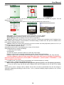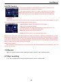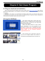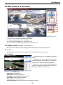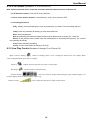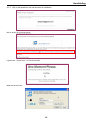
1
DVR
Digital Video Recorder
USER’S MANUAL
HANDLEIDING
351.124
User Manual
CONTENTS
Chapter 1: DVR Features...................................................................................................................................................... 2
Chapter 2:Layoutt................................................................................................................................................................. 3
2.1 Front Panel ....................................................................................................................................................................... 3
2.1.1 4-CH Front Panel (Details please refer to the real product).................................................................................... 3
2.1.2 8-CH Front Panel (Details please refer to the real product).................................................................................... 4
2.2 Rear Panel......................................................................................................................................................................... 4
2.2.1 4-CH Rear Panel (Details please refer to the real product) ..................................................................................... 4
2.2.2 8-CH Rear Panel (Details please refer to the real product) ..................................................................................... 5
2.3 Remote Control ................................................................................................................................................................. 6
Chapter 3: DVR Installation ............................................................................................................................................... 7
3.1 Hard Drive Installation ..................................................................................................................................................... 7
3.2 Camera and Monitor Connection ..................................................................................................................................... 7
3.3 Power Supply connection .................................................................................................................................................. 7
Chapter 4: DVR Boot up ....................................................................................................................................................... 8
4.1 System Initialization .......................................................................................................................................................... 8
4.2 Main Interface................................................................................................................................................................... 8
Chapter 5: DVR Menu ............................................................................................................................................................ 8
5.1 Main Menu Preview .......................................................................................................................................................... 9
5.2 Main Menu ........................................................................................................................................................................ 9
5.2.1 Camera setup ....................................................................................................................................................... 10
5.2.2 Record setup......................................................................................................................................................... 10
5.2.3 Network Set........................................................................................................................................................... 11
5.2.4 Recording Search................................................................................................................................................. 13
5.2.5 Multi player ............................................................................................................................................................ 13
5.2.6 Device Management ............................................................................................................................................ 15
5.2.6.1 HDD Management............................................................................................................................................ 15
5.2.6.2 Alarm Set .......................................................................................................................................................... 16
Email Alarm Notification.............................................................................................................................................. 16
5.2.6.3 PTZ Setup ......................................................................................................................................................... 18
5.2.6.4 Mobile............................................................................................................................................................... 18
Mobile Phone Access.................................................................................................................................................... 18
5.2.6.5 Motion Detect ................................................................................................................................................... 27
5.2.7 System Function................................................................................................................................................... 28
5.2.7.1 Time Set ............................................................................................................................................................ 28
5.2.7.2 Password ........................................................................................................................................................... 28
User Manual
5.2.7.3 Video Setup....................................................................................................................................................... 28
5.2.7.4 Language........................................................................................................................................................... 29
5.2.7.5 Info.................................................................................................................................................................... 29
5.2.7.6 System Maintenance ......................................................................................................................................... 29
5.3 Menu Lock....................................................................................................................................................................... 29
5.4 Video Search.................................................................................................................................................................... 29
5.5 PTZ Control .................................................................................................................................................................... 30
5.6 Record ............................................................................................................................................................................. 30
5.7 Stop recording ................................................................................................................................................................. 30
Chapter 6: Net-Viewer Program ........................................................................................................................................ 31
6.1 Plug-ins download and installation ................................................................................................................................ 31
6.2 Log-in to NetViewer ........................................................................................................................................................ 31
6.3 Main Interface of Net-viewer .......................................................................................................................................... 32
6.3.1 Menu column......................................................................................................................................................... 32
6.3.1.1 Live ................................................................................................................................................................... 32
6.3.1.2 Replay ............................................................................................................................................................... 32
6.3.1.3. Setup ................................................................................................................................................................ 33
6.3.1.4 Log out.............................................................................................................................................................. 34
6.3.2 PTZ Control ........................................................................................................................................................... 35
6.3.3 Live Play Control .................................................................................................................................................. 35
Chapter 7: Specifications ................................................................................................................................................... 36
Chapter 8: Windows Vista User ........................................................................................................................................ 37
Chapter 9: Appendix ............................................................................................................................................................ 39
9.1 Operation Function Table ............................................................................................................................................... 39
9.2 Recording Alarm setting.................................................................................................................................................. 40
9.3 Troubleshooting............................................................................................................................................................... 40
9.4 Email server check list(The below info only for your ref.) ......................................................................................... 41
9.5 Usage Maintenance......................................................................................................................................................... 41
9.6 System connection Configuration.................................................................................................................................... 42
User Manual
Safety Instructions
1.
Use proper power source.
Do not use this product with a power source that applies more than specified voltage (100-240V AC).
2.
Never insert anything metallic into the DVR case.
Putting something into the DVR case can be a source of dangerous electric shock.
3.
Do not operate in wet & dusty area or use near water.
Avoid places like a damp basement or dusty hallway.
4.
Do not expose this product to rain or use near water.
If this product accidentally gets wet, unplug it and contact an authorized dealer immediately.
5.
Keep product surfaces clean and dry.
To clean the outside case of the DVR, use a cloth lightly dampened with water (no solvents).
6.
Provide proper ventilation.
This DVR has a built in fan that properly ventilates the system.
7.
Do not attempt to remove the top cover.
If there are any unusual sounds or smells coming from the DVR, unplug it immediately and contact an
authorized dealer or service center.
8.
Do not attempt to remove the top cover.
Warning: You may be subjected to severe electrical shock if you remove the cover of the DVR.
9.
Handle DVR box carefully.
If you accidentally drop your DVR on any hard surface, it may cause a malfunction. If the DVR doesn’t work
properly due to physical damage, contact an authorized dealer for repair or exchange.
10. Use standard lithium cell battery. (NOTE: Manufacturer has preinstalled battery.)
The standard lithium cell 3v battery located on the mother board should be replaced if the time clock does not
hold its time after the power is turned off. Warning: unplug the DVR before replacing battery or you may be
subjected to severe electrical shock. Properly dispose of old batteries.
11. Make sure there is good air circulation around the unit.
This DVR system uses a hard drive for video storage, which generates heat during operation. Do not block
air holes (bottom, upper, sides and back) of the DVR that cool down the system while running. Install or place this
product in an area where there is good air circulation.
1
User Manual
Chapter 1: DVR Features
Real time monitoring
Supports real time surveillance via Monitor
Saves Recordings
DVR saves real-time recording image to HDD
Backup Recordings
Supports DVR backup via USB flash drive and hard drive.
Playback Recordings
Supports DVR single CH and multiple CH playback of recorded files
Network operation
Supports remote surveillance by multiple users simultaneously
Alarm Setting
Supports HDD & video input alarm management and external alarm signal
inputs
Mouse Operation
Supports Mouse operation for faster menu navigation.
PTZ Control
Supports PTZ camera operations through RS-485.
List 1-1
Other Features:
H. 264 video compression format, supports D1, HD1, CIF resolution
ADPCM audio compression format
Windows Graphical interface
BNC and VGA video out ports
Supports remote live viewing via 3G mobile networks
Supports sending email alerts when motion is detected by system
Triplex (recording, playback and net transmitting at the same time)
Supports USB mouse, IR remote control operation
Rear USB2.0 ports for backup, upgrade and mouse operation.
Supports Double Encode bit network transmission
The video package time is adjustable
Multiple alarm record mode
Multiple language OSD
Supports auto maintenance
2
User Manual
Chapter 2:Layoutt
2.1 Front Panel
2.1.1 4-CH Front Panel (Details please refer to the real product)
Item
Key title/Indicator
1
Power Switch
2
Power indicator
3
IR Receiver
4
HDD indicator
5
Channel Select:
CH1 CH2 CH3 CH4
6
QUAD
7
Marks
Functions
Turn Power on and off
PWR
If the “Green” indicator is on the system is getting power
Receives signal from Remote Control
HDD
When the “Red” indicator flashes it means the hard drive
is being read or written to.
Select Single Channel Display
Display all cameras in Live display or playback mode
REW
Move Left / Rewind
8
PAUSE
Pause / play frame by frame
9
PLAY
Enter into pop-up Menu/Play
10
FWD
Move Right / Play Forward
11
STOP
Stop Playback; stop manual recording
12
REC
13
MENU/ESC
Enter into main menu or exit menu
14
Up
Move Up
15
SEL/EDIT
Enter into pop up menu; Select key / Edit
16
Down
Move Down
17
PTZ:
Start Manual recording
Move to PTZ control mode
List 2-1
3
User Manual
2.1.2 8-CH Front Panel (Details please refer to the real product)
1
Power Switch
11
PAUSE: Pause / Frame Play
2
PWR: PWR Indicator
12
PLAY: Play
3
IR receiver for Remote Control
13
FWD: Play Forward / Move Right
4
HDD: HDD Indicator
14
STOP: Stop Playback; Stop manual Recording
5
SEARCH: Recording Search
15
REC: Manual Recording
6
MUTE: Audio Mute key
16
MENU/ESC: Menu / Escape
7
CH-: Switch to previous channel
17
UP: Move Up
8
CH+: Switch to next channel
18
SEL/EDIT: Select / Edit
9
ALL: Preview all channels
19
DOWN: Move Down
10
REW: Rewind / Move Left
20
PTZ: Move to PTZ control mode
2.2 Rear Panel
2.2.1 4-CH Rear Panel (Details please refer to the real product)
Item
Physical port
Connection method
1
Video input
Connect CH1-4 ( BNC interface)
2
Video output
Connect monitor output ( BNC interface)
3
Audio inp ut
Connect CH1-4 audio signal input (RCA interface)
4
Audio output
Connect signal output (RCA interface)
5
Ethernet: Port
Connect intranet, internet (RJ45 interface)
6
VGA Port
Connect to VGA monitor
7
USB Port
Connect USB device (Flash Drive, Hard Drive)
8
USB Port
Connect USB mouse
9
RS-485/Sensor/Alarm
RS485/Sensor/Alarm interface (see pin outs below)
Power Port
Connect power supply - DC12V 3A
10
4
User Manual
2.2.2 8-CH Rear Panel (Details please refer to the real product)
1
CH1-8: Video inputs
6
Audio Output
2
Video Outputs
7
USB port: backup to Flash Drive & Hard Drive
3
Audio Input
8
Mouse port
4
LAN: LAN port for Network Access
9
RS-485/Sensor / Alarm port
5
VGA port
10
Connect power supply
8-CH: RS485/Sensor/Alarm port functions
4-CH: RS485/Sensor/Alarm port
functions (from left to right):
Pin 1-2:PTZ Control port
Pin 1:RS-485A
Pin 2:RS-485B
Pin 3-4: Sensor 1 input
Pin 5-6: Sensor 2 input
Pin 7-8: Sensor 3 input
Pin 9-10:Sensor 4 input
Pin 11-12:Alarm Output
(from left to right):
Pin 1-2:PTZ Control port
Pin 1:RS-485A / Pin 2:RS-485B
Pin 3-4:Sensor 1 input
Pin 4-5:Sensor 2 input
Pin 6-7:Sensor 3 input
Pin 7-8:Sensor 4 input
Pin 9-10:Sensor 5 input
Pin 10-11:Sensor 6 input
Pin 12-13:Sensor 7 input
Pin 13-14:Sensor 8 input
Pin 15-16:Alarm Output
5
User Manual
2.3 Remote Control
1
2
Channel Select 1-8 ; Numeric key
1-8
Numeric Key
9、0
Preview all Channel
3
ALL
4
Menu
5
▲
Up Key
6
▼
Down Key
7
◄/
Left / Right Key
8
SEL
Select Key/ Edit Key
Enter/Exit Main Menu
9
Rewind key
10
Play Key, Enter to recording search menu
11
Forward Key
12
●
Manual Recording
Pause / Frame Play
13
14
■
Stop manual recording; Stop Playback
15
Audio
Undefined
16
Mute
Undefined
Mouse Operation
You can use a mouse instead of front panel buttons or remote control.
In menu lock mode, Enter into pop-up menu and clicking any sub menu to pop up Log-in
window; on menu unlock mode, enter into pop-up menu, and then clicking left key to
enter into any sub menu directly.
After entering main menu, clicking left key could enter into any sub menu; On[Detailed
file] menu mode, clicking left key could playback one recording file.
Click left key of
Mouse
Change the status of check box and motion detection area.
Clicking combo box to access pull-down menu
By clicking left key you can adjust Color control bar and volume control bar.
By clicking left key you can select values in edit boxes or pull-down menu and supports
Chinese word input, special symbol, numeric and character input, use instead of
[Enter] or [Backspace
]
In the [Detailed file] menu mode, clicking left key will playback one recording file.
Click right key of
Mouse
Double-click Left
key of Mouse
In live display mode, clicking right key will display pop-up menu (shown as Picture 5-1).
In Main menu or sub menu mode, clicking right key will exit current menu.
In live display or playback mode, double-clicking left key will maximize the screen.
Moving Mouse
Select menu item
Sliding Mouse
On motion mode, sliding mouse will select motion area; On [Color set] menu mode,
sliding mouse will adjust color control bar and volume control bar.
List 2-3
6
User Manual
Chapter 3: DVR Installation
3.1 Hard Drive Installation
Caution: Please do not Install or take out hard drive when DVR is running!
(1) Remove screws and open DVR upper cover carefully;
(2) Insert Power Cord and data cable into Pin of hard drive securely;
(3) Put the upper cover back carefully, re-attach screws.
3.2 Camera and Monitor Connection
Connect camera cable to video input of DVR, and from video output of DVR to Monitor via BNC connector
(Refer to section2.2-Rear Panel); or
If the camera is a PTZ speed dome, you could connect RS485 A & B to the according port of DVR
respectively (refer to system figuration on Chapter 8).
3.3 Power Supply connection
Please only use the power adapter supplied with the DVR .
7
User Manual
Chapter 4: DVR Boot up
4.1 System Initialization
After connecting the power adapter and turning
On the power button, the system will boot-up and start
initializing.
Picture 4-1
4.2 Main Interface
Picture 4-2
After finishing system initialization the system will enter into main
interface. Picture 4-2 is the main interface displayed by system, which
is showing no video input status. Once there are video inputs, the
interface will display live images from the cameras. In main interface
mode, if you use the mouse to double-click the live image of any
channel, the image will be maximized to full screen, by double-clicking
again, the display will be come back to quad mode displaying all
cameras; clicking the right button of the mouse, will enter into Pop-up
Menu; by clicking the left button of the mouse, you select menu items;
when clicking any area outside the menu, you will exit the Pop-up
menu.
Chapter 5: DVR Menu
Pop-up Menu
After finishing system initialization, click right key of mouse on main
interface mode to enter into Pop-up Menu. Now you could proceed parameter
setting and operate for Main Menu, Menu Lock, Video Search, PTZ, Start
record, Stop Record and also operate for Start Cruise after successful PTZ
parameter setting etc.
Picture 5-1
8
User Manual
5.1 Main Menu Preview
Color set
Camera
Dwell time display
Recording
Network
Search
Playback
Rec. Search
File List
Main Menu
HDD Management
Alarm Setting
Device
Management
E-mail setting
PTZ Setting
Mobile
Motion
Area setting
Time Setting
User password
Video Setting
System
Language Select
System Information
System Maintenance
5.2 Main Menu
Picture 5-2
After clicking right button of mouse, pop-up menu will be displayed
on the screen. You can click [main menu] button on pop-up menu
to enter into Main menu interface (Shown as Picture 5-2). You can
also use the Menu button on the front panel to bring up the window,
when using the front panel buttons use the FWD and REW button
to move in the menu, and the SEL button to select the icon. You
use the ESC button to return to previous window. In Main Menu
mode, you can control device management settings, such as
Camera, Recording, Network, Recording search, HDD, Alarm, PTZ
Control, Mobile Phone & motion detection etc, you can also set
system function settings, such as Time setting, User password,
Audio/Video setting, Language select, and access system information, system maintenance etc.
9
User Manual
5.2.1 Camera setup
Go to [Main Menu
Camera] to set up the name display
and position display of each channel (Shown as Picture 5-3), You
can also adjust image brightness, saturation, contrast and hue
settings of each channel after entering into [Color] Menu and set
up whether each channel can be previewed or not under Live
display and/or Recording mode.
Please note that the name of each channel supports up to
eight characters.
Picture 5-3
Below is the Color Menu where you can adjust image
brightness, saturation, contrast and hue parameters of each
channel.(shown as picture 5-4)
Picture 5-4
Explanation:
1、The modifications will be available after clicking [APPLY] button on the bottom of the sub-menu windows and
being prompted to save and then clicking [ok] button.
2、If you want to cancel the modification, click [Exit] button to exit the menu.
3、When clicking [DEFAULT] button, all system default values will be reset to default value.
4、System default value indicates the value pre-set at the factory.
Click [AUTOSEQ] button to start auto rotation function.
(setting sub menu shown as Picture 5-4A. After starting auto
rotation function, system will auto rotate the video images among
CH1, CH2, CH3, CH4 and Quad in turn.
Default rotation time: 5 second
Settable time range: 0~10 second
Picture 5-4A
5.2.2 Record setup
Click [Main Menu] [Record] to enter into [Record Setup]
menu (Shown as Picture 5-5)
Functions:
1、The [Rec Mode] button allows you to setup recording 24
hours, on motion, or on a set schedule.
2、[PACK time] indicates maximum continuous time length of
recorded
(15, 30,status
45, 60(on/off)
min). of each channel, it also allows you
The [Record Setup] menu allows you
set upfiles
recording
Picture
5-5 resolution and quality, and turn audio on/off. This menu also allows you select recording
setup recording
image
mode (recording after power on and scheduled recording) and recording file length.
10
User Manual
Once a channel is set to “on” the channel can record, if it is set to “off” the video from the channel will not be
recorded. Resolution options are D1, HD1 and CIF; and Quality options are Best, Good and Normal.
When Audio is set to “On”, system will also record audio from the channels and will have audio output on
playback mode; if it is set to “off” you can not record audio and will have no audio output available on playback
mode.
To record 24 hours a day set the Rec Mode to Always. To record on motion or a set schedule, select Time
Schedule Record and click the “Schedule” option, the Schedule interface will open as shown in (picture 5-6):
Picture 5-6
Recording options include All, CH-1, CH-2, CH-3, CH-4
respectively. Please click the channel you need, the channel you
select will be highlighted in “Blue” unselected channels will be “Grey”.
To setup weekly schedules, click on the box of the recording
status you want (Alarm, General, or No Record) and then click on
each box in the schedule time line that you want this method to apply
to. You can use the [From – To] pull-down menus and Copy button to
copy settings from one day to another day or all days. After you
complete the schedule you activate it by clicking the [Apply] button.
You can also click on the Default button to use the system defaults. The system default settings are:
Hr01:00 am-07:59 am : No recording
Hr08:00 am-18:59 pm : Normal recording
Hr 19:00 pm- 00:59 pm : Alarm recording
Explanation: Under the recording Set menu and recording search menu, original color stands for no
recording, “Red” stands for alarm recording, “Green” stands for normal recording and “Blue” stands for the
channel and date you have selected.
5.2.3 Network Set
Enter into [Main Menu Network Set] to proceed network set (Shown as picture 5-7):
After selecting network mode - such as DHCP、PPPOE and
static allocation and setup web port, you could visit DVR remotely
via network.
Picture 5-7
11
User Manual
When selecting DHCP, DHCP server will allocate DVR IP address automatically.
When selecting PPPoE, you need to input user and password
provided by ISP supplier and set up web port (details please refer
to the below picture 5-8).
Picture 5-8
When selecting static allocation, you need to setup IP address,
net-mask, gateway and web port (shown as picture 5-9).
Picture 5-9
Picture 5-9
If you apply for DDNS service and set up net parameter of
DVR accordingly, you could visit DVR remotely via IE browser.
(shown as picture 5-10)
Picture 5-10
If you need to visit DVR via Internet, you should setup the
inflection of video port at the public Router located in the DVR
(shown as Picture 5-11).
Host Port: 9000
Web Port: 8080
LAN IP address of DVR: 192.168.1.101
Input http:// router IP:8080 (192.168.1.101:8080) to you
computer IE browser,then you will visit your DVR freely.
Picture 5-11
12
User Manual
5.2.4 Recording Search
Click [Main menu
search] to enter into [Video Search] menu (shown as the below picture 5-20).
Searched playback:
If you input specific date and click [Search], you will find all the
recordings for that day. When you select [Date] item, you will
playback the recordings in 4 channel mode; or, click [File list] button
to display File list interface, where you can playback or backup the
file you selected. See File List heading below.
Picture 5-20
You can play video Forward at 2x, 4x, and 8x speeds, Slow play at 1/2x, 1/4x, and 1/8x, normal play, pause
and play frame by frame using the playback control bar, and adjust volume by clicking or sliding tune control bar.
When playback has finished, system will return to previous menu.
File list
On the [Video search] menu mode, click [File list] to pop up the sub-menu shown below as Picture 5-21.
This option will allow you to view all of the available files by channel and type (all, normal, or alarm).
You can select a file and push the SEL button to playback the file, or use the FWD button and down button to
select the option and backup the recording file you selected. You can also put a checkmark in the box at the end
of multiple files if you want to backup more then one file.
First:Indicates the first page of recording history you have
searched. When you view other pages, clicking [First] button brings
you back to Page one.
PRE (Previous page): When viewing event list, clicking
[Previous page] button will take you back to page before the one you
are currently viewing (except the first page).
NEXT (Next page): When viewing event list, clicking [Next page]
button will take you to the page after the one you are currently viewing
(except the last page).
Picture 5-21
LAST (Last page): Indicates the last page of recording history you have searched. When you view other
pages, clicking [Last page] button will take you to the Last page.
ALL (Select All): Allows you to select all the events on the current page.
INVERSE (Select Invert): Allows you to select other events on the current page except those you have
currently selected.
Recording File Backup
If you want to backup one recording from the file list, you just select the recording and click [Backup] button.
When the backup is completed you will be notified. Please click [OK] button to save your backup (shown as
Picture 5-22).
Explanation: Backup file will be in H264 format, you can convert it to AVI format using the Multimedia Player
program that comes with the DVR or through the net-viewer program, so you can use any player which supports
AVI format.
Picture 5-22
Picture 5-23
5.2.5 Multi player
1、Copy backup file to your PC.
13
User Manual
2、Open multimedia player and click [File
Local (F)] to find/select the backup file, and then click [open]
button
Note: the file type you have selected should be *.264 format.
Picture 5-25
Picture 5-24
3、Open backup file:
(1)、Click [Play] menu (P) on the top of multimedia player
interface to select playing the backup file;
Picture 5-26
(2)、Click pop-up menu button
on the bottom of multimedia player and [Play-
] button, then the
backup file will be played on the according channel.
(3)、The Menu brief on the bottom of multimedia player:
recording date for the current backup file shown as right corner;
Date:
24H recording time: lie under [Date] menu. Black number button stands for current recording playback
is normal recording for the time line.
0~60 Minute recording time quantum: Green part on play processing bar stand for recording length for
one hour recording.
Recording date and time processing for the current recording file
1
2
3
4
5
6
7
Play
Previous recording file
Pause
Stop
Previous frame / Next frame
Slow play, Normal play, Fast Play
Next Hour
14
10
11
12
13
14
15
16
All the windows
Add window
Start
Cut
Delete
Convert AVI
OSD
User Manual
8
9
Capture picture
Reduce window
17
18
Mute switch
Volume adjust
4、Please refer to the below [Video on] setting procedure (System default - video for every channel is on)
Setting Video
play
setting
Normal
Bar Select the channel you want to display
to play the video Apply OK
video
Select
Picture 5-27
Picture 5-27A
5、Refer to the below for [Audio on] setting procedure. (Setting parameter will be available after re-starting
multimedia player after [Audio on] set up.)
Setting Audio channel setting
Normal video Bar Select the channel you want to playback the audio Select
the channel has audio files Apply OK.
Picture 5-28B
Picture 5-28A
After successfully setting the above, when you playback the current channel, you can open the channel’s
audio function at the same time as the video
5.2.6 Device Management
Options in device management include Hard drive,
External Alarm, PTZ control, Mobile Phone Monitoring, and
Motion Detection.
Picture 5-29
5.2.6.1 HDD Management
Click [Main Menu Device
HDD] to enter [HDD
Management] menu (shown as Picture 5-30)
Picture 5-30
15
User Manual
When you install a HDD, the system will automatically detect
if HDD is formatted or not; If HDD needs to be formatted, HDD
status will be shown as “Not format”, otherwise, the HDD status
will be shown as “Normal” (refer to Picture 5-31)
TOTAL SPACE: Indicates total space available on Hard
Drive.
FREE SPACE: Indicates unused space available on the
Hard Drive.
USEABLE REC TIME: Based on current image
Picture 5-31
detail/quality and frame rate, system will show you how
Recording time you have left on the Hard Drive.
OVERWRITE: If you select “on” the system will automatically overwrite the oldest recordings once the hard
drive is full; if you select “off”, recording will stop once the hard drive is full.
HDD FORMAT: You use this option to format the hard drive, you can not record files to the hard drive until it
has been formatted. Click [Format HDD] button to start formatting. When selecting [Format HDD] option the
system will prompt you – “Format HDD will loss all the data, do you confirm?” ; click “OK”, system will prompt
you – “Is formatting…” and “successful format”; and then system will restart automatically.
USB FORMAT: Use this option to format USB devices.
5.2.6.2 Alarm Set
Click [Main Menu Device
Alarm] to enter into [Alarm setup]
menu to setup Alarm warnings (shown as Picture 5-32).
I/O STATUS : Options include NO (Normal-open), NC
(Normal-close) and OFF. Set to “Normal-open” if you use external
sensor alarms that are normally open, Set to “Normal-close” if you
use external sensor alarms that are normally closed, set to “off” if you
are not going to use external sensor alarms. You can use the DVRs
Picture 5-32
not external sensors to record on motion detection.
HDD LOSS: Options are On and Off. If you select On there will be a buzzer sound and “H” sign on screen
when HDD is not detected or not formatted; on the contrary, if you close the function, there is only “H” sign to
indicate HDD not found, but no alarm sound when HDD not found or not formatted.
HDD SPACE: Options are On and Off. When the alarm function is on, there are alarm sounds when the
HDD is running out of space; when the function is off, there are no alarm sounds.
VIDEO LOSS: Options are On and Off. When the function is on, system will issue alarm sound and display
video loss on the preview interface; when the function is off, system will have no alarm sound, but the preview
interface will display video loss.
ALARM MANAGE:Alarm Output(0s,10s,20s,40s,60s)、Buzzer time (0s,10s,20,40s,60s) and alarm duration
time(0s, 30s, 1minute,2minute,5minute)。
Alarm Type
Function
Video Loss
Sends alarm when DVR can’t receive video signal (such as camera damage, cable broken or
Motion Detection
When an object moves into motion detection area, alarm will be triggered. You can adjust sensitivity
I/O Status
System can convert alarm signal triggered by external sensor into signal identified by system.
HDD loss
When Hard Drive is not detected (HDD damage, power supply malfunction), or HDD auto-overwrite is
List 5-1
Email Alarm Notification
(to send notice to email account when motion alarm is triggered)
16
User Manual
Click the [Email setup] menu to enter into its sub menu
(shown as Picture 5-33).
Picture 5-33
On the [Email setup] mode, refer to its parameter setup
shown as picture 5-34 when setting email alarm to “on”.
SSL: is a security link transport protocol. You can encrypt your
communication info (including your email) using SSL to prevent hackers from
monitoring your email or communication info and even your password.
Picture 5-34
Please set SSL to “On” via Gmail.com server, and set to “Off” via other mail server.
If your setting is still not right, please contact the web site where you have applied for your email box to get
SMTP server and SSL of mail box.
Picture 5-35
SMTP Port: indicates sender port of SMTP server. Generally the SMTP port value is 25, but
e are exceptions, for example, SMTP port of G-mail server should be 465.
ther
SMTP server: indicates server address you use.
Sender email: indicates sender’s email address. The email address should be consistent with the server
you use. That is to say, when you use email address – [email protected], the according server should be
smtp.gmail.com.
Receiver address: indicates receiver’s email address. The email address is used to receive image t
ransmitted from motion detection alarm of DVR. Please clear the images you have received as
soon as possible to avoid overloading your email account. For detailed SMTP protocols settings
refer to the below picture 5-35A.
Picture 5 35A
17
User Manual
5.2.6.3 PTZ Setup
Enter into [Main menu Device PTZ Setup] to select
the channel you want to control and set PTZ protocol
(Pelco-D or Pelco-P), Baud Rate (1200, 2400, 4800, 9600),
Stop bit (1, 2), Parity Check (None, Odd, Even Mark Space),
Address Code and Cruise status respectively. Please note
the above mentioned channel settings must match the
settings of the PTZ camera.
Picture 5-36
5.2.6.4 Mobile
Click [Main menu Device Mobile] to enter into [Mobile]
menu.
User Name: indicate user name of DVR.
User password: indicate user password of DVR
Server port: Mobile monitoring port. Setting range is between
1024 and 65535. Please note that
Picture 5-37
Explanation: Please connect DVR to Internet before
setting DVR port number and the server port no is not equal to
network menus.
Mobile Phone Access
The DVR is currently compatible with mobile phones running Windows Mobile and Symbian operating
systems on 3G networks.
Before you can access the DVR from a mobile phone you need to setup the Network Configuration on the
DVR. Go to section 5.2.3 Network Setup on page 14 of the product manual for instructions on how to do this. You
also need to go to the Main Menu then Devices then Mobile and enter your user name and password, and set the
Server Port to 18600. This port also needs to be forwarded to the IP address of the DVR along with the ports from
5.2.3 Network Setup.
Explanation: You can only see one channel at a time when viewing from a mobile phone. The speed
of the display depends on the speed of the internet connection.
When accessing from a mobile phone with Windows Mobile operating system, use the following
procedure:
1. Webcam installation
First you need to install the webcam program that is included on the CD that comes with the DVR by
copying the “QQeye.CAB” file to the mobile phone. You can do this by attaching the mobile phone to a computer
and copying the file from the CD to the memory card on the phone, or by copying the file from the computer to the
phone’s memory card through a memory card reader or through a Bluetooth connection.
Pic 3
Pic 1
Pic 2
2. Click the windows mobile folder (red box in Pic 1) and choose the file
QQeye” Select the file which will open the window in Pic 3. The file is generally faulted to save as Device, direct
to phone, (shown in Pic 3) but you can save it to Device or Storage Card.
18
User Manual
3. Choose storage location and click [Install] button (red box in Pic 3) to start the installation (please refer to
display in Pic 4 below)
Pic 6
Pic 5
Pic 4
4. After installation finishes, click the icon named QQeye (red box in Pic 5) to run the program. This will
display the program screen in Pic 6.
5. Settings: Click [Setting] button (red box in Pic 6) to enter the Setting menu shown as Pic 7
Pic 9
Pic 7
Pic 8
User name: same as user name setup in DVR under Menu, Devices, Mobile
Password: same as password setup in DVR under Menu, Devices, Mobile
Server address: Public IP address of router DVR is connected to.
Web port: Same as the Server Port you setup in the DVR, it needs to be forwarded to the IP address of the
DVR, setting range is between 1024 and 65535, the default setting is 18600. Note: this port is in addition to the
ports used for standard remote access.
Channel: Select the channel from the DVR you want to monitor and click [OK] button (red box in Pic 7) to
display the screen in Pic 8 and start video connection.
6. Main interface operation (Pic 8)
Click [Disconnect] button to stop displaying live image of the channel.
Click [Setting] button to modify the settings.
7. Video connection Display
Normal Mode:
You will find network connection status info under the video image:
Display on the left corner: Network transmission speed, Frame rate and Resolution.
Display on right corner: percentage of buffer display, Connection success,Connection fail, Play and Stop.
Function of Buttons under the video image from left to right: PTZ control (Left, Right, Up and Down),
area select (Zoom out and Zoom in), Focus (Add “+” and deduct “-”) and Iris (Add “+” and deduct “-”) and
Snap to capture screen image.
8. Display mode: You can convert normal display into full-screen display by clicking
the screen on the mobile phone (displayed as Pic 9)
When accessing from a mobile phone with Symbian operating system, use the following procedure:
1. First you need to copy the file with suffix “QQeye.CAB” that is included on the CD disk to the mobile
phone.
Copying file is save to storage card by default, and the file can also be transmitted from the CD through a
computer by Bluetooth technology to save to Inbox (Pic 1). Select the QQEye program (red box in Pic 1) which
will display Pic 2.
19
User Manual
2. Select the QQEye icon in this window (red box in Pic 2) to install it, this will display Pic 3).
Pic 1
Pic 2
Pic 3
After the phone finishes preparation it will display Pic 4 asking for permission to install the program. Select
the Yes button (red box in Pic 4). This will display the window in Pic 5.
``
Pic 5
Pic 4
Pic 6
3. Click the Continue button (red box in Pic 5) on the information box displaying the program and current
version. This will display the window in Pic 6.
4. Next choose where you want to install the program, to phone memory or to the memory card, and click on
the Select option (red box in Pic 6). This will display the window in Pic 7, click on Continue (red box in Pic 7)
which will display the screen in Pic 8 and tell you it is installing the program (red box in Pic 8).
Pic 7
Pic 9
Pic 8
5. Once the installation is complete the window in Pic 9 will be displayed to tell you that installation is
completed. Then you can go to the Applications folder and select the QQEye program (white box in Pic 10) and
click on the Open option (red box in Pic 10) to display the settings menu. After you complete the settings and click
on the Done button (red box in Pic 11) the Video window in Pic 12 will be displayed.
Open
Pic 10
Pic 11
Default Access Point:
Input the access point. System default for the access point is GPRS connection.
20
Pic 12
User Manual
Server Address:
Input the public IP address of the router the DVR is attached to (refer to section 5.2.3 Network Setup on page
14 of the product manual).
Server Port:
Web port: Same as the web port setting on the DVR, you need to forward this port from the Router to the
DVR. Setting range is between 1024 and 65535, the default setting is 18600. Note: this port is in addition to the
ports used for standard remote access.
User Name:
Same as user name setup in DVR under Menu, Devices, Mobile
Password:
Same as password setup on DVR. (Please press Function key to save the password, left soft key won’t be able to
save the password)
Channel:
Select the channel you want to monitor and click [OK] button to start video connection
Network connection status: percentage of buffer display, connection success, connection fail, play and
stop.
Channel select, PTZ control, Zoom in/out, Focus and Iris
Play/Stop, Full screen/ Normal Display, Capture,
Parameter setting and Exit【】
By clicking on the image you can see it full screen as in Pic 13
Pic 13
Step 1: Download iTunes
Visit Apple website http://www.apple.com/itunes/ to download & install the iTunes.
Step 2: Download & install surveillance software “Aplayer”
2.1 Register iTunes Store
2.1.1 Run the installed iTunes, you might need to create an account to visit iTunes store firstly. Move to
the menu “Store”, and click the option “Create Account”.
21
User Manual
2.1.2
Continue
2.1.3
Select & continue
2.1.4
Fill in your personal info & continue.
22
User Manual
Please note that the options of Payment Method are different from different regions, please select
another payment method. Don’t worry, “Aplayer” is a free software & you don’t need to pay for it.
2.1.5
Finished the register, and go to your email box to verify your account.
Click the link included in the email message.
It will connect to the iTunes store and turn to iTunes interface.
Sign in your account.
23
User Manual
The register of your iTunes store account has been done.
2.2 Authorize Computer
You need to authorize your computer with the registered ID.
Move to the menu “Store”, and click the option “Authorize Computer”.
Input your registered ID & password, then click Authorize button.
2.3
Download & install “Aplayer” into your iPhone
24
User Manual
2.3.1 Click iTunes Store(1), then input “aplayer” into the search bar(2) on the right upper corner and
press Enter.
2
1
You will find the Aplayer icon displayed as below.
2.3.2
file.
Click the icon and it will turn to the download page. Click the “GET APP” button to download the
You will find the downloaded file on the directory of Application
25
User Manual
2.3.3 Connect your iPhone to the computer, you will find your Device displayed on the left sidebar.
Select the DEVICES ID(1), and then click “Applications” option(2). Select the “Sync Applications” &
“Aplayer” (3) and then click “Sync” button(4).
2
3
4
1
* The devices ID is different from different iPhones.
After finishing the sync, you will find the Aplayer Icon on your iPhone.( Picture I-01)
Ⅰ
Ⅵ
Picture I-01
Step 3: Setup & run “Aplayer”
Main interface of Aplayer & function keys: ( Picture I-02)
. Direction keys of PTZ control
. Zoom+ & Zoom. Focus+ & Focus. Iris+ & Iris. Channel selection keys
. Play & Pause
. Snapshot
. Full screen
. Next group of channels
. Setup
26
Ⅱ
Ⅲ Ⅳ
Ⅶ
Ⅷ
Picture
I-02 Ⅸ
Ⅴ
Ⅹ
User Manual
3.1 Access information setup
Turn into setup menu, and fill in the information according to your DVR Mobile settings.
Server IP: input the IP address or domain name to visit your DVR
Port: same with the server port you have set in your DVR mobile settings
User ID: same with the user name you have set in your DVR mobile
settings
Password: same with user password you have set in your DVR mobile
settings
After finishing the settings, press “Back” button to the main interface.
Press Play button to start mobile surveillance.
Press channel selection keys to switch camera picture.
5.2.6.5 Motion Detect
Click [Main Device Motion] to enter into the [Motion Detection]
menu to setup motion detection recording.
The [Motion detection] Menu has three sections, including
Channel Status, Sensitivity and Motion area.
Channel STATUS: This option allow you enable motion detection
on any channel.
Picture 5-38
SENSITIVITY: This option allows you to set sensitivity level of
motion detection from 1 to 4 with 4 being the most sensitive.
MD AREA: This option allows you select the area you want to be
sensitive to motion. The channel is separated into a 13*10 area. When
any object moves into the motion detection area, and the area where
the object is located is displayed in red recording will be triggered. In
the semi-transparent area the motion detection is off.
Picture 5-39
27
User Manual
5.2.7 System Function
The [System] Menu includes the below sub-menus: Time
Set, User Password, Audio/Video Setting, Language select,
System Info and System Maintenance.
After entering into the [System], you can configure the
system to meet your needs.
.
Picture 5-40
5.2.7.1 Time Set
Click the [Main menu System Date/Time] in turn to Enter
into the time setup menu shown as Picture 5-41 to not only
modify system date, time, date/time format and time zone, but
also setup DST (day saving time) status and mode.
Picture 5-41
5.2.7.2 Password
This option allows you set the device ID for the DVR and set
the system password if you want to use one. The new passwords
will be available after clicking [APPLY] button.
.
Picture 5-42
When you set Password Enabled to “ON” (shown as Picture
5-43), you can setup a user password and administrator password
respectively. The password supports up to 6 characters.
Picture 5-43
5.2.7.3 Video Setup
Click [Main Menu System VIDEO] to setup Video, here you can
set Camera system(PAL, NTSC)In the USA we use NTSC.
You can also set the resolution for the VGA video out port. Your
options are 600x480, 800x600, or 1024x768, or 1280x1024.
Picture 5-44
28
User Manual
5.2.7.4 Language
Enter into [System Language] menu to select the language
you want to use on the DVR (shown as Picture 5-45) and click
[APPLY] button. The selection will be available after system Auto
restarts.
Picture 5-45
5.2.7.5 Info.
Click [Main Menu System Info] to enter into [System
Information] menu to view system info, including Device type, Software
(firmware) version and MAC address etc.
Picture 5-46
5.2.7.6 System Maintenance
This option allows you reset the DVR to factory default settings,
update system software (firmware), and set system auto-maintenance.
Click [Main menu System Maintain] to enter into the [System
Maintain] menu (shown as Picture 5-47).
When opening auto-maintain function, you can setup system to restart
regularly.
Picture 5-47
5.3 Menu Lock
As a system safety feature you can click [Menu Lock] menu to
lock menu when leaving the DVR. If you want to login to the DVR,
you would input device code and password (refer to the Menu
Locking interface- Picture 5-48).
Picture 5-48
Explanation: User only has the authority to search
recordings, but Administrator has full authority over Main
Menu operations
5.4 Video Search
Click pop-up menu video search to enter into [Video Search] menu you search files and playback recordings.
For more information on this operation refer to the previous section 5.24.
29
User Manual
5.5 PTZ Control
We introduced setting PTZ parameters previously in chapter 5.2.6.3.
Here we will discuss how to operate PTZ controls.
Click pop-up menu to show PTZ option and enter into PTZ control
interface (shown as Picture 5-49). You can now click Z+&Z- keys to zoom In
or out, click F+&F- keys to control camera focus and click I+&I- to adjust iris.
Picture 5-49
Cruise Set
Open auto cruise function on PTZ setting menu if you want to setup cruise function (system default: on), and
set up cruise channel, cur point and total quantity and stop time etc.
Channel select: select the channel with the PTZ camera
Total: set up presetting bit quantity
Cur Point: System has default starting (current) cruise point as 01. You
can use this option to set additional cruise points.
Stop time: sets the pause time at each stop.
GOTO:select this option to go to specific preset points
Set: save the preset point. After setting channel and setting the position by adjusting PTZ direction key you click
[Set] button to setup the pre-set point. Please note you will click the [Save] button to finish the setting successfully.
If you want to combine Zoom, Iris, Focus and direction keys into the pre-set setting, please return to previous
menu (shown as Picture 5-56) to add additional settings, and then enter into Cruise Set again and click [Set] and
[Save] to make sure your setting is setup successfully.
Clean: remove settings.
Note: this DVR model supports up to 100 pre-set points. But actual quantities may be restricted by the PTZ
camera you are using.
5.6 Record
When you want the system to start recording click [ Rec ] button to start manual recording.
5.7 Stop recording
If you want to stop manual recording click [Stop Record.] menu or [Stop] button
30
User Manual
Chapter 6: Net-Viewer Program
6.1 Plug-ins download and installation
Open IE browser and input IP address and web port of DVR, such as http://172.18.6.202:80/ and confirm to
download and install webcam. If your computer is connected to internet, computer will auto download and install
the webcam.
Reminder: If the webcam is not downloaded successfully, please check if your browser’s safety level or
firewall setting is too advanced. Also refer to section 5.2.3 Network Setup to make sure network configuration is
correct, ports are forwarded correctly, and ActiveX is enabled.
6.2 Log-in to NetViewer
After webcam installs plug-ins, please select log-in
language (Chinese or English) and enter password and
click [Log-in] button, and now you can view DVR
remotely through NetViewer.
Please note default password is empty. System
allows Administrator to set new password as per
instructions in section 5.2.6.2 - [Password set] menu.
Picture 6-1
Note: If you want to delete old IE webcam at DVR
system update, run the command characters:
“regsvr32/u dvrocx.ocx”
After successful Log-in to Net-viewer, system will
enter into live display interface and connect to
audio/video feed automatically (shown as Picture 6-2).
Picture 6-2
31
User Manual
6.3 Main Interface of Net-viewer
Picture 6.3
Log in Net-viewer and show the interface as follows
6.3.1 Menu column (Section 1 on Picture 6-3)
6.3.2 PTZ Control (Numbers 2, 3, 4 on Picture 6-3)
6.3.3 Live Play Control (Numbers 6 through 10 on Picture 6-3)
6.3.1 Menu column (Section 1 on Picture 6-3)
Menu column include [Live] menu, [Replay] menu and [Setup] menu and [Logout] menu.
6.3.1.1 Live
After Logging-in to system, system will enter into Live display (shown as Picture 6-3).
6.3.1.2 Replay
This option allows you to playback recordings
remotely.
First select the day, channel and type and
proceed searching and refreshing; second select
any event from search result list to playback.
Please note you can control playing speed by
sliding the playing-control bar on the bottom of
the interface (shown as Picture 6-4).
Picture 6-4
Play button: [Play]/[Pause]
Stop button: stop playing recording.
F.F. button: fast forward playback recording
Slow button: slow playback recording.
Next Frame: play frame by frame.
264 TO AVI button: convert file from H.264 format to AVI format
32
User Manual
The native format of the backup files is H.264, you can convert H.264 format into more familiar AVI format by
clicking the key of 264 to AVI.
6.3.1.3. Setup
Click [Setup] menu to enter into its sub menu, including [Recording Mode] menu, [Alarm Mode] menu, [PTZ
Control] Menu, [Network Setting] menu, [System Setting] menu and [Host Info] menu.
Explanation: Only when DVR is on the status of live display, you could modify and save its parameters
remotely at this moment, the settings are available. The modification method to DVR via Net-viewer is the same
as local adjustment of DVR.
① Record
Enter into sub menu – [Recording Mode] menu, you can
select on/off for every channel, and adjust recording
parameters (resolution, quality, audio, REC mode and
Schedule) remotely via Net-viewer.
Picture 6-5
Click the [Schedule] menu to enter into its sub menu
(shown as Picture 6-6).
Remote setup methods are the same as local DVR
setup. Please refer to Section 5.2.2 Record Setup
Picture 6-6
② Alarm
Picture 6-7
Click [Alarm] menu to enter into its sub menu (shown as
Picture 6-7).
You can set I/O alarm for every channel, motion detection
alarm, motion recording, motion trace, motion sensitivity, video
loss alarm, HDD not enough space alarm, HDD not found
alarm and alarm output time etc.
For details on setup method please refer to section
5.2.5.2.
33
User Manual
System allows you setup motion detection settings for each channel
of DVR remotely (shown as Picture 6-8)
Picture 6-8
③ PTZ Control
Click [PTZ control] to setup PTZ cameras. Remote
setup methods are the same as local DVR setup.
Please refer to Section 5.2.5.3 (shown as Picture
6-9).
Picture 6-9
④ Network
Click [Network] to enter into [Network]
menu. Remote setup methods are the same as
local DVR setup.
Please refer to Section 5.2.3. – Network
Set.
Picture 6-10
⑤ Setting
Picture 6-11
Click [setting] menu to enter into the menu interface
(shown as Picture 6-11);
Click […] button to preview net-viewer recording
saving path and screen capture saving path.
The menu also allows you to set a lower bandwidth for
Internet video transmission, set user password, turn
daylight saving time on/off, etc.
⑥ Host Info
Click [Host Info.] to enter into the sub menu (shown as
Picture 6-12). Here you can check Usage rate of HDD,
available recording time, software version and MAC address.
6.3.1.4 Log out
Picture 6-12
Log out of the system.
34
User Manual
6.3.2 PTZ Control (Numbers 2, 3, 4 on Picture 6-3)
Note: below-mentioned series no will be consistent with the remark no shown as Picture 6-2.
○,2.PTZ direction control: Control PTZ moving direction
○,3.Zoom, Focus and Iris Control: control direction, zoom, focus and iris of PTZ.
○,4.Presetting bit Control
CUR:display current presetting bit or input a presetting bit you want to fix at according edit box。
Load:Load one presetting bit setting you have saved last time.
Save: Save presetting bit.
Set: set presetting bit parameter (Details setting method please refer to section 5.5- cruise set.
GOTO: on the preview mode, please input one presetting bit no and click [GOTO] button, you could fix
the presetting bit quickly.
Clean: clean presetting bit setting
Cruise: control cruise status (including on and off).
6.3.3 Live Play Control (Numbers 6 through 10 on Picture 6-3)
⑤On / Off Live display [
]:When Live display status is “On”, Clicking the button closes Live display. When
“Off” clicking the button opens the Live display.
.Capture [
]:Capture Screen image and save to PC as *bmp image.
.Recording [
Channel display [
]:Operate DVR recording remotely
]:The icons stand for Single Channel display, Quad Channel display, 3x3
Channel display and 4x4 Channel display respectively.
.Volume control [
] Click or slide the control bar to adjust sound volume.
35
User Manual
Chapter 7: Specifications
Model
4CH
Video System
8CH
NTSC / PAL(Optional)
Compression Format
Video:H.264 / Audio:8kHz*16bit ADPCM
Video Output
4-CH BNC Input/ 2-CH BNC Output / 1-VGA output
Audio I/O
4-CH RCA audio Input / 2-CH RCA audio Output
Display Resolution
D1:704×576(PAL)
Frame rate
Single CH
Recording Resolution
PAL: CIF(352*288), HD1(704*288) D1 (704*576)
PAL:CIF(352×288)
NTSC:CIF(352*240),HD1(704*240) D1 (704*480)
NTSC:CIF(352×240)
PAL:25 fps@D1, 50 fps@HD1, 100 fps@CIF
PAL:200 fps@CIF
NTSC:30 fps@D1, 60 fps@HD1,120 fps@CIF)
NTSC:240 fps@CIF
Recording Frame Rate (shared)
8-CH BNC input/2-CH BNC output / 1VGA output
1-CH RCA audio input/ 1-CH RCA audio
output
704×480 (NTSC)
PAL:25 fps ,NTSC:30 fps
HDD
1 SATA HDD, up to 1024GB;USB removable HDD
Video Mode
Always / schedule / manual /motion detection / sensor triggered
Record Pack Time
15/30/45/60min
Video backup
USB flash disk / removable HDD,USB Burner, Network backup to AVI File Format
Playback Mode
PLAY /SLOW /FWD/Frame by Frame
Alarm I/O
4-CH alarm inputs, 1-CH alarm output
Alarm Type
Motion/ sensor triggered/Video loss/HDD Space/HDD Loss
PTZ Control
Built-in RS-485 port, supports PELCO-P & PELCO-D
USB 2.0 Port
8-CH alarm inputs,1-CH alarm output
Supports USB mouse,removable HDD,USB flash drive to backup to AVI file and upgrade
system
Ethernet
One RJ-45 10M/100M self-adaptable Ethernet interface
Network Protocol
Supports TCP/IP, DHCP, UDP, DDNS, PPPOE network Protocol
Network Function
Support preview live display remotely via mobile phone and real time monitoring via IE-based
browser and/or network, and support parameter setting of DVR remotely.
Power consumption
10~15W (exclude HDD)
Power Adapter
DC 12V / 3A
Working Temperature
50°F to 104°F (10℃ to 40℃)
Working humidity
10%~90%
Dimension (W x D x H)
11.75 x 9 x 2 in (300 × 220 × 47 mm)
DC 12V / 3A
List 7-1
36
User Manual
Chapter 8: Windows Vista User
1、Open IE browse firstly, then enter into Tool bar-
3.
and select
to
appear the below picture:
4.
2、Second, select
icon
and
tick the settings of “ActiveX
controls and plug-ins”to Enable, details
as follows:
Lastly after tick all the “Enable”, please
click
to exit. At this
moment, you could input IP address to
run your programme.
37
User Manual
Open IE browser and input IP address and web port of DVR…computer will auto downloadand install the widget.
We suggest Visita user set user access authority in order to make your PC safer. Setting processing as follows:
Click [Start Set Control panel User account] to set user access authority shown as below picture.
Remind: If the widgets are not downloaded successfully, please check if your browser’s safety level or firewall
setting is too advanced.
Open IE browser to enter into [tool Internet Option Internet user-defined level enable widgets.
Downloading and auto running install widgets need one minute, please wait…patiently.
38
User Manual
Chapter 9: Appendix
9.1 Operation Function Table
Type
Title
Time setting
Language Select
CH Setting
Principle
Setting
Setting
Network
Setting
Network
Function
Auxiliary
function
Menu
button
Page
Setting system date, time and format and day-light saving time setting
21
Setting system language
22
Setting CH title and position; adjusting image color parameter value; setting CH display to ON /
11
Off and time display/recording time overlaying to On/Off.
Rec. Setting
Setting image quality, resolution, volume, recording mode an pack time
12
Rec. Search
Time based search, channel based search and rec. mode based search.
14
Rec. Playback
Specified time playback, scheduled playback, file list playback
14
Playback mode
Play, play frame by frame, multi-speed forward and multi-speed rewind
14
File backup
U flash disk and removable HDD backup, DVD recorder backup and network
download backup
15
HDD Manage
Check HDD status, usage space, setting HDD auto-overwrite
16
VID/AUD Setting
Adjust VGA resolution, select system and volume control
22
User password
Setting or modifying user password
21
Alarm setting
Advanced
Description
Setting HDD lost, HDD space, video loss, I/O status, alarm management and Email alarm
26
Motion detection
Setting on/off status of MD; select sensitivity and setting motion detection area.
20
PTZ control
Selecting CH and setting PTZ protocol, baud rate and PTZ address for the CH
27
MP Monitor
Setting user name, password and server port.
System
Maintenance
Setting system auto maintenance, maintenance time regularly, system upgrade,
ex-factory default value recovery and manual restart system
22
Network and Port
setting
Selecting network mode and setting net-viewer port, web port, DNS and DDNS
parameters.
27
Live display
Real time video input remotely
25
Remote recording
Setting recording mode and status of DVR remotely
28
Remote playback
Check local recording history via network
25
PTZ control
Remotely control PTZ camera, position, focus, zoom and iris etc.
28
parameter set of
DVR remotely
Setting local CH display, recording, alarm, PTZ control parameter value via
network
26
Network download
Backup recording file via network
25
System info
Check device model, software version and MAC address
28
()
In addition to illustrating picture, Parenthesis generally indicate optional parameter
value of previous menu.
Confirm
The button allows you save the modification of parameter value.
Recover default
The button allows you recover default value of current menu or system
Exit
The button allows you exit the current menu.
Next
On multi-channel mode, the button allows you check or modify other channel’s parameter; on
[File list] mode, the button allows you display next page.
List 9-1
39
User Manual
9.2 Recording Alarm setting
Please refer the below matrix: “⊥” stand for “only alarm but no recording”; “AMR” stand for “alarm recording”;
“NLR” stand for “normal recording”; and “NOR” stand for “ no recording”. Once alarm is triggered, alarm icon will occur,
and when many alarms are triggered, alarm remarks will occur on the screen.
Recording Mode
Timing recording
Recording alarm setting
Alarm icon
Recording after
Manuel Recording
power on
AMR NLR NOR
AMR
AMR NLR
⊥
NLR
Alarm
AMR
AMR NLR
⊥
NLR
mode
HDD loss, HDD space full
⊥
⊥
⊥
⊥
⊥
Video Loss
Video Loss ⊥
⊥
⊥
⊥
⊥
List 9-2
When DVR is in recording mode, [ ] icon or [ ] icon will appear on the screen. But when there are [ ] icon and
[ ] icons on the screen it indicates a motion alarm was triggered. When [ ] icon appears on the screen, that mean a hard
drive alarm has occurred.
MD alarm
I/O triggered alarm
9.3 Troubleshooting
1. Q: What can I do if the system does not detect the HDD?
A: Check the data and power cables and make sure they are securely connected.
2. Q: We have changed the password but do not remember the new password, how can we access the system?
A: If you forget system password, enter 0800808 into the password field to reset the password
3. Q: We are not getting any video signal on the DVR, what is wrong?
A: Check to make sure the cables are securely connected to the BNC ports on the DVR. You can also try another cable
to make sure there is not a problem with the cable. Make sure you have selected the correct video format for your country
(NTSC or PAL), is the USA we use NTSC.
4. Q: Can the DVR have problems if it gets too hot, how can I prevent this?
A: The DVR has a fan to help it dissipate heat while it is working. Please place the DVR in a place where there is good
air circulation and away from high temperatures to increase stability and life of the DVR.
5. Q: My remote control does not work when the DVR is in Live mode but the front panel buttons are working, what
is wrong?
A: Make sure nothing is blocking the LED on the remote, or the receiver on the DVR, if both are ok, check the
batteries.
6. Q: Can I use the hard drive from my PC in the DVR?
A: You can if the hard drive is the same type and the size is supported by the DVR. If you install it in the DVR it will
be formatted for use in the DVR and the PC will not be able to read it.
7. Q: Do I have to stop recording to playback files on the DVR?
A: No you do not have to stop recording, the DVR will support both functions at the same time.
8. Q: Can I erase files from the hard drive of the DVR?
A: You can not erase individual files, you would need to format the hard drive which will erase all of the files
9.Q: Why can’t I log-in to the Net-viewer program?
A: Please verify that the Net mode is correct, The cable to the RJ-45 port is well connected to the DVR and the router,
and that you are using the correct password.
10. Q: We have attached a PTZ camera but can not control it, what is wrong?
A: Verify that the Protocol, baud rate, address, and other settings on the PTZ camera match the settings you have put
into the DVR. Make sure the data cables are attached firmly to the RS485 port on the DVR.
11. Q: Why does the Buzzer keep sounding?
A: Please check to see if motion detection is on and the system has detected motion, make sure the hard drive is being
detected and has sufficient space available, and that none of your cameras have lost video. You can turn off the buzzer in
the Alarm setup option.
40
User Manual
9.4 Email server check list(The below info only for your ref.)
(W b i )
Email address
@163.com
@vip.163.com
www.163.com
@188.com
www.yahoo.com
smtp.vip.163.com
smtp.188.com
R i
(110)
pop3.163.com
pop.vip.163.com
pop.188.com
@126.com
smtp.126.com
pop3.126.com
@netease.com
smtp.netease.com
pop.netease.com
@yeah.net
smtp.yeah.net
pop.netease.com
smtp.163vip.net
popx.163vip.net
www.163.net
www.sina.com
S d
(25)
smtp.163.com
@sina.com.cn
smtp.sina.com.cn
pop3.sina.com.cn
@yahoo.com.cn
smtp.mail.yahoo.com.cn
pop.mail.yahoo.com.cn
@yahoo.com
smtp.mail.yahoo.com
pop.mail.yahoo.com
www.google.com
@gmail.com
smtp.gmail.com(465/587)
pop.gmail.com(995)
www.china.com
@china.com
smtp.china.com
pop.china.com
www.sohu.com
@sohu.com
smtp.sohu.com
pop.sohu.com
smtp.163.net
pop.163.net
www.163.net
www.163vip.net
www.tom.com
@tom.com
www.263.net
@263.net
smtp.163vip.net
pop.163vip.net
smtp.tom.com
pop.tom.com
smtp.263.net
x263.net
smtp.x263.net
263.net.cn
smtp.263.net.cn
www.qq.com
www.139.com
www.21cn.com
21cn VIP mail
@qq.com
@139.com
pop3.263.net
pop.x263.net
pop.263.net.cn
smtp.qq.com
pop.qq.com
smtp.139.com
smtp.21cn.com
vip.21cn.com
pop.139.com
pop.21cn.com
vip.21cn.com
etang.com
smtp.etang.com
pop.etang.com
elong.com:
smtp.elong.com
pop3.elong.com
List 9-3
9.5 Usage Maintenance
1.
2.
3.
4.
5.
Please make sure DVR keep away from heating source.
Clean the internal dust regularly, keep DVR aeration well and be easy to heat dissipate.
Please not plug in RS-232 and RS-485 when power is on to avoid any damage to the port.
Please check the HDD cable and data cable to avoid the cable aging.
Please avoid other electronics device interfere video/audio signal of DVR a.s.a.p., or static electricity and induced
voltage damage to DVR.
6. Suggest user replace BNC cable regularly to keep signal input stable.
41
User Manual
9.6 System connection Configuration
4-CH.
8-CH
42
User Manual
43
Handleiding
Veiligheid
Lees deze handleiding eerst door alvorens het product te gebruiken. Volg de instructies op anders zou de
garantie kunnen vervallen. Neem ook altijd alle veiligheids maatregelen om brand en/of een electrische schok
te voorkomen. Tevens is het ook raadzaam om reparaties / modificaties e.d. over te laten aan gekwalificeerd
personeel om een electrische schok te voorkomen.. Bewaar deze handleiding ook voor toekomstig gebruik.
1.
Bewaar de verpakking zodat u indien het apparaat defect is, dit in de originele verpakking kunt opsturen om
beschadigingen te voorkomen.
2.
Voordat het apparaat in werking wordt gesteld, altijd eerst een deskundige raadplegen.
3.
In het apparaat bevinden zich onder spanning staande onderdelen; open daarom NOOIT dit apparaat.
4.
Bij het verwijderen van de stekker uit het stopcontact nooit aan het netsnoer trekken.
5.
Verwijder of plaats een stekker nooit met natte handen resp. uit en in het stopcontact.
6.
Indien zowel de stekker en/of netsnoer als snoeringang in het apparaat beschadigd zijn dient dit door een
vakman hersteld te worden.
7.
Indien het apparaat zo beschadigd is dat inwendige (onder)delen zichtbaar zijn mag de stekker NOOIT in het
stopcontact worden geplaatst én het apparaat NOOIT worden ingeschakeld. Neem in dit geval contact op met de
dealer.
8.
Reparatie aan het apparaat dient te geschieden door een vakman of een deskundige.
9.
Sluit het apparaat alléén aan op een 230VAC / 50Hz geaard stopcontact, verbonden met een 10-16A
meterkastgroep. Gebruik een originele Lithium pack ter vervanging, deze zit op het moederbord. Verwijder altijd
de netstekker uit het stopcontact bij vervanging.
10.
Toestel niet opstellen in de buurt van warmte bronnen zoals radiatoren etc. en niet op een vibrerende ondergrond
plaatsen. Dek ventilatie-openingen nooit af. Bevat geïntegreerde ventilator.
11.
Bij onweer altijd de stekker uit het stopcontact halen, zo ook wanneer het apparaat voor een langere tijd niet
gebruikt wordt.
12.
Als u het apparaat lang niet gebruikt heeft en het weer wil gebruiken kan er condens ontstaan; laat het apparaat
eerst op kamertemperatuur komen alvorens het weer in werking te stellen ; apparaat nooit in vochtige ruimten en
buiten gebruiken.
13.
Om ongevallen in bedrijven te voorkomen moét rekening worden gehouden met de daarvoor geldende richtlijnen
en moeten de aanwijzingen/waarschuwingen worden gevolgd.
14.
Het apparaat buiten bereik van kinderen houden.
15.
Gebruik geen schoonmaakspray om de schakelaars te reinigen. Restanten van deze spray zorgen ervoor dat
smeer en stof ophopen. Raadpleeg bij storing te allen tijde een deskundige.
16.
Zorg dat uw handen schoon zijn tijdens het gebruik.
17.
Gebruik geen overmatige kracht bij het bedienen van het apparaat.
18.
Tracht het apparaat niet schoon te maken met chemische oplossingen. Dit kan de lak beschadigen. Gebruik een
droge doek om schoon te maken.
19.
Blijf uit de buurt van electronische apparatuur die bromstoringen zouden kunnen veroorzaken.
20.
Bij reparatie dienen altijd originele onderdelen te worden gebruikt om onherstelbare beschadigingen en/of
ontoelaatbare straling te voorkomen.
21.
Schakel eerst het toestel uit voordat u het netsnoer en/of aansluitsnoeren verwijdert. Verwijder netsnoer en
aansluitsnoeren voordat u dit product gaat verplaatsen. Zorg ervoor dat het netsnoer niet beschadigd/defect kan
raken wanneer mensen erover heen lopen. In Nederland/Belgie is de netspanning 230Vac/50Hz. Indien u reist
(en u neemt het apparaat mee) informeer dan naar de netspanning in het land waar u verblijft.
1
Handleiding
Hoofdstuk 1 : DVR Kenmerken
Real-time monitoring
Ondersteunt real-time bewaking via Monitor
Opnamen opslaan
DVR slaat real-time beelden op, op de HDD
Opname Backup
Ondersteunt DVR backup via USB flash-drive en hard-drive.
Afspelen Opnamen
Ondersteunt DVR enkel- en meerkanaals playback van opgenomen files
Netwerk
Ondersteunt bewaking op afstand door meerdere gebruikers tegelijk
Alarm
Ondersteunt HDD & video ingang alarm-management en externe alarm
ingangsignalen
Muis-bediening
Ondersteunt Muis-bediening voor een snellere menu-navigatie.
PTZ-bediening
Ondersteuning PTZ bediening (camera bediening) via RS-485.
Andere kenmerken:
H. 264 video compressie formaat, ondersteunt D1, HD1, CIF resolutie
ADPCM audio compressie formaat
Windows Grafische interface
BNC en VGA video-uit poorten
Ondersteunt live-viewing via 3G mobiel netwerk
Ondersteunt verzenden email-alerts bij een bewegingdetectie
Triplex (opname, afspelen en net-transmitting tegelijkertijd)
Ondersteunt USB-muis, IR afstandsbediening
USB2.0 poort voor backup, upgrade en muis-bediening.
Ondersteunt Double Encode bit netwerk transmissie
De video-package-time is in te stellen
Meerkeuze alarm-opname mode
Meerkeuze talen OSD
Ondersteunt auto-onderhoud
2
Handleiding
Hoofdstuk 2 : Overzicht
2.1 Voorzijde
2.1.1 4-Kanaals voorpaneel
Item
Naam
Markering
Functies
1
Aan/Uit schakelaar
2
Aan/Uit indicator
3
IR Sensor
4
HDD indicator
5
Kanaalkeuze:
Kan.1 Kan.2
Kan.3 Kan.4
Kies het kanaal
6
QUAD
Geeft alle camera’s weer in Live display of in playback
mode
7
REW
Cursor naar links / Terugspoelen
8
PAUSE
Pauze / frame voor frame afspelen
9
PLAY
Ga naar pop-up Menu / Afspelen
10
FWD
Cursor naar rechts / Verderspoelen
11
STOP
Stop Playback / Stop “Manual”- opname
12
REC
13
MENU/ESC
Ga naar main Menu of Verlaat Menu
14
Up
Cursor naar boven
15
SEL/EDIT
Ga naar pop-up Menu / Keuzetoets / Edit
16
Down
Cursor naar beneden
17
PTZ:
Aan- en uit schakelen
PWR
De “Groene” indicator geeft aan dat het apparaat aan
staat
Ontvangt signalen van de afstandsbediening
HDD
Als de “Rode” indicator knippert betekent dit dat de
Hdd wordt gelezen of dat er naar geschreven wordt
Start opname (“handmatig”)
Ga naar PTZ control mode
3
Handleiding
2.1.2 8-Kanaals voorpaneel
1
Aan/Uit schakelaar
11
PAUSE: Pauze / “Frame” afspelen
2
PWR: PWR Indicator
12
PLAY: Afspelen
3
IR-sensor voor afstandsbediening
13
FWD: Verderspoelen / Cursor naar rechts
4
HDD Indicator
14
STOP: Stop afspelen / Stop “manual”- opname
5
SEARCH: Recording Search
15
REC: “Manual”- opname
6
MUTE: Audiosignaal dempen
16
MENU/ESC: Menu / Verlaten
7
CH-: Naar vorig kanaal schakelen
17
UP: Cursor naar boven
8
CH+: Naar volgend kanaal
18
SEL/EDIT: Keuzetoets / Edit
19
DOWN: Cursor naar beneden
20
PTZ: Ga naar PTZ control mode
schakelen
9
ALL: Vooraf bekijken van alle
kanalen
10
REW: Terugspoelen / Cursor naar
links
4
Handleiding
2.2 Achterzijde
2.2.1 4-Kanaals achterpaneel
Item
Aansluiting/poort
Item
1
Video ingang
Kan.1-4 ( BNC interface)
2
Video uitgang
Monitor ( BNC interface)
3
Audio ingang
Kan.1-4 audio signaal (RCA interface)
4
Audio uitgang
Signaal uitgang (RCA interface)
5
Ethernet: Poort
Intranet, internet (RJ45 interface)
6
VGA Poort
VGA monitor
7
USB Poort
USB aansluiting Flash Drive / Hard Drive
8
USB Poort
USB muis aansluiting
9
RS-485/Sensor/Alarm
RS485/Sensor/Alarm interface ( zie 8 Kan. achterpaneel voor pin)
DC aansluiting
Adapter - DC12V 3A
10
2.2.2 8-Kanaals achterpaneel
1
Kan. 1-8: Video ingangen
6
Audio uitgang
2
Video uitgangen
7
USB poort: backup naar Flash Drive & Hard
Drive
3
Audio Ingang
8
Muis poort
4
LAN poort voor Netwerk (RJ45)
9
RS-485/Sensor / Alarm poort
5
VGA poort
10
Adapter 12Vdc
5
Handleiding
RS 485 Poort Config.
8-Kan: RS485/Sensor/Alarm poort functies
4-Kan: RS485/Sensor/Alarm poort
functies (van links naar rechts):
Pin 1-2:PTZ Control poort
Pin 1:RS-485A
Pin 2:RS-485B
Pin 3-4: Sensor 1 ingang
Pin 5-6: Sensor 2 ingang
Pin 7-8: Sensor 3 ingang
Pin 9-10:Sensor 4 ingang
Pin 11-12:Alarm uitgang
(van links naar rechts):
Pin 1-2:PTZ Control poort
Pin 1:RS-485A / Pin 2:RS-485B
Pin 3-4:Sensor 1 ingang
Pin 4-5:Sensor 2 ingang
Pin 6-7:Sensor 3 ingang
Pin 7-8:Sensor 4 ingang
Pin 9-10:Sensor 5 ingang
Pin 10-11:Sensor 6 ingang
Pin 12-13:Sensor 7 ingang
Pin 13-14:Sensor 8 ingang
Pin 15-16:Alarm uitgang
6
Handleiding
2.3 Afstandsbediening
1
1-8
2
9、0
Kanaalkeuze 1-8 ; Nummeriek
Kanaalkeuze 9-0 ; Nummeriek
3
ALL
4
Menu
5
▲
Cursor omhoog
6
▼
Cursor omlaag
7
◄/
Cursor naar Links / Rechts
8
SEL
Keuzetoets/ Edit toets
Alle kanalen vooraf bekijken
Enter/Exit Hoofdmenu
9
Terugspoelen
10
Afspeeltoets / Naar opname search menu
11
Verderspoelen
●
12
13
“Manual”-opname
Pauze / Frames afspelen
■
14
Stop “manual”-opname; Stop Playback
15
Audio
Niet gedefinieerd
16
Mute
Niet gedefinieerd
Muis bediening :
U kunt ook een muis gebruiken i.p.v. de toetsen of de afstandsbediening.
Ga in menu lock mode naar pop-up menu en klik een submenu aan om in het Log-in kader
te komen; ga in menu unlock mode naar een pop-up menu en klik-links om direct in een
submenu te komen.
Éénmaal in het hoofdmenu links-klikken om in een submenu te komen; op een
gedetailleerde file in menu mode links-klikken zal een weergave van deze file
bewerkstelligen.
Klik links op de
muis
Verander de status van check-box en bewegingdetectie zone.
Klik combo box om in het pull-down menu te komen
Klik-links om de kleurverzadiging en het geluid te regelen
Na links-klikken zijn waarden te selecteren in edit-boxes / pull-down menu. Het systeem
ondersteunt speciale symbolen, numerieke waarden en karakters. Gebruik Enter- en
Backspace
Op een gedetailleerde file in menu mode links-klikken kan een weergave van deze file
bewerkstelligen.
Klik rechts op de
muis
Dubbel klik links
Muis bewegen
Muis slepen
Klik-rechts in live display mode laat het pop-up menu zien (zie foto 5-1).
Klik-rechts in het hoofdmenu of in submenu mode wordt het menu verlaten.
Bij een dubbele links-klik in live display of in playback mode zal de grootte van het
scherm maximaliseren.
Selecteer menu item
Door het slepen van de muis in motion-mode kan de detectiezone worden bepaald; in
Color-set menu mode, kan het geluid en kleurverzadiging worden ingesteld door met de
muis te slepen.
7
Handleiding
Hoofdstuk 3 : DVR Installatie
3.1 Hard Drive Installatie
Let op: Wanneer de DVR in bedrijf is mag de hard drive niet geplaatst of verwijderd worden!
(1) Verwijder de schroeven en open voorzichtig het bovendeksel.
(2) Plaats datakabel en netsnoer.
(3) Plaats het bovendeksel terug en bevestig de schroeven
3.2 Camera en Monitor Aansluitingen
Sluit de camera aan op de video ingang en de monitor op de video uitgang van de DVR via BNC
connectoren (Zie Hoofdstuk 2.2
achterzijde) of
als de camera een PTZ speed dome is gebruik connector RS485 A & B (zie Systeem aansluiting in
Hoofdstuk 9).
3.3 Netvoeding
Gebruik alleen de meegeleverde adapter.
8
Handleiding
Hoofdstuk 4 : DVR Opstarten
4.1 Systeem Initialiseren
Na het aansluiten van de adapter en het aanzetten van de
de DVR zal het systeem opstarten en beginnen met
initialiseren.
Fig. 4-1
4.2 Main Interface
Fig. 4-2
Na het initialiseren komt het systeem in Main Interface (zie fig. 4-2) ,
die in deze figuur geen video-ingangssignalen weergeeft. Pas als er
video ingangssignalen aanwezig zijn zal de interface de beelden van
de camera’s weergeven. In Main Interface mode, als u met de muis
dubbel-klikt op één van de live beelden in quad-mode, zal het beeld
veranderen naar volledig scherm, nog een keer klikken en het beeld
komt terug in quad mode en laat weer alle camera’s zien; wanneer u
rechts-klikt komt u in Pop-up Menu; wanneer u links-klikt kunt u de
menu items selecteren; wanneer u buiten het menu klikt gaat u uit het
Pop-up Menu.
Hoofdstuk 5 : DVR Menu
Pop-up Menu
Wanneer u na het initialiseren rechts-klikt in Main Interface Mode komt u
in Pop-up Menu. Nu kunt u verdergaan met de parameter-setting en
bediening voor Main Menu, Menu Lock, Video Search, PTZ, Start record,
Stop Record en ook Start Cruise nadat de PTZ parameter setting is
voltooid.
Fig. 5-1
9
Handleiding
5.1 Hoofdmenu Preview
Kleur-set
Camera
Dwell time display
Record
Network
Search
Playback
Rec. Search
File List
Hoofdmenu
HDD Management
Alarm Setting
Device
Management
E-mail setting
PTZ Setting
Mobile
Beweging
Zone setting
Tijdinstelling
Passwoord
A/V Setting
System
Taal Selecteren
Systeem Informatie
Systeem Onderhoud
5.2 Hoofdmenu
Fig. 5-2
Wanneer u na het initialiseren rechts-klikt in Main Interface Mode
komt u in Pop-up Menu.. Klik Main menu in Pop-up Menu (zie fig.
5-2). U kunt ook de Menu toets op de voorzijde van het toestel
gebruiken om in Main menu fig 5-2 te komen, de FWD en REW
toetsen zijn te gebruiken om door het menu te gaan, de SEL toets
is om het icoon te selecteren. De ESC toets is om in het
voorgaande menu te komen. In de Hoofdmenu mode zijn de
Device Management Settings zoals Camera, Recording, Network,
Recording search, HDD, Alarm, PTZ Control, Mobile Phone &
Motion Detection enz in te stellen. Zo ook systeemfuncties als
Tijdinstelling, Passwoord enz.
10
Handleiding
5.2.1 Camera setup
Klik [Main Menu
Camera] om de naam en positie van ieder
kanaal in te stellen (Zie fig. 5-3). Ieder kanaal kan vooraf worden
bekeken (of niet) in Live View en/of Recording mode.
NB : De naam van elk kanaal kan uit 8 karakters bestaan.
Fig. 5-3
Ook zijn de helderheid, contrast, kleurtint en verzadiging van
ieder kanaal in te stellen in Color Set-up mode (zie fig. 5-4).
Fig. 5-4
Uitleg:
1、 De modificaties zijn beschikbaar na activeren van [APPLY] onderaan in het sub-menu
en na het opslaan door op OK te klikken.
2、 Als u uit de setup-mode wilt, klik [Exit].
3、 Als u op [DEFAULT] klikt, gaat het systeem terug naar de fabrieksinstelling.
Klik [AUTOSEQ] om Auto Rotation-mode te starten (Fig.5-4A)
De beelden van Kan.1, Kan.2, Kan.3, Kan.4 en Quad worden
weergegeven met tussenpozen die in [Auto rotation] zijn ingesteld.
Default tijd : 5 seconden
In te stellen tijd: 0~10 seconden
Fig. 5-4A
5.2.2 Record setup
Klik [Main Menu] [Record] om in [Record Setup] menu te komen
(fig. 5-5).
Functies:
1 De [Rec Mode] stelt u in staat om 24 uur op te nemen (beweging
of vaste instelling).
2 [PACK time] In te stellen maximaal-continue opname tijd (15, 30,
45, 60 min).
Fig. 5-5
11
Handleiding
Het [Record Setup]-menu stelt u in staat de opname status (aan / uit) van elk kanaal in te stellen, maar u kunt ook
beeldresolutie en kwaliteit van de opname evenals audio Aan/Uit instellen. In dit menu kunt u ook opname-mode
(opname na het inschakelen en geplande opname) en opname-lengte selecteren. Zodra een kanaal op "on" is
ingesteld kan deze opnemen, als deze is ingesteld op "off", zal het kanaal niet worden opgenomen. Resolutie
opties zijn D1, HD1 en CIF, en Quality opties zijn Best, Goed en Normaal. Wanneer Audio is ingesteld op "Aan",
worden ook audiosignalen opgenomen én weergegeven in afspeelmode; als deze is ingesteld op "off" wordt
Audio niet opgenomen én dus niet afgespeeld.
Om 24 uur per dag op te nemen zet de Rec-Mode op [Always]. Om bewegingen of via een vaste instelling op
te nemen, selecteer [Time Schedule Record] en klik de “Schedule” optie (zie Schedule interface fig. 5-6)
Fig. 5-6
Opname opties zijn All, Kan-1, Kan-2, Kan-3 en Kan-4. Klik op het
gewenste kanaal, deze zal “Blauw” oplichten (niet geselecteerde
kanalen zijn “Grijs” weergegeven).
Voor een week-instelling (fig.5-6) klik op de gewenste cel(len) en klik
op Alarm, General of No Record voor de gewenste methode. U kunt
het [From – To] pull-down menu gebruiken in combinatie met [Copy]
om instellingen te kopiëren van één dag naar andere dagen of naar
alle dagen.
Wanneer alle instellingen gedaan zijn moet [Apply] worden geactiveerd.
[Default] kan ook geactiveerd worden (zie fig 5-6). Deze instellingen zijn a.v. :
01:00 am-07:59 am : Geen opname
08:00 am-18:59 pm : Normale opname ( groene cellen)
19:00 pm- 00:59 am : Alarm opname ( rode cellen)
“Blauwe cellen” geven het geselecteerde kanaal en de dagen weer.
5.2.3 Netwerk instelling
Klik [Main Menu Network Set] voor netwerk instellingen (zie fig. 5-7):
Na het selecteren van de netwerk-setup zoals DHCP、
PPPOE, STATIC en Setup webpoort, kunt u via het
netwerk op afstand de camerabeelden bekijken.
Fig. 5-7
Na het selecteren van DHCP, zal de DHCP server de DVR automatisch een IP adres toewijzen.
Na het selecteren van Type= PPPoE, moet de gebruikersnaam
en passwoord worden ingegeven.
Fig. 5-8
12
Handleiding
Picture 5-9
Na het selecteren van STATIC, moet het IP address, net-mask,
gateway en web poort handmatig worden ingevoerd (zie fig. 5-9).
Fig. 5-9
Wanneer u gebruik maakt van een DDNS service en u hebt deze
gegevens ingevoerd kunt u de DVR via de internet browser bekijken.
(zie fig. 5-10)
Fig. 5-10
Fig. 5-11
Wanneer je de DVR via Internet wilt bekijken, moet de juiste poort
“geforward” worden in de router waarop de DVR is aangesloten
(zie fig. 5-11).
Host Port: 9000
Web Port: 8080
Binnen het eigen netwerk kan het ip adres direct in de internet
browser worden ingevoerd.
LAN IP addres van de DVR: 192.168.1.101
Input http:// router IP:8080 (192.168.1.101:8080)
13
Handleiding
5.2.4 “Searched”- opzoeken en afspelen
Klik [Main menu
search] om in [Video Search] menu te komen (zie fig. 5-20).
Searched playback:
Als u een bepaalde datum ingeeft en klikt op [Search], vindt u
alle opnames van die dag. Wanneer [Date] wordt geselecteerd,
zullen de opnamen in 4-kanaals mode worden afgespeeld of klik
op [File list] om de File list interface weer te geven, waar u een
geselecteerde file kunt afspelen. Zie File List onderwerp hierna.
Fig. 5-20
De afspeelsnelheid is 2x, 4x, 8x de normale snelheid terwijl slomo 1/2x, 1/4x, 1/8x de normale snelheid is.
Gebruik de Playback control bar voor pauze en het frame voor frame afspelen en regel het volume met de Tune
control bar. Wanneer het afspelen ten einde is gaat het systeem terug naar het vorige menu.
FILE LIST
Klik in [Video search] menu mode op [File list] om in het sub-menu te komen (zie fig. 5-21).
Deze optie stelt u instaat om alle beschikbare files te bekijken (selecteer opname-type all, normal of alarm).
Selecteer een file en druk “SEL” om deze file af te spelen, of gebruik de “FWD”- toets en “Down”- toets.
First:Geeft de eerste pagina weer van lijsten met historische
opnamen. U komt altijd terug op deze pagina bij een klik op “First”.
PRE (Previous): Bij het aanklikken van PRE gaat u altijd naar
een voorgaande pagina in de lijst.
NEXT (Next ): Bij het aanklikken van NEXT gaat u altijd naar een
volgende pagina in de lijst.
Fig. 5-21
LAST (Last page): Geeft de laatste pagina weer van lijsten met historische opnamen. U komt altijd op deze
pagina bij een klik op “LAST”.
ALL (Select All): Geeft alle opnamen weer van de geselecteerde pagina uit de File List.
Opname File Backup
Als u een backup wilt maken uit de File List dan selecteert u een file en klikt op [Backup] . Wanneer de backup is
voltooid wordt dat medegedeeld. Klik op [OK] om de backup op te slaan(zie fig.5-22/23). Backup file is in H264
formaat, dit kan naar AVI formaat geconverteerd worden gebruikmakend van de meegeleverde Multimedia
Player of via een net-viewer programma, zodat u elke player die AVI formaat ondersteunt kunt gebruiken..
Fig. 5-22
Fig. 5-23
14
Handleiding
5.2.5 Multimedia player
1、Kopieer een backup file naar uw PC.
2、Open multimedia-player en klik [File Local (F)] om de backup file te selecteren en klik dan op [open]
N.B. : Het geselecteerde filetype moet een *.264 formaat zijn.
Fig. 5-24
Fig. 5-25
3、Open backup file:
(1) Klik [Play] menu (P) van de multimedia player interface
Fig. 5-26
(2)、Klik op pop-up menu
van de multimedia player en op [Playafgespeeld op het overeenkomstige kanaal.
(3)、Zie hieronder het Menu van de multimedia player:
Datum:
] , de backup file zal worden
rechts bovenaan geeft de opname-datum weer.
24 uur opname-tijd: De uren-weergave onder [Date] geeft de opgenomen tijd weer. De vetzwart
weergegeven tijd (16) is de actuele afspeeltijd.
0~60 Minuten opname-tijd : Het deel met de pijlen (56-60 minuten) op de afspeel balk staan voor de
lengte van de opname van een één uur opname.
15
Handleiding
1
2
3
4
5
6
7
8
9
Afspelen
Vorige opgenomen file
Pauze
Stop
Voorgaande frame / Volgende frame
Langzaam, Normaal, Snel afspelen
Volgende Uur
Sla huidig frame op
Beeldscherm verkleinen
10
11
12
13
14
15
16
17
18
Alle schermen
Scherm toevoegen
Start
Knippen
Verwijderen
Convert AVI
OSD
Mute schakelaar
Volume regeling
4、Zie hieronder de [Video-on] instel procedure (Systeem default - video voor elk kanaal is aan)
Selecteer Video play setting
Normal video Bar
Fig.5-27. Selecteer het kanaal dat weergegeven moet
worden Fig. 5-27A . Selecteer
Play the video
klik op
OK .
Fig. 5-27
Fig. 5-27A
5、Zie hieronder de [Audio-on] instel procedure (De instelling is pas beschikbaar na een her-start van de
multimedia player).
Selecteer Audio channel setting
Normal video Bar Fig. 5-28A. Selecteer daarna het kanaal dat
weergegeven moet worden Selecteer
The channel has sound data
klik op OK Fig. 5-28B.
Fig. 5-28A
Fig. 5-28B
Na het succesvol instellen van het boven genoemde, kun je tijdens het afspelen van het huidige kanaal.
gelijktijdig het audio en de video functie openen.
16
Handleiding
5.2.6 Device Management
Management instellingen : Hard drive, Alarm,
Mobile(-Phone) en Bewegingdetectie (Motion).
PTZ,
Fig. 5-29
5.2.6.1 HDD Management
Klik [Main Menu Device
menu (Fig. 5-30) te komen.
HDD] om in [HDD Management]
Fig. 5-30
Als een HDD geïnstalleerd wordt, zal het systeem automatisch
detecteren of deze is geformatteerd of niet; als de HDD
geformatteerd moet worden wordt weergegeven HDD status “Not
format”, anders wordt “Normal” weergegeven (Fig.5-31).
TOTAL SPACE: Hard Drive totale schijfruimte.
FREE SPACE: Hard Drive niet gebruikte schijfruimte.
USEABLE REC TIME: Beschikbare opname tijd
Fig. 5-31
OVERWRITE: Als u “on” selecteert zal het systeem automatisch de oudste opnamen overschrijven indien de
hdd vol is; als u “off” selecteert zal de opname stoppen indien de hdd vol is.
HDD FORMAT: Deze optie wordt gebruikt om de disk eerst te formatteren alvorens er files opgenomen
kunnen worden. Klik op [Format HDD] om het formatteren te starten. Het systeem geeft nu weer: “Format HDD
will loss all the data, do you confirm?” ; Klik nu op “OK”, het systeem geeft nu weer: “Is formatting…” en
“successful format”; en er volgt automatisch een herstart.
USB FORMAT: Gebruik deze optie om USB sticks te formatteren.
5.2.6.2 Alarm Set
Fig. 5-32
Klik op [Main Menu Device
Alarm] om in [Alarm setup] menu te
komen.
I/O STATUS:De opties zijn: NO (Normal-open), NC (Normal-close)
en OFF. Gebruik “Normal-open” als u een externe sensor gebruikt
met NO contacten en gebruik NC bij sensoren met NC contacten,
gebruik “OFF” als u geen externe sensoren gebruikt. In dit geval
kunt u de interne bewegingsdetectie mode (Motion) van de DVR
gebruiken. M.b.v. deze mode zijn zone’s in te stellen, bij
bewegingsdetectie worden geen sensoren gebruikt.
17
Handleiding
HDD LOSS: De opties zijn ON en OFF. Als u ON selecteert hoort u een zoemer en “H” wordt op het scherm
weergegeven als de HDD niet gedetecteerd wordt of niet geformatteerd is; echter als u OFF selecteert is de
zoemer uitgeschakeld maar wordt “H” wel weergegeven als de HDD niet gedetecteerd wordt of niet
geformatteerd is.
HDD SPACE: De opties zijn ON en OFF. Als u ON selecteert hoort u een alarm wanneer de disk vol is; als u
OFF selecteert volgt er geen alarm.
VIDEO LOSS: De opties zijn ON en OFF. Als u ON selecteert hoort u een alarm wanneer de DVR geen
videosignaal ontvangt.tevens wordt er in het beeld de melding “video loss”weergegeven; als u OFF selecteert
volgt er geen alarm., toch zal dan in het beeld de melding “video loss” worden weergegeven.
ALARM instellingen:Alarm uitgang (0s,10s,20s,40s,60sec.)、Audio signaal (0s,10s,20,40s,60sec) en
alarm duration time(0s, 30s, 1minute,2minute,5minute)。
Alarm Type
Functie
Video Loss
Geeft alarm wanneer de DVR geen video signaal ontvangt (camera defect, kabelbreuk of geen
netspanning).
Motion Detection
Wanneer iemand in de detectie zone komt, zal een alarm worden getriggerd. De gevoeligheid is hier
in te stellen . Deze instelling is o.a. afhankelijk van de omgeving.
I/O Status
Het system kan ook door een externe sensor worden getriggerd.
HDD loss
Wanneer een Hard Drive niet wordt gedetecteerd (HDD defect, geen netspanning o.i.d.) of HDD
“auto-overwrite” staat uit (OFF), of beschikbare schijfruimte is onvoldoende, wordt een alarm
getriggerd.
Lijst 5-1
Email Alarm Notificatie
(om een email naar een email-account te sturen wanneer een beweging wordt gedetecteerd en een alarm wordt
getriggerd)
Klik op [Email setup] menu om in het sub menu (zie fig. 5-33)
te komen.
Fig. 5-33
In [Email setup] mode, zet Email alarm op “ON”.
SSL: is een Security Link Transport Protocol. Uw email en informatie kunnen
versleuteld worden verzonden om te voorkomen dat hackers uw email lezen en
zelfs uw passwoord bemachtigen.
Fig. 5-34
18
Handleiding
Zet SSL op “On” via Gmail.com server, en zet op “Off” via een ande mail server.
Wanneer uw instellingen nog niet juist zijn, ga dan naar de website waar u zich heeft aangemeld voor een e-mail
account om de SMTP server en SSL gegevens te achterhalen.
Fig 5-35
SMTP Poort: Geeft verzend poort van de SMTP server weer. In het algemeen is de SMTP poort
waarde 25, maar er zijn uitzonderingen, bv SMTP poort van G-mail server moet 465 zijn.
SMTP server: Geeft het gebruikte server adres weer.
Sender email: Geeft het verzend email adres weer. Het email adres moet overeen komen met de server die
u gebruikt. Dit houd in, wanneer je het volgende e-mail adres gebruikt – [email protected], de server zou dan
smtp.gmail.com moeten zijn.
Ontvanger adres: Geeft het email adres van de ontvanger weer. Het email adres wordt gebruikt
om beelden te ontvangen die door de DVR zijn verstuurd na een bewegingsdetectie. Verwijder de mail
met beelden z.s.m. om te voorkomen dat de mailbox vol raakt. Voor gedetailleerde SMTP protocol instel
lingen zie fig. 5-35A.
Fig 5-35A
5.2.6.3 PTZ Setup
Ga naar [Main menu Device PTZ Setup] om een gewenst
kanaal te selecteren en PTZ protocol in te stellen (Pelco-D of
Pelco-P), Baud Rate (1200, 2400, 4800, 9600), Stop bit (1,
2), Parity Check (None, Odd, Even Mark Space), Adres Code
en Cruise status. Deze settings moeten wel overeenkomen
met de settings van de PTZ camera.
Fig 5-36
19
Handleiding
5.2.6.4 Mobile
Fig 5-37
Klik [Main menu Device Mobile] om in [Mobile] menu te
komen.
User Name: Gebruikersnaam DVR.
User password: Passwoord DVR
Server poort: Mobile monitoring poort. Instelling is tussen 1024
en 65535. Onthoud u dit.
Uitleg: Sluit eerst de DVR op het internet voordat u het DVR
poortnummer en de serverpoort insteld. Deze zijn anders dan
de netwerk menu’s.
Toegang Mobiele telefoon
De DVR ondersteunt mobiele telefoons onder Windows Mobile- en Symbian besturingssysteem in 3G
netwerken.
Voordat u toegang heeft tot de DVR vanaf een mobiele telefoon moet u de Network-Configuration instellen op the
DVR. Ga naar sectie 5.2.3 Network-Setup op pagina 14. Ga ook naar Main Menu
Devices
Mobile en geef
de gebruikersnaam en passwoord in, én zet de Server Poort op (?)18600. Deze poort moet ook
“geforward“ worden naar het IP adres van de DVR net als de poorten van 5.2.3 Network Setup.
Let op: U kunt maar één kanaal tegelijk zien op uw mobiele telefoon. De internet aansluiting is
bepalend voor de weergave snelheid.
Voordat u toegang heeft tot de DVR vanaf een mobiele telefoon onder Windows Mobile moet de volgende
procedure worden gebruikt:
1. Webcam installatie
Eerst dient u de webcam-programmafile “QQeye.CAB” van de meegeleverde CD te kopiëren naar de
mobiele telefoon. Sluit de mobiele telefoon aan op de computer en kopiëer de file naar de memory card van
de telefoon, of kopiëer de file van de computer via een memory card reader naar de telefoon. Ook is het
mogelijk om de installatie via Bluetooth te realiseren.
Pic 1
Pic 2
Pic 3
2. Klik op “windows mobile folder” ( kader in Pic 1) en kies/klik de file “QQeye” en u komt op de Start pagina Pic 3.
De file kan of op de telefoon of op een Card worden opgeslagen ( Pic 3).
3. Klik [Install]- (kader in Pic 3) om de installatie te starten (en u komt in Pic 4 ).
Pic 4
Pic 5
20
Pic 6
Handleiding
4. Als de installatie is voltooid, klik op icoon QQeye (kader in Pic 5) om het programma te starten. Zie Pic 6.
5. Settings: Klik op [Setting]- (zie kader in Pic 6) om in het Setting menu te komen (zie Pic 7)
Pic 9
Pic 7
Pic 8
User name: Zie ook “Mobile” onder 5.2.6.4 : Menu Devices Mobile
Password: Zie ook “Mobile” onder 5.2.6.4 : Menu Devices Mobile
Server address: Dit is het buiten IP-adresvan de router waarop de DVR is aangesloten.
Web port: Instelling is tussen 1024 en 65535 én zet de Server Poort op (?)18600 Onthoud u dit. Deze moet
“geforward” worden naar het IP adres Van de DVR. Let op: deze poort is een extra toevoeging bij de poorten die
gebruikt worden bij standaard externe toegang.
Channel: Selecteer welk kanaal u wilt bekijken en klik op [OK]- (zie kader Pic 7) en start video connectie.
6. Werking Main interface (Pic 8)
Klik op [Disconnect] om weergave van het gekozen kanaal te stoppen.
Klik op [Setting] om instellingen te wijzigen.
7. Video connectie Display
Normale Mode:
U kunt de network status onder het video beeld vinden:
Tekst in de linker hoek: Netwerk overdrachts snelheid, Frame’s per seconde en Resolutie.
Tekst in de rechter hoek: percentage of buffer display, Connection success,Connection fail, Play and Stop.
Functie van de knoppen onder het beeld van links naar rechts: PTZ control (Links, Rechts, Op en
neer), area select (Zoom uit en Zoom in), Focus (Meer “+” en minder “-”) en Iris (Meer “+” en minder
“-”)
en Snap om een foto te maken van het beeld.
Display mode: U kunt de grootte van het beeld (PIC8) omzetten naar volledig scherm (PIC9) door op het
scherm van de mobiele telefoon te klikken.
Voordat u toegang heeft tot de DVR vanaf een mobiele telefoon met Symbian besturingssysteem moet de
volgende procedure worden gebruikt:
1.
Eerst dient u de file “QQeye.CAB” van de meegeleverde CD te kopiëren naar de mobiele telefoon.
De file wordt standaard (default) gekopiëerd naar een geheugenkaart, maar de file kan ook vanaf de CD via
de computer middels Bluetooth worden geïnstalleerd (Pic 1). Selecteer het QQEye programma (kader in Pic
1) en u ziet Pic 2.
2.
Selecteer het QQEye icoon in Pic 2 om deze te installeren, u ziet Pic 3).
Pic 1
Pic 2
21
Pic 3
Handleiding
Nadat de telefoon de installatie heeft voorbereid ziet u Pic 4 waarnaar een bevestiging van de installatie
wordt gevraagd. Klik op Yes - (kader Pic 4) en u komt in het volgende scherm( Pic 5).
``
Pic 5
Pic 4
3.
4.
Klik op Continue - (kader Pic 5) van het scherm die programmanaam en versie weergeeft. u komt in het
volgende scherm( Pic 6).
Kies hier waarnaar u de file wilt installeren, naar de telefoon of naar een geheugenkaart en klik op Select
(kader in Pic 6). U komt in het volgende scherm, zie Pic 7, klik op Continue (kader in Pic 7) en u komt in
scherm Pic 8 waarin de installatie van de file wordt weergegeven (kader in Pic 8).
Pic 7
5.
Pic 6
Pic 8
Pic 9
Wanneer de installatie is voltooid ziet u scherm Pic 9. Daarna gaat u naar “Applications” en selecteert het
“QQEye” programma (in Pic 10) en klikt op “Open” - (kader in Pic 10). U komt in het “Setting” Menu (PIC11).
Nadat de instellingen zijn ingevuld en op “Done” wordt geklikt - (kader in Pic 11) wordt het videosignaal
weergegeven (Pic 12).
Open
Pic 10
Pic 11
Pic 12
Default Access Point:
Voer de acces point in. De System default voor het access point is GPRS connectie.
Server Adres:
Voer het IP-adres van de router in waaraan de DVR is aangesloten.(kijk naar sectie 5.2.3 Network Setup).
Server Port:
Web poort: Zelfde als de webpoort instyelling van de DVR, U moet deze poort forwarden in de routervan de
22
Handleiding
Router naar de DVR. Setting range is tussen 1024 en 65535, de default setting is 18600. Note: dit is een
extra poort als toevoeging op de poorten die gebruikt worden voor remote access.
Gebruikersnaam:
Zelfde als de gebruikers naam setup van de DVR onder Menu, Devices, Mobile
Paswoord:
Gelijk aan paswoord setup van de DVR. (Druk op functie toets om het paswoord op te slaan, linker “soft key” kan
niet gebruikt worden om het paswoord op te slaan)
Kanaal:
Selecteer het kanaaldat u wilt bekijken en klik op [OK] toets om “video connection”te starten.
Netwerk connectie status: percentage van de buffer weergave, connectie success, connectie fout, speel
en stop.
Kanaal selecteren, PTZ control, Zoom in/uit, Focus en Iris
Play/Stop, Full screen/ Normal Display, Capture, Parameter setting and Exit【】
Displaymode: U kunt de grootte van het beeld omzetten naar volledig scherm
(PIC13) door op het scherm van de mobiele telefoon te klikken.
1: Download iTunes
Ga naar Apple website http://www.apple.com/itunes/
Pic 13
om de iTunes te downloaden en op te slaan.
2: Download & installeer software “Aplayer”
2.1 Registreer iTunes Store (Opslaan)
2.1.1 Speel de geinstalleerde iTunes af, misschien moet u eerst een account aanmaken om iTunes te kunnen
opslaan. Ga naar optie “Store”, en klik op “Create Account”.
23
Handleiding
Met een iTunes Store Account kunt u de
2.1.5
Continue
laatste Muziek- en Video versies en meer
downloaden.
Klik op Continue voor aanmaken account
2.1.6
Selecteer & klik Continue
2.1.7
Vul uw persoonlijke gegevens in en klik op Continue.
Houd er rekening mee dat de betalings condities per regio verschillen, selecteer een andere betaal
methode. Geen zorgen, “Aplayer” is “free software” en je hoeft er niet voor te betalen.
24
Handleiding
2.1.5
Kijk in uw email box om uw account te verifieren.
Klik op de link in het email bericht.
U gaat naar “ iTunes store “ en iTunes interface.
Meldt uw account aan.
25
Handleiding
Uw iTunes-store-account is aangemaakt.
2.2 Computer Authorisatie
U dient uw computer te authoriseren met de registered-ID.
Ga naar het menu “Store”, en klik op “Authorize Computer”.
Vul uw ID & password in en klik op Authorize.
2.3
Download & installeer “Aplayer” op uw iPhone
26
Handleiding
2.3.1 Klik op iTunes Store(1), vul in “aplayer” in de zoekbalk (2) rechts bovenaan en druk op Enter.
2
1
U ziet het Aplayer icoon hieronder.
2.3.2
Klik op het icoon en u komt op de download pagina. Klik “GET APP” om de file te downloaden.
U vindt de gedownloade file in the directory “Application”.
27
Handleiding
2.3.3 Sluit uw iPhone aan op de computer, uw toestel is links onder Device in iTunes terug te vinden.
Selecteer DEVICES ID(1), klik op “Applications”(2). Selecteer “Sync Applications” & “Aplayer” (3) en klik
op “Sync”(4).
2
3
4
1
* De devices-ID is per iPhone anders.
Nadat het synchroniseren is voltooid vindt u het Aplayer Icoon op uw iPhone.( Fig. I-01)
1
6
Fig. I-01
2
7
3
4
8
Fg. I-02
28
5
9
10
Handleiding
3: Setup & run “Aplayer”
Main Interface van Aplayer & functie toetsen: ( Fig I-02)
1 . Pijltoetsen voor PTZ bediening
2 . Zoom+ & Zoom3 . Focus+ & Focus4 . Iris+ & Iris5 . Kanaalkeuze toetsen
6 . Play & Pauze
7 . Snapshot
8 . Volledig scherm
9 . Volgende groep kanalen
10 . Setup
3.1 Toegang informatie setup
Ga naar Settings (setup menu) en vul de informatie in, overeenkomend met uw DVR-Mobile settings.
Server IP: Vul het IP adres in om toegang tot uw DVR te krijgen.
Port: Zie DVR mobile settings.
User ID: Zie DVR mobile settings.
Password: Zie DVR mobile settings.
Na het invullen van de Settings klik op “Back” om naar Main Interface te
gaan.
Druk “Play” om de weergave te starten.
Druk kanaalkeuze toetsen (1-4) om desbetreffende kanalen weer te geven.
5.2.6.5 Bewegingsdetectie
Klik op [Main Device Motion] om in het [Motion Detection] menu te
komen en de opname-mode in te stellen.
Het [Motion detection] Menu heeft drie secties nl Kanaal Status,
Gevoeligheid en Bewegingszone.
Kanaal STATUS: Motion detection mogelijk op elk kanaal.
Gevoeligheid: Instelling gevoeligheidsniveau voor Motion Detection
(van 1 tot 4 waar 4 het meest gevoelige is)
Fig. 5-38
29
Handleiding
MD Zone: Deze optie stelt u in staat om een zone te selecteren
waar bewegingsdetectie moet plaatsvinden. Het beeld van het kanaal
is verdeeld in een 130 blokljes. Wanneer een object zich in de
bewegingszone begeeft en de zone is rood weergegeven zal de
opname worden gestart. In de transparante zone staat de detectie uit.
Fig. 5-39
5.2.7 Systeem Functies
Het [Systeem] Menu heeft de volgende sub-menus: Time Set,
Passwoord, Audio/Video Setting, Taalkeuze, Systeem Info en
Systeem Onderhoud.
Eenmaal in het [Systeem], is deze naar wens te configureren.
Fig. 5-40
5.2.7.1 Time Set
Klik op [Main menu System Date/Time] om niet alleen
Datum en Tijd in te stellen, maar ook DST (day saving time)
status en mode.
Fig. 5-41
5.2.7.2 Passwoord
Deze optie stelt u in staat de Device-ID voor de DVR in te stellen
en het passwoordgebruik in/uit te schakelen. Nieuwe
passwoorden zijn pas beschikbaar na [APPLY] te hebben
aangeklikt.
Fig. 5-42
Als “Password Enabled” op “ON” wordt gezet ( 5-43), kunt u een
gebruiker- en admin passwoord instellen. Het passwoord wordt
ondersteunt tot 6 karakters.
Fig. 5-43
30
Handleiding
5.2.7.3 Video Setup
Klik op [Main Menu System VIDEO] Hier kan het Camera
systeem(PAL, NTSC)worden ingesteld. Ook kan de resolutie
worden ingesteld voor de VGA video uit poort. Opties : 600x480,
800x600, or 1024x768, or 1280x1024.
Fig. 5-44
5.2.7.4 Taalkeuze
Ga naar het [System Language] menu om de gewenste taal te
selecteren (Fig. 5-45) en klik op [APPLY]. De keuze is pas
beschikbaar na Auto herstart.
Fig. 5-45
5.2.7.5 Systeem Informatie
Klik [Main Menu System Info] om in het [System Information] menu
te komen, waar info staat over Device type, Software (firmware) versie
en MAC adres.
Fig. 5-46
5.2.7.6 Systeem Onderhoud
M.b.v. deze optie kunt u de DVR resetten naar standaard instellingen
(default settings), systeem updaten (software) en het systeem op
auto-maintenance zetten. Click [Main menu System Maintain] to
enter into the [System Maintain] menu (shown as Picture 5-47).
Met [Reboot] kunt u het systeem regelmatig opnieuw opstarten.
Fig. 5-47
5.3 Menu Lock
Op grond van persoonlijke overwegingen kunt u het menu
beveiligen door op [Menu Lock] te klikken. U komt dan in [User
Login], hier zal door een gebruiker dus eerst een Device code en
passwoord ingegeven moeten worden (Fig.5-48).
De gebruiker heeft alleen de mogelijkheid om opnamen op te
zoeken, maar u alleen heeft de mogelijkheid om in het
Hoofdmenu te komen. operations
Fig. 5-48
31
Handleiding
5.4 Video Search
Zie Hoofdstuk 5.24 voor files opzoeken en opnamen af te spelen.
5.5 PTZ Instellen
Zie voor instellen PTZ parameters Hoofdstuk 5.2.6.3.
Bediening :
Klik het pop-up menu om [PTZ option] te laten zien en om in [PTZ control
interface] te komen (Fig. 5-49). Klik nu op [ Z+ en Z- ] om in- en uit te
Zoomen. Klik op [F+ en F- ] om de Focus in te stellen en klik op [I+ en I- ] om
de Iris in te stellen.
Fig. 5-49
Cruise Set up
Als u deze optie wilt instellen open dan de auto-cruise functie in [PTZ setting menu].
De standaard instelling = on (default). Stel het gewenste cruise-kanaal, cur point en
stop time in.
Kanaal selecteren: selecteer het PTZ camera kanaal
Total: voer het aantal stapjes van de motor in.
Cur Point: Het systeem heeft standaard (default) een begin “cruise-point” 01.
U kunt deze optie gebruiken om toegevoegde cruise-points in te stellen.
Stop time: Het instellen van de pauzetijd tijdens elke stop.
GOTO:Optie om naar specifieke vooraf ingestelde preset-points te gaan.
Set: Instellen van het preset-point. Na instelling van het kanaal en de positie (m.b.v. de PTZ pijltoetsen) klikt u op
[Set] om het preset-point in te stellen. N.B. : Klik op [Save] om de instelling op te slaan. Als u hier gebruik wilt
maken van Zoom, Iris en Focus in de pre-set instelling, ga dan naar het vorige menu (Fig. 5-49) om daarna terug
te gaan naar [Cruise-Setup] en klik vervolgens op [Set] en [Save] om op te slaan.
Clean: Verwijderen van instellingen.
N.B.: Dit DVR model ondersteunt 100 preset-points, dit kan worden beperkt door de eigenschappen van de
PTZ-camera die u gebruikt.
5.6 Opname
Wanneer u direct wilt opnemen klikt u [ Rec ] voor een handmatige opname.
5.7 Stop opname
Wanneer u een opname wilt stoppen klik dan op [Stop].
32
Handleiding
Hoofdstuk 6: Net-Viewer Programma
6.1 Plug-ins download en installatie
Open de IE browser en breng het IP-adres en webpoort van de DVR in, bv http://172.18.6.202:80/ en
bevestig download en installatie webcam. Als uw computer verbonden is met internet, zal deze automatisch de
webcam downloaden en installeren.
N.B.: Als de webcam niet succesvol is gedownload, controleer dan de firewall instelling. Ga ook naar sectie 5.2.3
(Netwerk Setup) om de poortinstelling te controleren, of de netwerk-configuratie correct is en of ActiveX is
ingeschakeld.
6.2 Log-in op NetViewer
Selecteer Log-in taal (Chinees of Engels) en vul
passwoord in en klik op [Log-in], nu kunt u de DVR op
afstand bekijken via NetViewer.
N.B. Het standaard passwoord is niet ingegeven. Het
systeem laat het aan de gebruiker om een nieuw
passwoord in te stellen, zie sectie 5.2.6.2 - [Passwoord
set] menu.
Fig. 6-1
Note: Wanneer u een oude internet explorer webcam
wilt deleten van uw DVR systeem, start dan de
volgende programma’s : “regsvr32/u dvrocx.ocx”
Na Log-in op Net-viewer, wordt A/V-info automatisch
weergegeven (Fig. 6-2).
Fig. 6-2
33
Handleiding
6.3 Net-viewer Interface
Fig. 6.3
Log in op Net-viewer.
Bediening :
6.3.1 Menu (Zie fig. 6-3 item 1)
6.3.2 PTZ (Zie fig. 6-3 items 2-3-4)
6.3.3 Live Weergave (Zie fig. 6-3 items 5-6-7-8-9)
6.3.1 Menu
Menu inhoud : [Live] menu, [Replay] menu, [Setup] menu, [Logout] menu.
6.3.1.1 Live
Na de Log-in laat het systeem de actuele beelden zien (Live display zie fig. 6-3).
6.3.1.2 Replay
Met deze functie kunt u op afstand opnamen
weergeven. Selecteer dag, kanaal en type en
vervolg uw zoekopdracht, maak gebruik van de
evenementen-lijst.
U kunt de afspeel-snelheid veranderen door
gebruik te maken van de FF/Slow iconen op de
balk onderaan het scherm (Fig. 6-4).
Fig. 6-4
34
Handleiding
Play : [Play]/[Pauze]
Stop : stopt het afspelen van een opname.
F.F. : snel afspelen van een opname
Slow button: langzaam afspelen van een opname
Next Frame: frame voor frame afspelen.
264 TO AVI : converteert file van H.264 formaat naar AVI formaat
Het oorspronkelijke formaat van de backup bestanden is H.264, u kunt een H.264 formaat converteren naar AVI
formaat door op [264 to AVI] te klikken.
6.3.1.3. Setup
Klik op het [Setup] menu om in het submenu te komen : [Recording Mode] menu, [Alarm Mode] menu, [PTZ
Control] Menu, [Network Setting] menu, [System Setting] menu and [Host Info] menu.
Uitleg: Alleen wanneer de DVR in de [live-display] status is, kunt u parameters op afstand wijzigen en
opslaan. De DVR instellen via Net-viewer gaat op de zelfde manier als de DVR rechtstreeks instellen.
① Opname
In het sub menu – [Recording Mode] menu, kunt u on/off voor
elk kanaal selecteren, en de opname-parameters (resolution,
quality, audio, REC mode and Schedule) op afstand via
Net-viewer instellen.
Fig. 6-5
Klik op [Schedule] menu om in het sub menu te komen (Fig.
6-6).
Setup-methode voor op afstand is identiek aan de DVR
setup zie 5.2.2 [Record Setup]
Fig. 6-6
② Alarm
Klik op [Alarm] menu om in het sub menu te komen(Fig. 6-7).
U kunt I/O alarm voor elk kanaal, motion detectie alarm, motion
opname, motion trace, motion gevoeligheid, video-loss alarm,
HDD-geen-capaciteit alarm, HDD not-found-alarm en
alarm-uitgangsregistratie instellen.
Voor Setup details zie 5.2.5.2.
Fig. 6-7
35
Handleiding
Het systeem stelt u in staat om bewegingsdetectie voor elk kanaal op
afstand in te stellen. (Fig. 6-8)
Fig 6-8
③ PTZ Control
Klik op [PTZ control] om de PTZ camera’s in te stellen.
De methode om op afstand in te stellen is hetzelfde als
de [DVR setup].
Zie Sectie 5.2.5.3 (Fig. 6-9).
Fig. 6-9
④ Network
Klik op [Network] om in het [Network] menu te
komen. De methode om op afstand in te stellen
is hetzelfde als de [DVR setup].
Zie Sectie 5.2.3. – Network Set.
Fig. 6-10
⑤ Setting
Fig. 6-11
Klik [Setting] om in het interface menu(Fig.6-11) te komen.
Klik […] om vooraf net-viewer recording opslag pad en
beeld “capture” opslag pad te bekijken.
Het menu stelt u ook in staat om de volgende instellingen
uit tevoeren :lower bandwidth for Internet video
transmission, set user password, turn daylight saving time
on/off, etc.
⑥ Host Info
Klik [Host Info.] om in het sub menu (Fig 6-12) te komen. Hier
kunt u gebruiks snelheid van de HDD, beschikbare opname
tijd, software versie en MAC adres controleren.
Fig. 6-12
6.3.1.4 Log out
Systeem Log out .
36
Handleiding
6.3.2 PTZ control
(Items 2, 3, 4 in Fig. 6-3)
○,2.PTZ direction control: Bestuur de PTZ beweging
○,3.Zoom, Focus en Iris Control: control direction, zoom, focus en iris van PTZ.
○,4.Vooraf instellen van de bit Control
CUR: display current presetting bit or input a presetting bit you want to fix at according edit box。
Load: Load one presetting bit setting you have saved last time.
Save: Save presetting bit.
Set:
set presetting bit parameter (Details setting method please refer to section 5.5- cruise set.
GOTO: on the preview mode, please input one presetting bit no and click [GOTO] button, you could
fix the presetting bit quickly.
Clean: clean presetting bit setting
Cruise: control cruise status (including on and off).
6.3.3 Live Play bediening
⑤On / Off Live display [
(Items 5 tot 9 in Fig. 6-3)
]:Wanneer Live display status op “On” staat, wordt bij een klik de status gesloten en
vice versa.
.Capture [
.Recording [
] :Capture Screen image en sla het op de PC op als bmp image.
]
.Kanaal Weergave [
:Op afstand DVR-opnamen inschakelen.
]:De iconen geven respectievelijk Enkel-kanaals display, 4-Kanaals display,
3x3 Kanaals display en 4x4 Kanaals display weer.
.Volume control [
] Klik of sleep de “control bar” om het volume in te stellen.
37
Handleiding
Hoofdstuk 7: Specificaties
Model
4CH
Video System
8CH
NTSC / PAL(Optional)
Compression Format
Video:H.264 / Audio:8kHz*16bit ADPCM
Video Output
4-CH BNC Input/ 2-CH BNC Output / 1-VGA output
Audio I/O
4-CH RCA audio Input / 2-CH RCA audio Output
Display Resolution
D1:704×576(PAL)
Frame rate
Single CH
Recording Resolution
PAL: CIF(352*288), HD1(704*288) D1 (704*576)
PAL:CIF(352×288)
NTSC:CIF(352*240),HD1(704*240) D1 (704*480)
NTSC:CIF(352×240)
PAL:25 fps@D1, 50 fps@HD1, 100 fps@CIF
PAL:200 fps@CIF
NTSC:30 fps@D1, 60 fps@HD1,120 fps@CIF)
NTSC:240 fps@CIF
Recording Frame Rate (shared)
8-CH BNC input/2-CH BNC output / 1VGA output
1-CH RCA audio input/ 1-CH RCA audio
output
704×480 (NTSC)
PAL:25 fps ,NTSC:30 fps
HDD
1 SATA HDD, up to 1024GB;USB removable HDD
Video Mode
Always / schedule / manual /motion detection / sensor triggered
Record Pack Time
15/30/45/60min
Video backup
USB flash disk / removable HDD,USB Burner, Network backup to AVI File Format
Playback Mode
PLAY /SLOW /FWD/Frame by Frame
Alarm I/O
4-CH alarm inputs, 1-CH alarm output
Alarm Type
Motion/ sensor triggered/Video loss/HDD Space/HDD Loss
PTZ Control
Built-in RS-485 port, supports PELCO-P & PELCO-D
USB 2.0 Port
8-CH alarm inputs,1-CH alarm output
Supports USB mouse,removable HDD,USB flash drive to backup to AVI file and upgrade
system
Ethernet
One RJ-45 10M/100M self-adaptable Ethernet interface
Network Protocol
Supports TCP/IP, DHCP, UDP, DDNS, PPPOE network Protocol
Network Function
Support preview live display remotely via mobile phone and real time monitoring via IE-based
browser and/or network, and support parameter setting of DVR remotely.
Power consumption
10~15W (exclude HDD)
Power Adapter
DC 12V / 3A
Working Temperature
50°F to 104°F (10℃ to 40℃)
Working humidity
10%~90%
Dimension (W x D x H)
11.75 x 9 x 2 in (300 × 220 × 47 mm)
DC 12V / 3A
Lijst 7-1
38
Handleiding
Hoofdstuk 8: Windows Vista User
3.
1、Open IE browser, ga naar Tool bar
en
selecteer
om de volgende weergave te zien:
4.
2 、 Selecteer het
icoon
en klik de instellingen van “ActiveX
controls and plug-ins” om in te
schakelen, details zijn als volgt:
Als u alle “Enable”- instellingen heeft
aangevinkt, klikt u op
om [Settings] te verlaten. Nu kunt u het
IP-adres invoeren om het programma
te laten werken.
39
Handleiding
Open de IE browser en voer het IP adres en de web port van de DVR in De computer zal automatiscch de
widget downloaden en installeren.
Wij adviseren voor Visita gebruikers, gebruikers account om uw PC veiliger te maken. Setting processing as
follows:
Click [Start Set Control panel User account] om gebruikers toegang in te stellen.
Remind: Wanner de widgets niet correct zijn gedownload, check dan de instelling van de firewall na.
Open de IE browser om het volgende in te voeren in[tool Internet Option Internet user-defined
level enable widgets.
Downloading en auto running install widgets hebben wat tijd nodig , wacht tot geheel gereed is.
Handleiding
Hoofdstuk 9
9.1 Systeem analyse
9.2 Opname Alarm instelling
Raadpleeg de onderstaande matrix, “⊥” betekent “alleen alarm maar geen opname”; “AMR” betekent “alarm
opname”; “NLR” betekent “normaal opnemen”; en “NOR” betekent “ geen opname”. Bij een alarm verschijnt het
alarm-icoon , bij meerdere alarmen, alarm tekens, op het scherm.
Alarm instelling
Alarm icoon
Recording after
power on
Alarm
mode
MotionDetect alarm
I/O triggered alarm
HDD loss, HDD full
Video Loss
Video Loss
AMR
AMR
⊥
⊥
Opname Mode
Timing recording
AMR
NLR
NOR
AMR
AMR
⊥
⊥
NLR
NLR
⊥
⊥
⊥
⊥
⊥
⊥
Manuel Recording
NLR
NLR
⊥
⊥
Lijst 9-2
Wanneer de DVR in opname mode staat, verschijnt een [ ] of [ ] icoon op het scherm. [ ] en [ ] iconen op het
scherm geven een bewegingsdetectie weer. Een [ ] icoon verschijnt wanneer een hard drive alarm plaatsvindt.
9.3 Probleem oplossen
1. V: Wat moet ik doen wanneer het systeem de HDD niet herkent?
A: Controleer de data-connectoren en netsnoer.
2. V: Passwoord vergeten, wat te doen?
A: Geef 0800808 als passwoord in om te resetten.
3. V: We krijgen geen enkel videosignaal op de DVR, watt e doen?
A: Controleer de bekabeling naar de BNC poorten op de DVR. Vervang desnoods de kabel om zeker
te
zijn. Is het juiste video format gekozen? (Voor Europa PAL en voor US is dat NTSC)
4. V: Kan de DVR te warm worden en daardoor problemen veroorzaken? Hoe is dit te voorkomen?
A: De DVR heeft een ventilator om de warmte af te voeren. Gebruik de DVR altijd in ruimten waar
een
goede luchtcirculatie plaatsvindt en vermijdt plaatsing in de buurt van hittebronnen.
5. V: De afstandsbediening werkt niet maar de toetsen op het voorfront functioneren wel in Live-mode
A: Zorg ervoor dat er geen objecten tussen afstandsbediening en DVR staan, controleer ook de
batterijen
van de afstandsbediening.
6. V: Kan ik de hard drive van mijn PC gebruiken in de DVR?
A: Dat kan alleen als de drives identiek zijn qua type en grootte . Bij plaatsing in de DVR wordt de
drive
geformatteerd voor gebruik in de DVR (en de PC kan deze niet meer lezen).
7. V: Kan ik tegelijkertijd opnemen en weergeven?
A: Ja de DVR ondersteunt beide functies op hetzelfde tijdstip.
8. V: Kan ik files wissen van de hard drive op de DVR?
A: Het is niet mogelijk individuele files te wissen, u zult de hard drive moeten formatteren die dan alle
files verwijdert.
9. V: Waarom kan ik niet inloggen in het Net-viewer programma?
A: Verifieer dat de Net mode correct is, de kabel naar de RJ-45 poort juist is aangesloten op de DVR
en de router én het correcte passwoord is gebruikt.
Handleiding
10. V: We hebben een PTZ camera aangesloten maar kunnen deze niet bedienen?
A: Verifieer dat het Protocol, baud rate, adres, en andere instellingen op de PTZ camera overeenkomen
met de instellingen die gedaan zijn op de DVR. Zorg ervoor dat de datakabels goed zijn aangesloten
op de
RS485 poort van de DVR.
11. V: Waarom blijft de Buzzer zoemen?
A: Controleer of het systeem een beweging heeft gedetecteerd. Controleer of de hard drive is herkend door
het systeem en of er nog genoeg beschikbare ruimte aanwezig is. Controleer of de DVR wel videosignalen
ontvangt van de camera’s. U kunt de zoemer uitschakelen in de Alarm setup optie.
9.4 Email server check list(Ter informatie)
Web Site
Email address
@163.com
www.163.com
pop3.163.com
smtp.vip.163.com
pop.vip.163.com
@188.com
smtp.188.com
pop.188.com
@126.com
smtp.126.com
pop3.126.com
@netease.com
smtp.netease.com
pop.netease.com
smtp.yeah.net
pop.netease.com
smtp.163vip.net
popx.163vip.net
@yeah.net
www.yahoo.com
smtp.163.com
Receiver server (110)
@vip.163.com
www.163.net
www.sina.com
Sender Server (25)
@sina.com.cn
smtp.sina.com.cn
pop3.sina.com.cn
@yahoo.com.cn
smtp.mail.yahoo.com.cn
pop.mail.yahoo.com.cn
@yahoo.com
smtp.mail.yahoo.com
pop.mail.yahoo.com
www.google.com
@gmail.com
smtp.gmail.com(465/587)
pop.gmail.com(995)
www.china.com
@china.com
smtp.china.com
pop.china.com
www.sohu.com
@sohu.com
smtp.sohu.com
pop.sohu.com
www.163.net
smtp.163.net
pop.163.net
www.163vip.net
smtp.163vip.net
pop.163vip.net
smtp.tom.com
pop.tom.com
www.tom.com
@tom.com
www.263.net
@263.net
x263.net
263.net.cn
www.qq.com
@qq.com
www.139.com
@139.com
smtp.263.net
pop3.263.net
smtp.x263.net
pop.x263.net
smtp.263.net.cn
pop.263.net.cn
smtp.qq.com
pop.qq.com
smtp.139.com
pop.139.com
www.21cn.com
smtp.21cn.com
pop.21cn.com
21cn VIP mail
vip.21cn.com
vip.21cn.com
etang.com
smtp.etang.com
pop.etang.com
elong.com:
smtp.elong.com
pop3.elong.com
Lijst 9-3
9.5 Gebruikers onderhoud
7. Plaats de installatie niet in de buurt van hittebronnen.
8. Verwijder stof, zorg voor een deugdelijke luchtcirculatie en afvoer van overmatige warmte.
9. Plug nooit de RS-232 en RS-485 in wanneer de DVR is ingeschakeld (netspanning aanwezig is) om
beschadiging aan de poort te voorkomen.
10. Controleer de HDD kabel en datakabels op veroudering.
11. Vermijd dat andere electronische toestellen video en audio signalen van de DVR gaan storen. Vermijd statische
electriciteit en inductie.
12. Controleer en vervang regelmatig de BNC kabels om een stabiel signaal te behouden..
Handleiding
9.6 Systeem aansluitingen
4-Kanaals.
8-Kanaals
Specifications and design are subject to change without prior notice..
www.tronios.com
Copyright © 2010 by TRONIOS the Netherlands