1
77-116
Stanley TLM 220i
1
2
3
4
6
5
8
7
9
10
12
11
14
13
15
2
2
1
3
4
8
5
1
3
7
4
6
7
6
5
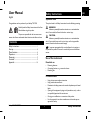
User Manual
Safety Instructions
English
Symbols used
The symbols used in the Safety Instructions have the following meanings:
Congratulations on the purchase of your Stanley TLM 220i.
Carefully read the Safety Instructions and the User
WARNING:
Indicates a potentially hazardous situation or an unintended use
which, if not avoided, will result in death or serious injury.
Manual before using this product.
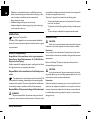
The person responsible for the instrument must
CAUTION:
Indicates a potentially hazardous situation or an unintended use
which, if not avoided, may result in minor injury and/or in appreciable
material, financial and environmental damage.
ensure that all users understand these directions and adhere to them.
Contents
)
Safety Instructions ...................................................................... 1
Start-up ........................................................................................... 4
Menu functions ............................................................................ 6
Operation ...................................................................................... 8
Measuring ....................................................................................... 9
Functions ........................................................................................ 9
Appendix ...................................................................................... 14
Important paragraphs which must be adhered to in practice as
they enable the product to be used in a technically correct and efficient
manner.
Use of the instrument
Permitted use
•
•
•
Measuring distances
Computing functions, e. g. areas and volumes
Measuring tilts
Prohibited use
•
•
•
•
•
•
Stanley TLM 220i 773938a en
1
Using the instrument without instruction
Using outside the stated limits
Deactivation of safety systems and removal of explanatory and hazard
labels
Opening of the equipment by using tools (screwdrivers, etc.), as far as
not specifically permitted for certain cases
Carrying out modification or conversion of the product
Use of accessories from other manufacturers without the express
approval of Stanley.
Safety Instructions
EN
D
F
I
E
P
NL
N
S
DK
FIN
RUS
PL
GR
H
CZ
SK
LT
EST
LV
RO
BG
EN
D
F
I
E
P
NL
N
S
DK
FIN
RUS
PL
GR
H
CZ
SK
LT
EST
LV
RO
BG
•
•
•
•
accountable for the deployment of personnel and for their training and for
the safety of the equipment when in use.
The person in charge of the instrument has the following duties:
Deliberate or irresponsible behaviour on scaffolding, when using
ladders, when measuring near machines which are running, or near
parts of machines or installations which are unprotected
Aiming directly into the sun
Deliberate dazzling of third parties; also in the dark
Inadequate safeguards at the surveying site (e.g. when measuring on
roads, construction sites, etc.)
•
•
•
Limits of use
)
To understand the safety instructions on the product and the instructions in the User Manual.
To be familiar with local safety regulations relating to accident prevention.
To inform Stanley immediately if the equipment becomes unsafe.
Hazards in use
See section “Technical Data“.
The Stanley TLM is designed for use in areas permanently habitable by
sive environments.
CAUTION:
Watch out for erroneous distance measurements if the instrument
is defective or if it has been dropped or has been misused or modified.
Areas of responsibility
Precautions:
Carry out periodic test measurements. Particularly after the instrument
humans, do not use the product in explosion hazardous areas or in aggres-
has been subject to abnormal use, and before, during and after important
Responsibilities of the manufacturer of the original equipment:
Stanley Europe, Egide Walschaertsstraat 14-16, 2800 Mechelen,
Belgium (for short Stanley).
Stanley is responsible for supplying the product, including the User Manual
measurements.
Make sure the Stanley TLM optics are kept clean and that there is no
mechanical damage to the bumpers.
and original accessories, in a completely safe condition.
CAUTION:
In using the instrument for distance measurements or for positioning moving objects (e.g. cranes, building equipment, platforms, etc.) unforeseen events may cause erroneous measurements.
Responsibilities of the manufacturer of non-Stanley accessories
)
The manufacturers of non-Stanley accessories for the Stanley TLM
are responsible for developing, implementing and communicating safety
concepts for their products. They are also responsible for the effectiviness
of these safety concepts in combination with the Stanley equipment.
Precautions:
Only use this product as a measuring sensor, not as a control device. Your
system must be configured and operated in such a way, that in case of an
Responsibilities of the person in charge of the instrument:
erroneous measurement, malfunction of the device or power failure due
to installed safety measures (e.g. safety limit switch), it is assured that no
WARNING
The person responsible for the instrument must ensure that the
equipment is used in accordance with the instructions. This person is also
Safety Instructions
damage will occur.
2
Stanley TLM 220i 773938a en
WARNING:
Flat batteries must not be disposed of with household waste. Care
for the environment and take them to the collection points provided in
accordance with national or local regulations.
The product must not be disposed of with household waste.
harmful interference to radio communications.
However, there is no guarantee that interference will not occur in a
particular installation.
If this equipment does cause harmful interference to radio or television
Dispose of the product appropriately in accordance with the
reception, which can be determined by turning the equipment off and on,
national regulations in force in your country.
the user is encouraged to try to correct the interference by one or more
of the following measures:
Always prevent access to the product by unauthorised
•
•
•
personnel.
Electromagnetic Compatibility (EMC)
Reorient or relocate the receiving antenna.
Increase the separation between the equipment and receiver.
Connect the equipment into an outlet on a circuit different from that
to which the receiver is connected.
Consult the dealer or an experienced radio/TV technician for help
The term "electromagnetic compatibility" is taken to mean the capability of
•
the product to function smoothly in an environment where
without causing electromagnetic interference to other equipment.
WARNING:
Changes or modifications not expressly approved by Stanley for
compliance could void the user’s authority to operate the equipment.
Laser classification
electromagnetic radiation and electrostatic discharges are present, and
WARNING:
The Stanley TLM conforms to the most stringent requirements of
the relevant standards and regulations. Yet, the possibility of it causing
interference in other devices cannot be totally excluded.
Integrated distancemeter
The Stanley TLM produces a visible laser beam which emerges from the
CAUTION:
Never attempt to repair the product yourself. In case of damage,
contact the local dealership.
front of the instrument.
It is a Class 2 laser product in accordance with:
•
FCC statement (applic. in U.S.)
IEC60825-1 : 2007 "Radiation safety of laser products"
This equipment has been tested and found to comply with the limits for a
Laser Class 2 products:
Do not stare into the laser beam or direct it towards other people
Class B digital device, pursuant to part 15 of the FCC Rules. These limits
unnecessarily. Eye protection is normally afforded by aversion responses
are designed to provide reasonable protection against harmful interference
including the blink reflex.
in a residential installation.
WARNING:
Looking directly into the beam with optical aids (e.g. binoculars,
telescopes) can be hazardous.
This equipment generates, uses and can radiate radio frequency energy
and, if not installed and used in accordance with the instructions, may cause
Stanley TLM 220i 773938a en
3
Safety Instructions
EN
D
F
I
E
P
NL
N
S
DK
FIN
RUS
PL
GR
H
CZ
SK
LT
EST
LV
RO
BG
EN
D
F
I
E
P
NL
N
S
DK
FIN
RUS
PL
GR
H
CZ
SK
LT
EST
LV
RO
BG
Precautions:
Do not look directly into the beam with optical aids.
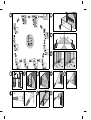
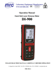
Start-up
CAUTION:
Looking into the laser beam may be hazardous to the eyes.
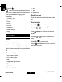
Inserting/replacing batteries
See figure {A}
Precautions:
Do not look into the laser beam. Make sure the laser is aimed above or
below eye level. (particularly with fixed installations, in machines, etc.)
Labelling
1
Remove battery compartment lid and attach handstrap.
2
Insert batteries, observing correct polarity.
3
Close the battery compartment again. Replace the batteries when the
symbol
)
)
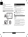
Laser Radiation
Do not stare into the beam
Laser class 2
acc. IEC 60825-1:2007
Maximum radiant power:
<1mW
Emitted wavelength:
620-690nm
Beam divergence:
0.16 x 0.6 mrad
Pulse duration:
1 x 10 -9 s
flashes permanently in the display.
Remove the batteries before any long period of non-use
to avoid the danger of corrosion.
Use alkaline batteries or rechargeable batteries only.
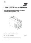
Changing the reference point (multifunctional
endpiece)
See figure {B}
The instrument can be adapted for the following measuring situations:
•
For measurements from an edge, fold out the positioning bracket until
it first locks in place. See figure {C}.
• For measurements from a corner, open the positioning bracket until
it locks in place, then push the positioning bracket lightly to the right
to fold it out fully. See figure {D}.
A built-in sensor automatically detects the orientation of the positioning
Position of the product label see last page!
Start-up
bracket and adjusts the zero point of the instrument accordingly.
4
Stanley TLM 220i 773938a en
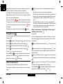
measurement field and the result bar from one another. A red triangle
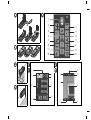
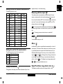
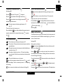
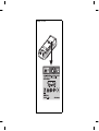
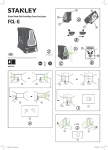
Keypad
indicates whether the selected measuring program has a detailed display
See figure {E}:
1
ON (On/measuring) button
2
Digital pointfinder button
3
Long range button
4
Plus (+) button
5
Functions button
6
Minus (-) button
7
Area / volume button
8
Menu/Equal button
9
Indirect measurement (Pythagoras) button
available.
1
Program selection with measurement instructions
2
Program selection submenu
3
Level
4
Timer
5
Measurement field
6
Result bar
7
Detailed display
8
Status bar with (Laser ON, Reference plane, Display Long range mode,
Offset, Plus / Minus, Battery status)
10 Timer button
11 Trapezium button
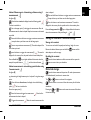
Display in "digital pointfinder" mode
12 Storage/Memory button
13 Reference button
Digital pointfinder (4x zoom)
14 Triangular area button
The device has an integral digital pointfinder, which shows the target
15 Clear/Off button
directly on the display. The displayed crosshairs allow precise measurements to be made even though the laser beam is not visible. See drawing
Display in normal mode
{F.2}
See drawing {F.1}.
The integral coloured digital pointfinder is a great help outdoors and can
The graphics screen of the measurement window is split into different
be used in every function. Longer distances and precise measurements on
areas. Top left is the brightest field, which contains the currently selected
detailed surfaces can even be accomplished in bright sunlight without any
measuring program. Just to the right appears the program submenu, which
problem.
shows the measuring programs that can be selected by pressing the same
The 4x zoom allows the image to be magnified to suit the user's requi-
key the required number of times.
rements.
The measurement field contains the individual measurements of the
Press the
measuring program with reference to a series of separate distance measu-
operate in a 1x, 2x or up to 4x zoom view.
rements. Three lines are provided for this. A horizontal line separates the
The brightness of the camera can be adjusted through 5 levels using the
Stanley TLM 220i 773938a en
5
key to activate the function. Press the
key again to
Start-up
EN
D
F
I
E
P
NL
N
S
DK
FIN
RUS
PL
GR
H
CZ
SK
LT
EST
LV
RO
BG
EN
D
F
I
E
P
NL
N
S
DK
FIN
RUS
PL
GR
H
CZ
SK
LT
EST
LV
RO
BG
key or the
key.
)
Parallax errors occur when the digital pointfinder is used on close
targets, the laser dot may appear displaced in the crosshair. In this case you
should rely on the actual laser dot for targeting the object.
Zoom step (1x, 2x, 4x)
2
Timer
3
Level (in °)
4
Crosshairs
5
Inclination angle
Offset
9
Tripod
10 Display illumination
Navigation in the menu
See drawing {F.2}
1
8
The menu allows settings to be customized for a particular user or application.
General description
Press and hold the
By pressing the
6
Distance tracking value
in the menu.
7
Image
Press the
key to enter the Setup menu.
or
keys, navigate through the main menu items
key briefly to enter the submenu of the selected main
menu item.
Menu functions
By pressing the
or
keys you can make the alterations in the
submenu.
Settings
Press and hold the
Various device settings can be made in the menu. A vertical list shows each
key to accept the settings.
entry. In this menu the selection field (cursor) remains stationary and the
Pressing the
button for longer in the menu allows you to quit the
list moves in a vertical direction. Starting from the centre of the list, the
settings function without saving.
priority of list entries starts at the top and fans out clockwise. See drawing
{G}.
The menu contains following items:
1
Units of measurement (distance)
2
Units of measurement (angle)
3
Beep
4
Digital Pointfinder image in black/white
5
Reset
6
Calibrate tilt sensor
7
Level in status field (in °)
Menu functions
6
Stanley TLM 220i 773938a en
brightest and step 1 is the darkest setting.
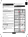
Setting the unit for distance measurements
The following units can be set:
Distance
Area
0.000 m²
Volume
0.000 m³
1.1
0.0000 m
1.2
0.000 m
0.000 m²
0.000 m³
1.3
0.00 m
0.000 m²
0.000 m³
1.4
0.00 ft
0.00 ft²
0.00 ft³
1.5
0'00'' 1/32
0.00 ft²
0.00 ft³
0'00'' 1/16
0.00 ft²
0.00 ft³
1.7
0'00''
0.00 ft²
0.00 ft³
1.8
0'00''
0.00 ft²
0.00 ft³
1.9
0.0 in
0.00 ft²
0.00 ft³
1.10
0 1/32 in
0.00 ft²
0.00 ft³
0.00 ft²
0.00 ft³
0.00 ft²
0.00 ft³
1.6
1.11
1.12
1/
8
1/
4
0 1/16in
0 1/8 in
1.13
0 1/4 in
1.14
0.000 yd
0.00 ft²
0.00 ft³
0.000 yd²
0.000 yd³
Measuring with the tripod (
requires a measurement from the actual mounting grommit versus the
front or back of the Stanley TLM. To do this select the
setting can be seen on the display
.
)
We recommend that measurements are initiated using the
key when using the device on a tripod in order to prevent loss of sharpness.
)
The settings are reset when the device is switched off.
Beep (
)
You can switch the beep on or off.
Offset (
)
An offset adds or subtracts a specified value automatically to or from all
measurements. This function allows tolerances to be taken into account
(e.g. unfinished dimensions compared with finished dimensions). If you
The following units can be set for tilt measurements:
Units for tilt
2.1
+/- 0.0°
2.2
0.00%
2.3
mm/m
2.4
in/ft
selected the Offset function in the menu, you can now adjust the value
using the
or the
key. Pressing the key for longer increases the
rate of change of the values. When you reach the desired offset value,
confirm it with the
or
key. The display shows the appropriate symbol
for as long as the offset value is set.
Digital Pointfinder image black / white (
)
)
The display in pointfinder mode can be changed to black / white.
The brightness of the display has six levels of adjustment. Step 6 is the
Stanley TLM 220i 773938a en
symbol in this
menu item. You can switch the reference on the tripod on or off. The
Setting the unit for tilt measurements
Display illumination (
)
The reference point may be adjusted to the tripod mount if the user
7
Menu functions
EN
D
F
I
E
P
NL
N
S
DK
FIN
RUS
PL
GR
H
CZ
SK
LT
EST
LV
RO
BG
EN
D
F
I
E
P
NL
N
S
DK
FIN
RUS
PL
GR
H
CZ
SK
LT
EST
LV
RO
BG
Level in status field (
)
Operation
The Level (in °) in status field can be switched on or off.
Switching on and off
Reset - returning the instrument to the factory
settings ( )
Switches on the instrument and laser. The display shows the
The instrument has a Reset function. If you select the menu function Reset
Pressing this button for longer switches the instrument off.
and confirm, the device returns to the factory settings and stack and
The instrument switches off automatically after six minutes of
memory are deleted.
inactivity.
)
battery symbol until the next button is pressed.
All customised settings and stored values are also lost.
Calibrate the tilt sensor (
CLEAR button
)
The last action is cancelled. While making area or volume measu-
You can calibrate the tilt sensor in the device. Calibration requires two
rements, each single measurement can be deleted and remeasured in
measurements on a level surface.
series.
Select calibration mode in the menu
1
2
3
.
Carry out a first measurement
on a level surface. The device
Reference setting
confirms the measurement with
.
The default reference setting is from the rear of the instrument.
Rotate the device horizontally through 180°
Press the
Press this button to take the next measurement from the front edge
.
. A special beep sounds whenever the reference setting is changed.
key and confirm that the device was rotated through
After a measurement the reference returns automatically to the default
180°.
4
Press the
setting (rear reference). See figure {H}.
key and take the second measurement. The device
confirms the measurement with
Press this button for longer the front reference is set permanently.
.
Press this button, the rear reference is set again.
The tilt sensor is calibrated.
Operation
8
Stanley TLM 220i 773938a en
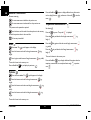
Measuring
)
Single distance measurement
Functions
Press to activate the laser. Press again to trigger the distance measu-
If the laser is in continuous operation mode, the device
switches off automatically after 15 minutes.
Overview of the program icons
rement.
The result is displayed immediately.
Measuring program
This function allows the user to measure the minimum or maximum
distance from a fixed measuring point. It can also be used as determine
spacings. See figure {I}.
Volume measurement
It is commonly used to measure room diagonals (maximum values) or hori-
Trapezoid measurement
1 (using three distances)
Trapezoid measurement
2 (using two distances
and one angle)
Pythagorean calculation
1
Pythagorean calculation
2
Pythagorean calculation
3
Inclination measurement
zontal distances (minimum values).
Press and hold down this button until you hear a beep. Then slowly
sweep the laser back and forth and up and down over the desired target
point - (e.g. into the corner of a room).
Press to stop continuous measurement. The values for maximum and
minimum distances are shown in the display as well as the last measured
value in the summary line.
Press and hold down the
)
key when switching on the device until the
Press the
N
S
DK
FIN
RUS
PL
GR
H
CZ
SK
LT
EST
LV
RO
BG
Direct horizontal
distance
character appears permanently in the display and a beep sounds. Every
further press of the
Measurement Detail display
1-2-3
1-2-3
Simple distance measurement
Area measurement
Minimum/maximum measurement
Laser continuous (
Icon
key releases a distance measurement.
Triangular area measurement
Staking out function
key and keep it pressed to switch the device and Laser
continuous operation off.
Stanley TLM 220i 773938a en
9
EN
D
F
I
E
P
NL
Measuring
EN
D
F
I
E
P
NL
N
S
DK
FIN
RUS
PL
GR
H
CZ
SK
LT
EST
LV
RO
BG
Press and hold the
Addition / subtraction
such as ceiling/floor area
Distance measuring.
rence
The next measurement is added to the previous one.
The next measurement is subtracted from the previous one.
, circumfe-
See drawing {J}
Press this button and the result is then always shown in the summary
line with the previous value in the second line.
The last step is cancelled.
Press the
key once. The symbol
Press the
key and take the first length measurement
is displayed.
(e.g.
height 1).
Press the
Area
symbol appears in the display.
Press the
(e.g.
Press it again to take the second length measurement
key and take the third length measurement
(e.g.
height 2).
length).
The result is shown in the summary row.
(e.g. width).
Press and hold the
The result is shown in the summary row.
key to display the perimeter
key again and take the second length measurement
(e.g. width)
Press this button to take the first length measurement
Press and hold the
, surface area of the walls
.
Trapezium measurement 1
This process can be repeated as required.
Press once. The
button to display additional room information
key to display additional information about the
trapezium measurement, for example inclination angle
.
area
, trapezium
.
Volume
Press this button twice. The
symbol appears in the display.
Press this button to take the first length measurement
(e.g.
length).
Press this button to take the second length measurement
(e.g.
width).
Press this button to take the third length measurement
(e.g.
height).
The result is shown in the summary row.
Functions
10
Stanley TLM 220i 773938a en
Trapezium measurement 2
Direct horizontal distance
See drawing {K}.
Press the
Press this button twice and the following symbol appears in the
key twice. This symbol
display
is displayed.
Press the
key and take the first length measurement
Press the
key and take the second length measurement
.
displays the result as the direct horizontal distance.
and
Press and hold the
inclination angle measurement.
)
and the indirect height
area
, the measured distance
.
See drawing {M}.
The result is shown in the summary row.
Press and hold the
key to display additional information about the
measurement, for example the inclination angle
The device measures inclination angles between + 45
and - 45°.
key to display additional information about the
trapezium measurement, for example inclination angle
.
Press this button to measure tilt and distance. The summary line
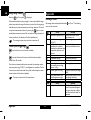
Stake out function
, trapezium
Two different distances (a and b) can be entered into the instrument and
.
can then be used to mark off defined measured lengths, e.g. in the construction of wooden frames.
Tilt measurement
)
)
)
)
)
The inclination sensor measures tilts between ± 45°.
See figure {O}.
The infocode i 160 means that the device has been set outside the
permissible limits.
Entering stake out distances:
During tilt measurement the instrument should be heldwithout a
transverse tilt (max. 10°).
appears in the display
If the device is tilted by more than ± 10° laterally, the display
shows infocode i 156 which means that the device has been tilted
too much.
suit the desired stake out distances. Holding the buttons down increases
Press this button three times and the stake out function symbol
By using
Once the desired value (a)
symbol
the
Value (b)
on the setting.
is confirmed with the
Press to measure the inclination and the distance. See figure {L}.
Pressing the
11
has been reached it can be confirmed with
button.
appears in the display. The tilt is continuously shown as ° or % depending
Stanley TLM 220i 773938a en
, you can adjust the values (first a and then b) to
the rate of change of the values.
The units of inclination are set in the menu.
Press this button once to activate the tilt sensor. The
and
.
can be entered using
and
. The defined value (b)
button.
button starts the laser measurement. The display shows
Functions
EN
D
F
I
E
P
NL
N
S
DK
FIN
RUS
PL
GR
H
CZ
SK
LT
EST
LV
RO
BG
EN
D
F
I
E
P
NL
N
S
DK
FIN
RUS
PL
GR
H
CZ
SK
LT
EST
LV
RO
BG
)
required stake out distance in the summary line between the stake out
point (first a and then b) and the instrument (rear reference).
rement:
If the Stanley TLM is then moved slowly along the stake out line the
•
•
displayed distance decreases. The instrument starts to beep at a distance
of 0.1m from the next stake out point.
The arrows in the display
indicate in which direction the Stanley
•
TLM needs to be moved in order to achieve the defined distance (either a
or b). As soon as the staking out point is reached, the symbol
appears
in the display.
The function can be stopped at any time by pressing the
button.
Make sure you adhere to the prescribed sequence of measu-
All target points must be in a horizontal or vertical plane.
The best results are achieved when the instrument is rotated about a
fixed point (e.g. with the positioning bracket fully folded out and the
instrument placed on a wall) or the Stanley TLM is mounted on a
tripod.
The minimum/maximum function can be used - see explanation in
"Measuring -> Minimum/maximum measurement". The minimum value
must be used for measurements at right angles to the target; the
maximum distance for all other measurements.
Indirect measurement - determining a distance using 2
auxilliary measurements
Triangular area
See figure {P}
The area of a triangle can be calculated by the measurement of three sides.
e.g. for measuring building heights or widths. It is helpful to use a tripod
See drawing {N}.
when measuring heights that require the measurement of two or three
Press the
key once - the triangle symbol
appears in the display.
Press the
key and measure the first side of the triangle
Press the
key and measure the second side of the triangle
Press the
key and measure the third side of the triangle
The result
measurements.
.
Press this button once, the display shows
Aim at the upper point (1) and trigger the measurement
.
zontal as possible.
key to display additional information about the
measurement, such as the angle
rements and the perimeter
Press and hold down this button to trigger continuous measurement
included by the first two measu-
, sweep the laser back and forth and up and down over the ideal target
of the triangle.
point.
Indirect measurement
Press to stop continuous measurement (2). The result is displayed in
the summary line, the partial results in the secondary line.
The instrument can calculate distances using Pythagoras’ theorem.
Press and hold the
This procedure is helpful, if the distance to measure can not be reached
key to display additional information about the
measurement of the angles of the triangle
directly.
Functions
. After
the first measurement the value is adopted. Keep the instrument as hori-
is shown in the summary row.
Press and hold the
. The laser is switched
on.
.
12
and
.
Stanley TLM 220i 773938a en
Indirect Measurement - determining a distance using 3
measurements
value is adopted.
Press and hold down this button to trigger continuous measurement
See figure {Q}
. Sweep the laser up and down over the ideal target point.
Press this button twice; the display shows the following symbol
.
Press this button to end continuous measurement. The result is
The laser is switched on.
displayed in the summary line, the partial results in the secondary lines.
Aim at the upper point (1) and trigger the measurement. After the
Press and keep pressed the
first measurement the value is adopted. Keep the instrument as horizontal
key to display additional information
about the measurement of the partial lengths
and
.
as possible
Press and hold down this button to trigger continuous measurement
Storage of constants / historical storage
, sweep the laser up and down over the ideal target point.
Storage of a constant
Press to stop continuous measurement (2). The value is adopted. Aim
You can store and recall a frequently used value e.g. height of a room.
at the lower point and
Measure the desired distance, press and hold the
press this button to trigger the measurement (3)
displayed in the summary line, the partial results in the secondary lines.
Press and hold the
Recalling the constant
key to display additional information about for
example the partial distances
and the minimum distance
,
Press this button twice to recall the constant and then press the
.
button to enter it into your calculation.
Indirect measurement - determining a partial value using
3 measurements
Historical storage
See figure {R}
Press this button once and the previous 20 results (measurements
e.g. determining the height between point 1 and point 2 using three target
or calculated results) are shown in reverse order.
points.
The
Press this button three times ; the display shows the following
symbol
button until the
device beeps to confirm storage.
. The result is
and
Press this button to use a result from the summary line for further
. The laser is switched on.
calculations.
Aim at the upper point (1).
Pressing the
Press this button and trigger the measurement
buttons can be used for navigation.
and
buttons at the same time erases all the values
in historical storage.
. After the first
measurement the value is adopted.
Triggers the measurement
Stanley TLM 220i 773938a en
. After the second measurement the
13
Functions
EN
D
F
I
E
P
NL
N
S
DK
FIN
RUS
PL
GR
H
CZ
SK
LT
EST
LV
RO
BG
EN
D
F
I
E
P
NL
N
S
DK
FIN
RUS
PL
GR
H
CZ
SK
LT
EST
LV
RO
BG
Long range Mode (
Press the
)
key. The symbol
Appendix
is displayed.
Message codes
Unfavourable conditions (strong sunlight or a very weak reflective target
All message codes are displayed with either
surface) may reduce the range of the device, in spite of this the long range
mode allows you to take measurements over longer distances. The use of
a tripod and measurement initiation by pressing the
key are recom-
mended when measurements over 30m are made over longer time periods
156
in these conditions. (For details see Technical specifications)
)
160
The settings are reset when the device is switched off.
162
Timer (self-triggering)
Press this button to set a 5-second time delay.
or
204
252
253
255
Press and hold down this button until the desired time delay is
reached (max. 60 seconds).
Once the key is released with the laser activated, the remaining seconds
until measurement (e.g. 59, 58, 57...) are displayed in a countdown. The last
256
5 seconds are counted down with a beep. After the last beep the measurement is taken and the value is displayed.
)
257
The timer can be used for all measurements.
260
Cause
Remedy
Transverse tilt greater than 10° Hold the instrument without
any transverse tilt
Main tilt direction, angle too
Measure angle up to max. ± 45°
high (> 45°)
The calibration has not been
Calibrate the device on an absoaccomplished on a leveled
lute horizontal leveled surface.
surface and the calibration value
is respecitvely within an ineligible area.
Calculation error
Repeat procedure
Temperature too high
Cool down instrument
Temperature too low
Warm up instrument
Use target plate
Receiver signal too weak,
measurement time too long,
distance > 100 m
Received signal too strong
Target too reflective (use target
plate)
Wrong measurement, backDarken target (measure in diffeground brightness too high
rent lighting conditions)
Laser beam interrupted
Repeat measurement
Error
Cause
Error Hardware error
Appendix
or "Error". The following
errors can be corrected:
14
Remedy
Switch on/off the device several
times. If the symbol still appears,
then your instrument is defective. Please call your dealer for
assistance.
Stanley TLM 220i 773938a en
Historical storage
Tripod thread (Type: 1/4-20)
Battery life,
Type AA, 2 x 1.5V
Protection against splashes and dust
Technical data
Distance measurements:
Measuring accuracy up to 10 m
(2 σ, standard deviation)
Range (use target plate from about 100 m)
Smallest unit displayed
Distance measurement
Minimum/maximum measurement, Continuous measurement
Area/volume calculation of room data
Addition / subtraction
Indirect measurement using
Pythagoras
Trapezium measurement
Tilt measurements:
Tilt sensor:
Accuracy (2 σ, standard deviation)
- to laser beam
- to the housing
Indirect measurement using tilt sensor
(direct horizontal distance)
Angle measurement using tilt sensor
(± 45°)
General:
Laser class
Laser type
Ø laser point
(at distances)
Autom. laser switch-off
Autom. instrument switch-off
Display illumination
Multifunctional endpiece
Timer (self-triggering)
Save constant value
Stanley TLM 220i 773938a en
typically: ± 1.0 mm*
0.05 m to 200 m
0.1 mm
9
Dimensions
Weight (with batteries)
Temperature range:
Storage
9
9
9
Operation
9
20 values
9
up to
5 000 measurements
IP 54, dust-proof,
splash-proof
143.5 x 55 x 30 mm
195 g
-25°C up to +70°C
(-13°F up to +158°F)
-10°C up to +50°C
(14°F up to +122°F)
* maximum deviation occurs under unfavourable conditions such as bright sunlight or
when measuring to poorly reflecting or very rough surfaces. Measuring accuracy
between 10 m and 30 m may deteriorate to approx. ± 0.025 mm/m, for distances
above 30 m to ± 0.1 mm/m. In long range mode the maximum deviation from a
distance of 30 m increases to +/- 0.15 mm/m.
9
± 0.3°
± 0.3°
Measuring conditions
Measuring range
9
The range is limited to 200 m.
9
At night or dusk and if the target is in shadow the measuring range without
target plate is increased. Use a target plate to increase the measurement
II
635 nm, < 1 mW
6 / 30 / 60 mm
(10 / 50 / 100 m)
after 3 min
after 6 min
9
9
9
9
range during daylight or if the target has poor reflection properties.
Target surfaces
Measuring errors can occur when measuring toward colourless liquids (e.g.
water) or dust free glass, Styrofoam or similar semi-permeable surfaces.
Aiming at high gloss surfaces may deflect the laser beam and lead to measurement errors.
Against non-reflective and dark surfaces the measuring time may increase.
15
Appendix
EN
D
F
I
E
P
NL
N
S
DK
FIN
RUS
PL
GR
H
CZ
SK
LT
EST
LV
RO
BG
EN
D
F
I
E
P
NL
N
S
DK
FIN
RUS
PL
GR
H
CZ
SK
LT
EST
LV
RO
BG
Care
Do not immerse the instrument in water. Wipe off dirt with a damp, soft
cloth. Do not use aggressive cleaning agents or solutions. Handle the instrument as you would a telescope or camera.
Warranty
The Stanley TLM 220i comes with a two year warranty from Stanley.
More detailed information can be found at: www.stanleyworks.com
All illustrations, descriptions and technical specifications may be subject to
change without prior notice.
Appendix
16
Stanley TLM 220i 773938a en
1
EXIT
1
2
3
3
1
2
max.
2
1
Stanley TLM 220i