1
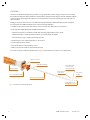
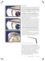
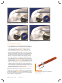
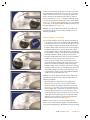
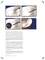
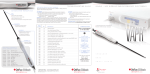
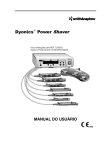
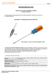
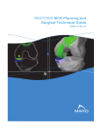
*smith&nephew
KNEE TECHNIQUE GUIDE
FAST-FIX™ 360 Meniscal Repair System
All-Inside Meniscal Repair
Charles H. Brown, Jr., MD, Nicholas Sgaglione, MD
KNEE
HIP
SHOULDER
EXTREMITIES
PRELIMINARY - NOT FOR DISTRIBUTION
All-Inside Meniscal Repair with the FAST-FIX™ 360
Meniscal Repair System
The following technique guide was prepared under the guidance of Drs. Charles H. Brown, Jr. and Nicholas Sgaglione. Created under close collaboration with
each physician, it contains a summary of medical techniques and opinions based upon their training and expertise in the field, along with their knowledge of
Smith & Nephew’s FAST-FIX 360 Meniscal Repair System. Smith & Nephew does not provide medical advice and recommends that surgeons exercise their own
professional judgment when determining a patient’s course of treatment. This guide is presented for educational purposes only.
The meniscus contributes to optimal knee joint function because of its critical role in:
Prepared in Consultation with:
• Load transmission
• Joint stability
• Articular cartilage nutrition
Charles H. Brown, Jr., MD
Medical Director
Abu Dhabi Knee & Sports Medicine Centre
Abu Dhabi, United Arab Emirates
• Shock absorption
• Lubrication
• Neuromuscular proprioception
Clinical studies have demonstrated that even partial meniscectomy can lead to
early joint chondrosis and arthrosis.1 As a result, repair of peripheral and red/white
meniscal tears is now the standard of care.
Inside-Out Repair
Nicholas Sgaglione, MD
Associate Chairman and Program Director
Department of Orthopaedic Surgery
North Shore-Long Island Jewish Medical Center
New Hyde Park, New York
Due to the ability to predictably place vertical or horizontal mattress sutures on
the femoral or tibial surfaces of the meniscus, the inside-out repair technique
is considered by many surgeons to be the “gold standard” for meniscal repair.
• Technique requires a posterior incision and dissection to avoid neurovascular
complications, thereby adding morbidity and operative time to the procedure.
• Technique requires a trained assistant to retrieve and tie the repair sutures.
Outside-In Repair
The outside-in repair technique was introduced in an attempt to eliminate the
need for a posterior incision and dissection.
• Technique offers limited access to tears in the posterior third of the meniscus.
• Limits the surgeon’s ability to perform a vertical mattress suture and place sutures
on the tibial surface of the meniscus.
All-Inside Repair
The all-inside arthroscopic suture-based technique addresses many of
the limitations of the inside-out and outside-in techniques. This technique has
gained popularity because of the following advantages:
• The repair can be safely performed without a posterior incision.
• The technique allows easy access to tears in the posterior and
middle thirds of the meniscus.
• The repair can be performed without a trained assistant.
• The technique allows vertical or horizontal mattress sutures to be inserted
on the femoral or tibial surface of the meniscus.
These advantages allow for minimally invasive meniscal repair, resulting in less
postoperative pain and morbidity for patients.2
KNEE TECHN IQUE G UID E
10600542 Rev. B
3
PRELIMINARY - NOT FOR DISTRIBUTION
Overview
The FAST-FIX™ 360 Meniscal Repair System provides a strong, reproducible, and time-saving technique for meniscal repair.
Biomechanical studies have demonstrated that a vertical mattress suture performed using the FAST-FIX 360 Meniscal Repair
System has biomechanical properties equal to that of a vertical mattress suture performed using the open and inside-out
repair techniques.
Building on the proven clinical success of the earlier FAST-FIX and ULTRA FAST-FIX Meniscal Repair Systems’ techniques,
the all new FAST-FIX 360 Meniscal Repair System offers the following advantages:
• Versatility to place horizontal or vertical mattress sutures on the femoral or tibial surfaces of the meniscus.
• Easier and faster implant deployment with added safety features:
– Implants are pushed out of the delivery needle rather than being stripped away from the needle.
– Minimizes the depth of needle penetration needed to successfully deploy the implants
– Decreased risk of injury to nearby neurovascular structures
• Smaller insertion points, minimizing disruption to the meniscus
• A built-in depth penetration limiter
• Stiffer needle shaft for enhanced delivery control
• Ability to reposition the needle for optimal suture placement
As a result, the FAST-FIX 360 meniscal Repair System (Figure 1) helps optimize the chances of a successful repair.
Auditory confirmation
Adjustable depth limiter
Needle tip available
in curved, reverse
curved, and straight
Ergonomic handle
Enhanced suture
management
360° active deployment slider
Laser-marked
needle tip
Stiffer, low-profile needle shaft
Figure 1. The FAST-FIX 360 Meniscal Repair System
4
Smaller implants and
ULTRABRAID™ 2-0 Suture
K N E E TEC HN I Q U E G UI D E
10600542 Rev. B
ked
p
PRELIMINARY - NOT FOR DISTRIBUTION
The FAST-FIX 360 Meniscal Repair System
Each FAST-FIX™ 360 Meniscal Repair System contains:
• Two 5 mm polymer integrated bio-inert PEEK anchors with a pre-tied, self-sliding knot
• 2-0, non-absorbable, UHMW polyethylene ULTRABRAID™ Suture
• The delivery needles are available in curved, straight, and reverse curved designs (Figure 2).
– The curved and reverse-curved designs allow the surgeon to rotate the needle tip away from the neurovascular structures
when penetrating the meniscus, further reducing the risk of neurovascular injury.
– The curved delivery needle is optimally shaped to allow vertical mattress sutures to be inserted on either the femoral
or tibial surfaces of the meniscus.
– The reverse-curved delivery needle is most useful for repairing tears on the tibial surface and more anterior located tears.
• The built-in, adjustable depth penetration limiter is adjustable from 10 mm to 18 mm from the tip of the needle.
• Use of the meniscal depth probe in conjunction with the adjustable depth penetration limiter (white plastic sheath) allows
controlled delivery of the implants.
Figure 2. Delivery needle designs
Procedure Setup and Portal Placement
1. The operating room setup includes a lateral thigh post or Leg Holder (REF #012310) to allow application of valgus stress
to the knee to open the medial or lateral compartments for easier access to the tear.
2.Use a surgical skin marker to outline the following surface landmarks: the patella, the medial and lateral borders of the
patellar tendon, and the medial and lateral joint lines.
3.Create the anterolateral portal at the level of the inferior pole of the patella as close as possible to the lateral border of the
patellar tendon. Perform diagnostic arthroscopy, identify the meniscal tear, and assess its suitability for repair.
4.Create the anteromedial portal under direct arthroscopic visualization. Insert an 18 gauge needle through the skin above
the medial joint line. Adjust the needle position to allow optimal insertion of the FAST-FIX 360 delivery needle. Adjust
the external starting position for the needle so that the needle can be placed perpendicular to the tear. Create the
anteromedial portal in routine fashion using a #11 blade. It is important to dilate the portal with an arthroscopic conical
tip obturator (REF# 4356) to allow for easier passage of the delivery needle into the joint.
Lateral meniscal tear:
• View the tear through the anterolateral portal and use the anteromedial portal for the delivery needle.
Medial meniscal tear:
• Use the meniscal depth probe to determine if the sutures should be inserted through the anteromedial portal or if it
is necessary to switch the scope to the anteromedial portal and insert the sutures through the anterolateral portal.
• In general, medial meniscal tears in the middle third zone are best repaired by inserting the sutures through the
anterolateral portal, allowing the sutures to be inserted perpendicular to the tear.
KNEE TECHN IQUE G UID E
10600542 Rev. B
5
PRELIMINARY - NOT FOR DISTRIBUTION
Procedure
The FAST-FIX™ 360 devices are manufactured with straight or curved
delivery needles. The delivery needles are not intended to be bent by
the user. The intentional bending of the delivery needle may make it
difficult or impossible to deliver the T1 and T2 implants. If the delivery
needle has been bent inadvertently, or if resistance is encountered
during deployment, a new delivery device may be needed.
Figure 3. Establish depth limit using the adjustable depth limiter
and depth probe.
As with all arthroscopic procedures, adequate joint distention
and visualization of the meniscus tear are essential for success.
To minimize the potential for damage to neurovascular structures,
it is strongly recommended that the surgeon use the built-in,
adjustable depth penetration limiter to control the depth of
penetration of the delivery needle.
Meniscal tear site preparation is essential for biological healing of
the tear. Meniscal rasps and/or arthroscopic shavers are used to
abrade and excoriate both sides of the tear and the perimeniscal
synovium. Once the optimal portal placement is determined and
the meniscal tear site is prepared, perform the repair as follows:
Figure 4. Use laser marks as a reference.
1. Use the meniscal depth probe to determine the desired depth
limit. Place the tip of the probe at the meniscosynovial junction
and determine the width of the meniscus at the desired entry
point for the delivery needle. In the average size knee, a depth
of 14 mm is usually adequate. Adjust the depth penetration
limiter to the desired length by pressing the depth limiter button
(Figure 3). This length can be adjusted outside or inside of the
joint. The laser marks on the tip of the needle can also be used
as a reference (Figure 4).
2.Insert the FAST-FIX 360 delivery needle into the joint through the
appropriate arthroscopic portal. Insertion is facilitated through the
use of the slotted cannula (sold separately) (Figure 5).
Figure 6. Introduce the delivery needle into the joint with the tip
down against the slotted cannula.
Figure 5. Use a slotted cannula to ease insertion.
The slotted cannula eases passage through the fat pad, and the
cannula can also be used to help position the tip of the delivery
needle at the desired location on the meniscus. Introduce the delivery
needle through the slotted cannula into the joint, ensuring that the tip
of the needle is pointing down (Figure 6). Once the needle is inside
the joint, the slotted cannula may be removed if desired.
Pearl: Hold the delivery needle at the handle and push the
slider with the thumb to deploy the implants. Do not advance the
deployment slider while introducing the delivery needle into the
joint or the implant will deploy prematurely.
6
K N E E TEC HN I Q U E G UI D E
10600542 Rev. B
PRELIMINARY - NOT FOR DISTRIBUTION
Figure 7. Insert the delivery needle into the meniscus through
the capsule.
Figure 8. Keep the delivery needle in position during deployment
of the implants.
Figure 9. Push the deployment slider all the way forward
to deploy T1.
Figure 10. Withdraw the delivery needle from the meniscus slowly
for better suture management.
Vertical Mattress Suture Repair
3. F or a vertical mattress suture repair, place the first implant (T1)
on the capsular side of the tear. Insert the FAST-FIX™ 360 delivery
needle into the capsule or into any remaining meniscal tissue
on the capsular side of the tear (Figure 7). Use the slotted
cannula to stabilize the meniscus, enhance visualization, and
minimize skiving of the delivery needle to ensure more accurate
placement of the implants. Position the tip of the slotted cannula
at the desired entry point and rotate the cannula away from the
direction of the neurovascular structures. Rotating the cannula
allows better visualization of the delivery needle tip and directs
the needle away from the neurovascular structures. Keeping the
delivery needle in position, push the deployment slider all the way
forward to deploy T1 (Figures 8 and 9). Proper deployment of the
implant is accompanied by a “clicking” sound. For better suture
management and to prevent pulling out the second implant (T2),
release the deployment slider and slowly withdraw the needle out
of the meniscus, keeping the needle inside the slotted cannula (if
desired) and within arthroscopic view (Figure 10).
Pearl: Release the slider right after deployment of T1 to allow the
“spring back” of the slider to its original position flush with the handle
to pick up the T2 implant (Figure 11). Do not slowly release or hold
the slider. If the slider does not spring back, the user may manually
return the slider to its original position.
KNEE TECHN IQUE G UID E
10600542 Rev. B
Figure 11. Make sure the trigger is flush to the handle
prior to deploying T2.
7
PRELIMINARY - NOT FOR DISTRIBUTION
Position the slotted cannula at the desired entry point on the inner
meniscal fragment (if desired). The entry point for the second (T2)
implant should be at least 5 mm from the tear site. Advance the
delivery nee dle until the depth penetration limiter contacts the
surface of the meniscus (Figure 12). Keeping the delivery needle
in position, push the deployment slider all the way forward to deploy
T2 (Figure 13). As with T1, proper deployment of T2 is accompanied
by a “clicking” sound. Slowly withdraw the delivery needle from the
joint after deployment of T2 (Figure 14).
Figure 12. Advance the delivery needle to the preset needle depth limit.
Pearl: Do not push the deployment slider until the needle is fully
penetrated through the meniscus to the preset depth limit or T2
will deploy prematurely.
Horizontal Mattress Suture Repair
Figure 13. Push the deployment slider all the way forward to deploy T2.
Figure 14. Withdraw the needle from the joint.
4. F or a horizontal mattress suture repair, place the first implant (T1)
at the posterior location. Place the delivery needle perpendicular
to the tear and a minimum of 5 mm from the tear site on the inner
meniscal fragment. Advance the delivery needle until the depth
penetration limiter contacts the surface of the meniscus. Keeping
the delivery needle in position, push the deployment slider all
the way forward to deploy T1. Proper deployment of the implant is
accompanied by a “clicking” sound. Release the deployment slider
and slowly withdraw the delivery needle out of the meniscus,
keeping the needle within arthroscopic view. Position the delivery
needle more anteriorly along the meniscal tear site for the
insertion of the second limb of the horizontal mattress suture.
In general, maintain a minimum width of 8 mm between the two
insertion points. Advance the delivery needle until the depth
penetration limiter contacts the surface of the meniscus. Keeping
the delivery needle in position, push the deployment slider all the
way forward to deploy T2. As with T1, proper deployment of T2 is
accompanied by a “clicking” sound. Slowly withdraw the delivery
needle from the joint after deployment of T2.
Pearl: Do not push the deployment slider until the needle is fully
penetrated through the meniscus to the preset depth limit or T2
will deploy prematurely.
Figure 15. Pull the free end of the suture.
emove the delivery needle from the knee, pulling the free
5. R
end of the suture out of the joint. The free end of the suture
is pulled to advance the sliding knot and reduce the meniscal
tear (Figure 15). It is normal to encounter firm resistance as the
knot is snugged down. It is important to pull the free end of the
suture directly perpendicular to the tear site. Wrap the suture
around several fingers and use the tibia as a fulcrum to provide
a controlled method of tightening the knot. Slowly and steadily
apply tension to the suture. In most cases, this steady pulling
of the suture will cinch the knot down (Figure 16).
Pearl: If too much resistance is encountered while advancing
the knot, use the Smith & Nephew Straight or Curved Knot Pusher/
Suture Cutter (sold separately) to help facilitate removing suture laxity.
Figure 16. Apply tension to the suture to cinch the knot down.
8
K N E E TEC HN I Q U E G UI D E
10600542 Rev. B
PRELIMINARY - NOT FOR DISTRIBUTION
Figure 17. Slide the knot pusher/suture cutter to the knot.
Figure 18. Push the knot pusher/suture cutter tip against the knot
to recess the knot.
Figure 19. Push the trigger to cut the suture.
Figure 20. Completed vertical mattress stitch.
6. T o further tighten the knot and further compress the tear site,
thread the free end of the suture through the knot pusher/suture
cutter. Both curved and straight knot pushers/suture cutters are
available. Use a suture funnel to facilitate threading of the suture.
7. While holding the suture taut, gently slide the knot pusher/suture
cutter to the knot (Figure 17). The knot pusher should engage the
suture in a direct line perpendicular to the repair. A manual suture
“pull”/“push” maneuver is suggested, and the knot should be
tightened until the desired amount of compression is generated at
the tear site.
8. Position the tip of the knot pusher/suture cutter against the knot
to ensure a 2–3 mm suture tail when the suture is cut. Continuing
to hold the suture taut, push the knot pusher/suture cutter tip
against the knot. In some cases it is possible to recess the knot
into the surface of the meniscus, leaving the tail of the suture
flush with the surface of the meniscus (Figure 18). Cut the suture
by pushing the trigger forward (Figures 19 and 20). Because of
the high strength of the suture, using a small arthroscopic basket
punch or scissors to cut the suture often results in the tail of the
suture being frayed.
9. P
lace sutures on the tibial side of the tear as well as the femoral
side of the tear to reduce puckering of the meniscus. The reverse
curved delivery needle is especially useful for placing sutures on
the tibial side of the tear.
KNEE TECHN IQUE G UID E
10600542 Rev. B
9
PRELIMINARY - NOT FOR DISTRIBUTION
Technique Pearls
• Choose the portal which most easily allows the delivery needle to be inserted perpendicular to the tear site.
• User-initiated bending of the device needle may result in implant non-deployment. If resistance to deploy an implant
is encountered, or if needle bending is observed during use, a new delivery device may be needed.
• Vertical mattress suture: T1 inserted into the capsular side of the tear; T2 inserted on the meniscal side of the tear.
• The pre-tied, self-sliding knot included in the FAST-FIX 360 Meniscal Repair System slides from (T1) to (T2). Therefore,
placing T1 further away than T2 facilitates sliding of the knot.
• Hold the device at the handle and push the slider with the thumb to deploy T1 and T2.
• Release slider after deployment of T1 to allow “spring back” of the slider to pick up T2.
• For better suture management and to prevent pulling out T2, release the deployment slider and slowly draw the needle
out of the meniscus while maintaining the needle tip within the arthroscopic view at all times.
• If the knot does not cinch smoothly, it usually requires a steady and more forceful pull, which is facilitated by wrapping
the suture around several fingers, like a pulley, and applying tension.
• Avoid over-cinching the knot, which can result in puckering of the meniscus or the suture cutting through the meniscus
and weakening the repair.
• Alternate divergent femoral side and tibial (tensile) side suture placement optimizes the strength of the repair and helps
achieve an anatomic repair.
• Consider the reverse-curved delivery needle for placing sutures on the tibial surface of the meniscus.
• Place the FAST-FIX 360 delivery needle either through the inferior (tibial) or superior (femoral) surface of the meniscus
for optimal strength.
• For the easiest knot sliding and avoidance of the neurovascular bundles, insert the needle perpendicular to the tear using
a contralateral approach. Use portals placed adjacent to the patella tendon to facilitate this procedure.
Postoperative Care
The FAST-FIX™ 360 Meniscal Repair System utilizes a high strength non-absorbable suture and allows the repair to
be performed with a vertical mattress suture, which has been shown to be the strongest meniscal repair technique.
As a result, the standard rehabilitation protocol used with inside-out repairs can be followed.
Additional Instruction
Prior to performing this technique, consult the Instructions for Use documentation provided with individual components –
including indications, contraindications, warnings, cautions, and instructions.
REFERENCES
1. Ak. Joy Singh, Nilachandra L, Y. Nandabir Singh, Brogen Ak. “Rehabilitation Following
Arthroscopic Partial Meniscectomy - A Neglected Issue.” IJPMR 15, April 2004: 1-6.
2. Sgaglione, Nicholas A. “Meniscus Repair: Update on New Techniques.” Techniques in
Knee Surgery 1(2) December 2002: 113-127.
10
K N E E TEC HN I Q U E G UI D E
10600542 Rev. B
* The vi
postop
surgeon
Smith &
& Neph
whatso
damag
interrup
other p
inability
Refere
1. Dat
201
ITR2. Ferg
ace
elem
Avo
3. Lars
deb
ace
fem
Art
4. Phi
D. O
for
ass
min
Sur
5. Esp
et a
imp
refi
(5):
6. Lars
deb
ace
ferm
2 ye
Me
PRELIMINARY - NOT FOR DISTRIBUTION
Ordering Information
To order the instruments used in this technique guide, call +1 800 343 5717 in the U.S. or contact an authorized
Smith & Nephew representative.
Prior to performing this technique, consult the Instructions for Use documentation provided with individual
components – including indications, contraindications, warnings, cautions, and instructions.
Reference # Description
Reference # Description
72202467
72202468
72202469
72202674
72202675
Accessories:
FAST-FIX™ 360 Straight Needle
FAST-FIX 360 Curved Needle
FAST-FIX 360 Reverse Curved Needle
Straight knot pusher/suture cutter and
slotted cannula set, single use
Curved knot pusher/suture cutter and
slotted cannula set, single use
DYONICS 25 Fluid Management System Control Unit and Accessories:
015186
014549
014550
7210977
7210450
7209950
Meniscal depth probe, reusable
45° Diamond rasp, reusable
90° Diamond rasp, reusable
Slotted cannula, reusable
Suture funnel, sterile, box of 10
Suture threaders, sterile, box of 10
7211010
DYONICS 25 Fluid management Control Unit
(Control Unit only)
7211004
DYONICS 25 Inflow Tube Set, 3 per box
7211005DYONICS 25 Inflow/Outflow Tube Set, single
suction, 3 per box
7211006DYONICS 25 Inflow/Outflow Tube Set, forked
suction, 3 per box
7211007DYONICS 25 Day Tube Set (must be used
with 7211008), 3 per box
7211008
DYONICS 25 Patient Tube Set (must be used
with 7211007), 12 per box
Refer to product catalog for DYONICS 25 Fluid Management Control
Systems (includes DYONICS 25 Control Unit, country-specific power cord,
shaver interface cable, biomed test key, user manual and quick start guide).
Patient Positioning:
Visualization:
Leg Holder (Table Clamp not included)
012310
Table Clamp
013227
012311Replacement Lateral Leg Pad (included with
REF 012310)
Faucet knob
354010
Direct-View Arthroscope, Autoclavable, 30°,
72202087
4.0 mm outer diameter, 160 mm length
Direct-View Arthroscope, Autoclavable, 70°,
72202088
4.0 mm outer diameter, 160 mm length
72201919
560P Camera Control Unit, High Definition Camera
System (Control Unit only)
Refer to product catalog for 560P Camera Control Unit Systems (includes
560P Camera Control Unit, power cord, HD-SDI cable, RG-59 10’ and
country specific manual)
560 Camera System
72200571
560H Non-autoclavable Camera Head, HD
72200561
HD1200 Autoclavable Camera System, US
72203388
Coupler, High Definition, Non-autoclavable,
72201635
19.5 mm, Black ring
Platinum Blades and Shaver Systems:
DYONICS™ INCISOR™ Plus PLATINUM 4.5 mm Blade
72202530
DYONICS SYNOVATOR™ PLATINUM 4.5 mm Blade
72203523 72200873
DYONICS POWER II Shaver System Control Unit
(Control Unit only) All units 100-240 VAC, 50/60 Hz
72200616DYONICS POWERMAX™ ELITE™ Handpiece with
blade multi-positioning, hand controls, suction
lever, 10 ft. (3 m) cord
7205399
DYONICS POWER Footswitch, low profile, on/off
Arthroscopic Cannula System:
6.0 mm High Flow Diagnostic Cannula Set,
3868
double-valve, rotatable
Set Includes
722008296.0 mm High Flow Diagnostic Cannula, doublevalve, rotatable
4356
Obturator, contical tip
CAUTION: U.S. Federal law restricts these devices to sale by or on the order
of a physician.
Endoscopy
Smith & Nephew, Inc.
150 Minuteman Road
Andover, MA 01810
USA
www.smith-nephew.com
+1 978 749 1000
+1 978 749 1108 Fax
+1 800 343 5717 U.S. Customer Service
Courtesy of Smith & Nephew, Inc., Endoscopy Division
™Trademark of Smith & Nephew. Registered U.S. Patent & Trademark Office.
©2012 Smith & Nephew, Inc. All rights reserved. 10/2012 10600542 Rev. B