1
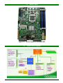
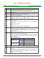
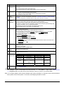
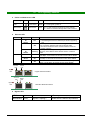
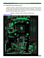
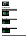
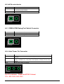
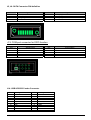
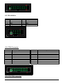
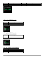
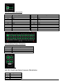
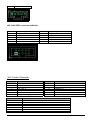
CAR-4003 Series Communication Appliance User′s Manual Revision: 1.1 Table of Contents Chapter 1 Introduction........................................................................................................... 2 1.1 About This Manual ............................................................................................................ 2 1.2 Manual Organization ......................................................................................................... 2 1.3 Technical Support Information .......................................................................................... 2 1.4 Board Layout..................................................................................................................... 3 1.5 System Block Diagram ...................................................................................................... 3 1.6 Product Specifications....................................................................................................... 4 1.7 CPU and Memory support................................................................................................. 6 1.8 LED Signaling Standard .................................................................................................... 7 Chapter 2 Getting Started ...................................................................................................... 8 2.1 Included Hardware ............................................................................................................ 8 2.2 Before You Begin .............................................................................................................. 8 2.3 Hardware Configuration Setting ........................................................................................ 9 2.4 The Chassis .................................................................................................................... 21 2.5 Open the Chassis............................................................................................................ 21 2.6 Install a Different Processor ............................................................................................ 22 2.7 Remove and Install DIMM ............................................................................................... 24 2.8 Remove and Install Compact Flash Card........................................................................ 26 2.9 Remove and Install Battery ............................................................................................. 26 2.10 Install HDD ...................................................................................................................... 27 2.11 Install Manager board ..................................................................................................... 27 2.12 Install ABN-Card link to Slot A or B ................................................................................. 28 2.13 Install ABN-Card link to Slot C ........................................................................................ 29 2.14 Ear Mount Kit Installation ................................................................................................ 29 2.15 Remove EZIO / LCD ....................................................................................................... 30 2.16 Remove Power Supply.................................................................................................... 31 2.17 Remove main board ........................................................................................................ 32 2.18 Use a Client Computer .................................................................................................... 32 Chapter 3 BIOS Setting........................................................................................................ 35 3.1 BIOS Setup Information .................................................................................................. 35 CAR-4003 Series User’s Manual 1 Chapter 1 Introduction 1.1 About This Manual This manual contains all required information for setting up and using the CAR-4003 series. CAR-4003 provides the essential platform for delivering optimal performance and functionality in the value communications appliance market segment. This manual should familiarize you with CAR-4003 operations and functions. CAR-4003 series provide up to four on-board Ethernet ports to serve communication applications like Firewall, requiring four Ethernet ports to connect external network (internet), demilitarized zone and internal network. CAR-4003 series overview: Two proprietary PCIe2.0 extension slots Compatible with Caswell’s 10G and 1G expansion modules with copper and fiber interface Support all LGA-1156 processors Quad-Core > Dual Core > Single-Core Support One PCIex4 expansion slot in rear Support IPMI module Up to 20 GbE ports Dual channel DDR3 1333/1066/800 MHz ECC 2.5GT/s DMI data rate Intel total solution 1.2 Manual Organization This manual describes how to configure your CAR-4003 system to meet various operating requirements. It is divided into three chapters, with each chapter addressing the basic concept and operation of this system. Chapter 1: Introduction. This section describes how this document is organized. It includes brief guidelines and overview to help find necessary information. Chapter 2: Hardware Configuration Setting and Installation. This chapter demonstrated the hardware assembly procedure, including detailed information. It shows the definitions and locations of Jumpers and Connectors that can be used to configure the system. Chapter 3: Operation Information. This section provides illustrations and information on the system architecture and how to optimize its performance. Any updates to this manual, would be posted on the web site: http://www.cas-well.com 1.3 Technical Support Information Users may find helpful tips or related information on Caswell’s web site: http://www.cas-well.com A direct contact to Caswell’s technical person is also available. For further support, users may also contact Caswell’s headquarter in Taipei or local distributors. Taipei Office Phone Number: +886-2-77058888 CAR-4003 Series User’s Manual 2 1.4 Figure 1-1 1.5 CAR-4003 Series User’s Manual Board Layout Board Layout of CAR-4003 M/B System Block Diagram 3 Figure 1-2 CAR-4003 Basic Block Diagram 1.6 Product Specifications Requirement Detailed Description 1 System Description CAR-4003 system series is 2 chip solution based on Intel® Clarkdale and Lynnfield ® process and Intel Ibex Peak chipset with optional configuration to meet market requirements in-between top-P4 and high-end Xeon platform segments. 2 CPU Supports LGA 1156 Server CPUs, including Clarkdale and Lynnfield, refer to Appendix-A for more detail. 3 CPU Board CAPB-4003VR with Intel® Lynnfield and Clarkdale process Board size: 194(W) x 235(D) mm 4 DIMM slots Supports ECC UDIMMs: 2 channels x 2 DIMMs, up to 8GB Supports ECC RDIMMs: 2 channels x 2 DIMMs, up to 16GB (Lynnfield only) Full range ATX PSU with total 300~350W power output will be required (depends on power-budget). Power Budget: Refer to System Power Budget Table of sec. II-4. ERD should provide related data. AC On/Off switch is required. Certification: CE, UL, 3C Operating Mode: AT with power switch. ATX with power button. Dimension: 1U single PSU – 81.5(W) x 150(D) x 40.5 (H) mm Form factor: 1U rack-mount chassis with a (rear) supporting bracket (trail) system (kit). To accommodate: M/B, EZIO-G300/EZIO-G400, PSU, one 3.5” HDDs, advanced Ethernet I/O module (ABN-458, ABN-494, ABN-522…), PCI-E card which is connected through backplane. Chassis depth: 1U w/ single PSU <18”. Two PCI-E x8 from Intel® Clarkdale or Lynnfield to on-board slot for directly connecting with proprietary PCI-E add-on modules (ABN-series). Two pairs of PCI-Ex4 signal on a single PCI-E x8 golden finger from Intel® ibex peak to the left side for connecting with ABN module card (and PCI-E x4 add-on card) thought riser PCIe configuration table 4 5 6 7 System Memory Power Supply Chassis PCI-E Architecture Mode CAR-400x-xxx1-000 CAR-400x-xxx3-000 CAR-400x-xxx5-000 CAR-400x-xxx2-000 CAR-400x-xxx4-000 CAR-400x-xxx6-000 Slot Slot A Clarkdale/ Lynnfield x4 or x8 PCIE *1 Slot B Slot C x4 or x8 PCIE *1 x4 PCIE *1or x4 PCIE *2 Slot A Slot B x4 PCIe *2 x4 PCIe *2 Slot C 1PCIe x4 or 2PCIe x4 8 Ethernet More details refer to Sec. II-1. 9 Expansion slots Form factor: 1U / 2U rack-mount chassis with a (rear) supporting bracket (trail) system (kit). To accommodate: M/B, EZIO-300/EZIO-G400, PSU, one 3.5” HDDs, advanced Ethernet I/O module (ABN-458, ABN-494, ABN-522…), PCI-E card which is connected through backplane.. CAR-4003 Series User’s Manual 4 10 Requirement Detailed Description SATA & IDE Interfaces 11 Storage 12 VGA Interface 13 Power On/Off operation 14 Front Panel 15 Rear Panel 16 Chassis Color 17 Dimension One IDE channel shall be converted from PCI bus and supports one Compact Flash Socket. The IDE interface shall support DMA mode. Two SATA Interfaces on board with lockable connectors (B6210691) HDD - System is equipped default with fixed HDD - Space for one 3.5” SATA HDD or two 2.5” SATA HDD is required. On board CF socket for CF card. Reserve a on-board VGA based on XMI Z9m or AST2050 (AST2050 for CAPB-4000VR4003) A semi-cutting hole for standard D-Sub 15-pin VGA connector on chassis. There should be an on/off switch on PSU itself or a separated on/off switch attached to PSU to turn the PSU on/off; this switch is for AT mode operation. There should be a toggle switch pin-header to allow ATX model operation. There is an “always on” item in the BIOS. System will be powered up automatically while power is resumed, if it is “on” before power failed. Customer can use OS command to shut down system power. More detailed Power on/off mode to be determined. EZIO-G300/ G400/ G500 2 NAR-7090’s module cards in normal. Maximum number is 3. One integrated connector with dual-USB connector and RJ45 connector for system console, tab-down, no LED. Pin-definition refers to Appendix B The Dual-USB connector should be optional. Hardware Reset Button Factory Default button (optional) Reserved Power button for project inquiry. LED: Signaling standard refer to Appendix D - System LED: Power, Data access. - Ethernet LED: For every Ethernet interface there should be LEDs for link status and speed of LAN-ports. - Bypass LED Reserved semi-cutting opening of D-Sub 15 connector. AC power inlet Power on/off switch Opening for system ventilation (fan). Standard Pantone Black-UC 443(W) x 446 (D) x 44 (H) 18 Environmental requirement Acoustics Temperature Relative Humidity Shock Vibration 19 Management 1. 2. Operating < 55dB 0°C to 45°C Storage --20°C to 75°C 10 to 90% RH 5 to 95% RH Transportation --- 0.5 Sine shock, 10G 0.5 sine shock, peak, 10 +/- 3 ms on one 50G peak on axis each surface. 0.25G (Peak) / 5~500 Hz, 1.5G / 5~200 Hz at 15 sec at each of 3 axis. each of 3 axis. Based on AST2050 w/ dedicated NIC Note 1: For Linux kernel 2.6 distribution add kernel option on boot loader “ all-generic-ide” For example: kernel /boot/vmlinuz-2.6.9-42.0.3.ELsmp ro root=LABEL=/ rhgb quiet all-generic-ide ==> "all-generic-ide", this option will let kernel identify the device on IDE bus, and enable DMA Note 2: For system stability, when execute software reset, system will delay 2~3 seconds; when execute hardware reset, system will cut off the power 1~2 seconds, the foregoing situation is normal. CAR-4003 Series User’s Manual 5 1.7 CPU and Memory support 1. CPU support This picture refers to the Intel authoritative information 2. Memory support CAR-4003 Series User’s Manual 6 1.8 LED Signaling Standard 3. Power and Data-access LED Lettering 4. Symbol Function Color PWR Power status Green Data Access Data Access Red Signaling Off – No power, system off. On – Power good, system on. Off – no data access through IDE or SATA channel On – data is in transition through IDE or SATA channel Ethernet LED Label ACT/LINK Color Green Or Others Indication On Off SPEED Green Or Others Flashing Yellow On Green On Off ACT/Link LED Status 1. The Ethernet port is receiving power. 2. Good linkage between the Ethernet port and its supporting hub. 1. The adapter and switch are not receiving power. 2. No connection between both ends of network cable. 3. The drivers of Ethernet have not been loaded or does not function correctly. The adapter is sending or receiving network data. The frequency of the flashes varies with the amount of network traffic. ACT/LNK LED must on then this LED show the operating at 1000 Mbps. If ACT/LINK is off and this function will be disable. ACT/LNK LED must on then this LED show the operating at 100 Mbps. If ACT/LINK is off and this function will be disable. ACT/LNK LED must on then this LED show the operating at 10 Mbps. If ACT/LINK is off and this function will be disable. Speed LED Bypass LED Copper Ethernet Interface ACT/Link Speed LED LED Bypass LED Fiber/SFP Ethernet Interface 5. Bypass LED LED Status green Bypass normal Mode/Status mode CAR-4003 Series User’s Manual red off bypass mode, triggered power off, in normal or bypass by WDT expiring mode which is defined by customer 7 Chapter 2 Getting Started This section describes how the hardware installation and system settings should be done. 2.1 Included Hardware The following hardware is included in package: CAR-4003 Communication Appliance System Board One null serial port cable 2.2 Before You Begin To prevent damage to any system board, it is important to handle it with care. The following measures are generally sufficient to protect your equipment from static electricity discharge: When handling the board, use a grounded wrist strap designed for static discharge elimination and touches a grounded metal object before removing the board from the antistatic bag. Handle the board by its edges only; do not touch its components, peripheral chips, memory modules or gold contacts. When handling processor chips or memory modules, avoid touching their pins or gold edge fingers. Restore the communications appliance system board and peripherals back into the antistatic bag when they are not in use or not installed in the chassis. Some circuitry on the system board can continue operating even though the power is switched off. Under no circumstances should the Lithium battery cell used to power the real-time clock be allowed to be shorted. The battery cell may heat up under these conditions and present a burn hazard. WARNING! 1. "CAUTION: DANGER OF EXPLOSION IF BATTERY IS INCORRECTLY REPLACED. REPLACE ONLY WITH SAME OR EQUIVALENT TYPE RECOMMENDED BY THE MANUFACTURER. DISCARD USED BATTERIES ACCORDING TO THE MANUFACTURER’S INSTRUCTIONS" 2. This guide is for technically qualified personnel who have experience installing and configuring system boards. Disconnect the system board power supply from its power source before you connect/disconnect cables or install/remove any system board components. Failure to do this can result in personnel injury or equipment damage. 3. Avoid short-circuiting the lithium battery; this can cause it to superheat and cause burns if touched. 4. Do not operate the processor without a thermal solution. Damage to the processor can occur in seconds. 5. Do not block air vents. Minimum 1/2-inch clearance required. CAR-4003 Series User’s Manual 8 2.3 Hardware Configuration Setting 2.3.1 CAR-4003 System Board Jumper In general, jumpers on CAR-4003 system board are used to select options for certain features. Some of the jumpers are configurable for system enhancement. The others are for testing purpose only and should not be altered. To select any option, cover the jumper cap over (Short) or remove (NC) it from the jumper pins according to the following instructions. Here NC stands for “Not Connected”. Jumper settings and connector functions Jumper setting CAR-4003 Series User’s Manual 9 (default setting:” ”) Reference Designator JP4 JP7 JP9 JP10 JP11 JP12 JP13 JP17 JP19 Function CMOS clear PCIE MUX selection Case open IPMI enable/disable GPIO header supply voltage PCIe lanes width selection WDT# enable/disable ICMB & IPMI Debug Port Switch Connector Auto Power On (traditional/always on) JP4:CMOS clear JP4 1-2 Short 2-3 Short Function No operation Clear CMOS JP7:PCIe MUX selection JP7 1-2 Short 2-3 Short Function Two PCIe x 4 on J10 (PCIe golden finger) One PCIe x4 on J11 (PCIe Slot) One PCIe x 4 on J10 (PCIe golden finger) JP9: Case Open Function JP9 1-2 Short 1-2 Open Function Case Open No Case open CAR-4003 Series User’s Manual 10 JP10: IPMI enable or disable JP10 1-2 Short 1-2 Open Function Disable IPMI Enable IPMI JP11:GPIO header supply voltage JP11 1-2 Short 2-3 Short Function 5V 3.3V JP12:PCIe lanes width selection JP12 1-2 Short 2-3 Short Function 2x8 4x4 CAR-4003 Series User’s Manual 11 JP13:WDT# enable/disable JP13 1-2 Short 1-2 Open Function Enable WDTO# (controlled by PCH GPIO32) Disable WDTO# JP17: ICMB & IPMI Debug Port Switch Connector JP13 1-2 Short 1-2 Open Function Switch to ICMB function. (default) Switch to IPMI Debug Port function. JP19: Auto Power On Connector JP19 1-2 Short 2-3 Short open Function Enable auto power on function. (default), generate power button pulse only one time. Enable auto power on function (always on), generate repeated power button pulses, until PSU is on, it can power on the system no matter AC loss at any period. Disable auto power on function For F5 customer: Please let JP19 2-3 short P/N : AB3-3048, AB3-3049 CAR-4003 Series User’s Manual 12 Connector Function Connector U1 J1 J2 J4 J3 J5,J6 J8,J9 J10 J11 J12 J13 J14 J15 J16 J19 J20,J21,J22 J23 J24 J42,JP2 J43 J44 J45 J46 J47 J48 JP14 JP15 JP16 Function CPU socket Memory channel A, DIMM1(black) Memory channel A, DIMM0(Blue) Memory channel B, DIMM1(black) Memory channel B, DIMM0(Blue) Remark Secondary Primary Secondary Primary SATA connector x8 PCIe connector x8 PCIe golden finger x8 PCIe connector (x4 PCIe signals is supported only) CF connector COM2 connector (for EZIO) USB/COM1 combo USB connector TPM connector CPU FAN connector SYS FAN connector (rear side) 24-pin ATX power connector +12V power connector for CPU SMbus connector for reading power status 8-bit GPIO connector PWR & HDD LED, PWR ON, REST, LDF SYS FAN connector (front side) IPMI LAN connector VGA connector Aux power connector IPMB & ICMB Connector PLD Chip Program Connector IPMI Debug Port Connector CAR-4003 Series User’s Manual 13 J5, J6: SATA Connector PIN definition Pin 1 3 5 7 Signal Name GND SATA_TX_N SATA_RX_N GND Pin 2 4 6 SATA_TX_P GND SATA_RX_P Signal Name Pin 2 4 6 8 10 DSR#2 RTS#2 CTS#2 RI#2 NC J13: COM port connector for EZIO function Pin 1 3 5 7 9 Signal Name DCD#2 RXD#2 TXD#2 DTR#2 GND Signal Name J14: USB & RS232 Combo Connector Pin 1 3 5 7 9 11 13 15 17 19 Signal Name DCD#1 RXD#1 TXD#1 DTR#1 GND GND GND USB1+ USB1VCC_USB CAR-4003 Series User’s Manual Pin 2 4 6 8 10 12 14 16 18 20 Signal Name DSR#1 RTS#1 CTS#1 RI#1 NC VCC_USB USB0USB0+ GND GND 14 J15: PIN definition Pin 1 3 5 7 9 Signal Name GND GND USB3+ USB3VCC_USB Pin 2 4 6 8 10 Signal Name VCC_USB USB2USB2+ GND GND J16: TPM Connector Pin 1 3 5 7 9 11 13 15 17 19 Signal Name PCLK_FWH LFRAME# FWH_RST# LAD3 V3P3 LAD0 NC 3VSB GND LPCPD# Pin 2 4 6 8 10 12 14 16 18 20 Signal Name GND NC VCC LAD2 LAD1 GND NC SERIRQ GND LDRQ#1 J19: CPU FAN connector CAR-4003 Series User’s Manual 15 Pin 1 3 Signal Name GND CPUFANIN0 Pin 2 4 Signal Name +12V NC J20: System FAN Connector Pin 1 2 3 Signal Name GND +12V SYSFANIN J21: System FAN Connector Pin 1 2 3 Signal Name GND +12V CPUFANIN1 J22, J45: System FAN Connector Pin 1 2 3 Signal Name GND +12V NC CAR-4003 Series User’s Manual 16 J23: ATX Power connector Pin 1 3 5 7 9 11 13 15 17 19 21 23 Signal Name V3P3 GND GND GND 5VSB +12V V3P3 GND GND GND VCC VCC Pin 2 4 6 8 10 12 14 16 18 20 22 24 Signal Name V3P3 VCC VCC ATX_PWROK +12V V3P3 -12V PS_ONGND NC VCC GND J24: Auxiliary Power Connector Pin 1 2 3 4 Signal Name GND GND VCC12_PS VCC12_PS J42, JP2: Read Power Status Connector PIN definition Pin 1 2 3 4 Signal Name SMBCLK SMBDAT NC GND CAR-4003 Series User’s Manual 17 5 VCC3 J43: 8-bit GPIO connector definition Pin 1 3 5 7 9 Signal Name LPC_GP37 LPC_GP36 LPC_GP35 LPC_GP34 GND Pin 2 4 6 8 10 Signal Name LPC_GP30 LPC_GP31 LPC_GP32 LPC_GP33 +5V or +3.3V J44: Combo Connector Pin 1 3 5 7 9 11 13 Signal Name VCC HDD_LED GND SYS_RST_N DEFAULT# 3VSB 2050_CHASSIS_ID_N Pin 1-3 2-4 5-7 6-8 9-10 11-13 12-14 Pin 2 4 6 8 10 12 14 Signal Name VCC GND OPMA_LOCAL_LOCK_N PWRBTN_N GND 3VSB 2050_FAULT_LED_N Function HDD LED Power LED Reset Button Power button Restore to default Chassis identification LED Fail LED CAR-4003 Series User’s Manual 18 J46: IPMI LAN Connector Pin 1 3 5 7 9 Signal Name 8201_RX+ 8201_TX+ VCC3P3_AUX LED0_PHYAD0 LAN_GND_EARTH1 Pin 2 4 6 8 10 Signal Name 8201_RX8201_TXVCC3P3_AUX LED1_PHYAD1 GND Pin 2 4 6 8 10 VGA_CLK GND VGA_SDA GND NC J47: VGA Connector Pin 1 3 5 7 9 Signal Name VGA_RED VGA_GREEN VGA_BLUE VGA_VSYNC VGA_HSYNC Signal Name J48: Auxiliary Power Connector for Hard Disk Pin 1 2 3 4 Signal Name +12V GND GND VCC CAR-4003 Series User’s Manual 19 JP14: IPMB & ICMB Connector Pin 1 3 5 7 Signal Name IPMB_5VSB_SMBDAT IPMB_5VSB_SMBCLK R_ICMB_485D_N R_ICMB_485D_P Pin 2 4 6 8 Signal Name GND GND GND GND JP15: PLD Chip Program Connector Pin 1 2 3 4 5 6 7 8 Signal Name VCC3P3_AUX TDO TDI NC NC TMS GND TCK JP16: IPMI Debug Port Connector Pin 1 2 3 4 Signal Name GND NC BMC_RXD2 BMC_TXD2 CAR-4003 Series User’s Manual 20 2.4 The Chassis The system is integrated in a customized 1U chassis (Fig. 2-1, Fig. 2-2). On the front panel you will find, six LAN ports, two USB ports and a COM port. CAR-4003 Fig. 2-1 Front view of the chassis Fig. 2-2 Rear view of the chassis 2.5 CAR-4003 Series User’s Manual Open the Chassis 21 1. Loosen the 6 screws of the chassis, two on each side and the rest two on the back, to remove the top lead (Fig. 2-3). Fig. 2-3 Take off screws 2. The top lead (Fig. 2-4) can be removed from the base stand (Fig. 2-5). Fig. 2-4 The top lead Fig. 2-5 The base stand 2.6 Install a Different Processor To install a CPU 1. Local the CPU socket on the motherboard CPU socket 1156 CAR-4003 Series User’s Manual 22 2. Press the load lever with your thumb (A), then move it to left (B) until it is released from the retention tab 3. Lift the load lever in the direction of the arrow to a 135° angle 4. Lift the load plate with your thumb and forefinger to a 100° angle (A), then push the PnP cap from the load plate window to remove (B) 5. Position the CPU over the socket, making sure that the gold triangle is on the bottom-left corner of the socket. The socket alignment key should fit into the CPU notch CAR-4003 Series User’s Manual 23 6. Close the load plate (A), then push the load lever (B) until it snaps into the retention tab Configure Processor Speed The system was designed to self-detect its CPU speed. So it does not require any system adjustment. 2.7 Remove and Install DIMM Follow these steps to upgrade RAM module: 1. Installs DIMM based on the Slot order Slot 4 Slot 2 Slot 1 Slot 3 CAR-4003 Series User’s Manual 24 2. Unlock a DIMM socket by pressing the retaining clips outward 3. Align a DIMM on the socket such that the notch on the DIMM matches the break on the socket 4. Firmly insert the DIMM into the socket until the retaining clips snap back in place and the DIMM is properly seated Follow these steps to remove a DIMM: 1. Simultaneously press the retaining clips outward to unlock the DIMM CAR-4003 Series User’s Manual 25 2. Remove the DIMM from the socket 2.8 Remove and Install Compact Flash Card 1. Insert the Compact Flash Card into the CF interface Compact Flash Card Insert Compact Flash Card into the CF interface 2. The completed installation of Compact Flash Card is shown as Completion of Compact Flash Card connection 2.9 CAR-4003 Series User’s Manual Remove and Install Battery 26 1. Press the metal clip back to eject the button battery 2. Replace it with a new one by pressing the battery with fingertip to restore the battery Eject the battery Restore the battery 2.10 Install HDD The system has an internal drive bay for one 3.5" SATA hard disk drive. If the HDD is not preinstalled, you can install it by yourself. Follow the steps below to install the HDD: Fix the hard disk drive on the HDD Bracket with four screws. 3.5”HDD Kit Fix the hard disk drive on the HDD Bracket with four screws. Fasten the two screws to lock Hard disk fixed plate and chassis, Connect Power cable and HDD cable to CAR-4003 system board 2.11 Install Manager board CAR-4003 Series User’s Manual 27 Install Manager board control Cable and Manager board GND Cable Manager board control Cable and Manager board GND Cable link to system board Install IPMI control Cable IPMI control Cable link to system board Manager board control Cable, IPMI control Cable and Manager board GND Cable link to chassis Install manager board finish 2.12 Install ABN-Card link to Slot A or B Install ABN-Card CAR-4003 Series User’s Manual Fix the ABN-Card on the chassis with four screws. 28 2.13 Install ABN-Card link to Slot C Install Slot C link to Riser Card Install ABN-Card link to Slot C Fix the Riser Card on the chassis with four screws. Fix the ABN-Card on the chassis with four screws. 2.14 Ear Mount Kit Installation The CAR-4003 series shipped with 2 ear mount kits. The following is the installation instruction of these ear mounts: 1. Take out the L shape ear mount kits. One ear mount fits on one side of the chassis, 2. Placing the side with four holes agonists the chassis and the side with two holes face outward. 3. Fasten five screws on each side CAR-4003 Series User’s Manual 29 Fasten the screws to the side 2.15 Remove EZIO / LCD The CAR-4003 series support EZIO modules. The following is the remove instruction of these EZIO/LCD modules: 1. Remove all cables from EZIO Fig.2-14 Remove the cable from EZIO Fig.2-15 After remove the cable from EZIO 2. Remove the screws from chassis. Fig.2-16 Remove the screws from EZIO CAR-4003 Series User’s Manual Fig.2-17 Remove screws from chassis. 30 EZIO 2.16 Remove Power Supply The following is the remove step instruction of power supply. 1. Remove all power cables from main board. 2. Remove the screws from PSU Remove all cables from board Remove all cables from board Remove the screws from PSU Remove the screws from PSU CAR-4003 Series User’s Manual 31 Complete remove power supply 2.17 Remove main board The following is the remove step instruction of main board. 1. Remove all cables and heatsink from main board. 2. Remove all screws from main board. Remove all cables and heatsink from main board Complete remove main board 2.18 Use a Client Computer Connection Using Hyper Terminal If users use a headless CAR-4003 system, which has no mouse/keyboard and VGA output connected to it, the console may be used to communicate with CAR-4003. To access CAR-4003 via the console, Hyper Terminal is one of many choices. Follow the steps below for the setup: CAR-4003 Series User’s Manual 32 Note: Terminal software may need to update for correct console output. 1. Execute HyperTerminal under C:\Program Files\Accessories\HyperTerminal 2. Enter a name to create new dial 3. For the connection settings, make it Direct to Com1. 4. Please make the port settings to Baud rate 19200, Parity None, Data bits 8, Stop bits 1 5. Turn on the power of CAR-4003 system, after following screen was shown: CAR-4003 Series User’s Manual 33 6. You can then see the boot up information of CAR-4003. 7. When message “Hit <DEL> if you want to run Setup” appear during POST, after turning on or rebooting the computer, press <Tab> key immediately to enter BIOS setup program. This is the end of this section. If the terminal did not port correctly, please check the previous steps. CAR-4003 Series User’s Manual 34 Chapter 3 BIOS Setting 3.1 BIOS Setup Information Power on the system, press the <Del> to run BIOS setup. After you press the <Delete> key, the main BIOS setup menu displays. You can access the other setup screens from the main BIOS setup menu, such as the Chipset and Power menus. The BIOS setup/utility uses a key-based navigation system called hot keys. Most of the BIOS setup utility hot keys can be used at any time during the setup navigation process. These keys include <F1>, <F10>, <Enter>, <ESC>, <Arrow> keys, and so on. Control Keys Key ↑↓Up /Down ÆÅ Left/Right +Plus/ Minus Tab Function The Up and Down <Arrow> keys allow you to select a setup item or sub-screen. The Left and Right <Arrow> keys allow you to select a setup screen. For example: Main screen, Advanced screen, Chipset screen, and so on. The Plus and Minus <Arrow> keys allow you to change the field value of a particular setup item. For example: Date and Time. The <Tab> key allows you to select setup fields. CAR-4003 Series User’s Manual 35 CAR-4003 Series User’s Manual 36 Main Menu When you first enter the Setup Utility, you will enter the Main setup screen. You can always return to the Main setup screen by selecting the Main tab. There are two Main Setup options. They are described in this section. System Date / Time Use this option to change the system time and date. Highlight System Time or System Date using the <Arrow> keys. Enter new values through the keyboard. Press the <Tab> key or the <Arrow> keys to move between fields. The date must be entered in MM/DD/YY format. The time is entered in HH:MM:SS format. ¾ Advanced BIOS Setup Select the Advanced tab from the setup screen to enter the Advanced BIOS Setup screen. You can select any of the items in the left frame of the screen, such as SuperIO Configuration, to go to the sub menu for that item. You can display an Advanced BIOS Setup option by highlighting it using the <Arrow> keys. All Advanced BIOS Setup options are described in this section. The Advanced BIOS Setup screen is shown below. The sub menus are described on the following pages. ¾ IDE Configuration Setup From the IDE Configuration screen, press <Enter> to access the sub menu. Use the up and down <Arrow> keys to select an item. The settings are described on the following pages. CAR-4003 Series User’s Manual 37 ¾ SUPER IO CONFIGURATION Super IO Configuration You can use this screen to select options for the Super I/O settings. Use the up and down <Arrow> keys to select an item. Use the <Plus> and <Minus> keys to change the value of the selected option. The settings are described on the following pages. The screen is shown below. ¾ REMOTE ACCESS CONFIGURATION Remote Access Configuration You can use this screen to select options for the Remote Access Configuration. Use the up and down <Arrow> keys to select an item. Use the <Plus> and <Minus> keys to change the value of the selected option. The settings are described on the following pages. The screen is shown below. CAR-4003 Series User’s Manual 38 Remote Access You can disable or enable the BIOS remote access feature here. Serial Port Number Select the serial port you want to use for console redirection. You can set the value for this option to either COM1 or COM2. Serial Port Mode Select the baud rate you want the serial port to use for console redirection. ¾ USB Configuration You can use this screen to select options for the USB Configuration. Use the up and down <Arrow> keys to select an item. Use the <Plus> and <Minus> keys to change the value of the selected option. The settings are described on the following pages. The screen is shown below. CAR-4003 Series User’s Manual 39 Legacy USB Support Legacy USB Support refers to the USB mouse and USB keyboard support. Normally if this option is not enabled, any attached USB mouse or USB keyboard will not become available until a USB compatible operating system is fully booted with all USB drivers loaded. When this option is enabled, any attached USB mouse or USB keyboard can control the system even when there is no USB drivers loaded on the system. Set this value to enable or disable the Legacy USB Support. The Optimal and Fail-Safe default setting is Disabled. ¾ CPU Configuration You can use this screen to select options for the CPU Configuration. Use the up and down <Arrow> keys to select an item. Use the <Plus> and <Minus> keys to change the value of the selected option. Note: The CPU Configuration setup screen varies depending on the installed processor. ¾ Boot Settings Select the Boot tab from the setup screen to enter the Boot BIOS Setup screen. CAR-4003 Series User’s Manual 40 ¾ BOOT SETTINGS CONFIGURATION SCREEN Boot Settings Configuration Use this screen to select options for the Boot Settings Configuration. Use the up and down <Arrow> keys to select an item. Use the <Plus> and <Minus> keys to change the value of the selected option. The settings are described on the following pages. The screen is shown below. Quick Boot The Optimal and Fail-Safe default setting is Disabled. Quiet Boot Set this value to allow the boot up screen options to be modified between POST messages or OEM logo. The Optimal and Fail-Safe default setting is Enabled. Add-On ROM Display Mode Set this option to display add-on ROM (read-only memory) messages. The Optimal and Fail-Safe default setting is Force BIOS. An example of this is a SCSI BIOS or VGA BIOS. Boot up Num-Lock Set this value to allow the Number Lock setting to be modified during boot up. The Optimal and Fail-Safe default setting is On. PS/2 Mouse Support Set this value to allow the PS/2 mouse support to be adjusted. The Optimal and Fail-Safe default setting is Enabled Interrupt 19 Capture Set this value to allow option ROMs such as network controllers to trap BIOS interrupt 19. CAR-4003 Series User’s Manual 41 ¾ BOOT DEVICE PRIORITY Boot Device Priority Use this screen to specify the order in which the system checks for the device to boot from. To access this screen, select Boot Device Priority on the Boot Setup screen and press <Enter>. The following screen displays: ¾ Exit Menu Select the Exit tab from the setup screen to enter the Exit BIOS Setup screen. You can display an Exit BIOS Setup option by highlighting it using the <Arrow> keys. All Exit BIOS Setup options are described in this section. The Exit BIOS Setup screen is shown below. CAR-4003 Series User’s Manual 42 Saving Changes and Exit When you have completed the system configuration changes, select this option to leave Setup and reboot the computer so the new system configuration parameters can take effect. Select Exit Saving Changes from the Exit menu and press <Enter>. Discarding Changes and Exit Select this option to quit Setup without making any permanent changes to the system configuration. Select Exit Discarding Changes from the Exit menu and press <Enter>. Discard Changes Select Discard Changes from the Exit menu and press <Enter>. Load Optimal Defaults Automatically sets all Setup options to a complete set of default settings when you select this option. Select Load Optimal Defaults from the Exit menu and press <Enter>. Load Fail-Safe Defaults Automatically sets all Setup options to a complete set of default settings when you select this option. The Fail-Safe settings are designed for maximum system stability, but not maximum performance. Select the Fail-Safe Setup options if your computer is experiencing system configuration problems. Select Load Fail-Safe Defaults from the Exit menu and press <Enter>. CAR-4003 Series User’s Manual 43