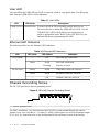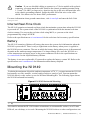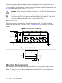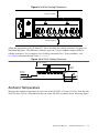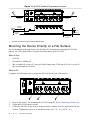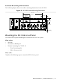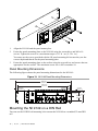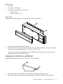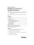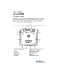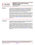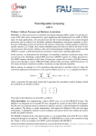
1
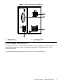
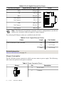
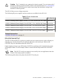
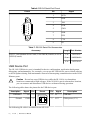
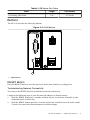
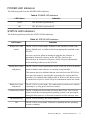
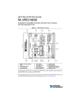
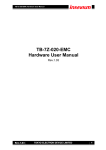
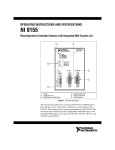
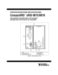
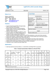
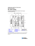
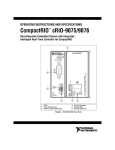
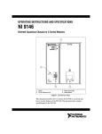
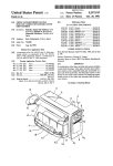
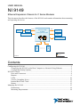
USER MANUAL
NI 9149
Ethernet Expansion Chassis for C Series Modules
This document describes the features of the NI 9149 and contains information about mounting
and operating the device.
RJ-45
Ethernet1
GigE
MAC/PHY
RGMII
Xilinx Zynq-7000
XC7Z020
All-Programmable SOC
USB 2.0 Device Port
+
512 MB
NAND Flash
256 MB
DDR3
RS-232 Serial Port
C Series
Module
C Series
Module
+
ONFI
Hardware
NI 9149
Data
Contents
Configuring the NI 9149........................................................................................................... 2
Connecting the NI 9149 to the Host Computer or Network Using Ethernet.................... 2
Configuring Startup Options............................................................................................. 3
NI 9149 Features....................................................................................................................... 4
Ports and Connectors........................................................................................................ 4
Buttons.............................................................................................................................. 9
LEDs............................................................................................................................... 10
Chassis Grounding Screw............................................................................................... 12
Internal Real-Time Clock................................................................................................13
Battery............................................................................................................................. 13
Mounting the NI 9149.............................................................................................................13
Dimensions......................................................................................................................14
Mounting Requirements..................................................................................................14
Ambient Temperature......................................................................................................15
Mounting the Device Directly on a Flat Surface............................................................ 16
Mounting the NI 9149 on a Panel................................................................................... 17
Mounting the NI 9149 on a DIN Rail............................................................................. 18
Mounting the Device on a Rack......................................................................................20
Mounting the Device on a Desktop.................................................................................20
Worldwide Support and Services............................................................................................ 20
Configuring the NI 9149
You can connect the NI 9149 to a host computer or network and configure the startup options
using the USB device port or the RJ-45 Gigabit Ethernet port 1.
Tip Refer to the getting started guide on ni.com/manuals for basic configuration
instructions and information about connecting to a host computer using the USB
device port. NI recommends using the USB device port for configuration, debug,
and maintenance.
Connecting the NI 9149 to the Host Computer or
Network Using Ethernet
Complete the following steps to connect the NI 9149 to a host computer or Ethernet network
using the RJ-45 Gigabit Ethernet port 1. NI recommends using the RJ-45 Gigabit Ethernet port
1 for communication with deployed systems.
1. Power on the host computer or Ethernet hub.
2.
Connect the RJ-45 Gigabit Ethernet port 1 on the NI 9149 to the host computer or
Ethernet hub using a standard Category 5 (CAT-5) or better shielded, twisted-pair
Ethernet cable.
Caution To prevent data loss and to maintain the integrity of your Ethernet
installation, do not use a cable longer than 100 m (328 ft).
The NI 9149 attempts to initiate a DHCP network connection the first time you connect
using Ethernet. The NI 9149 connects to the network with a link-local IP address with the
form 169.254.x.x if it is unable to initiate a DHCP connection.
Finding the NI 9149 on the Network (DHCP)
Complete the following steps to find the NI 9149 on a network using DHCP.
1. Disable secondary network interfaces on the host computer, such as a wireless access
card on a laptop.
2.
Ensure that any anti-virus and firewall software running on the host computer allows
connections to the host computer.
Note MAX uses UDP 44525. Refer to the documentation of your firewall
software for information about configuring the firewall to allow communication
through the UDP 44525.
3.
2
Launch MAX on the host computer.
|
ni.com
|
NI 9149 User Manual
4.
Expand Remote Systems in the configuration tree and locate your system.
Tip MAX lists the system under the model number followed by the serial
number, such as NI-CRIO-9149-1856AAA.
Configuring Startup Options
Complete the following steps to configure the NI 9149 startup options in MAX.
1. In MAX, expand your system under Remote Systems.
2.
Select the Startup Settings tab to configure the startup settings.
NI 9149 Startup Options
You can configure the following NI 9149 startup options.
Table 1. NI 9149 Startup Options
Startup Option
Description
Force Safe
Mode
Rebooting the NI 9149 with this setting on starts the NI 9149 without
launching LabVIEW Real-Time or any startup applications. In safe mode,
the NI 9149 launches only the services necessary for updating
configuration and installing software.
Enable Console Rebooting the NI 9149 with this setting on redirects the console output to
Out
the RS-232 serial port. You can use a serial-port terminal program to read
the IP address and firmware version of the NI 9149. Use a null-modem
cable to connect the RS-232 serial port to a computer. Make sure that the
serial-port terminal program is configured to the following settings:
•
115,200 bits per second
•
Eight data bits
•
No parity
•
One stop bit
•
No flow control
Disable RT
Startup App
Disable FPGA
Startup App
Rebooting the NI 9149 with this setting on prevents any LabVIEW
startup applications from running.
Rebooting the NI 9149 with this setting on prevents autoloading of any
FPGA application.
Note When you reset the cRIO-906x controller either
programmatically or by using the RESET button, you also reset
the FPGA. All FPGA I/O lines are tri-stated after a reset, and
will enter predefined states once loaded.
NI 9149 User Manual
|
© National Instruments
|
3
Table 1. NI 9149 Startup Options (Continued)
Startup Option
Enable Secure
Shell (SSH)
Logins
Description
Rebooting the NI 9149 with this setting on starts sshd on the NI 9149.
Starting sshd enables logins over SSH, an encrypted communication
protocol.
Note Visit ni.com/info and enter the Info Code openssh for
more information about SSH.
LabVIEW
Project Access
Rebooting the NI 9149 with this setting on enables you to add the target
to a LabVIEW project.
NI 9149 Features
The NI 9149 provides the following features.
Ports and Connectors
The NI 9149 provides the following ports and connectors.
4
|
ni.com |
NI 9149 User Manual
Figure 1. NI 9149 Ports and Connectors
1
2
3
4
1. USB Device Port
2. RS-232 Serial Port
3. RJ-45 Ethernet Port 1
4. Power Connector
RJ-45 Gigabit Ethernet Port
The NI 9149 has one tri-speed RJ-45 Gigabit Ethernet port. By default, the Ethernet port is
enabled and configured to obtain an IP address automatically. The Ethernet port can be
configured in MAX.
The following table shows the pinout for the RJ-45 Gigabit Ethernet port.
NI 9149 User Manual |
© National Instruments
|
5
Table 2. RJ-45 Gigabit Ethernet Port Pinout
Fast Ethernet Signal
Gigabit Ethernet Signal
Pin
TX+
TX_A+
1
TX-
TX_A-
2
RX+
RX_B+
3
No Connect
TX_C+
4
No Connect
TX_C-
5
RX-
RX_B-
6
No Connect
RX_D+
7
No Connect
RX_D-
8
Pinout
1
2
3
4
5
6
7
8
Note The Ethernet port performs automatic crossover configuration so you do not
need to use a crossover cable to connect to a host computer.
The following NI Ethernet cables are available for the NI 9149.
Table 3. RJ-45 Gigabit Ethernet Cables
Cables
CAT-5E Ethernet Cable, shielded
Length
Part Number
2m
151733-02
5m
151733-05
10 m
151733-10
Related Information
Ethernet LED Indicators on page 12
Power Connector
The NI 9149 has a power connector to which you can connect a power supply. The following
table shows the pinout for the power connector.
Table 4. Power Connector Pinout
Pinout
Pin
V
C
6
|
ni.com |
NI 9149 User Manual
Description
V
Power input
C
Common
Caution The C terminal is not connected to chassis ground. You can connect the C
terminal to chassis ground externally. Refer to the specifications on ni.com/manuals
for information about the power supply input range and maximum voltage from
terminal to chassis ground.
The NI 9149 has reverse-voltage protection.
The following NI power supplies and accessories are available for the NI 9149.
Table 5. Power Accessories
Accessory
Part Number
NI PS-10 Desktop Power Supply, 24 VDC, 5 A, 100-120/200-240 VAC Input 782698-01
NI PS-14 Industrial Power Supply, 24 to 28 VDC, 3.3 A, 100-240 VAC Input 783167-01
NI PS-15 Industrial Power Supply, 24 to 28 VDC, 5 A, 100/230 VAC Input
781093-01
NI PS-16 Industrial Power Supply, 24 to 28 VDC, 10 A, 115/230 VAC Input
781094-01
NI PS-17 Industrial Power Supply, 24 to 28 VDC, 20 A, 85-276 VAC Input
781095-01
Related Information
POWER LED Indicators on page 11
RS-232 Serial Port
The NI 9149 has an RS-232 serial port to which you can connect devices such as displays or
input devices. Use the Serial VIs to read from and write to the serial port. Refer to the
LabVIEW Help for information about the Serial VIs.
Find examples on how to use NI-Serial or NI-VISA to perform serial communication in the
NI Example Finder. The NI Example Finder is located on the Help menu in the LabVIEW
Help.
Note The RS-232 serial port cannot be accessed by the user application when the
Console Out startup option is enabled.
The following table shows the pinout for the RS-232 serial port.
NI 9149 User Manual |
© National Instruments
|
7
Table 6. RS-232 Serial Port Pinout
Pinout
Pin
1
6
2
7
3
8
4
9
5
Signal
1
DCD
2
RxD
3
TxD
4
DTR
5
GND
6
DSR
7
RTS
8
CTS
9
RI
Table 7. RS-232 Serial Port Accessories
Accessory
Length Part Number
RS-232, Null-Modem Serial Cable, 9-Pin DSUB (Female) to 9-Pin
DSUB (Female)
1m
182238-01
2m
182238-02
4m
182238-04
USB Device Port
The NI 9149 USB device port is intended for device configuration, application deployment,
debugging, and maintenance. For example, you can use the USB device port to install software
or driver updates during field maintenance instead of interrupting communication on the RJ-45
Ethernet ports.
Caution Do not hot-swap USB devices while the NI 9149 is in a hazardous
location or connected to high voltages. If the NI 9149 is not in a hazardous location,
you can connect and disconnect USB devices without affecting operation.
The following table shows the pinout for the USB device port.
Description
USB data+
Ground
Signal
D+
GND
Pin
Pinout
3
4
3
2
4
1
The following NI cable is available for the NI 9149.
8
|
ni.com |
NI 9149 User Manual
Pin
Signal
Description
2
D-
USB data-
1
VCC
Cable power (5 V)
Table 8. USB Device Port Cable
Cable
NI Locking USB Cable
Length
Part Number
1m
157788-01
Buttons
The NI 9149 provides the following buttons.
Figure 2. NI 9149 Buttons
1
1. RESET Button
RESET Button
Press the RESET button to reset the processor in the same manner as cycling power.
Troubleshooting Network Connectivity
You can use the RESET button to troubleshoot network connectivity.
Complete the following steps to reset the network adapters to default settings.
1. Hold the RESET button for 5 seconds, and then release it to boot the controller in safe
mode and enable Console Out.
2.
Hold the RESET button again for 5 seconds to boot the controller into safe mode, enable
Console Out, and reset network adapters to default settings.
NI 9149 User Manual |
© National Instruments
|
9
System Reset
The following figure shows the reset behavior of the NI 9149.
Figure 3. Reset Button Behavior
Press and hold
RESET button for < 5 s
Press and hold RESET button for ≥ 5 s
Run Mode
Press and hold RESET button for < 5 s
Safe Mode
• FPGA Startup App disabled
Press and hold RESET button for ≥ 5 s
Press and hold RESET button for < 5 s
Safe Mode
• Network settings reset
• FPGA Startup App disabled
Press and hold
RESET button for ≥ 5 s
LEDs
The NI 9149 provides the following LEDs.
Figure 4. NI 9149 LEDs
1
3
2
4
1. POWER LED
2. STATUS LED
10
|
ni.com
|
NI 9149 User Manual
3. USER FPGA1 LED
4. RJ-45 Ethernet LEDs
POWER LED Indicators
The following table lists the POWER LED indicators.
Table 9. POWER LED Indicators
LED Pattern
Indication
Solid
The NI 9149 is powered on.
Off
The NI 9149 is powered off.
STATUS LED Indicators
The following table describes the STATUS LED indicators.
Table 10. STATUS LED Indicators
LED Pattern
Blinks twice and
pauses
Indication
The NI 9149 is in safe mode. Software is not installed, which is the
factory default state, or software has been improperly installed on the
NI 9149.
An error can occur when an attempt to upgrade the software is
interrupted. Reinstall software on the NI 9149. Refer to the
Measurement & Automation Explorer (MAX) Help for information
about installing software on the NI 9149.
Blinks three times
and pauses
The NI 9149 is in user-directed safe mode, or the NI 9149 is in install
mode to indicate that software is currently being installed.
This pattern may also indicate that the user has forced the NI 9149 to
boot into safe mode by pressing the reset button for longer than five
seconds or by enabling safe mode in MAX. Refer to the Measurement
& Automation Explorer (MAX) Help for information about safe mode.
Blinks four times
and pauses
The NI 9149 is in safe mode. The software has crashed twice without
rebooting or cycling power between crashes.
Continuously blinks The NI 9149 has not booted into NI Linux Real-Time. The NI 9149
either booted into an unsupported operating system, was interrupted
during the boot process, or detected an unrecoverable software error.
On momentarily
Off
The NI 9149 is booting. No action required.
The NI 9149 is in run mode. Software is installed and the operating
system is running.
NI 9149 User Manual
|
© National Instruments
|
11
User LED
You can define the USER FPGA1 LED to meet the needs of your application. The following
table lists the USER FPGA1 LED indicators.
Table 11. User LEDs
LED
LED Color
Description
USER FPGA1 Green/Yellow Use the LabVIEW FPGA Module and NI-RIO Device
Drivers software to define the USER FPGA1 LED. Use the
USER FPGA1 LED to help debug your application or
retrieve application status. Refer to the LabVIEW Help for
information about programming this LED.
Ethernet LED Indicators
The following table lists the Ethernet LED indicators.
Table 12. Ethernet LED Indicators
LED
LED Color
LED Pattern
ACT/LINK
—
Off
Green
Solid
Flashing
10/100/1000
Indication
LAN link not established
LAN link established
Activity on LAN
Yellow
Solid
1,000 Mbit/s data rate selected
Green
Solid
100 Mbit/s data rate selected
—
Off
10 Mbit/s data rate selected
Chassis Grounding Screw
The NI 9149 provides a chassis grounding screw.
Figure 5. NI 9149 Chassis Grounding Screw
1
1. Chassis grounding screw
For EMC compliance, you must connect the NI 9149 to earth ground through the chassis
ground screw. Use wire that is 1.31 mm2 (16 AWG) solid copper wire with a maximum length
of 1.5 m (5 ft). Attach the wire to the earth ground of the electrode system of the facility.
12
|
ni.com |
NI 9149 User Manual
Caution If you use shielded cabling to connect to a C Series module with a plastic
connector, you must attach the cable shield to the chassis grounding terminal using
1.31 mm2 (16 AWG) or larger wire. Attach a ring lug to the wire and attach the wire
to the chassis grounding terminal. Solder the other end of the wire to the cable
shield. Use shorter wire for better EMC performance.
For more information about ground connections, visit ni.com/info and enter the Info Code
emcground.
Internal Real-Time Clock
The NI 9149 contains an internal real-time clock that maintains system time when the NI 9149
is powered off. The system clock of the NI 9149 is synchronized with the internal real-time
clock at startup. You can set the real-time clock using MAX, or you can set the clock
programmatically using LabVIEW.
Refer to the specifications on ni.com/manuals for the real-time clock accuracy specifications.
Battery
The NI 9149 contains a lithium cell battery that stores the system clock information when the
NI 9149 is powered off. There is only a slight drain on the battery when power is applied to
the NI 9149 power connector. The rate at which the battery drains when power is disconnected
depends on the ambient storage temperature. For longer battery life, store the NI 9149 at a
cooler temperature and apply power to the power connector. Refer to the specifications on
ni.com/manuals for the expected battery lifetime.
The battery is not user-replaceable. If you need to replace the battery, contact NI. Refer to the
specifications on ni.com/manuals for information about battery disposal.
Mounting the NI 9149
To obtain the maximum allowable ambient temperature of 70 °C, you must mount the NI 9149
horizontally on a flat, metallic, vertical surface such as a panel or wall. You can mount the
NI 9149 directly to the surface or use the NI Panel Mounting Kit. The following figure shows
the NI 9149 mounted horizontally.
Figure 6. NI 9149 Horizontal Mounting
1
1. Up
You can also mount the NI 9149 in other orientations, on a nonmetallic surface, on a 35-mm
DIN rail, on a desktop, or in a rack. Mounting the NI 9149 in these or other configurations can
NI 9149 User Manual |
© National Instruments
|
13
reduce the maximum allowable ambient temperature and can affect the typical accuracy of
modules in the NI 9149. For more information about typical accuracy specifications for
C Series modules and temperature deratings caused by different mounting configurations, visit
ni.com/info and enter the Info Code criotypical.
Caution Make sure that no C Series modules are in the NI 9149 before mounting
it.
Tip Before using any of these mounting methods, record the serial number from
the back of the NI 9149 so that you can identify the NI 9149 in MAX. You will be
unable to read the serial number after you mount the NI 9149.
Dimensions
The following figures show the front and side dimensions of the NI 9149. For detailed
dimensional drawings and 3D models, visit ni.com/dimensions and search for the module
number.
Figure 7. NI 9149 Front Dimensions
88.1 mm
(3.47 in.)
272.8 mm
(10.74 in.)
4.1 mm
(0.16 in.)
Figure 8. NI 9149 Side Dimensions
44.1 mm
(1.74 in.)
29.3 mm
(1.15 in.)
14.1 mm
(0.55 in.)
44.1 mm
(1.73 in.)
Mounting Requirements
Your installation must meet the following requirements for cooling and cabling clearance.
Allow 25.4 mm (1.00 in.) on the top and the bottom of the NI 9149 for air circulation, as
shown in the following figure.
14
|
ni.com
|
NI 9149 User Manual
Figure 9. NI 9149 Cooling Dimensions
25.4 mm (1.00 in.)
25.4 mm (1.00 in.)
Allow the appropriate space in front of C Series modules for cabling clearance, as shown in
the following figure. The different connector types on C Series modules require different
cabling clearances. For a complete list of cabling clearances for C Series modules, visit
ni.com/info and enter the Info Code crioconn.
Figure 10. NI 9149 Cabling Clearance
Cabling Clearance
50.8 mm (2.00 in.)
50.8 mm
(2.00 in.)
29.1 mm
(1.14 in.)
2
63.5 mm
(2.50 in.)
1
2
62.3 mm
(2.45 in.)
25.4 mm
(1.00 in.)
25.4 mm
(1.00 in.)
63.5 mm
(2.50 in.)
Ambient Temperature
Measure the ambient temperature at each side of the NI 9149, 63.5 mm (2.50 in.) from the side
and 25.4 mm (1.00 in.) forward from the rear of the NI 9149, as shown in the following figure.
NI 9149 User Manual
|
© National Instruments
|
15
Figure 11. NI 9149 Ambient Temperature Location
1
1
63.5 mm
(2.50 in.)
1
63.5 mm
(2.50 in.)
63.5 mm
(2.50 in.)
1
25.4 mm
(1.00 in.)
25.4 mm
(1.00 in.)
63.5 mm
(2.50 in.)
1. Location for measuring the ambient temperature
Mounting the Device Directly on a Flat Surface
For environments with high shock and vibration, NI recommends mounting the NI 9149
directly on a flat, rigid surface using the mounting holes in the NI 9149.
What to Use
•
•
•
NI 9149
Screwdriver, Phillips #2
M4 or number 8 screw (x2), user-provided, longer than 23.00 mm (0.91 in.) to pass all
the way through the NI 9149
What to Do
Complete the following steps to mount the NI 9149 directly on a flat surface.
1.
2.
3.
16
Prepare the surface for mounting the NI 9149 using the Surface Mounting Dimensions.
Align the NI 9149 on the surface.
Fasten the NI 9149 to the surface using the M4 or number 8 screws appropriate for the
surface. Tighten the screws to a maximum torque of 1.3 N · m (11.5 lb · in.).
|
ni.com |
NI 9149 User Manual
Surface Mounting Dimensions
The following figure shows the surface mounting dimensions for the NI 9149.
Figure 12. NI 9149 Surface Mounting Dimensions
141.7 mm
(5.58 in.)
47.2 mm
(1.86 in.)
30.8 mm
(1.21 in.)
47.0 mm
(1.85 in.)
4.1 mm
(0.16 in.)
Mounting the NI 9149 on a Panel
You can use the NI panel mounting kit to mount the NI 9149 on a panel.
What to Use
•
•
•
NI 9149
Screwdriver, Phillips #2
NI panel mounting kit, 782863-01
–
Panel mounting plate
–
M4 x 10 screws (x4)
What to Do
Complete the following steps to mount the NI 9149 on a panel.
NI 9149 User Manual |
© National Instruments
|
17
1.
Align the NI 9149 and the panel mount plate.
2.
Fasten the panel mounting plate to the NI 9149 using the screwdriver and M4 x 10
screws. Tighten the screws to a maximum torque of 1.3 N · m (11.5 lb · in.).
You must use the screws provided with the NI panel mounting kit because they are the
correct depth and thread for the panel mounting plate.
3.
Fasten the panel mounting plate to the surface using the screwdriver and screws that are
appropriate for the surface. The maximum screw size is M5 or number 10.
Panel Mounting Dimensions
The following figure shows the panel mounting dimensions for the NI 9149.
Figure 13. NI 9149 Panel Mounting Dimensions
355.6 mm
(14.00 in.)
336.5 mm
(13.25 in.)
9.5 mm
(0.38 in.)
7.2 mm
(0.29 in.)
17.6 mm
(0.69 in.)
31.7 mm
(1.25 in.)
88.1 mm
(3.47 in.)
63.5 mm
(2.50 in.)
Mounting the NI 9149 on a DIN Rail
You can use the NI DIN rail mounting kit to mount the NI 9149 on a standard 35-mm DIN
rail.
18
|
ni.com
|
NI 9149 User Manual
What to Use
•
•
•
NI 9149
Screwdriver, Phillips #2
NI DIN rail mounting kit, 779018-01
–
DIN rail clip
–
M4 × 10 screws (x2)
What to Do
Complete the following steps to mount the NI 9149 on a DIN rail.
1.
Align the NI 9149 and the DIN rail clip.
2.
Fasten the DIN rail kit to the NI 9149 using the screwdriver and M4 × 10 screws. Tighten
the screws to a maximum torque of 1.3 N · m (11.5 lb · in.).
You must use the screws provided with the NI DIN rail kit because they are the correct
depth and thread for the DIN rail clip.
Clipping the NI 9149 on a DIN Rail
Complete the following steps to clip the NI 9149 on a DIN rail.
2
1
1.
Insert one edge of the DIN rail into the deeper opening of the DIN rail clip.
2.
Press down firmly to compress the spring until the clip locks in place on the DIN rail.
NI 9149 User Manual |
© National Instruments
|
19
Caution Ensure that no C Series modules are in the NI 9149 before removing it
from the DIN rail.
Mounting the Device on a Rack
You can use the following rack mount kits to mount the NI 9149 and other DIN rail-mountable
equipment on a standard 482.6 mm (19 in.) rack.
•
NI Sliding Rack-Mounting Kit, 779102-01
•
NI Rack-Mounting Kit, 781989-01
Note You must use the NI DIN rail mounting kit, 779018-01, in addition to a rackmounting kit.
Mounting the Device on a Desktop
You can use the NI desktop mounting kit to mount the NI 9149 on a desktop.
What to Use
•
•
•
NI 9149
Screwdriver, Phillips #2
NI desktop mounting kit, 779473-01
–
Desktop mounting brackets (x2)
What to Do
Complete the following steps to mount the NI 9149 on a desktop.
1.
Align the brackets with the mounting holes on the ends of the NI 9149.
2.
Use the screwdriver to tighten the captive screws on the end of the brackets.
Worldwide Support and Services
The NI website is your complete resource for technical support. At ni.com/support, you have
access to everything from troubleshooting and application development self-help resources to
email and phone assistance from NI Application Engineers.
Visit ni.com/services for NI Factory Installation Services, repairs, extended warranty, and
other services.
Visit ni.com/register to register your NI product. Product registration facilitates technical
support and ensures that you receive important information updates from NI.
A Declaration of Conformity (DoC) is our claim of compliance with the Council of the
European Communities using the manufacturer’s declaration of conformity. This system
affords the user protection for electromagnetic compatibility (EMC) and product safety. You
20
|
ni.com
|
NI 9149 User Manual
can obtain the DoC for your product by visiting ni.com/certification. If your product supports
calibration, you can obtain the calibration certificate for your product at ni.com/calibration.
NI corporate headquarters is located at 11500 North Mopac Expressway, Austin, Texas,
78759-3504. NI also has offices located around the world. For telephone support in the United
States, create your service request at ni.com/support or dial 1 866 ASK MYNI (275 6964). For
telephone support outside the United States, visit the Worldwide Offices section of ni.com/
niglobal to access the branch office websites, which provide up-to-date contact information,
support phone numbers, email addresses, and current events.
NI 9149 User Manual
|
© National Instruments
|
21
Refer to the NI Trademarks and Logo Guidelines at ni.com/trademarks for information on NI trademarks. Other product and
company names mentioned herein are trademarks or trade names of their respective companies. For patents covering NI
products/technology, refer to the appropriate location: Help»Patents in your software, the patents.txt file on your media, or the
National Instruments Patent Notice at ni.com/patents. You can find information about end-user license agreements (EULAs)
and third-party legal notices in the readme file for your NI product. Refer to the Export Compliance Information at ni.com/
legal/export-compliance for the NI global trade compliance policy and how to obtain relevant HTS codes, ECCNs, and other
import/export data. NI MAKES NO EXPRESS OR IMPLIED WARRANTIES AS TO THE ACCURACY OF THE INFORMATION
CONTAINED HEREIN AND SHALL NOT BE LIABLE FOR ANY ERRORS. U.S. Government Customers: The data contained in
this manual was developed at private expense and is subject to the applicable limited rights and restricted data rights as set forth
in FAR 52.227-14, DFAR 252.227-7014, and DFAR 252.227-7015.
© 2015 National Instruments. All rights reserved.
375685A-01
Oct15