1
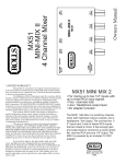
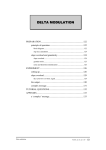
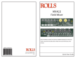
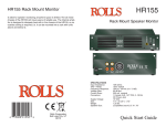
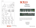
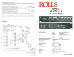
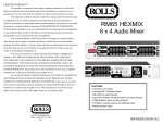
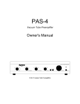
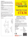
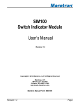
For warranty registration please visit the rolls web site at www.rolls.com.
MP222 Studio Pro Preamp
CHANNEL1 1
CHANNEL
0
OUTPUTS
MUST
BE
CH 2
INPUT
CH 3
INPUT
L
L
R
R
USED
RIGHT
-
L
CH 2
+
MUTE
OUTPUT
R
INPUT
ON - OFF
PHANTOM
POWER
CH 1
INPUT
-
ROLLS CORPORATION
SALT LAKE CITY, UTAH
10/11
80Hz
pwr
INPUT
15 VDC
+
180
10
-
LINE
OUT
MONO
INPUT
CH 1
LEVEL
CH 2
LEVEL
CH 3
LEVEL
OUTPUT
0
-30 dB
Two Channel Microphone Preamp
LEFT
INPUT
BOTH
80Hz
CH 4
LEVEL
MP222
180
10
+
0
LOW
CUT
PS12
0
-30 dB
Studio Pro Preamp
PHASE
CH 4
3.5mm
STEREO
INPUT
LEVEL
PAD
MA251
CLASS AMP
PAD
MP222
MADE IN USA
+48V
5 + 5 WATT MIX/AMP
+48V
CHANNEL
CHANNEL 22
www.rolls.com
LOW
LEVEL
PHASE CUT
MIC/
LINE
DUAL
OUTPUT
MIC/
LINE
CHANNEL 2
CH1-TIP
CH2-RING
CHANNEL 1
QUICK START
OPERATION GUIDE
INTRODUCTION
SPECIFICATIONS
Thank you for purchasing the new MP222 Studio Pro Preamp - two channel
microphone preamp. Although having many possible uses, this microphone
preamp was designed for studio applications. It has a transformer balanced mic
input section, and many variable options for getting your mic to sound just as you
want it to when recording. It is great if you are just looking for studio quality mic
processing, or any application where a high quality mic preamp is needed.
Input Impedance: mic - 600 Ohms or greater XLR
Please review this manual carefully as it contains important information regarding
the proper use of this product.
INSPECTION
1. Unpack and Inspect the MP222 package.
Your MP222 was carefully packed at the factory in a protective carton. Nonetheless, be sure to examine the unit and the carton for any signs of damage
that may have occurred during shipping. If obvious physical damage is noticed,
contact the carrier immediately to make a damage claim. We suggest saving
the shipping carton and packing materials for safely transporting the unit in the
future.
2. Please visit our web site at www.rolls.com, click on the Register Your Warranty
Here text and follow the instructions to register your MP222.
Disclaimer:
This Quick start guide assumes that the user has a basic knowledge of audio
connections. It also assumes that the user has had some experience with recording or high-end preamps.
Training and operation is the dealers responsibility. At Rolls we do not sell directly
to customers. We have factory authorized dealers and it is the dealers responsibility to gather your equipment list and recommend proper products to the
consumer. Do not call the Rolls factory and expect help with your setup. We rely
on our dealers to do such work. There is only so much that can be done over the
phone so PLEASE CONTACT YOUR LOCAL DEALER WITH QUESTIONS. If
you have purchased you item online or used, you are on your own. WE HIGHLY
RECOMMEND THAT IF YOU ARE NOT FAMILIAR WITH SUCH PRODUCTS TO
PLEASE BUY THEM FROM A REPUTABLE FACTORY AUTHORIZED DEALER
THAT OFFERS CUSTOMER SUPPORT..
1
Output Impedance:
50 Ohms
THD + Noise:
.02%
S/N Ratio:
110 dB
Frequency Response:
20 Hz - 30 kHz (+0 / -1 dB)
Max Output Level:
+14 dB
Max Input Level:
+20 dB
Max Gain:
+70 dB
Current Draw:
30 mA
Phantom Power:
+48 VDC
Input Connectors:
4 Female XLR
DC Power Jack:
(5.5 X 2.1 mm tip negative)
Output connectors:
1/8” (3.5mm) stereo out. 2 Male XLR
Size:
6.75”w x 5.125”d x 1.75” h
Weight:
1.75 lbs.
6
2
3
J2
3
J4
JAPDC
3
U6A
4069
15V REG
SW2B
3
4
2
3
1
4
6
1K
1
VPHAN
DPDT
SW4B
2
SW4A
1
R31 1K
VPHAN
C31
120PF
5
R54
10K
1
3
R60
U6C
4069
3
4
827
T2
DPDT
C30
1U
D4
LDGR
10K
R59
10K
13
C29 503
10K
1
R39
3
+V
12
VB
10
U6E
4069
Q1
2N3906
R63
1K
R11
22K
1N5242B
D23
11
C4
47U
R13
22K
4.7K
R33
1
4.7K
R9
1
+V
P3
W100K
U3A
R34
220K
VB
P1
GAIN
VB
U6F
4069
R30
10K
3
220K
U1A
27PF
4560
2
+V
R10
W100K
GAIN
C15
R8
10K
3
27PF4560
2
C3
10K
1
R14
3
SW5A
R32
47K
4
3
VB
2
VB
R7
47K
4
3
DPDT
SW2A
R58
LDGR
D3
6
5
2
P/N
2
4.7K
C32
1000U
+V
T1
1
2
5
2
4
P/N 827
2
LDGR
D2
R55
1K
+V
1K R38
DPDT
4
6
R4 1K
DPDT
SW1A
DPDT
2
SW1B
R3
4
6
1N400X
D1
22K
R57
R53
22K
4
Input Pad
6
3
1
SW5B
Input Pad
R29
6.8K DPDT
5
3
3
1
R2
6.8K DPDT
U6B
4069
6.8K
R28
R1
6.8K
PS27S ONLY
CH 2 (L)
1
J5
J8
CH 1
1
2
CH 1 (R)
XLR F PC
XLR F PC
5
6
4560
5
6
P2
U1B
+V
R41
10K
U3B
9
D20
1N5242B
1N5242B
IRLZ14L
Q2
C10
.2UF
VB
SW3A
7
2
C24
.2UF
VB
SW6A
10K 3
R43
C35
47UF
1N5242B
D21
.1U
D22
1N4148
C8
80hZ Low Cut
+V
L1
50uH
2
10K 3
R18
80hZ Low Cut
DPDT
D19
U6D
4069
8
7
DPDT
4560
L2
long board trace
VB
C23
P4
503
P100K
PHASE
R42
1K
10K
R40
+V
R17
1K
VB
PHASE
P100K
C9
503
22K
R15
R16 22K
8
J1
1
U4A
R44
4560
100
VPHAN
R62
4560
22K
C25
27PF
U2A
22K
R19
C11
27PF
C22
.1U
5
6
+V
100
R21
+V
100
R45
C7
.1U
4.7K
R48
DPDT
2
SW7B
C21
.1U
+V
R51
4.7K
OUT
DPDT
2
330
R27
3
JK3.5ST
J7
R52 330
5968 S 350 W
Murray, Utah
801-263-9053
84107
Document Number:
FXa MP222.SCH
Rev:
A
Sheet 1 of 1
OUT
XLR M PC J6
LOW
R49
330
HI SW8A
4.7K
R26
3
DPDT
XLR M PC J3
LOW
R24
330
HI SW7A
Rolls Corporation
7
3
1
3
1
R50
100 DPDT SW8B
47U
C28
7
R25
100
47U
C14
4.7K
R23
MP222 DUAL MIC PREAMP
+V
4560
U4B
R47
10K
C27
27PF
4560
U2B
10K
R22
C13
27PF
Date: 5 May 2011
Size:
Title
C36 C37
10UF 503
+V
VB
R46
10K
1
47U
VB
5
6
C26
10K
R20
1
47U
C12
6
2
1
2
XLR F PC
XLR F PC
1
2
14
7
2
2
4
4
1
1
8
3
3
5
5
4
4
4
4
8
8
2
1
2
1
5
6
5
SCHEMATIC
DESCRIPTION
FRONT PANEL
CHANNEL1 1
CHANNEL
+48V
PAD
INPUT
-30 dB
www.rolls.com
LOW
LEVEL
PHASE CUT
Studio Pro Preamp
0
CHANNEL
CHANNEL 22
10
0
180
80Hz
+48V
PAD
INPUT
-30 dB
MADE IN USA
0
MP222
LEVEL
PHASE
Two Channel Microphone Preamp
0
LOW
CUT
10
180
pwr
80Hz
FRONT PANEL DESCRIPTION
Note: Channel One descriptions are identical to Channel Two
INPUT:
Standard XLR type balanced input, pin 2 is hot, for Microphones.
-30 dB Pad:
This switch changes the level of the input. When in, it attenuates the input level
down by -30 dB.
PHANTOM POWER +48V:
Turns on the internal 48 volt power supply when using phantom powered microphones. It should be turned off when not in use. The Phantom Power switch is a
great way to turn off or mute a condenser mic. If you are recording and want to
turn your mic off this is the best way to mute it for either short or long periods of
time.
LEVEL:
Sets the output level as desired, for best signal to noise ratio it should be
set in the middle to start.
PHASE:
This is a variable setting from 0 or “in phase” to 180 degrees out of phase and
everything in between by adjusting the level of the knob.
LOW CUT:
This is a high pass filter that when depressed cuts the low end of the signal at
80Hz.
2
CONNECTION - OPERATION
REAR PANEL
CH 4
3.5mm
STEREO
MA251
CLASS AMP
BOTH
OUTPUTS
MUST
LEFT
+
-
BE
L
CH 2
INPUT
CH 3
INPUT
L
L
R
R
USED
RIGHT
-
LINE
OUT
CH 2
+
MUTE
R
CH 1
LEVEL
CH 2
LEVEL
CH 3
LEVEL
MONO
INPUT
OUTPUT
INPUT
PS12
CH 4
LEVEL
ON - OFF
PHANTOM
POWER
CH 1
INPUT
OUTPUT
5 + 5 WATT MIX/AMP
MP222
Connect microphones to the MP222 via balanced XLR cables.
INPUT
15 VDC
+
-
MIC/
LINE
DUAL
OUTPUT
MIC/
LINE
CHANNEL 2
CH1-TIP
CH2-RING
CHANNEL 1
INPUTS: 1 - 2: XLR balanced inputs for connection to any standard dynamic or
condenser microphone. The input circuitry has a very wide input range and can
accommodate almost any (mic to line) level signal if you select the proper setting
for the Mic/Line switch.
OUTPUTS: 1 - 2: XLR balanced outputs. The output circuitry has a very wide
range and can accommodate most mic XLR inputs. If you select the proper setting for the -30 dB switch on the front of the MP222.
MIC/LINE SWITCH: This is for setting up the output XLR’s for either Mic or Line
level. The mic/line switch will effect the XLR and DUAL OUTPUT levels.
IN=LINE OUT=MIC
DUAL OUTPUT: Tip-Ring-Sleeve stereo 1/8” (3.5mm) jack for connection to a
computer or other stereo type inputs. The tip of the jack is connected to channel
1 and the ring is connected to channel 2. This will make channel 1 effectively the
left output and channel 2 the right output going into a stereo application.
15 VDC JACK: For connection to the Rolls PS27s 15VDC power supply.
Make sure that you are using the proper Mic/Line switch setting. If the output
level of the MP222 seems very low or very loud it might be that you are using
the wrong mic/line switch setting. If you are using a Mic output level the mic/line
switch on the back of the MP222 is set to the Mic setting, and if you are using a
Line level output signal that the switch is in the line setting. The mic/line switch
will effect the XLR and DUAL OUTPUT levels.
IN=LINE OUT=MIC
Make sure that the input PAD switch is in the proper setting. Start with the PAD
switch in the outward position (OFF) for most Microphone applications, and
adjust it as needed. See “FRONT PANEL” section of this manual for more info
on the PAD switch. Improper PAD switch setting will make the unit seem very low
in overall volume (-30 dB to be exact). Make sure if you are using a Mic that the
PAD switch on the front of the MP222 is set to the outward position (OFF), and
if you are using a Line level input signal that the switch is in the inward -30 dB
setting (ON).
If you are using the DUAL OUTPUT connect it to the Input of your recording
device that also uses a stereo 1/8” (3.5mm) Tip-Ring-Sleeve plug. Follow the silk
screening on the back of the of the unit. The tip is connected to channel 1 and
the ring is connected to channel 2. This will make channel 1 effectively the left
output and channel 2 the right output going into a stereo application.
Connect the Rolls PS27s power supply. Once your MP222 is properly connected,
the pwr LED on the front panel will light.
If you are using condenser type microphones, apply the phantom power to the
desired channels. Test the microphone levels by speaking into the microphones
at a normal operating volume, and adjust the Mic Level controls until you achieve
desired levels. Adjust each control to the desired setting.
Adjust the PHASE and LOW CUT as desired. These can be set to any level/combination that is desired in both mic or line level. Just do what sounds best to you.
For best results, we recommend recording a couple of test runs to ensure you
have proper levels set.
3
4