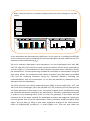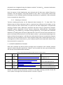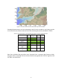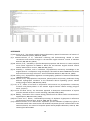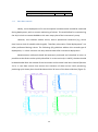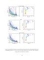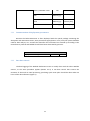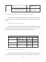
1
INTERREG IVA 2 Mers Seas Zeeen Cross-border Cooperation Programme 2007 – 2013 ISECA Deliverable 2.1: A description of the in-situ measurements, the attached protocols and the quality control. Contract: 07-027-FR-ISECA V. Martinez-Vicente, G. H. Tilstone and S.Groom Plymouth Marine Laboratory (PML) – UK Disclaimer: The document reflects the author’s views. The INTERREG IVA 2 Seas Programme Authorities are not liable for any use that may be made of the information contained therein INTERREG IVA 2 Mers Seas Zeeen Cross-border Cooperation Programme 2007 – 2013 ISECA Deliverable 2.1: Description of the in-situ measurements. Contract: 07-027-FR-ISECA V. Martinez-Vicente and G.H. Tilstone Plymouth Marine Laboratory (PML) – UK. 1 Disclaimer: The document reflects the author’s views. The INTERREG IVA 2 Seas Programme Authorities are not liable for any use that may be made of the information contained therein 2 Contents 1. SUMMARY ...................................................................................................................................... 4 2. BIOLOGICAL AND BIO-OPTICAL SAMPLING DURING ISECA............................................................ 4 2.1. 3. METHODS .................................................................................................................................... 5 2.1.1. Sampling of a time series at L4 and E1 ............................................................................... 5 2.1.2. Sampling at a transect......................................................................................................... 8 DATASETS IMPORTED IN THE WAS ................................................................................................ 8 REFERENCES .......................................................................................................................................... 10 3 Description of in-situ data in ISECA 1. SUMMARY The in-situ data in the ISECA Web Application Server (WAS), are the result of cross-border collaboration within the project. Overall, they constitute a combination of historical data (pre-ISECA) and data collected during the project life (2011-2014). In order to provide a comparable tool across the different partners, that at the same time fulfil the user requirements for Eutrophication detection; a sub-set of variables has been selected to be included in the WAS. The variables selected by the consortium for eutrophication monitoring and detection were: temperature, salinity, phytoplankton chlorophyll-a concentration, total suspended matter concentration, dissolved nutrients (NO2, NO2+NO3, NH4, SiOH4, PO4) and phytoplankton counts of species indicating of eutrophication. For the ISECA region, Phaeocystis globosa and the sum of all Phaeocystis were selected. In addition to the basic set of variables, an extended range of variables was monitored by PML following recommendations from users (D.1.2 User Requirements for the Remote sensing of Eutrophication in the 2Seas coastal waters). The first part of this report summarises the overall sampling techniques and basic data processing steps for the new data collected during ISECA by PML. Detailed methods description and quality control are described in other parts of this Deliverable (Protocols and Quality Control Guidelines). The second part of this report summarises the cross-border data that were used in the WAP. 2. BIOLOGICAL AND BIO-OPTICAL SAMPLING DURING ISECA In-situ sampling activities at L4 and E1 have two different strategies. One is long term monitoring of the vertical biological and optical properties of the water column. Another is the ad-hoc above water reflectance sampling attempting to obtain matching data with satellite overpasses. The time series approach is intended as a part of a long term effort to monitor trends in ecosystem behaviour and to test in-water algorithms. The opportunistic above water sampling is focused on obtaining a dataset useful to test adjacency effect algorithms and atmospheric correction schemes. A summary of the available datasets, the sampling methodology and processing is summarised in this report, and is based on precedent published studies [1-3]. The area of study is off the Plymouth coast (UK) (Figure 1). 4 A B C Figure 1: A) Map showing the position of the L4 and E1 stations as well as the opportunistic above water transects (dark blue line). B) Electronic in-situ optical measurements deployment cage. C) Above-water reflectance measurements in transect 2.1. METHODS 2.1.1. Sampling of a time series at L4 and E1 In situ sampling was undertaken on-board RV Plymouth Quest weekly at station L4, approximately monthly at E1 and comprised vertical profiles of hydrographic, biological and optical parameters. A summary of the samples collected since 1989 and with a focus on 2008-2012 years is given in Box 1. Water for laboratory analysis was collected near-surface in 10 L carboys and returned to the laboratory in a cool box. Samples for coloured dissolved organic matter (CDOM) determination were kept in 0.5 L dark glass bottles also transported in the cool box. Hydrography: Vertical temperature, salinity and fluorescence profiles were measured with a SeaBird SBE19 CTD coupled with a Chelsea Technology MINITracka fluorometer. Phytoplankton pigments: Phytoplankton pigments have been measured using High Performance Liquid Chromatography (HPLC) systematically at the surface at L4 since 2000. Since 2007 at L4 pigments have been also collected at depth (0, 10, 25 and 50 m).At E1 pigments have been analysed at 0, 10, 20, 30, 40 and 60m since 2002. On board, approximately 1–2 L of seawater was filtered onto a GF/F and stored in liquid nitrogen until analysis. Pigments were extracted into 2 mL methanol containing an internal standard apocarotenoate (Sigma-Aldrich Company Ltd.) using an ultrasonic probe (30 S, 50 W) following the standard PML methods [4]. Pigments were identified using retention time and spectral match using PDA [5] and pigment concentrations calculated using response factors 5 generated from calibration using a suite of pigment standards (DHIWater and Environment, Denmark). Phytoplankton primary production Phytoplankton photosynthetic parameters were calculated from photosynthesis-irradiance (P-E) curves measured using linear photosynthetrons illuminated with 50 W tungsten halogen lamps following the methods described by Tilstone et al. (2003)[6]. For each depth, 15 aliquots of 70 ml seawater within polycarbonate bottles (Nalgene) were inoculated with 5 to 10 μCi of 14C-labelled bicarbonate. Incubations were maintained at in situ temperature for a 1.5 h period, after which the samples were filtered onto GF/F under a vacuum pressure no greater than 27 kPa. The filters were then exposed to 37% fuming hydrochloric acid for ~12 h and immersed in 4 ml scintillation cocktail for 24 h, and beta-activity was counted on a TriCarb 2910 scintillation counter (PerkinElmer). Correction for quenching was performed using the external standard and the channel ratio methods. Total inorganic carbon fixation within each sample was calculated following Tilstone et al. (2003)[6] and normalized to chl a, and the curves were then fitted using the equation given by Platt et al. (1980): PB = PBs[1 − exp(−a-/PBs)]exp(−bI/PBs) (1) where a is the light-limited slope, b is the parameter representing the reduction by photoinhibition, and the maximal light photosynthetic rate (PBm) is calculated as follows: PBm = PBs[a/(a+ b)][b/(a+ b)]b/a (2) Full details of this method and analysis of the results have been recently published in Xie in press [7]. Particulate, phytoplankton, detrital and coloured dissolved organic matter absorption (CDOM) coefficients: Measurements of absorption coefficients have been made of L4 surface water since 2001. The absorption coefficients of total particulate and detrital material retained on 25 mm GF/F filters were measured before and after pigment extraction using NaClO 1% active chloride from 350 to 750 nm at a 1 nm bandwidth using a dual beam Perkin- Elmer Lambda-2 spectrophotometer retro-fitted with an integrating sphere. Concerning CDOM, replicate seawater samples were filtered through 47 mm diameter 0.2 μm Whatman Anopore membrane filters using pre-ashed glassware. The first two 0.25 L of the filtered seawater were discarded. The absorption properties of the third sample were determined immediately on the spectrophotometer and a 10 cm quartz cuvette from 350 to 750 nm, relative to a bi-distilled MilliQ reference blank. Spectral CDOM absorption (aCDOM λ , where λ refers to wavelength) was calculated from the optical density and the cuvette pathlength and baseline offset was subtracted from aCDOM. Data have been processed using published methods [8]. 6 BOX 1: Historical summary of variables sampling (Table) and recent sampling per year (Bar Charts) Measurement HPLC PABS CDOM SPM POC - CHN Chla(fluoro) Primary production FRRF Ed, Lu ac9 bb6 VSF,bb3 Above water RSR PAR Transmissometer Flow cytometry Coulter Counter Phytoplankton counts CTD SPM 1999 Part Abs 2000 2001 2002 Optical casts 2003 CDOM 2004 2005 2006 2007 2008 2009 HPLC Prim. Prod 2010 SPM 2011 2012 2013 2014 Optical casts 20 60 50 40 30 20 10 0 15 N N HPLC < 1999 10 5 0 2008 2009 2010 Year 2011 2012 2008 2009 2010 Year 2011 2012 In-situ absorption and backscattering coefficients: In-situ optics at L4 combined a WETLabs ac-9+ (to derive the particle scattering (bp) and total absorption (a)) and a WETLabs VSF-3 to measure particle backscattering (bbp). The ac-9+ measures absorption-a and attenuation-c at nine wavelengths (412, 440, 488, 510, 555, 630, 650, 676 and 715 nm) with a spectral resolution of 5nm and a measurement accuracy 0.005 m-1. The calibration has been checked using pure water calibrations and by the manufacturer. The data processing included the correction of measurements using the pure water offsets, the temperature and salinity correction (using data from the SeaBird CTD) and the scattering correction (using the “Zaneveld method”), following the recommendations from the manufacturer. bp can then be obtained by subtraction of the absorption from the attenuation. The VSF-3 measures the volume scattering function (β(θ)) at three angles (100°, 125°, and 150°) and three wavelengths (470, 530 and 660 nm). The processing of the data from the VSF meter was done in three steps. Firstly, conversion of digital counts into β(θ) done using the calibration parameters supplied by the manufacturer. Secondly, a pathlength correction in turbid or very absorbing water (c>5m-1). Given the geometry of the sensor and the characteristics of the water sampled, the pathlength correction was neglected, implying an error not greater than 5% of the measurement. Finally, calculation of bb from β(θ) at three angles. This was done by fitting a third order polynomial through all the measurements points of [2πβ(θ)sin(θ)] including θ= π, where β(θ)sin π=0. Then the area under the 7 polynomial was integrated using the Newton method. To obtain b bp, seawater backscatter (bbw) was subtracted to measured bb. Only the upcast of each deployment was selected and all data were median filtered to eliminate “salt and pepper” noise and binned to 0.5m. After a visual quality control and elimination of the individual profiles following manufacturer’s guidelines, data presented here correspond to a depth of 5m. 2.1.2. Sampling at a transect Transect sampling took place on the Plymouth Quest between 5th - 7th Sept. 2012. The objective was to collect radiometric data in a transect from offshore to the harbour, as the vessel carried out other routine tasks as a pilot test for future deployment. Unsupervised sampling of above water radiometric quantities was done using a hyperspectral Satlantic HyperSAS system composed of three sensors measuring, simultaneously, downwelling irradiance (Ed), sky radiance (Li) and water leaving radiance (Lt). This system also included a Satlantic tilt, heading and roll sensor (THR) and GPS. The three sensors were mounted on a pole on the bow of the vessel at 5 m off the water surface. L t was measured pointing to the water surface with an angle of ~ 40° from the nadir and the crew was instructed to measure away from the sun (azimuth) at 135° when possible during other routine operations [9]. A new algorithm to filter and process Rrs from radiance spectra was tested [10]. Results have been presented in a paper [11]. 3. DATASETS IMPORTED IN THE WAS Data were collected by ISECA partners through their interactions with relevant national agencies which hold data repositories. Tables 1 and 2 provide the time span and describes the sources of the different data variables. Table 1 : Data sources and reference web-sites per project partner. PML (UK) IFREMER (FR) NIOZ (NL) VITO (BE) Time Span 19882012 19982013 19902011 20032013 Link to data source http://www.westernchannelobservatory.org. uk/ http://wwz.ifremer.fr/lerpc/Activites-etMissions/Surveillance/REPHY http://live.waterbase.nl/waterbase_wns.cfm? wbwns1=en http://www.vliz.be/vmdcdata/midas/ Main person of contact Victor Martinez Vicente [email protected] Francis Gohin [email protected] Jacco Krokamp [email protected] Francisco Hernandez [email protected] Overall, 25 stations were selected for inclusion in the WAS, covering a period of over 20 years. Spatial coverage of the selected stations is shown in Figure 2 8 Figure 2 : Location of the stations selected for input into the WAS. Extended documentation on the methodology used for each variable by each data provider can be found in the relevant internet link or by contacting the person provided in Table 1. Table 2 : Data parameters and availability per partner shown by shadowed cells. PML (UK) IFREMER (FR) NIOZ (NL) VITO (BE) Temperature Salinity Chl-a SPM/Turbidity Nutrients Phaeocystis spp. Phaeocystis all Data from individual data providers were formatted into a common data format at PML, using IDL code. An example of the common data format agreed with VITO for ingestion into the WAS is provided here: 9 REFERENCES [1]S.B. Groom, et al., "The western English Channel observatory: Optical characteristics of station L4" Journal of Marine Systems, 15, 20-50, (2009). [2]V. Martinez-Vicente, et al., "Particulate scattering and backscattering related to water constituents and seasonal changes in the Western English Channel" Journal of Plankton Research, 32, 603-619, (2010). [3]G.H. Tilstone, et al., "Variability in specific-absorption properties and their use in a semi-analytical ocean colour algorithm for MERIS in North Sea and Western English Channel Coastal Waters" Remote Sens. Environ., 118, 320-338, (2012). [4]C.A. Llewellyn, J. Fishwick, and J.C. Blackford, "Phytoplankton community assemblage in the English Channel: a comparison using chlorophyll a derived from HPLC-CHEMTAX and carbon derived from microscopy cell counts" Journal of Plankton Research, 27, 103-119, (2005). [5]S.W. Jeffrey, et al., Phytoplankton pigments in oceanography: guidelines to modern methods1997: UNESCO Publishing. [6]G.H. Tilstone, et al., "Phytoplankton composition, photosynthesis and primary production during different hydrographic conditions at the Northwest Iberian upwelling system" Marine Ecology Progress Series, 252, 89-104, (2003). [7]Y. Xie, et al., "Effect of increases in temperature and nutrients on phytoplankton community structure and photosynthesis in the western English Channel" Marine Ecology Progress Series, (in press). [8]S. Tassan and G.M. Ferrari, "An alternative approach to absorption measurements of aquatic particles retained on filters" Limnol. Oceanogr., 40, 1358-1368, (1995). [9]C.D. Mobley, "Estimation of the remote-sensing reflectance from above-surface measurements" Applied Optics, 38, 7442-7455, (1999). [10]S.G.H. Simis and J. Olsson, "Unattended processing of shipborne hyperspectral reflectance measurements" Remote Sens. Environ., 135, 202-212, (2013). [11]V. Martinez-Vicente, et al. Above-water reflectance for the evaluation of adjacency effects in Earth observation data: initial results and methods comparison for near-coastal waters in the Western Channel, UK. Journal of European Optical Society Rapid Publications, 2013. 8, DOI: 10.2971/jeos.2013.13060. 10 11 INTERREG IVA 2 Mers Seas Zeeen Cross-border Cooperation Programme 2007 – 2013 ISECA Protocols for the Validation of Ocean Colour Satellite data in Case 2 European Waters. Contract: 07-027-FR-ISECA G. H. Tilstone and V. Martinez-Vicente, 2012. Plymouth Marine Laboratory (PML) – UK. Based on NASA and ESA protocols IESCA satellite validation protocols 07-027-FR-ISECA 1 INTRODUCTION TO REVAMP PROTOCOLS..................................... 5 Definition ........................................................................................................................ 6 Introduction ..................................................................................................................... 6 Instrument description .................................................................................................... 6 Analytical procedure ....................................................................................................... 7 Instrument Calibration and Quality Assurance ............................................................... 7 Methodology ................................................................................................................... 7 Sample collection and filtration .................................................................................. 7 Sample storage ............................................................................................................ 8 Measurements procedure ............................................................................................ 8 Data processing ............................................................................................................... 9 Pathlength Wavelength Correction, ............................................................................. 9 References ..................................................................................................................... 10 Backscatter coefficient, () (m-1).......................................................... 11 Introduction ................................................................................................................... 11 The Hobilabs instrument ............................................................................................... 11 Instrument description .................................................................................................. 11 Methodology and data quality control .......................................................................... 12 Deployment ............................................................................................................... 12 Windows ................................................................................................................... 12 Precautions and maintenance ........................................................................................ 13 General cleaning ....................................................................................................... 13 Pressure transducer ................................................................................................... 13 Data Processing ............................................................................................................. 13 Calibration coefficients ................................................................................................. 13 Calibration..................................................................................................................... 13 The WETLABS instrument .......................................................................................... 14 Instrument description .................................................................................................. 14 Instrument Calibration and quality assurance ............................................................... 14 Methodology and processing description ..................................................................... 14 Deployment ............................................................................................................... 14 Precautions ................................................................................................................ 14 Upkeep and Maintenance .............................................................................................. 15 Data Processing ......................................................................................................... 15 Attenuation coupling ................................................................................................. 15 References ..................................................................................................................... 15 In situ spectral Beam Attenuation coefficient - c(z,) [m-1], ................... 16 In situ spectral Absorption Coefficient - a(z,) [m-1], ............................. 16 Instrument Calibration and Quality Assurance ............................................................. 16 Mounting and Deployment of the instrument. .......................................................... 16 Field pure water calibration ...................................................................................... 16 Methodology and processing description ..................................................................... 17 Temperature and salinity corrections. ....................................................................... 17 Scattering corrections of the absorption coefficient. ................................................ 18 IESCA satellite validation protocols 07-027-FR-ISECA 2 Primary Quality Checks ............................................................................................ 18 Calibration coefficients ................................................................................................. 18 Limitations .................................................................................................................... 19 References ..................................................................................................................... 19 Coloured dissolved organic material (m-1) ............................................... 20 Definition ...................................................................................................................... 20 Instrumentation ............................................................................................................. 20 Instrument Calibration and quality assurance ............................................................... 20 Filtration and Storage.................................................................................................... 20 Measurement procedure: ............................................................................................... 21 Data Processing ............................................................................................................. 21 References. .................................................................................................................... 21 Pigments Concentration by High Performance Liquid Chromatography [mg m-3 or g l-1]......................................................................................... 23 Instrument description .................................................................................................. 23 Instrument Calibration and Quality Assurance ............................................................. 24 Determination of pigment response factors .............................................................. 24 Methodology and Processing Description. ................................................................... 24 Pigment extraction and sample preparation .............................................................. 25 Analysis program ...................................................................................................... 25 Processing description .............................................................................................. 25 Quality Assurance ..................................................................................................... 26 Sample Storage ............................................................................................................. 26 Limitations .................................................................................................................... 26 References ..................................................................................................................... 26 Surface Downwelling Spectral Irradiance, Es () (W m-2 nm-1) ............. 28 Instrument description .................................................................................................. 28 Instrument Calibration and Quality Assurance ............................................................. 29 Methodology and Processing Description. ................................................................... 29 Deployment of the instrument .................................................................................. 29 Description of processing techniques employed....................................................... 29 Primary Quality Checks ............................................................................................ 30 Primary Processing ................................................................................................... 30 Calibration coefficients ................................................................................................. 30 Limitations .................................................................................................................... 30 References ..................................................................................................................... 30 Spectral Sky Radiance - Lsky() ................................................................ 31 Spectral Direct Sun Irradiance - Esun() .................................................. 31 Instrument description CIMEL 318 Sun Photometer ................................................... 31 Instrument Calibration and Quality Assurance. ............................................................ 32 Methodology and Processing Description. ................................................................... 32 Deployment of the instrument .................................................................................. 32 Methodology for sample collection .......................................................................... 32 Primary quality checks before submission of Level 1 data ...................................... 32 Calibration coefficients ............................................................................................. 33 IESCA satellite validation protocols 07-027-FR-ISECA 3 Limitations .................................................................................................................... 33 References ..................................................................................................................... 33 Total Suspended Matter - TSM (g m-3) .................................................... 34 Instrument description .................................................................................................. 34 Definition ...................................................................................................................... 34 Instrument calibration and quality assurance ................................................................ 34 Methodology ................................................................................................................. 34 Filter preparation ....................................................................................................... 34 Filtration .................................................................................................................... 34 TSM concentration........................................................................................................ 35 Limitations .................................................................................................................... 35 References ..................................................................................................................... 35 Above-water Water Leaving Radiance, Lw (Wm-2nm-1sr-1) and Downwelling Irradiance, Es (W m-2nm-1) ................................................ 36 Instrument Description.................................................................................................. 36 QA and data processing details ..................................................................................... 36 Instrument Calibration and Quality Assurance ............................................................. 37 Methodology and Processing Description .................................................................... 37 Limitations .................................................................................................................... 37 References ..................................................................................................................... 37 Above-water MERIS reflectance, ρw () (dimensionless) – .................... 39 TriOS method............................................................................................. 39 Instrument description .................................................................................................. 39 Instrument Calibration and Quality Assurance ............................................................. 40 Methodology and Processing Description. ................................................................... 40 Deployment of the instrument .................................................................................. 40 Description of processing techniques employed....................................................... 40 Preprocessing Quality Checks .................................................................................. 41 Data Processing ......................................................................................................... 41 Postprocessing Quality Checks ................................................................................. 41 Limitations .................................................................................................................... 41 References ..................................................................................................................... 42 SIMBADA method ..................................................................................... 43 Instrument description .................................................................................................. 43 Instrument Calibration and Quality Assurance ............................................................. 44 Methodology and Processing Description. ................................................................... 44 Deployment of the instrument .................................................................................. 44 Description of processing techniques and quality checks......................................... 44 Limitations .................................................................................................................... 44 References ..................................................................................................................... 44 IESCA satellite validation protocols 07-027-FR-ISECA 4 INTRODUCTION TO ISECA PROTOCOLS In Case 1 waters Chlorophyll a (Chla) determined from Ocean Color is closely related to the absorption of light by phytoplankton pigments. Algorithms based on blue : blue – green reflectance ratios are reliable for the derivation of Chla in these waters. For Case 2 waters where high suspended particulate material (TSM) and coloured dissolved organic material (CDOM) causes a de-coupling of phytoplankton absorption and the underwater light field, accurate retrieval of Chla is far more complex and as yet remains unresolved. Optical and bio-optical protocols have been well documented for Case 1 waters for validating SeaWiFS data (Mueller & Austin 1992, Fargion & Mueller 2000), but require modification for the more complex Case 2 waters and for validating data from more recent sensors such as MODIS and MERIS. Defining the contribution of CDOM, living and non–living matter to the optical properties of the upper water column and the development of reliable and robust methodologies for Case 2 waters is fundamental for remote sensing research. The following protocols document draws on the experience of NASA’s SeaWiFS project and the EU Colors project (Coastal region long-term measurements for colour remote sensing development and validation MAS3 – CT97 – 0087; funded by the EU Marine Science and Technology Programme MAST III Startegic Marine Research) and the EU FP5 project REVAMP (Regional validation of MERIS chlorophyll products in North Sea coastal waters EVG1-CT-2001-00049; Tilstone et al. 2003). The protocols should be used in parallel with Protocols for the Validation of MERIS water products (Doerffer 2002) which documents MERIS water products, validation strategies and sampling criteria. This document builds on MERIS protocols to give more detailed guide lines for the determination of apparent and inherent optical properties of Case 2 waters of the INTERREG 2-Seas area. References Doerffer R. 2002. Protocols for the validation of MERIS water products. European Space Agency Doc. No. PO-TN-MEL-GS-0043. Fargion G.S., Mueller J.L. 2000. Ocean Optics Protocols for Satellite Ocean Colour Sensor Validation, Revision 2. NASA Goddard Space Flight Center, Greenbelt, Maryland, pp 125 – 153. Mueller J.L., Austin R.W. 1992. Ocean Optics Protocols for SeaWiFS Validation. SeaWiFS Technical Report Series. NASA Tech. Memo. 104566. Tilstone GH, Moore GF, Sorensen K, Doerffer R, Rottgers R, Ruddick KG, Pasterkamp R. (2003). Protocols for the validation of MERIS products in Case 2 waters. Proceedings from ENVISAT MAVT Conference, 20 - 24 October 2003, Frascatti, Italy. European Space Agency. http://envisat.esa.int/workshops/mavt_2003/MAVT2003_802_REVAMPprotocols3.pdf IESCA satellite validation protocols 07-027-FR-ISECA 5 In-vivo Absorption Spectra of pigmented and non pigmented Particulate Matter - apm() (m-1) Definition The light transmission of aquatic particles retained on filter. Introduction The light transmission measurement of aquatic particles retained on a filter is considered a standard method for the determination of the in vivo particle absorption. The analysis consists of measuring the fraction of a light beam passing through particles retained on a filter to derive the absorbance Apm() on the filter and is then transformed to give the equivalent absorption coefficient apm() [m-1] in suspension. Instrument description A dual beam spectrophotometer provided with a Spectralon® coated (barium sulphate degrades with seawater) integrating-sphere attachment, is ideal. In dual beam instruments, the correction for the difference in the beam efficiencies is automatically performed (Tassan and Ferrari, 1995). Single beam instruments are not recommended, as it is difficult to characterize the baseline and spectral performance of the instrument (Mitchell et al. 2000). Before sample measurements are performed, baseline and spectral noise should be well documented using air – air scans to check instrument performance, each time the spectrophotometer is switched on. Measurements are performed in the spectral range 350-800 nm with a 1nm resolution. The instrument photometric accuracy should be at least ±0.003A or ±0.08%T at 1A; ±0.002A or ±0.05%T at 0.05 A, measured with NBS 930 filters, (Perkin Elmer Lambda specifications). Systems with variable slit widths are preferred from 4 nm to below 4 nm. A NASA workshop recommended the use of Cary 100 (Mitchell et al. 2000) and EU FP5 REVAMP workshop showed that the Perkin Elmer range of spectrophotometers (higher than Lambda 800; Fig 1) also shows quality optical performance comparable to the Cary range. Figure 1; Perkin Elmer Lambda 800 spectrophotometer. IESCA satellite validation protocols 07-027-FR-ISECA 6 Recommended baseline noise from 350 to 800 nm for GF/F’s is ± 0.005 A and for 10 cm quartz cuvettes with purified water is ± 0.0005 A. Analytical procedure Warm up the spectrophotometer for at least 30 minutes (Check the specific instrument ‘warm up’ guidelines to meet photometric and baseline accuracy). If samples and blank are frozen, place in petri dish on filtered water to ensure hydration and allow to thaw for at least 5 minutes. Store in a refrigerator until analysis. Both sample and blank filters will dry out over time and must be re-hydrated regularly after every measurement. If the absorbance signal deviates greater than 0.02 absorbance from zero between 750-800 nm, this indicates a drying of the sample (Mitchell et al. 2000). Instrument Calibration and Quality Assurance Spectra should be visually and/or automatically checked, in particular for: The presence of a significant peak around 665 nm in adp() spectra, which indicates non complete bleaching of the sample. abnormal (< 1) ratio of aph(443)/aph(665). Methodology Sample collection and filtration Filtration volume should be adjusted to keep the samples in the optical density range that is ideal for the path length amplification corrections (see below). After collection water samples are transferred to black polyethylene bottles. The samples are immediately filtered through 25 mm GF/F filters (nominal pore size 0.7m). The goals for filtration of particulate samples are to minimize contamination and particle degradation, maximize retention, and concentrate an adequate amount of particles on the filters to permit accurate spectrophotometric measurements (Muller and Austin, 1995). The filtration procedure should therefore be performed as follows: Rinse the filtration equipment with distilled water. Filter a convenient volume of seawater (500-2000ml). The filtration should be carried under low vacuum pressure (below 120mmHg) to prevent particle breakage and pigment degradation. One pair of blank filters for each sample date should be prepared for the subsequent analysis. The blank consists of filters through which 0.22 m pre-filtered seawater has been passed. The pre-filtered seawater volume should match or be similar to the sample volume. Ensure that for both sample and blank GF/F filters that the same side of the filter is used. For GFF filters there is a striated and smooth side to the filter. The striated shows more scattering than the smooth side and if the sample and blank side are not IESCA satellite validation protocols 07-027-FR-ISECA 7 equally matched then differences in compensation between sample and blank may arise (See Appendix A; pp. 61 – 63). Sample storage Optical density spectra of the sample filters should be measured as soon after filtering as possible. If samples are to be run more than 24 hrs after collection, then samples should be flash frozen and stored in flat containers (e.g. petri dishes, petri slides) in liquid nitrogen. Dry shippers are favored for the transportation of samples but dry ice will suffice for short distances (< 36 hr duration). For further details on sample storage see section on HPLC (p) . Measurements procedure The methodology is described in Tassan and Ferrari (1995) with the following modifications: The “Autozero” of the instrument should be made with free entrance ports, using high-grade perfectly balanced reflecting plates on the exit ports; these can be replaced by standard spectralon plates for the following measurements. Performing the “Autozero” with filters on the entrance ports is not considered a good practice because of the difference that may occur in filter transmittances. Baseline flatness using integrating sphere should be at least ±0.004 A units. Depigmentation using NaClO is recommended. Bleaching by Methanol is not advised as phycobilins and eukaryotic pigments are not extracted and some loss of the sample can occur. The bleaching concentration of NaClO can be 1 % active chlorine (Tassan & Ferrari 1995) or 0.1% active chlorine (Tassan et al. 2000). The choice of active chlorine solution depends on the dominant particles or species in the sample. If the sample has a high detritus content, 0.1 % active chlorine is recommended since a 1 % active chloride solution may cause excessive bleaching of the detrital fraction which would result in higher phytoplankton absorption coefficients. If a 1 % solution is used the NaClO can be applied to the filter as 4 to 5 drops as described in Tassan and Ferrari (1995) and ensure that the NaClO spreads over the whole of the filtration area. If 0.1% active chlorine NaClO is used, the sample filter should be placed on the filtration port and stood in 5 ml of NaClO for up to 15 mins. Disappearance of the peak at 675 nm in the bleached sample and evidence of a concave shape of the OD spectrum near to 440 nm can be considered evidence of complete filter bleaching (Mitchell et al. 2000). For both 0.1 & 1 % active chlorine treatment, 5 ml of MilliQ should be re-filtered through the treated GFF filter to remove any residual NaClO (Tassan et al. 2000). Blank filters should also be bleached and re-filtered using the same procedure. Ensure that both sample and blank filters do not dry out. Dry filters, adversely affect the optical density of the sample. IESCA satellite validation protocols 07-027-FR-ISECA 8 Data processing In Case I waters a zero offset from the baseline may occur which is presumed to be the product of scattering throughout spectrum. Hence a spectral region is identified where phytoplankton absorption is assumed to be negligible (typically 750 to 800nm) and the scattering observed is due to non-phytoplankton material. However, in Case 2 waters scattering by particles 750 nm is not negligible since scattering and absorption by detritus increase with decreasing wavelength (Tassan & Ferrari 1995). The experimental and data processing methods of Tassan and Ferrari (1995; equations 11 to 14) are recommended with some modifications to convert the measured absorbance of the filterretained particles into the equivalent particle suspension absorption. Four measurements are therefore required for each sample (two transmission and two reflectance). The instrument baseline for the integrating sphere should be recorded. The data is processed by fitting the detrital curve to an exponential with an offset which takes into consideration the baseline. The particulate absorbance spectra is scaled to the exponent of the detrital curve. is defined as the ratio of (1- Tsd)/(1-Tsp) where Tsd is the transmission of diffuse light through the filter and Tsp is the transmission of parallel light. The following routine is used to calculate : 1.171 0.2615 0.00013 (Equation 1) where is the absorption in transmission mode either of the pigmented or de-pigmented sample given as follows: 1 log10 (Equation 2) st where st is the sample transmission. The wavelength specific absorption coefficient is calculated from the absorbance of the material in suspension (Asus): A ( ) a 2.3 sus XC (Equation 3) where X is the ratio of the filtered volume to the filter clearance area and C is the particle concentration. Absorbance of the material retained on the filter is converted to absorbance of the material in suspension using a pathlength wavelength correction factor (see below). Pathlength Wavelength Correction, The amount of sample filtered should yield an optical density at 675 nm of between 0.05 & 0.25 A and with a blue absorption 0.4 A. High suspension absorbance leads to increasing errors when applying (Mitchell et al. 2000). Few values have been reported for Case 2 waters (Tassan & Ferrari 1998). For the purpose of data storage, is set equal to 2 (Roesler 1998), which is based on the assumption that for GF/F filters the diffuse absorption of a sample is twice the volume of absorption coefficient. IESCA satellite validation protocols 07-027-FR-ISECA 9 Specific correction should be calculated for specific areas and phytoplankton assemblages and the method of correction should be recorded. Accuracy. The overall error of the filter-retained optical particle optical density is 0.002 with an error of 0.015 associated with the variability in physical properties of the GF/F filter. The corresponding error of the optical density of suspended particles showed that the error increased with increasing optical density from 0.0015 at an OD of 0.05 to 0.027 at 0.59 OD. Whilst the T-R method detritus rich coastal waters, in mineral laden waters Tassan and Ferrari (2002) reported that the light scattering term used in the determination of transmittance, may cause errors in the measured optical density spectra of mineral particles. They therefore revised the methods by conducting the ‘transmission and reference measurements’ not referenced to a blank filter, then measuring the optical transmission of the blank filter separately in the same way (Tassan and Ferrari, 2002). References Mitchell GB, Bricaud A, Carder K, Cleveland J, Ferrari G, Gould R, Kahru M, Kishino M, Maske H, Moisan T, Moore L, Nelson N, Phimney D, Reynodls R, Sosik H, Stramski D, Tassan S, Trees C, Weideman A, Wieland J, Vodacek A. 2000. Determination of spectral absorption coefficients of particles, dissolved material and phytoplankton for discrete water samples. NASA Tech. Memo. 209966. in GS Fargion and JL Mueller Eds. Ocean Optics Protocols for Satellite Ocean Colour Sensor Validation, Revision 2. NASA Goddard Space Flight Center, Greenbelt, Maryland, pp 125 – 153. Mueller, J.L., and R.W. Austin. 1995: Ocean Optics Protocols for SeaWiFS Validation, Revision 1. NASA Tech. Memo. 104566, Vol.25, S.B. Hooker and E.R.Firestone, Eds, NASA Goddard Space Flight Center, Greenbelt, Maryland, 67pp. Roesler CS. Theoretical and experimental approaches to improve the accuracy of particulate absorption coefficients derived from the quantitative filter technique. 43, 1649-1660. 1998. Tassan, S., and G.M. Ferrari. 1995. An alternative approach to absorption measurements of aquatic particles retained on filters. Limnol. Oceanogr. 40: 1358-1368. Tassan S., and G.M. Ferrari, 1998. Measurement of light absorption by aquatic particles retained on filters: determination of the optical pathlength amplification by the ‘transmittance-reflectance’ method. J Plankt Res. 20: 1699-1709. Tassan S, Ferrari GM, Bricaud A, Babin M 2000. Variability of the amplification factor of light absorption by filter-retained aquatic particles in the coastal environment. Journal of Plankton Res (22) 659-668. Tassan S., and G.M. Ferrari, 2002. A sensitivity analysis of the TransmittanceReflectance’ method for measuring light absorption by aquatic particles. J Plankt Res. 24: 757-774. IESCA satellite validation protocols 07-027-FR-ISECA 10 Backscatter coefficient, () (m-1) Introduction Few historic data exist on the variation in shape of the volume scattering function () in the backward direction. The most widely published data are those of Petzold (1972) and Balch et al .(1994), who used a general angle scattering meter (Mueller et al 2000) to measure () for marine hydrosols. Recent studies have shown, however, that a relationship between the measurement of the volume scattering function in one angle and the total backscattering coefficient exists and can be simplified with the use of a constant value (Boss and Pegau, 2001). Several values for the different angles of measurement have been proposed (Maffione and Dana, 1992; Boss and Pegau, 2001). In-situ studies have shown that the different instruments compare well with measurements of the whole volume scattering function (Berthon et al.2007) More recently several commercial backscatter meters have been developed and are available from Hobilabs and WETLABS. The HydroScat-6 manufactured by Hobilabs measures scattering at centroid angle of 140 and at many fixed wavelengths. The ECO VSF 3 manufactured by WETLABS, measures () at single wavelengths (450, 530, 650 nm), but at three centroid scattering angles (100, 120, 150). Both of these instruments will be utilized during the ISECA contract. These sensors measure a weighted integral of radiance scattered from a working volume defined by the intersection of illumination source beam and angular field of view of the detector (Mueller et al. 2000). The backscattering coefficient (m-1) is calculated from: bb ( ) 2 ( , ) sin d /2 The Hobilabs instrument The following information has been taken from Hydroscat 8 Manual (2010). Instrument description The Hobilabs Hydroscat-6 is a hyperspectral instrument (Fig 2), that measures () at six wavelengths and at 140. It also makes auxiliary measurements of fluorescence. The beam from the LED goes through a lens to adjust its divergence, then through a prism that bends the beam before it enters the water. IESCA satellite validation protocols 07-027-FR-ISECA 11 Figure 2; Hobilabs, Hydroscat Multispectral backscattering meter. – 6; The HydroScat-6 has six independent channels, each sensitive to a different narrow range of optical wavelengths. Hobilabs will configure the instrument to 3 wavelength pairs. For the REVAMP project the following wave bands have been selected; 420, 442, 488, 550, 671, 850, plus fluorescence excited by 442 and emitted to 671. The source produces a beam of light in the water, and the detector collects a portion of the light that is scattered out of that beam by the water. Each source beam originates from a light-emitting diode (LED) selected to match the desired measurement l h Methodology and data quality control Deployment The HydroScat can be suspended vertically from the metal eye on the connector endcap, or strapped to another support. If mounting it to another structure, the finish on the case should be , protected from direct metal contact. To ensure that the HydroScat does not detect reflections from any other objects, It is best to keep a clear 30 cone in front of the detection windows for at least 1 meter. Even objects that appear very non-reflective, or are well out of the nominal sampling volume, can create substantial offsets in the backscattering measurement. The operator should manually check that readings are not unnecessarily elevated by interference from other reflective objects. The sensor should normally face directly down in the water, to minimize the effect of background illumination. However in shallow water over a reflective bottom and under bright solar illumination, light reflected into the windows may cause high noise levels or, in extreme cases, saturation. In such situations it may be advantageous to mount the sensor horizontally so that the backscattering receivers do not face the bottom. Windows HydroScats have acrylic windows that are easily scratched. Minor scratches will not seriously compromise the measurements, but the windows must be treated carefully to avoid abrasion. Do not use acetone or abrasive cleaners. Do not over-clean the windows. Unless the windows become visibly dirty during use, it is usually sufficient to clean them once daily with soap or alcohol and a soft cloth, then rinse them with clean water whenever they are removed from the water. IESCA satellite validation protocols 07-027-FR-ISECA 12 Precautions and maintenance The instrument windows should always be protected. Ensure that the instrument face is covered whenever the instrument is not in use. Do not use acetone to clean any part of the instrument. Thoroughly clean the HydroScat with fresh water before storing it. Avoid letting the sensor sit in direct sunlight on deck. If the water temperature is very different from the temperature on deck, let the instrument stabilize in the water for 10 minutes before collecting data. General cleaning After deploying the instrument, rinse it thoroughly with fresh water, and rinse the windows with distilled or deionized water. The windows should be periodically inspected for contamination. Pressure transducer If your HydroScat-6 is equipped with an oil-filled pressure reservoir and capillary tube, check the tube occasionally to see that it contains oil. It need not be completely full, but the oil meniscus should be visible. For the HydroScat-6 without oil reservoirs, the pressure transducer is located under a black plastic cap, flush with the rear endcap, with four small drain holes. Rinse the sensor with fresh water by gently spraying it into the drain holes. Data Processing The HydroScat software HydroSoft allows you to save calibrated data automatically at the time you collect or download data. Raw data files can also be processed by converting raw hexadecimal data to decimal form without calibrating them. An IDL program has been designed in PML to implement the sigma correction, that takes into account the effect of the attenuation of the backscattered light from the particle. This includes the use of absorption in-situ and attenuation from a Wetlabs ac9 deployed simultaneously to the Hobilabs Hydroscat-6. Calibration coefficients HydroScat data are transmitted in a partially-processed hexadecimal form, which must be converted to calibrated units. The coefficients required for this conversion are unique to each instrument, and may be revised from time to time when the instrument is recalibrated. HydroSoft requires an appropriate calibration to be loaded before it can plot or store calibrated data from an instrument or raw data file. Calibration The weighting function can be measured by moving a spectralon reflective target through the working volume (Maffione and Dana 1997). IESCA satellite validation protocols 07-027-FR-ISECA 13 The WETLABS instrument Instrument description The ECO-VSF 3 measures the optical scattering at three distinct angles: 100, 125, and 150 degrees, at three wavelengths, thus providing the shape of the Volume Scattering Function (VSF) throughout its angular domain. the three-angle measurement allows determination of specific angles of backscattering through interpolation. Conversely, it also can provide the total backscattering coefficient by integration and extrapolation from 90 to 180 degrees using a 3rd order polynomial according to the VSF manual. Figure 3.The ECO – VSF 3 backscattering meter. The optics include three sets of three LED-based transmitters that couple to three receivers. The transmitters and receiver are located to establish centroid light scattering angles of approximately 100, 125, and 150 degrees respectively. For each angle the region of intersection encompasses a full width half maximum (FWHM) bandwidth of about 18 degrees. Each sensor head operates at one wavelength. Presently there are three wavelengths available; 450 nm, 530 nm, and 650 nm. Instrument Calibration and quality assurance Calibration of the ECO-VSF involves the determination of angular coefficients through direct measurement of suspensions of NIST traceable standard spherical beads, which are serially diluted. The dilutions are extrapolated to zero, hence the VSF calibration does not include the angular scattering of pure water. Methodology and processing description Deployment The ECO-VSF 3 requires no pumps to assure successful operation. Once power is supplied, the unit is ready for submersion and subsequent measurements. The sensor faces should not be pointed directly into the sun or other bright lights. Precautions When lowering the instrument, ensure that the mounting brackets are not damaging the unit casing. Avoid obstructing the sensors’ optical paths. The sensor will detect an object directly in front of its optics. IESCA satellite validation protocols 07-027-FR-ISECA 14 Upkeep and Maintenance After each cast or exposure of the instrument to natural water, flush the instrument with clean fresh water, paying careful attention to the sensor face. Use soapy water to cut any grease or oil accumulation. Gently wipe clean with a soft cloth. The sensor face is composed of ABS plastic and optical epoxy and can easily be damaged or scratched. Do not use acetone or other solvents to clean the sensor. At the end of an experiment, the instrument should be rinsed thoroughly, air-dried and stored in a cool, dry place. Data Processing ECO Host will convert raw data obtained during a deployment to processed data, alternatively the output is in a simple ASCII format that may be processed by a spreadsheet. Attenuation coupling Many scattering sensors require a subsequent attenuation correction for pathlength coupling of the transmitted and scattered light. This is typically a function of the propagation distances of the light as well as the magnitude of the water attenuation. Because the ECO-VSF 3 incorporates very short pathlengths and scattering volumes in its measurements, it is relatively immune to this pathlength coupling (Figure 7). For attenuation coefficients up to approximately 5 m-1 no data correction is required. If you are operating the meter in waters with greater turbidity, a different configuration is required. Determination of primary angular coefficients The primary angular coefficients for each angle of backscattering can be applied upon raw data downloaded from the instruments. Determination is made by subtracting the clean water offset from the measured value and multiplying the result by the scaling factors provided in the calibration sheet. References Boss, E., Pegau, W. S.1997.Relationship of light scattering at an angle in the backward direction to the backscattering coefficient. Applied Optics, 40(30):5503–5507, 2001. Maffione R.A., Dana, D.R. 1997. Instruments and methods for measuring the backward scattering coefficient of ocean water.Applied Optics, 36: 6057-6067. Mueller, J.L. 2000.Instrument specifications, characterization and calibration overview. Petzold, T.J., 1972. Volume scattering functions for selected natural waters, Scripps Institution of Oceanography, Visibility Laboratory, San Diego, CA, SIO Ref. 71–78. HydroScat-6 Spectral backscattering sensor USER’S MANUAL .2010., Rev. J , edited, p. 42, HOBILabs Inc. Berthon, J. F., et al. 2007., Measurements and modeling of the volume scattering function in the coastal northern Adriatic Sea, Applied Optics, 46, 5189-5203. IESCA satellite validation protocols 07-027-FR-ISECA 15 In situ spectral Beam Attenuation coefficient - c(z,) [m-1], In situ spectral Absorption Coefficient - a(z,) [m-1], Both at wavelengths412, 440, 488, 510, 555, 630, 650, 676, 715 nm. Instrument Description AC9 - Dual Path Absorption and Attenuation Meter (WET Labs Inc., USA). The ac-9 concurrently determines the spectral beam attenuation and spectral absorption of water over nine wavelengths. Optical Specifications: - Bandpass: 10 nm/channel - Pathlength: 25 cm - Beam cross section diameter: 8 mm - Receiver Acceptance Angle: 0.7 deg (in water) Fig. 4: AC-9 unit (WETlabsInc, USA) Instrument Calibration and Quality Assurance The protocol proposed by Wet Labs (ac9 Protocol document, Revision B) is followed. The salient points regarding deployment and calibration are highlighted below: Mounting and Deployment of the instrument. The instrument is deployed, preferably upright, on a frame lowered into the sea by means of a winch. A small pump brings the water through the ac9 flow tubes (flow rate through the tubes should be kept above 1 liter/minute). All tubing is black or covered with black tape (at least the 20 cm at the flow inlet and outlet) to avoid direct light into the tubes. The lowering speed, for a frequency of acquisition of 6Hz, should be about 0.1-0.2 m s-1. Air bubbles passing through or even remaining trapped into the flow tubes when the instrument is at surface and/or in the first meters (according to sea state), can affect measurements and induce differences between down- and up-cast values profiles. Assuming that putting the instrument at depth (at least 10 meters) may help purging the system for bubbles only the up-cast profiles are considered here. Simultaneous profiles of in situ temperature and salinity are collected for post-correcting the data (see 4. Data Post-Processing). Field pure water calibration The instrument must regularly (once per day of measurement, if possible) be calibrated in the field with pure water (milli-Q water is recommended), in its deployment configuration, in order to remove the effects of small misalignments of the optical system and/or to track possible long-term drift. See also the air calibration procedure in WetLabs protocol. The calibration is performed by making milli-Q water pass through IESCA satellite validation protocols 07-027-FR-ISECA 16 the flow tubes (gravimetrically or by pressurizing the tank) and measuring the resulting offsets. Calibration can simultaneously be done for both a andc (pressurizing the tank is then recommended) or for each one successively. Milli-Q water is stocked into a clean tank (polycarbonate carboy for example) at least 12h before the measurement to allow for degassing. Water can be checked for particles by pointing a helium-neon laser through a glass beaker (in the dark) and looking for light flashes that indicate particles (big flashes) or air bubbles (small flashes). Again, all tubing must be black or covered with black tape (at least the 20 cm at the flow inlet and outlet). The instrument (flow tubes and optical windows) is cleaned using soap water and methanol. Water temperature must be recorded, several times during the calibration if necessary, for post-correction (see 4. Data Post-Processing). Measurements are taken for about 30 seconds with the WETVIEW software: the measured offset must be stable (within 0.005) for each wavelength. Average a portion of (stable) data. Such a sequence is repeated 2 times (opening and cleaning the instrument each time) and the measured offsets must not differ by more than 0.005. In particular, during the calibration one has to check for bubbles that can induce large spikes in the data recorded. After correction for temperature effect (see 4. Data Post-Processing) the resulting mean offsets are averaged and subtracted from the in situ measurements (corrected for temperature, salinity and scattering). Methodology and processing description Temperature and salinity corrections. After collection, raw data must be corrected for the in situ temperature and salinity effects (to correct for differences between the absorption coefficient of the optically pure water used as a reference when calibrating the instrument and the absorption coefficient of the water in which the measurements are performed). These effects are removed by applying to the measured cm() and am(), the following algorithms: cmts()=cm() – [t()(T-Tcal) + sc()(S-Scal)] (1) amts()=am() – [t()(T-Tcal) + sa()(S-Scal)] (2) Where T and S are the temperature and salinity of the water during measurement, respectively, and Tcal and Scal are the temperature and salinity (in principle = 0) of the water during calibration, respectively. The t and s coefficients used are the following (WetLabs ac9 Protocol Document, Revision Q, April 2011) for c and a. IESCA satellite validation protocols 07-027-FR-ISECA 17 Scattering corrections of the absorption coefficient. The portion of the scattered light not collected by the reflecting tube absorption meter causes the instrument to overestimate the absorption coefficient. Presently, three methods mainly are available in order to perform a correction of the measured absorption, with methods #2 and #3 implying that c() be measured simultaneously with a(): #1) amtsb()= amts()-amts(715), (3) by assuming no absorption at 715 nm and no spectral dependence of scattering. #2) amtsb()= amts()-[cmts()-amts()], (4) by assuming the error as a constant proportion of scattering. Typically, =0.14 but can vary between 0.08 (phytoplankton dominated) and 0.3 (sediment dominated). #3) amtsb()=amts() – ( [cmts()-amts()][amts(715)]/[cmts(715)-amts(715)] ) (5) by using a reference wavelength (715 nm) to determine the proportion of scattering and also assuming no absorption at this wavelength. Although method #3 is reputed the most accurate and used as default here, the data provider is let free to propose the most appropriate method for his site. Primary Quality Checks Quality checks are performed after temperature, salinity and scattering corrections and when depth-binning the data (level 2), results are written in the log file. In particular, the following criteria must be respected: - cmtsb() amtsb() 0 ; - number of points within the binning layer (1 meter per default) > 1 ; - depth centroid of data comprised within a layer < 25 % of the binning layer nominal central depth. Calibration coefficients The calibration coefficients adopted are: Coe0=c Coe1=kt IESCA satellite validation protocols 07-027-FR-ISECA 18 Limitations The use of deployment speeds higher than 0.3 m s-1 may reduce the possibility of resolving the vertical structures in water. The presence of air bubbles in the measurement “chambers” may irreparably affect measurements. References Home Page of Oregon State University, College of Oceanic and Atmospheric Sciences, Environmental Optics –1999: http://photon.oce.orst.edu/ocean/instruments/ac9/ac9.html. Pegau W. S. and J. R. V. Zaneveld."Temperature dependent absorption of water in the red and near infrared portions of the spectrum", Limnol.Oceanogr.38, 188-192 (1993). Twardowski M. S., J. M. Sullivan, P. L. Donaghay and J. R. Zaneveld. 1999. Microscale quantification of the absorption by dissolved and particulate material in coastal waters with an ac-9. Journal of Atmospheric and Oceanic Technology, 16:691-707. WET Labs. 2011. ac-9 Protocol Document, Revision Q, 10 April 2011. Zaneveld, J. R. V., J. C. Kitchen, A. Bricaud and C. Moore. 1992. "Analysis of in situ spectral absorption meter data." Ocean Optics XI, G. D. Gilbert, Ed., Proc. SPIE 1750, 187-200. Zaneveld, J. R. V., J. C. Kitchen, and C. C. Moore. 1994. "Scattering error correction of reflecting tube absorption meters." Ocean Optics XII, S.Ackleson, Ed., Proc. SPIE Vol. 2258, 44-55. IESCA satellite validation protocols 07-027-FR-ISECA 19 Coloured dissolved organic material (m-1) Also known as Yellow substance, Chromophoric dissolved organic material, Gelbstoff. Definition Coloured dissolved organic material is defined as the fraction of organic matter which passes through 0.22 m pore size filter. Instrumentation See section on In-vivo Absorption Spectra of pigmented and non pigmented Particulate Matter (p 4.). Instrument Calibration and quality assurance Spectra are visually checked for high background such as high absorption values in the red part of the spectra and abnormal slopes. Pure water such as Millipor, MilliQ, Alpha Q and Barnstead Nanopore is recommended. Ensure when carrying out optical density measurements of CDOM at sea that this water is available otherwise preparation of pure water prior to field work is recommended. The response of the spectrophotometer should be verified with Holmium Oxide filters especially at 412 & 443 nm. Filtration and Storage It is essential to minimize contamination of the samples by organic materials and the samples should be protected from light to reduce sample degradation. Wash hands with soap and water to avoid contamination of samples. Use 0.2 m polycarbonate filters (Whatman Nucleopore are recommended). Filtration apparatus all glass (a funnel, flask and borosilicate filter support) and clenching aluminium pliers. Individual vacuum control of each sample (for accurate pressure regulation) and direct filtration to clean bottles is required. Mount filters on funnel and filter 100 mls of purified water through filter and discard water. Sea water should be collected into all glass brown bottles direct from Niskin bottles or equivalent. Pre-wash dark bottle three times with seawater and collect 200 ml of seawater. Blank preparation. Filter 75 ml of MilliQ or bi-distilled water into glass storage bottle and discard the filtrate. Filter a further 75 ml of pure water for use as blank. Sample preparation. Filter 75 ml of sample into clean bottles at a vacuum pressure of 120 mm Hg. Shake bottles and discard water. Repeat. Filter at least 250 ml of seawater into glass bottles. Cap the bottles and store in the dark. Sample Storage. Samples can be stored for up to 4 hrs at room temperature before being analyzed. Samples can be stored 4 to 24 hrs in a refrigerator (Mitchell et al. 2000). For longer storage, 0.5 ml solution of 10g/l of NaN3 per 100 ml of sample (Ferrari et al 1996) can be added to prevent degradation of IESCA satellite validation protocols 07-027-FR-ISECA 20 CDOM and sample bottles should be kept upright in a refrigerator (4C). However, NaN3 adds to the absorption of the sample. It is recommended that CDOM samples should be run fresh whenever possible. If NaN3 is added for prolonged storage, the sample should be flagged in the meta data base. Measurement procedure: If samples have been refrigerated allow them to warm up so that sample and blank are at the same temperature before scanning the samples. Temperature differences between reference water and sample can lead to strong spectral absorption features (Pegau & Zaneveld 1993). Temperature of reference and sample should be recorded for each measurement. Inspect the cuvettes. Cuvette should be cleaned with MilliQ and lint free wipes. If surface contamination still persists, soak overnight in 10 % HCl and clean with copious amounts of MilliQ. Allow the spectrophotometer to warm up for 30 mins. Confirm that the optical windows are clean. If necessary clean with MilliQ, followed by ethanol HPLC grade, and dry thoroughly with a lint free laboratory tissue. The instrument scan speed should be 120 and slit width, 4. Run an air vs air baseline. Record the baseline. The baseline should be spectrally flat, with < 0.0005 A units. Place one empty cuvette in the spectrophotometer and scan relative to air. Perform an autozero from 350 to 800nm as follows; place a cuvette filled with MilliQ water in the sample cell and nothing in the reference cell. Record the spectrum. Discard the MilliQ from the cuvette and rinse it three times with 5 to 10 ml of the next sample. Then fill the cuvette with the sample and repeat the scan. Run a MilliQ scan between every sample to check the stability of the instrument. Data Processing The MilliQ spectra is subtracted from the sample spectra. No scattering offset correction should be performed. The spectral absorption coefficient of dissolved organic matter is calculated from the measured absorbance as follows: Ays () = 2.303 Ays () / l Where l is the cuvette pathlength. References. Mitchell GB, Bricaud A, Carder K, Cleveland J, Ferrari G, Gould R, Kahru M, Kishino M, Maske H, Moisan T, Moore L, Nelson N, Phimney D, Reynodls R, Sosik H, Stramski D, Tassan S, Trees C, Weideman A, Wieland J, Vodacek A. 2000. Determination of spectral absorption coefficients of particles, dissolved material and phytoplankton for discrete water samples. NASA Tech. Memo. 209966. in GS Fargion and JL Mueller Eds. Ocean Optics Protocols for Satellite Ocean Colour IESCA satellite validation protocols 07-027-FR-ISECA 21 Sensor Validation, Revision 2. NASA Goddard Space Flight Center, Greenbelt, Maryland, pp 125 – 153. Mueller, J.L., and R.W. Austin. 1995: Ocean Optics Protocols for SeaWiFS Validation, Revision 1. NASA Tech. Memo. 104566, Vol.25, S.B. Hooker and E.R.Firestone, Eds, NASA Goddard Space Flight Center, Greenbelt, Maryland, 67pp. Pegau W.S. and Zaneveld J.R.V. 1993. Temperature-dependent absorption of water in the red and near-infrared portions of the spectrum. Limnol. Oceanogr. 38, 188-192. IESCA satellite validation protocols 07-027-FR-ISECA 22 Pigments Concentration by High Performance Liquid Chromatography [mg m-3 or g l-1]. The high performance liquid chromatography (HPLC) method described here (JGOFS, 1994), aims at separating the following phytoplankton pigments: chlorophyll a, chlorophyll b, chlorophyll c, chlorophyllide a, fucoxanthin, 19’-butanoyloxyfucoxanthin, 19’-hexanoyloxyfucoxanthin, zeaxanthin, alloxanthin, peridinin, diadinoxanthin, diatoxanthin, carotene. The methods follow the recommendations given in Jeffrey at al. (1997) and revised in Roy et al. (2011). Figure 5: Agilent system diode array detector and pumping system for High performance liquid chromatography. Instrument description Current NASA protocols recommend Agilent Technologies, Beckman, ThermoQuest, Waters Associates HPLC systems for the determination of phytoplankton pigment IESCA satellite validation protocols 07-027-FR-ISECA 23 concentrations for ocean colour satellite validation (Mueller et al. 2003). The minimum requirement for the HPLC system is: - A Diode array detector (190-800nm), pumping system, vacuum degasser; system controller. - A Reverse phase column - A Computer equipped with hardware and software (e.g. ChromQuest); - A 100 l sample loop (e.g. Rheodyne); - An Air compressor - A Centrifuge. A temperature controlled autosampler is optional but highly recommended for increasing the through put of samples. The C18 method of Wright et al. (1991) is recommended by SCOR and separates more than 50 chlorophylls, carotenoids, and their derivatives using a ternary gradient system. Instrument Calibration and Quality Assurance Determination of pigment response factors The HPLC system is calibrated with the pigment standard obtained from VKI1. Concentrations of the pigment standard are given from VKI but are also checked using a spectrophotometer. The extinction coefficients used are given by VKI. 1 International Agency for 14C determination VKI Water Quality Institute Agern Allé 11, DK- 2970 Hørsholm, Denmark Pigments standard concentrations (Cp) are calculated as follows: Cp = [(A-A750)/(E1cm* l)] * 106 Cp A A750 E1cm l 106 = = = = = = pigment concentration of standard (µg l-1) absorbance at wavelength nm (Table I) absorbance at 750 nm to correct for light scattering extinction coefficient E1cm (l g-1 cm-1) (Table I) cuvette pathlength (cm) conversion factor g to µg A recalibration of the HPLC with pigments standard is recommended every 3-4 months. The recalibration with respect to internal standard should be performed every day. Methodology and Processing Description. Methodology of Sample Processing: Sampling collection and storage For each seawater sample, 1.5 to 2 liters are immediately filtered after collection through a Niskin bottle (or other) using 25 mm GF/F filter. The filter is then folded in half twice and placed into a labeled cryovial and stored in liquid nitrogen until laboratory analysis. IESCA satellite validation protocols 07-027-FR-ISECA 24 Pigment extraction and sample preparation For pigment extraction 2 ml of 90 % acetone is added to the filter which is ultrasonicated using an ultrasonic probe for 20 secs as described in Llewellyn et al. (2005). The extracting solvent also has an internal standard (typically Apo-8’-Carotenal (trans)). The concentration of internal standard must be chosen in such a way that pigments and standard peak areas are comparable. After extraction, the sample is micro centrifuged for 2 minutes The extract is then injected through a 100 l loop into the HPLC system. Analysis program The solvent systems used are as follows: - solvent A = 70:30, methanol : 1M ammonium acetate - solvent B = methanol -The flow rate is 1-ml min-1 with the following gradient: Time (min.) % A % B 0.0 1.0 20.0 25.0 30.0 30.1 39.0 75 50 30 0 0 75 75 25 50 70 100 100 25 25 Processing description Detection wavelengths are 440 nm for chlorophylls and carotenoids and 667 nm for phaeopigments. The chromQuest software automatically outputs integrated peak areas and assign pigment identities, but these are checked manually for all samples and re-assigned/reintegrated when necessary using retention times and absorption spectra. Individual pigment concentrations (Cpi) in ng L-1 are calculated as: Where: Âpi is the peak area of the pigment, RFpi is the response factor for the pigment, Bd is the ammonium acetate buffer dilution (2), Vi is the volume injected (0.0122 mL), Ve refers to the extraction volume (2 mL), IESCA satellite validation protocols 07-027-FR-ISECA 25 Vf refers to the volume of water filtered (usually 1 L), Âms is the mean peak area of six internal standard injection run with each batch, and Âs is the peak area of internal standard in the sample. Quality Assurance Use an internal standard, pigment standards are authenticated by VKI, Quasimeme membership. Sample Storage If filters are not analyzed immediately, they should be flash frozen and stored in cryovials or petri dishes in liquid nitrogen. Mantoura et al. (1997) found that liquid nitrogen is the best form of sample preservation. The storage of filters in ultra cold freezers (-90C) also achieves excellent pigment recovery with minimum degradation. Long term storage of samples in –20 C freezers is not recommended, but can suffice for short term (1 wk) storage. Freeze drying causes rapid loss and extensive degradation of chlorophylls and carotenoids and is therefore not recommended. Limitations The detection limit of this technique is about 0.001 µg.l-1. Divinyl-chlorophyll a and b are distinguished using reverse phase C-8 HPLC and the methods described in Barlow et al. (1997). References Barlow, R.G., D.G. Cummings and S.W. Gibb. 1997. Improved resolution of mono- and divinyl chlorophylls a and b and zeaxanthin and lutein in phytoplankton extracts using reverse phase C-8 HPLC. Mar. Ecol. Prog. Ser., 161: 303-307. Jeffrey S.W, Mantoura RFC, Wright SW. 1997. Phytoplankton pigments in Oceanography: guidelines to modern methods. SCOR UNESCO. Llewellyn, C. A., J. R. Fishwick, and J. C. Blackford. 2005. Phytoplankton community assemblage in the English Channel: a comparison using chlorophyll a derived from HPLC-CHEMTAX and carbon derived from microscopy cell counts. Journal of Plankton Research 27: 103-119. Mantoura R.F.C, Wright S.W., Jeffrey S.W., Barlow R.G., Cummings D.E. 1997. in Jeffrey S.W, Mantoura RFC, Wright SW. (eds). Phytoplankton pigments in Oceanography: guidelines to modern methods. SCOR UNESCO. Mueller J.L., Giulietta S. Fargion and C. R. McClain, (Editors). J. L. Mueller, R. R. Bidigare, C. Trees, W. M. Balch, J. Dore, D.T. Drapeau, D. Karl, L. Van Heukelem, and J. Perl (2003) Ocean Optics Protocols For Satellite Ocean Color Sensor Validation, Revision 5, Volume V: Biogeochemical and Bio-Optical Measurements and Data Analysis Protocols National Aeronautical and Space administration, USA TM/2003. IESCA satellite validation protocols 07-027-FR-ISECA 26 Roy S, Llewellyn C.A., Egeland E.S., Johnsen G. 2011. Phytoplankton Pigments: Characterization, Chemotaxonomy and Application in Oceanography. Environmental Chemistry, Cambridge, UK. IESCA satellite validation protocols 07-027-FR-ISECA 27 Surface Downwelling Spectral Irradiance, Es () (W m-2 nm-1) Subsurface Downwelling Spectral Irradiance, Ed (z,) (W m-2 nm-1) Subsurface Upwelling Spectral Radiance, Lu(z,) (W m-2 nm-1 sr-1) Surface Downwelling Diffuse Spectral Irradiance over Direct Spectral Irradiance r() Es () is normally measured at the nominal MERIS visible bands. Lu(z,) measurements are taken to derive the subsurface upwelling radiance Lu(0-,). Ed(z,) measurements are taken in order to derive the diffuse attenuation co-efficient Kd (z,) and the subsurface downwelling irradiance Ed(0-,). The ratio r() between the Surface Downwelling Diffuse Spectral Irradiance and the Direct Spectral Sun Irradiance is computed from Esky()/(Es()-Esky()) where Esky() is the Diffuse Sky Irradiance and Direct Sun Irradiance. Attitude measurement of the Es() sensor is recommended when the instrument is installed on non-stable platforms (i.e. ships). The attitude of the Ed(z,) and Lu(z,) sensors must be measured during profiles. Sensor depth must also be determined with high accuracy. Instrument description The measurement system consists of a compact seven channel analog sensor capable of 16-bit performance. The analogue signals are digitized by a 16-bit a/d unit (DATA-100). Data is transferred by the DATA-100 as RS232 or RS422. The data acquisition rates are fully programmable, but the normal data stream uses the default of 8 Hz sampling. Physically the Es() sensor is mounted on a pole clear of any shading structures. The Ed and Lu sensors are mounted on a profiling rig designed to minimize any shading from close devices. Figure 6: Satlantic sensor head for Es() measurements. IESCA satellite validation protocols 07-027-FR-ISECA 28 . Figure 7: Free-falling profiler unit (Satlantic, Halifax) Instrument Calibration and Quality Assurance The calibration methodology is fully described in the NASA SeaWiFS protocols (Mueller & Austin, 1992). In summary the irradiance sensors are calibrated using an FEL 1000W lamp traceable to the NIST scale (Walker et al, 1987), while the radiance sensors can be calibrated with an integrating sphere or with an FEL 1000W lamp and a reference 99% reflectance plaque. The sensors are referenced to the JRC NIST traceable standard lamp through a reference set of sensors maintained by JRC. On each deployment the actual offset is determined by taking a dark reading immediately before deployment. Methodology and Processing Description. Deployment of the instrument The optical measurements should be taken in stable illumination conditions. The Ed and Lu sensors must be deployed towards the sun or the brightest part of the sky (i.e. the ship or the platform should not shade the instrument). The lowering and raising speed of the in water profiling system (used for Ed and Lu measurements) should be adequate for Case II waters. There should be 100 samples for each optical depth when the Kd (490) is 0.25m-1 and for SATLANTIC instruments this corresponds to 0.3 m s-1. Where waters are more turbid a lower speed should be used. The pressure sensor should be checked prior to deployment to remove the effect of on barometric pressure changes. Esky measurements are taken by shading the direct sun irradiance to the Es sensor making use of the small disc located at some distance from the instrument (at least 50 cm). It is recommended to take Esky and Es measurements in sequence. Description of processing techniques employed Primary quality control includes data screening for any rapid change in Es(), and ensuring that profiles are smooth in log /linear scale. IESCA satellite validation protocols 07-027-FR-ISECA 29 The data presented for the level 1 archive must be corrected for dark. The most recent calibration factors available should be included in the level 1 file. If any consistent change in calibration is found during field work activities, then the data should be resubmitted to the level 1 archive with a modified calibration date. Primary Quality Checks Stability of skylight Removal of records with bad tilt / roll (higher than five degrees) Removal of records below instrument noise Primary Processing Normalization of Ed (z,) and Lu(z,) making use of Es() Calculation of Kd() and Kl() Calculation of Rrs (0-, ) making use of Lu (0-,) and Ed (0-,) Spectral consistency of Kd() and Kl() Calibration coefficients Calibration and quality assurance as per NIST. Limitations Sensor tilt induced by ship roll should produce significant errors on normalized values of Lu and Ed. Surface effects induced by rough sea can induce significant noise in Lu and Ed measurements. Non stable illumination during the sequential measurements of Esky and Es could induce erroneous values of r. References Mueller, J. L. & Austin, R. W. (1992) Ocean Optics Protocols for SeaWiFS Validation. SeaWiFS Technical Report Series. NASA Tech. Memo. 104566. 5, 43 pp. Walker, J. H., Saunders, R. D., Jackson, J. K. & McSparron, D. A. (1987) NBS Measurement Service: Spectral Irradiance Calibrations. Report NBS/SP-250/20, National Bureau of Standards, Gaithersburg, MD 20899,USA. IESCA satellite validation protocols 07-027-FR-ISECA 30 Spectral Sky Radiance - Lsky() Spectral Direct Sun Irradiance - Esun() Both at wavelengths 440, 670, 870, 940, and 1020nm Instrument description CIMEL 318 Sun Photometer Figure 8: CE- 318 Sun photometer The CIMEL (Paris, France) CE-318 Sun photometer is a radiometer designed to perform atmospheric studies, specifically to determine the optical characteristics of the aerosols. It is made up of three parts: - a programmable box that controls the measurement sequences - a mobile device with two rotational axes (azimuthal and zenithal) - a sensor head, fixed on the mobile device The instrument is powered with solar panels and rechargeable batteries. The optical part of the instrument includes at least five filters: four, to study the aerosols characteristics: 440, 670, 870, 1020 nm (10 nm wide) and one, to determine the water vapour: 940 nm (10 nm wide). The filter wheel includes a dark mask, which is used to determine the dark current. Between the filter wheel and the electronic part, there are two collimators, one used for sky radiance measurements (SKY collimator), the other used for both sky measurements and direct sun measurement (SUN collimator). IESCA satellite validation protocols 07-027-FR-ISECA 31 Instrument Calibration and Quality Assurance. The CE-318 calibration for radiance measurements is performed with an integrating sphere. Inter-calibration with a portable radiometer (calibrated with the same integrating sphere) is occasionally performed. Independent calibration is also performed at 440 and 670 nm, using the Rayleigh scattering calibration technique. The CE-318 calibration for irradiance measurements is performed every two months using the Langley-Bouguer method (weather permitting) applied to data from the measurement sites. Inter-calibration, with the portable radiometer is occasionally performed for the direct sun irradiance measurements. The Quality Assurance of CE-318 data is mostly addressed to remove contamination by cirrus following the methodology used in AERONET (Holben et al., 1998). Methodology and Processing Description. Deployment of the instrument The sky measurements are made using two different procedures: I) the Almucantar procedure; and ii) the Principal Plane procedure. The sun measurements are made using the Sun procedure. During the Almucantar procedure, the CE-318 points at the sun and than takes measurements with fixed sun zenith angle at different azimuth angles over 360 degrees. During the Principal Plane procedure the CE-318 points at the sun and takes measurements at different zenith angles in the sun plane. During the Sun procedure, the CE-318 points at the sun and takes irradiance measurements for each wavelength (these measurements are repeated 3 times to check the stability). Methodology for sample collection CE-318 data are regularly transmitted to the AERONET server at NASA-GSFC through a satellite link (Holben et al., 1998). Data are then downloaded twice a month by ftp to the LISE/ULCO laboratory to produce calibrated data. Several aerosol high-level products (i.e. scattering phase function, aerosol downward fluxes) are generated (ULCO, 1998). Primary quality checks before submission of Level 1 data Screening data for rapid variability (temporal and angular) of measurements taken in the principal plane (off solar views). Screening data for rapid variability (temporal and angular) of measurements taken in the almucantar. Checking the symmetry of the almucantar (versus the solar plane) Checking the variability of the triplet of sun irradiance measurements Screening data for very rapid temporal variability of the optical thickness Thresholding of the sun irradiances with boundary values Checking the spectral dependency of the optical thickness IESCA satellite validation protocols 07-027-FR-ISECA 32 Calibration coefficients The calibration coefficients adopted are as follows: Coe1=sun_exoatmospheric _irradiance Coe2=sun_radiances_cal Coe3=sky_radiances_cal Limitations Cloudless conditions are required. References University du Littoral Côte d'Opale, March 1998, “Ground- based atmospheric measurements during the COLORS experiment” Report, Version 1.0. Holben et al., 1999, "AERONET-A Federated Instrument Network and Data Archive for Aerosol Characterization", Remote Sensing of Environment, 66: 1-16, 1998 IESCA satellite validation protocols 07-027-FR-ISECA 33 Total Suspended Matter - TSM (g m-3) Also known as Suspended particulate material. Instrument description Electro-balance. Definition The net weight of material collected on a GF/F by sea water filtration. Units: mg l-1, g m-3. Instrument calibration and quality assurance The electrobalance should be accurate to at least 10-4g. The electro balance zero should be checked before weighing. Methodology Filter preparation GF/F filters (0.7 m) are pre-ashed at 450C for 1 hr. Filters are then pre-washed in MilliQ to remove friable fractions that can be dislodged during filtration. Soak not more than 20 filters at a time together for 5 mins in 0.5 l of MilliQ. Place the filters on the shiny surface of clean aluminium foil. Dry the filters in a hot air oven at 75C for 1 hr. Store filters in a dessicator with dry silica gel. Pre- weigh dry filters to 5 significant figures noting the temperature and humidity in the weighing chamber. Filtration A volume of seawater should be filtered through pre-washed, pre-ashed, preweighed 0.7 m filters. The volume of seawater filtered is dependent on the amount of material present in the water and should be sufficient to detect weights to 5 significant figures. Water samples should be filtered immediately on collection. If this is not possible, it is recommended that 1 ml of 4 % formalin per litre of sea water is added to the water sample. Multiple replicates should be taken to quantify sample variability. A blank filter should be used for each sample, to calculate the handling error of the sample. After filtration leave the filter on the glass frit and the filtration apparatus standing. Filter at least 50 mls of distilled water through the filtration apparatus to remove any salt. Repeat this procedure three times. With the vacuum pressure still on, carefully remove the filtration cup and using a wash bottle gently wash the outer edge (unfiltered area) of the filter. The filters should then be dried in an IESCA satellite validation protocols 07-027-FR-ISECA 34 oven at 75C for 24 hrs after which they are stored in a dessicator before weighing (See Van der Linde 1998). . TSM concentration is deduced from the difference between original filter weight minus sample filter weight divided by filtration volume. Limitations Non accurate washing of filters could induce very large errors in the derived TSM values. References J.D.H. Strickland and T.R. Parsons, 1972. A practical Handbook of seawater Analysis, 8, 181-184. D. Van der Linde, Protocol for Total Suspended Matter estimate. JRC Technical Note. June 1998. IESCA satellite validation protocols 07-027-FR-ISECA 35 Above-water Water Leaving Radiance, Lw (Wm-2nm-1sr-1) Downwelling Irradiance, Es (W m-2nm-1) and Instrument Description The PR-650/640 is a hand-held portable, battery powered spectroradiometer manufactured by Photo Research. The instrument measures radiance within a 1° aperture angle in 101 wavelength bands from 380-780nm in 4 nm steps. Full-width-half-mean is 8 nm. The detector integration time is varied automatically to provide the necessary dynamic range. (Fig 9). Figure 9 : PR650 instrument PR®-650/640 SpectraColorimeter™ System. A 1° field of view is used with the PR650 for measuring Lt(,,), the radiance emanating from the water surface, and the sky radiance Lsky (,,). The downwelling irradiance is measured from a calibrated Lambertian reflectance panel. Alternatively, a cosine collector can be used with the PR640 to measure the incident spectral irradiance Es(). Photometric and colorimetric accuracy is assured by virtue of the fact that the PR-650/640 measures sources spectrally by diffracting the visible simultaneously over the 128 Regardless of the spectral distribution of the source, be it a CRT or an incandescent lamp, the correct luminance and color values displayed without special calibration. The operating program, calibration factors, and the capacity for storing over measurement files reside on the standard 256 Kbyte PCMCIA card (Personal Computer Memory Card International Association). The PR-650 incorporates Automatic Adaptive Sensitivity that optimizes the detector signal to noise for accurate measurement regardless of the signal level. QA and data processing details The radiance measurement of the reflectance standard is used to calculate above-water Lp downwelling irradiance Es , where panel is the reflectance of the reflectance panel standard (~99%). The standard is measured under an angle of 45 degrees. L The MERIS reflectance can than be calculated as w w , where Lw, the water Ead leaving radiance is calculated as Lw Lt sky Lsky , with sky is the effective Fresnel reflection coefficient for the wind-roughened sea surface. IESCA satellite validation protocols 07-027-FR-ISECA 36 Instrument Calibration and Quality Assurance The absolute radiometric response for each radiometer is determined at the start and end of the project using an NIST standard 1000W lamp. A Photo Research near-Lambertian calibrated spectralon reflectance standard (Ø 5 cm) of about 99% reflectance is used as a reflective standard to calibrate the instrument. Because reflectance is a relative quantity, the absolute radiometric calibration has no influence on the accuracy of the derived water leaving reflectance, provided that Lt, Lsky and Es are measured with the same instrument. Methodology and Processing Description The PR650, from an altitude of 2-4 m above the sea, is pointed towards the sea surface 135 degrees azimuth away from the sun with a viewing angle of 35-40 degrees. The downwelling irradiance is measured from a calibrated Lambertian reflectance panel, or Es is simultaneously measured with a PR640 looking straight upwards(cosine). At each station, reflectance is measured at least three times as quick as possible to reduce effects of changing water masses and illumination conditions. Preferable position on the ship is on the bow, to minimize surface wave effects and shading and/or reflectance from the ship's superstructure. In general each reflectance measurement consists of four radiance measurements 1. radiance emanating from the water surface Lt 2. radiance from the sky Lsky 3. radiance from the reflectance standard Lp , or simultaneously with a PR640 4. (optionally) radiance from the shaded reflectance standard Lpr Each radiance measurement is an average of five readings, internally averaged by the radiometer. The sky radiance is measured to correct the total surface radiance for sky radiance reflected at the sea surface to yield water-leaving radiance Lw Lt sky Lsky , where sky is the effective Fresnel reflection coefficient for the wind-roughened sea surface (Fargion and Mueller 2000). The measurement of the shaded reflectance panel is not required for calculating MERIS reflectance, but can be used to derive the fraction diffuse/total downwelling irradiance, which serves as input in numerical radiative transfer code such as Hydrolight. Limitations Foam caused by waves. Low sun heights can cause high contributions of sun-glint. The PR650 cannot be operated under rainy conditions because the instrument is not water proof. References Fargion,G.S., J.L.Mueller, (2000) Ocean Optics Protocols For Satellite Ocean Color Sensor Validation, Revision 2, NASA/TM-2000-209966, Goddard Space Flight Space Center, Greenbelt, Maryland, USA, 184 p. IESCA satellite validation protocols 07-027-FR-ISECA 37 Mobley,C.D., (1999) Estimation of the remote-sensing reflectance from above-surface measurements. Appl. Opt., Vol. 38, No. 36, p. 7442-7455. Mueller and Austin 1995 Volume 25, SeaWiFs Techn. Rep. Ser. Chapter 6.2 IESCA satellite validation protocols 07-027-FR-ISECA 38 Above-water MERIS reflectance, ρw () (dimensionless) – SATLANTIC and TriOS methods The MERIS reflectance, w , as defined by: w Lw E s is calculated from simultaneous above-water measurements of downwelling irradiance, E s , radiance from the water surface, Lt and sky radiance, Lsky . The latter two measurements are used to calculate the intermediate parameter, Lw , the water-leaving radiance (after removal of air-sea interface reflection). This method corresponds to “Method 1” of (Mueller et al. 2000). Results of the method as used for MERIS Validation are presented in Ruddick et al. (2002) and Ruddick et al. (2006). Figure 10. (left) System of two radiance and one irradiance sensor installed on steel frame. (right) As installed at prow of ship with irradiance sensor mounted separately to reduce optical interference from mast. Instrument description The measurement system consists of three hyperspectral spectroradiometers, either TriOS-RAMSES or SATLANTIC OCR, two measuring radiance and one measuring downwelling irradiance with a cosine collector. The sensors measure over the wavelength range 350-950nm with sampling approximately every 3.3nm with spectral width of about 10nm. The sensors are based on the Carl Zeiss IESCA satellite validation protocols 07-027-FR-ISECA 39 Monolithic Miniature Spectrometer (MMS) incorporating a 256 channel silicon photodiode array. Integration time varies from 4ms to 8s and is automatically adjusted to measured light intensity. The data stream from all three instruments is integrated by a IPS-104 power supply and interface unit and logged on a PC via a RS232 connection. The radiance sensors have a field of view of 7°. A two-axis tilt sensor is incorporated inside the downwelling irradiance sensor. The instruments are mounted on a steel frame, similar in concept to that used by (Hooker and Lazin 2000). The frame is fixed to the prow of the ship, facing forwards to minimise ship shadow and reflection and 1-8m above the water surface. Where necessary to avoid optical interference the downwelling irradiance sensor is mounted separately elsewhere on the ship. Instrument Calibration and Quality Assurance The instruments are calibrated twice per year at NIST-traceable facilities in the framework of MERIS Validation Team workshops. Methodology and Processing Description. Deployment of the instrument The instruments are mounted on a steel frame, which can be fixed to the bow of the ship. The sensors should face forward to minimize ship shadow and reflection. Before measurements the frame is levelled horizontally and the sea and sky-viewing angles are fixed at 40° with respect to zenith and viewing in the same azimuth angle. In this way the sky is viewed in the direction from which light will enter the sea-viewing sensor after reflection at a flat sea surface. The radiance sensor lenses and the irradiance sensor collector are inspected manually before each measurement and are cleaned of spray and dust when necessary. The ship is manoeuvred on station to point the radiance sensors at a relative azimuth angle of 135° with respect to sun. New platforms have been developed which automatically track the position of the sun so that continuous quality assured measurements can be taken whilst the ship is steaming (Balch et al. 2011). When the correct position and angle are achieved measurements are started and continue for 10 minutes, taking a scan of the three instruments every 10s. During measurements wind speed is recorded and sea, sun and sky state conditions are noted, especially if variable because of cloud movement or floating matter. The ship position and orientation are monitored for drift. Lens caps are used to protect all three sensors except during the 10 minute measurement sequence. Measurements can also be made underway for a ship heading of 135° relative to sun, providing a transect of reflectance spectra. For such measurements the lenses are inspected at the end of the transect and any spray droplets are noted. During such measurements visual checks are made of the sea surface for variability such as fronts or floating material and the ship heading is monitored. Description of processing techniques employed Data is acquired with the MSDA software (v1.94 in 2001-2002) using the file recorder function and calibrated radiometrically using nominal calibration constants. Dark values are removed with the “dynamic offset” function, which uses blocked photodiode array channels. Calibrated data for E s , Lt and Lsky is interpolated to 2.5nm intervals IESCA satellite validation protocols 07-027-FR-ISECA 40 and exported to Excel for recalibration to the MERIS Validation Team standard and for further processing. Preprocessing Quality Checks The multitemporal dataset is screened to: Remove dropout (incomplete spectra) Avoid measurements during temporal fluctations of E s , arising mainly from clouds or haze passing in front of the sun Avoid measurements during strong temporal fluctuations of Lsky , arising mainly from variable cloudiness in the sky-viewing direction Avoid outliers of Lt Avoid measurements with high tilt or roll (greater than five degrees) Five scans of E s , Lsky and Lt are used for further processing. Data Processing The water-leaving radiance is calculated by, Lw Lt sky Lsky where sky , the air-sea interface reflection coefficient, is estimated for sunny conditions from Figure 9 of (Mobley 1999) as function of wind speed in m/s, W : sky 0.0256 0.00039 * W 0.000034 * W 2 The reflectance, w , is then calculated for each scan and the mean and standard deviation over the five scans are calculated and plotted. Postprocessing Quality Checks Reflectance spectra are inspected subjectively to ensure: limited variability over scans (comparing standard deviation with mean) internal consistency of spectra in red and near infrared (positive reflectances with reflectance ratios given approximately by the inverse ratio of pure water absorption) Measurements outside the range 400-900nm are not used for scientific analysis because of high uncertainty and instrument noise. Limitations Measurement uncertainties associated with the air-sea interface reflection correction become significant in conditions of cloudy sun (and to a lesser extent cloudy sky in the sky-viewing direction) and high wind. Such uncertainties are relatively more important for clearer waters. Measurement uncertainties increase for underway measurements because of increased tilt/roll and possible contamination of lenses by spray. Underway measurements from small ships, e.g. Rigid Inflatable Boats, are limited to calm sea state (e.g. Bf 3) to avoid excessive tilt and roll. IESCA satellite validation protocols 07-027-FR-ISECA 41 References Balch, W. M., D. T. Drapeau, B. C. Bowler, E. Lyczskowski, E. S. Booth, and D. Alley (2011). The contribution of coccolithophores to the optical and inorganic carbon budgets during the Southern Ocean Gas Exchange Experiment: New evidence in support of the “Great Calcite Belt” hypothesis, J. Geophys. Res., 116, C00F06, doi:10.1029/2011JC006941 Hooker, S. B. and G. Lazin (2000). The SeaBOARR-99 Field Campaign. Greenbelt, Maryland, NASA: 46. Mobley, C. D. (1999). “Estimation of the remote-sensing reflectance from above-surface measurements.” Applied Optics 38: 7442-7455. Mueller, J. L., C. Davis, R. Arnone, R. Frouin, K. Carder, Z. P. Lee, R. G. Steward, S. Hooker, C. D. Mobley and S. McLean (2000). Above-water radiance and remote sensing reflectance measurements and analysis protocols. Ocean Optics protocols for satellite ocean color sensor validation Revision 2. Greenbelt, Maryland, National Aeronautical and Space Administration: 98-107. Ruddick, K., V. De Cauwer, Y. Park, G. Becu, J.-P. De Blauwe, E. D. Vreker, P.-Y. Deschamps, M. Knockaert, B. Nechad, A. Pollentier, P. Roose, D. Saudemont and D. v. Tuyckom (2002). Preliminary validation of MERIS water products for Belgian coastal waters. Envisat Validation workshop, 9-13th December 2002, Frascati, European Space Agency. Ruddick K, De Cauwer V, Park Y-J. (2006). Seaborne measurements of near infra-red water leaving reflectance: The similarity spectrum for turbid waters. Limnology and Oceanography, 51, 1167-1179. IESCA satellite validation protocols 07-027-FR-ISECA 42 SIMBADA method The MERIS reflectance, w , as defined by: L w w E s is calculated from sequential above-water measurements of the vertically polarised component of radiance from the water surface, Ltpol and sun radiance, Lsun . Lw is calculated from Ltpol after correction for residual air-sea interface reflection and downwelling irradiance, E s , is calculated from Lsun using an atmospheric model. This method corresponds to “Method 3” of (Mueller et al. 2000). Full details of the method and processing can be obtained from the Laboratoire d'Optique Atmosphérique of the University of Lille, France. Results of the method as used for MERIS Validation are presented in (Ruddick et al. 2002). Figure 11. View of SIMBADA showing foreoptics. Instrument description As described in the SIMBADA User’s Guide (http://www-loa.univlille1.fr/recherche/ocean_color/src/) the SimbadA instrument is an above-water radiometer designed and manufactured by the Laboratoire d'Optique Atmosphérique of the University of Lille, France. It measures water-leaving radiance and aerosol optical thickness in 11 spectral bands (each bandwidth of 10nm), centered at 350, 380, 410, 443, 490, 510, 565, 620, 670, 750, 870nm, by viewing the sun and the ocean surface sequentially. The same optics, with a field-of-view of about 3°, the same interference filters, and the same detectors are used in both ocean-viewing and sun-viewing mode. A different electronic gain, high and low, is used for each mode, respectively. The optics IESCA satellite validation protocols 07-027-FR-ISECA 43 are fitted with a vertical polarizer, to reduce reflected skylight when the instrument is operated in ocean-viewing mode. Pressure, temperature, and viewing angles are also acquired automatically. An integrated GPS antenna acquires automaticaly the geographic location at the time of measurement and a display indicates various information. Instrument Calibration and Quality Assurance The instruments are calibrated at the Université de Lille – detailed calibration histories for each instrument can be found on the SIMBADA web site. Methodology and Processing Description. Deployment of the instrument The instrument is operated from the deck of a ship using the measurement sequence: Dark (with lens cap on), 3*Sun, 3*Sea, 3*Sun, Dark. The ship is manoeuvred on station to point to a ship heading of 135° with respect to sun. Sun measurements are made from anywhere offering a clear view of the sun. Sea measurements are made from the prow of the ship, pointing forwards at relative azimuth angle of 135° with respect to sun and zenith angle of approximately 40°. The complete measurement sequence lasts approximately 5 minutes. During measurements wind speed, atmospheric pressure, cloud cover and type, and sea and sky state conditions are noted. Any variability in illumination (e.g. clouds passing near sun) requires a restart of the measurement sequence. Measurements can also be made underway for a ship heading of 135° relative to sun. During such measurements visual checks are made of the sea surface for variability such as fronts or floating material and the ship heading is monitored. Description of processing techniques and quality checks Data is processed at the Université de Lille. Reflectances are given for 10 wavelengths, excluding the 870nm band . The processing method is outlined on the SIMBADA web site. The use of a polarizer to reduce air-sea interface reflection is discussed in (Fougnie et al. 1999). Limitations Measurements can only be in clear sun and clear sky (cloud cover 2/8) conditions to ensure accurate calculation of E s . Cloud cover is estimated subjectively. Measurements from small ships, e.g. Rigid Inflatable Boats, are limited to calm sea state (e.g. Bf 3) to ensure accurate sun-pointing. References Fougnie, B., R. Frouin, P. Lecomte and P.-Y. Deschamps (1999). “Reduction of skylight reflection effects in the above-water measurement of diffuse marine reflectance.” Applied Optics 38(18): 3844-3856. IESCA satellite validation protocols 07-027-FR-ISECA 44 Mueller, J. L., C. Davis, R. Arnone, R. Frouin, K. Carder, Z. P. Lee, R. G. Steward, S. Hooker, C. D. Mobley and S. McLean (2000). Above-water radiance and remote sensing reflectance measurements and analysis protocols. Ocean Optics protocols for satellite ocean color sensor validation Revision 2. Greenbelt, Maryland, National Aeronautical and Space Administration: 98-107. Ruddick, K., V. De Cauwer, Y. Park, G. Becu, J.-P. De Blauwe, E. D. Vreker, P.-Y. Deschamps, M. Knockaert, B. Nechad, A. Pollentier, P. Roose, D. Saudemont and D. v. Tuyckom (2002). Preliminary validation of MERIS water products for Belgian coastal waters. Envisat Validation workshop, 9-13th December 2002, Frascati, European Space Agency. IESCA satellite validation protocols 07-027-FR-ISECA 45 INTERREG IVA 2 Mers Seas Zeeen Cross-border Cooperation Programme 2007 – 2013 Deliverable 2.1: Guidelines for Quality Control of bio-optical measurements in Case 2 European Waters. Contract: 07-027-FR-ISECA V. Martinez-Vicente, G. H. Tilstone and R. Airs, 2013 Plymouth Marine Laboratory (PML) – UK. 1 Disclaimer: The document reflects the author’s views. The INTERREG IVA 2 Seas Programme Authorities are not liable for any use that may be made of the information contained therein 2 Contents 1 INTRODUCTION .......................................................................................................................... 5 2 VALIDATION OF METOCEAN DATA ......................................................................................... 5 3 2.1 Data quality control measures for data providers ....................................................... 6 2.2 Data quality control measures for data managers ....................................................... 7 2.3 Quality assurance documents........................................................................................... 7 DATA QUALITY PROCEDURES FOR BIO-OPTICAL MEASUREMENTS ................................ 8 3.1 In water absorption and attenuation .............................................................................. 9 3.1.1 3.1.2 3.1.3 3.1.4 Instrumentation checks and calibrations ................................................... 9 Documentation of deployment parameters ............................................. 11 Raw data control ............................................................................................ 12 Processing and Automatic Quality control of data .................................. 13 3.2.1 3.2.2 3.2.3 3.2.4 Instrumentation checks and calibrations ................................................. 15 Documentation of deployment parameters ............................................. 17 Raw data control ............................................................................................ 17 Processing and Automatic Quality control of data .................................. 18 3.2 3.3 In water backscattering ................................................................................................... 15 Filter pad absorption........................................................................................................ 19 3.3.1 3.3.2 3.3.3 3.3.4 3.4 Laboratory CDOM .............................................................................................................. 23 3.4.1 3.4.2 3.4.3 3.4.4 3.5 Instrumentation checks and calibrations ................................................. 24 Documentation of deployment parameters and sample preparation 24 Raw data control ............................................................................................ 25 Processing and Automatic Quality control of data .................................. 25 Suspended particulate matter by gravimetric methods ........................................... 26 3.5.1 3.5.2 3.5.3 3.5.4 3.6 Instrumentation checks and calibrations ................................................. 20 Documentation of deployment parameters and sample preparation 22 Raw data control ............................................................................................ 22 Processing and Automatic Quality control of data .................................. 23 Instrumentation checks and calibrations ................................................. 26 Documentation of deployment parameters ............................................. 26 Raw data control ............................................................................................ 27 Quality control of data .................................................................................. 27 Phytoplankton Pigments using HPLC ............................................................................ 28 REFERENCES ................................................................................................................................... 28 3 4 1 INTRODUCTION Investigations of marine environment often require complex and large national and international research programmes. Such programmes need a data management plan which includes details about the data quality control in addition to a scientific measurement plan. The objective of data quality control is to ensure the data consistency within a single data set and within a collection of data sets, and to ensure that the quality and errors of the data are apparent to the user, so that there is sufficient information to assess its suitability for a task. This quality control procedure guides data providers and managers to rigorously test the quality of the data that is sent to the database. Only after these tests should the data be included in a database or distributed to users via international or national data exchange. This document is an extension of previous work within the EU project REVAMP [1] and follows the general recommendations from IOC-IODE[2]. Specific quality control procedures in bio-optical data have been obtained from existing literature on NASA databases like SeaBASS [3] and NOMAD [4] databases. Other procedures have been obtained from the scientific literature and in particular from the synthesis in the UNESCO book on monitoring coastal harmful algal blooms [5]. The current report is divided in two parts: first, a general overview is given on the principles, the minimum requirements, division of tasks and summary of the quality control checks in a Quality Assessment Document (QAD). The second part of the report describes application of the quality control (QC) methodology applied to the ISECA bio-optical data set, as an example for construction of similar datasets. 2 VALIDATION OF METOCEAN DATA The four major aspects of metocean data validation are: a) Instrumentation checks and calibrations which include calibration /checks of sensor response; tests on instrument or system electronics; and checks on data processing and recording equipment. b) The documentation of deployment parameters which includes definition of the location and duration of the measurements; method of deployment of the instrumentation; and sampling scheme used for the measurements. c) Automatic quality control of data which comprises a series of tests on the data to identify erroneous and anomalous values in order to establish whether the data have been corrupted in any way, either during initial measurement, or in copying or transmission to a user. 5 d) Oceanographic assessment which includes an assessment of the results of conditions a) to c); and an assessment of the oceanographic and meteorological 'reasonableness' of the data, comprising checks on expected patterns or trends and comparisons, with other data sources. The four aspects of data quality control (i.e. instrument calibration, deployment documentation, automatic quality control, oceanographic assessment) can be divided between: a) the originator of data, to improve the data consistency within the data set, b) the data manager, to improve the data consistency within a data bank, or in a multisource data set. Crossover of the tasks can occur if the bio-optical data have been collected for different areas by the same originator, then the originator has to ensure consistency among different areas that may have different optical properties. Hence, the data originator has to follow sections a)-d). This report will focus on sections a) to c). 2.1 Data quality control measures for data providers Regarding the data quality control measures, the originator is responsible for the following: use of documented or international recommended standard measurement methods and equipment; national and international calibration of measurement methods and instruments; data validation according to results of calibration and intercalibration as well as in comparison with standard methods; information on temporal and spatial sampling; tests of fixed and computed limits, gaps and constant values; detection, correction, and flagging of spikes; detection, correction, and flagging of errors in position and time; documentation of the process of data sampling and validation, including any algorithm applied; documentation of QC checks carried out and their results (in QAD). When data are transferred from the originating group to a national or international data centre, it is sometimes required that the data are transformed into a standard exchange format used between data centres. The general experience of data centres is that the processing of data sets into standard exchange format is best carried out by the data centre itself, and the originator is only required to provide the data in a well-documented format which is acceptable to both the originator and the data centre. This avoids the 6 introduction of further errors by requiring data originators to use unfamiliar software and formats. 2.2 Data quality control measures for data managers It is assumed that data managers have no previous knowledge on a specific discipline (i.e. bio-optics, in this particular case), hence most of the checks are for consistency and completeness of data. They have to be ensured by following the procedures below: Test of format coding; Check of incoming data set against location and identification errors; Tests of fixed and computed limits; Tests according to climatological standards e.g. Levitus, Asheville climatology; Visual inspection; Duplicates check; Parameter screening; Oceanographic and meteorological assessment. 2.3 Quality assurance documents Quality Assurance Documents (QADs) summarise the data validation procedures applied to metocean data sets. They are essentially check lists indicating the procedures which have been undertaken in validating metocean data, and the source documents to which reference can be made for details of these procedures. In addition, any significant comments relating to the procedures can be stated. They therefore allow a rapid assessment to be made of the level to which data validation have been applied to a particular data set. A QAD, filled as necessary, should be appended to each individual metocean data set upon the completion of the data validation by the data gatherer. This QAD should then accompany this data set wherever it is transferred, since it provides a definitive summary of the data validation applied to the data. Any subsequent validation procedures which are applied can then be incorporated into the QAD, and referenced. An example of QAD is shown in Table 1. 7 Table 1: Example of a QAD table for non-directional wave data set (IOC-IOD, 1993) Initial responsibility for completing the QAD lies with the data gatherer, although it is the responsibility of the project co-ordinator or chief scientist to ensure that it has been filled in correctly. Responsibility for incorporating any subsequent validation undertaken (e.g. by a programme data manager) lies with the analyst performing those validation procedures, and these procedures must be adequately referenced. Finally, responsibility for completing section F of the QAD headed “Data Tape and Documentation for Banking” lies with the authority which is archiving the data, since these aspects refer to the data tape or disc submitted for banking. 3 DATA QUALITY PROCEDURES FOR BIO-OPTICAL MEASUREMENTS Optically active components and inherent optical properties are relevant for satellite validation. Data quality measures introduced in Section 2 (i.e. instrumentation checks and calibrations, documentation of deployment parameters, automatic quality control and oceanographic assessment) are applied to this category of data hereafter. In particular, the following measurements will be addressed: 8 In-water bio-optical variables: o Total absorption coeff. a o Total scattering coeff.-b o Total backscatter coeff. -bb Discrete bio-optical variables: o Particulate absorption coeff.-a(part) o Yellow substance or Dissolved (CDOM) absorption coeff.-YS Discrete biogeochemical variables: o Chl-a concentration (by HPLC, spectrophotometric, fluorometric)-CHL o Total suspended matter-TSM Data quality Samples failing the quality control tests are not removed from the dataset, rather flagged, with two types of flags, similar to Earth Observation flags [6]: Product confidence flags: this flag is raised if a measurement fails any of the tests for values within physical boundaries of the variable. The data with this flag should not be used. Product science flags: this flag is raised if a measurement fails any of the tests for values outside the normal boundaries of the dataset or very different from other datasets of similar characteristics (i.e. same location but different years, or nearby locations. The data with this flag could be used with the awareness of the tests that have failed. In summary, the approach proposed in this document is to apply a series of objective procedures to “quantify” the quality of data. This does not preclude the use of scientific knowledge but rather attempts to incorporate it into some explicit form on the routine data processing. 3.1 In water absorption and attenuation This section expands the tests that are then summarised in the individual QAD (Appendix). 3.1.1 Instrumentation checks and calibrations A record of the checks and maintenance of the instrument should be kept. Regular maintenance after (or before) deployment should be performed according to the manufacturer protocol [7]: Washing down the exterior of the meter regularly with fresh water reduces possible effects of corrosion. This should be done after every cast if possible. In a time series (as in WCO) it should be done once the instrument returns to the laboratory. 9 Ideally the instrument should be cleaned after every cast. However, during a cruise, operations may allow only once per day, which should be the minimum frequency. This could occur after the last cast of the day or before the first cast of the day. It can also correspond with a field calibration. In a time series (as in WCO), this should be done every day after washing down with fresh water. The meter should be cleaned if fouling is suspected, for buoy deployments. Profiling in very clean waters where signal changes are on the order of 0.01 m -1 may require more frequent cleaning. It is important to note whether the instrument has been cleaned or not in the QAD. Another important aspect of the optical instruments maintenance is calibration. In addition to the absolute calibration (performed by the manufacturer), there are air tracking and water calibration procedures. The methods recommended by the manufacturer are detailed in the instrument manuals and will not be repeated here [7]. Both methods are useful to check functioning and stability of the instrument, however, it is important that the operator is able to perform the calibration with a known repeatability, tested by repeating by triplicate the whole procedure (including cleaning of the instrument and the setup). Repeatability between 0.005 and 0.002 m -1 should be achieved for water calibration at all channels. In addition, drift in regular calibrations should be monitored and noted. Manufacturer acknowledges drifts of 0.01 m-1 in the blue channels. However, smaller drifts can also be indicative of problems. An example of drift is shown in Figure 1. In this example, although the calculated slope for the period was ~0.001 m-1d-1, the instrument was sent back to calibration after observation of a sharp increase after day 1080 from the manufacturer calibration. Data collected during the period of sharp increase were flagged as suspicious. Hence, it is very important to be able to check in “real time” the drift of the instrument, to detect any malfunction. The date of the last checked value of water calibration should be recorded in the QAD. Figure 1. Example of water calibration tracking of a Wetlabs ac9 instrument. 10 A. INSTRUMENT / METHOD CHECK 1. Sensor output check 2. Calibration 3.1.2 Before measurement Y/N After measurement Y/N Instrument wash down Y/N Instrument cleaned Y/N Date of factory calibration Y/N Factory calibration used Y/N Air tracking Y/N Last water calibration date dd/mm/yyyy Water calibration trend dd/mm/yyyy [Directory\file] Documentation of deployment parameters Deployment should be as follow: Switch on the instruments and deploy in water, Lower the instrument to 10 m and leave for 5’ to eliminate bubbles, Raise the instrument to 1 m below the surface and lower to maximum depth at 15 m/min, Raise the instrument from the maximum depth at a speed of 7 m/min or lesser. If feasible, allow for 1 or 2 minute stop at the matching depths of water samples from CTD. If following the above sampling protocol is not possible due to operational ship restrictions, the scientist in charge should note it in the QAD. The sampling profile can also be obtained a-posteriori by plotting the time vs depth of the cast. A deviation from the above routine should be checked and noted down in the QAD. Only the upcast should be used for data analysis, as it contains the data after the instrument has warmed up according to the manufacturer protocol and bubbles should have been eliminated by pressure. However, depending on the aim of the study (e.g. correlation to physical structures), downcast may be preferred. Whether the down or up cast has been chosen should be detailed in the QAD. 11 B. DOCUMENTATION OF DEPLOYMENT PARAMETERS Deployment following Protocol Yes/No Notes 3.1.3 Raw data control Ideally, cruise deployment of in-situ bio-optical instrumentation should be examined during deployment, with on-screen monitoring of values. This would allow for manoeuvring the ship’s winch to remove bubbles or do start-stop cycles of the instrument’s pump. However, this situation seldom occurs, due to operational constrains (e.g. winch time limits or lack of suitable cable lengths). Therefore, alternative “blind deployments” are often performed during cruises. The following QC guidelines address this second type of deployment, i.e. when scientists can only examine data after instrument deployment. Measurements collected should be extracted, processed and visualised as soon as possible so that faults can be quickly identified. In a time series (as in WCO), the data should be downloaded after the outside of the instrument and its tubes have been cleaned (Section 3.1.2). A raw data control that ensures the existence of data and an initial processing, producing quick views plots should be done within 24 hours of the data collection (Figure 2). 12 Figure 2. Example of a quick look plot of an absorption profile at four wavelengths (i.e. 440, 488, 510 and 555 nm) at L4 on a given date (11/04/2012). C. RAW DATA CONTROL Data downloaded L0-Extraction Y/N Y/N Software and version Software and version Quick plots Y/N dd/mm/yyyy 3.1.4 Processing and Automatic Quality control of data Once the raw data control has been done and the initial QC plots show that data have been collected within the real range (i.e. non negative), the data should be put through the automatic processing and quality check chain. The initial step is to follow the recommended processing from the manufacturers [7]. This applies the temperature and salinity, water calibration and scattering corrections to the data, producing L1 data. After this, interpolation and binning to an equally spaced grid is recommended (L2). For the WCO application, one sample is defined by the measurement binned at 0.5 m. This definition may change according to the research application envisaged, for instance, it may be different for thin layers studies. This allows Product confidence flags to be attributed on a sample by sample basis (Section 3). Product confidence flags mark data that should not be used, automatically. For the WCO application, two flags are defined: QC 1 flag: no negative values in the spectra. Taking into account the uncertainty of the measurement, negative values less than -0.005 m-1are flagged. QC 2 flag (absorption only): spectral shape raises a flag if a[510 or 532 or 555 or 650 or 676 or 715] > a[412 or 440 or 488] An example of the application of the product confidence flags is shown in Figure 3. Some spectra are removed after the application of each filter. 13 No QC applied b) a) QC 1 d) c) QC1 and QC2 f) e) Figure 3: Example of the application of automatic quality control procedures to total absorption spectra at L4 for 06/08/2012. Spectra (a, c and e) are coloured according to depth with the same colour scale as profiles (b, d and f), where red is deeper blue is shallower. 14 Product confidence flag based on spectral shapes could also be implemented for attenuation, assuming that spectrally, the attenuation follows a power law, if the r 2 of the fit to the power law was too low, a spectra could be flagged in this category. D. PROCESSING OF DATA 1. Method of processing check L1-Watercal,T&S corr, scatt corr Y/N [DIRECTORY\FILE] L2-Interpolation Y/N [DIRECTORY\FILE] Spectral Plots Y/N [DIRECTORY\FILE] (QC1) Automatic check for no negative values(*)(**) QC2=0 discards spectra QC2=1 valid Y/N (QC2) Automatic check for spectral shape (*)(**): raise flag if a[510 or 532 or 555 or 650 or 676 or 715] > a[412 or 440 or 488] QC2=0 discards spectra QC2=1 valid Y/N 2. Processed data tests [DIRECTORY\FILE] [DIRECTORY\FILE] 3.2 In water backscattering 3.2.1 Instrumentation checks and calibrations Similarly to the in-situ absorption and attenuation meter (Section 3.1.1); a record of the checks and maintenance of the instrument should be kept. Regular maintenance after (or before) deployment should be performed according to the manufacturer protocol [8]. It is important to note whether the instrument has been cleaned or not in the QAD. Another important aspect of the optical instruments maintenance is calibration. It is possible to perform laboratory calibrations to track the instrument performance with time. The methods recommended by the manufacturer are detailed in the instrument manuals and will not be repeated here [7]. Several additional quality control measures during calibration and sources of uncertainty are summarized in recent publications [9-11] . It is important that the operator is able to perform the calibration with a known repeatability, tested by repeating by triplicate the whole procedure (including cleaning of the instrument and the setup). The slope (or scaling factor) obtained from calibrations should have an RMSE~1%, not more than 2% [9]. In addition, drift in regular calibrations should be monitored and noted. There are two spectral parameters to be monitored for stability: the dark counts and the scaling factor. Monitoring 15 of the dark counts has shown drifts of ±1 counts over 1 month and ±2 counts over 8 years. The scaling factors change at different rates with time for each channel: Blue 8% y-1 Green 1-2% y-1 Red 3-4% y-1 An example of the scaling factor (Sf, in sr-1 m-1 counts-1) drift is shown in Figure 4. In this example, the calculated % change per year was 4, 5 and 23%y-1 for the blue, green and red channels respectively. The greater increase on the slope was observed after the second year. The date of the last checked value of dark count and Sf should be recorded in the QAD. Figure 4. Change of calibration scaling factors (Sf) as a function of time for the three channels for a Wetlabs backscatter meter ECO BB3 monitored at PML. A. INSTRUMENT / METHOD CHECK 1. Sensor output check 2. Calibration Before measurement Y/N After measurement Y/N Instrument wash down Y/N Instrument cleaned Y/N Date of factory calibration Y/N 16 Factory calibration used Last laboratory calibration date dd/mm/yyyy Dark trend dd/mm/yyyy [Directory\file] dd/mm/yyyy [Directory\file] count calibration Sf calibration trend 3.2.2 Y/N Documentation of deployment parameters Because the backscattermeter is often deployed with the optical package containing the absorption and attenuation meter, same procedures apply (Section 3.1.2). Only the upcast should be used for data analysis, as it contains the data after the instrument has warmed up according to the manufacturer protocol and bubbles should have been eliminated by pressure. B. DOCUMENTATION OF DEPLOYMENT PARAMETERS Deployment following Protocol Yes/No Notes 3.2.3 Raw data control The data logging of the Wetlabs backscatter meter is usually done with the other Wetlabs sensors, so the same procedure applies (Section 3.1.3). A raw data control that ensures the existence of data and an initial processing, producing quick views plots should be done within 24 hours of the data collection (Figure 5). 17 Figure 5. Example of quick looks of vertical profiles (not binned) for the three channels of a Wetlabs backscatter meter ECO BB3. C. RAW DATA CONTROL Data downloaded L0-Extraction Y/N Y/N Software and version Software and version Quick plots Y/N dd/mm/yyyy 3.2.4 Processing and Automatic Quality control of data Once the raw data control has been done and the initial QC plots show that data have been collected within the real range (i.e. non negative), the data should be put through the automatic processing and quality check chain. The initial step is to follow the recommended processing from the manufacturers [8] . This applies the χ factor, subtracts volume scattering function values of seawater, and applies pathlength attenuation correction to the raw backscattering data, to produce L1 data. After this, interpolation and binning to an equally spaced grid is recommended (L2). For the WCO application, one sample is defined by the measurement binned at 0.5 m. This 18 definition may change according to the research application envisaged, for instance, it may be different for thin layers studies. This allows Product confidence flags to be attributed on a sample by sample basis (Section 3). Product confidence flags mark data that should not be used, automatically. For the backscattering coefficient in WCO application, the flags defined are: QC 1 flag: no negative values in the spectra. Taking into account the uncertainty on the measurement, values less than -0.002 m-1 are flagged. D. PROCESSING OF DATA 1. Method of processing check L1-Xfactor, Beta-water and pathlength att. Y/N [DIRECTORY\FILE] L2-Interpolation Y/N [DIRECTORY\FILE] Spectral Plots Y/N [DIRECTORY\FILE] (QC1) Automatic check for no negative values(*)(**) QC1=0 discards spectra QC1=1 valid Y/N 2. Processed data tests [DIRECTORY\FILE] Additional checks on the spectral shape could be included, however, the uncertainty on spectral shape of the particulate backscattering coefficient remains high, therefore this test is not implemented. 3.3 Filter pad absorption As opposed to the measurements presented in Sections 3.1 and 3.2 , the filter pad absorption measurement is done on a bench based instrument in the laboratory with preconcentrated samples. The specific method that will be addressed here are those described in the ISECA protocols [12] which are based on the work from Tassan and Ferrari [13]. In practice, the analytical method comprises the direct measurement of the particulate absorption coefficient (apart) and depigmented particulate absorption (or non-algal particles absoption, anap), and indirectly, the phytoplankton absorption (aphy) coefficients. 19 3.3.1 Instrumentation checks and calibrations The instrument should have regular absolute calibration and tracking for drifts. The absolute calibration is made by the engineer from the manufacturing company. The dates of these absolute calibrations should be recorded. In addition, the tracking of the instrument response is recommended. At PML the tracking is done using Holmium Oxide filters that provide a known absorbance (A) at different wavelengths and three intensities. Regular monitoring of the A from standards allow for the construction of time series (Figure 6) and the derivation of spectral values of % change year-1 (Figure 7). Figure 6: Monitoring with time the change in absorbance (A) at different wavelengths at PML (measurements of the F2 cell, lowest intensity) The range of % change per year is between 0.16% and 0.01% per year for the PML spectrophotometer. The lowest absorbance filter (F2) shows the greatest change, and spectral differences are also observed, with the greater rates of change in the blue. 20 Figure 7: Spectral variation of the % of change of Absorbance per year for the three standards used at PML. In addition to the calibration, absolute and tracking, some quality check of the instrument should be done previous and during sampling. A baseline should be recorded and checked for spectral trends and/or variations in absorbance greater than ±0.005. If this happens, additional autozero of the instrument and possibly checking the alignment of the mirrors around the integrating sphere. A. INSTRUMENT / METHOD CHECK 1. Sensor output check Before measurement Y/N [NOTES] After measurement Y/N [NOTES] Instrument checked Y/N [NOTES] [Model-Serial N] [NOTES] Date of factory calibration dd/mm/yyyy [NOTES] Last laboratory calibration date dd/mm/yyyy Instrument Serial N 2. Calibration 3. Measurement check model Baseline ±0.005 21 and [NOTES] Y/N [NOTES] 3.3.2 Documentation of deployment parameters and sample preparation Water samples need to be documented around aspects that may affect the final results of the measurement, like light exposure or temperature. In particular some aspects should be documented: sample collection, concentration method and preservation. Concerning water sampling, important characteristics to note are: method of sampling (i.e. Niskin bottle or underway system), sampling time, position and depth of sample. Details on the concentration method should include: time before filtration, water stored in dark bottles and at what temperature during that period, type and brand of filter used and filtering vacuum pressure. Sample preservation should contain information on: whether the samples were flash frozen in liquid N, the length of time in storage before analysis and the temperature of storage. Not all the details should be included for each sample in the QAD. If the same method is used for all the samples, it suffices to reference the method documentation in the QAD. B. DOCUMENTATION OF DEPLOYMENT PARAMETERS Metadata collected Y/N [Document] Sample collection method Niskin/UW Concentration method [Document] Preservation method [Document] 3.3.3 Raw data control Verify that the data have been recorded in a file and that all the files needed for data processing have been collected and note the directory of the raw (L0) data. C. RAW DATA CONTROL Data collected L0-Data Y/N Y/N 22 Software and version [\DIRECTORY] 3.3.4 Processing and Automatic Quality control of data Processing should be documented, including both the reference used and the source code location. Product confidence flags for particulate absorption are: QC 1 flag: no negative values in the spectra. Taking into account the uncertainty of the measurement, negative values less than -0.005 m-1are flagged. QC 2 flag : spectral shape raises a flag if a[510 or 532 or 555 or 650 or 676 or 715] > a[412 or 440 or 488] QC 3 flag (for aphy only): spectral shape raises a flag if aphy[443]/aphy[665]<1 QC 4 flag (for adet only): spectral shape raises a flag if the adet [676] / ((adet [600]-adet [710]) x (600-676)/ (600-710)) ≥1, indicating that there is still a residual peak from pigments. D. PROCESSING OF DATA 1. Method of processing check L1-Xfactor, Beta-water and pathlength att. Y/N [DIRECTORY\FILE] 2. Processed data tests (QC1) Automatic check for no negative values. Y/N (QC2) Automatic check spectral shape raises a flag if a[510 or 532 or 555 or 650 or 676 or 715] > a[412 or 440 or 488] Y/N (QC3) Automatic check for (for aphy only): spectral shape raises a flag if aphy[443]/aphy[665]<1 Y/N (QC4) (for adet only): spectral shape raises a flag if the adet[676] /((adet[600]-adet[710]) x (600-676)/(600-710))≥1 Y/N [DIRECTORY\FILE] [DIRECTORY\FILE] [DIRECTORY\FILE] [DIRECTORY\FILE] 3.4 Laboratory CDOM Similar to the measurements presented in Section 3.3, the CDOM (coloured dissolved organic matter) absorption measurement is done on a bench based instrument in the 23 laboratory with pre-concentrated samples. The specific method that will be addressed here are those described in the ISECA protocols [12]. In practice, the analytical method comprises the direct measurement of the absorption coefficient of the dissolved fraction (CDOM or ays). The dissolved fraction is defined operationally by the substances that pass through a 0.2µm pore size filter. 3.4.1 Instrumentation checks and calibrations Similar procedures should be used as in Section 3.3.1. It is worth noting that the nominal precision of the method for baseline control is 0.0005 A, or ten times higher than for the particulate absorption method. A. INSTRUMENT / METHOD CHECK 1. Sensor output check 2. Calibration 3. Measurement check 3.4.2 Before measurement Y/N After measurement Y/N Instrument checked Y/N Date of factory calibration dd/mm/yyyy Last laboratory calibration date dd/mm/yyyy Baseline ±0.0005 Y/N Documentation of deployment parameters and sample preparation Similarly to Section 3.3.2, water samples need to be documented around aspects that may affect the final results of the measurement, like light exposure or temperature. In particular some aspects should be documented: sample collection, concentration method and preservation. Details on the concentration method should include: time before filtration, water stored in the dark and at what temperature during that period, MQ available or not, type (there are several types that have a nominal 0.2µm pore size) and brand of filter used and filtering vacuum pressure. 24 Sample preservation should contain information on whether the samples were or not preserved with Sodium Azide (NaN3) [12]. Not all the details should be included for each sample in the QAD. If the same method is used for all the samples, it suffices to reference the method documentation in the QAD and note any deviations on individual samples. B. DOCUMENTATION OF DEPLOYMENT PARAMETERS Metadata collected Y/N [Document] Sample collection method Niskin/UW Filtration method [Document] Preservation method [Document] 3.4.3 Raw data control Verify that the data have been recorded in a file and that all the files needed for data processing have been collected and note the directory of the raw (L0) data. C. RAW DATA CONTROL Data collected L0-Data 3.4.4 Y/N Y/N Software and version [\DIRECTORY] Processing and Automatic Quality control of data Similar procedures to Section 3.3.4 are implemented here for CDOM. Additional measures could include the goodness of the fit to an exponential shape. D. PROCESSING OF DATA 1. Method of processing check L1-Convertion used to Absorbance into absorption. compute Y/N [DIRECTORY\FILE] 2. Processed data tests 25 (QC1) Automatic check for no negative values. Y/N (QC2) Automatic check spectral shape raises a flag if a[510 or 532 or 555 or 650 or 676 or 715] > a[412 or 440 or 488] Y/N [DIRECTORY\FILE] [DIRECTORY\FILE] 3.5 Suspended particulate matter by gravimetric methods Suspended matter quantification is based on a simple principle, however accurate measurements are not trivial to obtain and QC procedures are still subject of active research [14, 15]. 3.5.1 Instrumentation checks and calibrations The instrument should be checked following the recommendations from the National Physical Laboratory [16]. Regular absolute calibrations from manufacturer and monitoring of standard balance weights should be used and the dates noted. A. INSTRUMENT / METHOD CHECK 1. Sensor output check 2. Calibration 3.5.2 Before measurement Y/N After measurement Y/N Instrument checked Y/N Date of factory calibration dd/mm/yyyy Last laboratory calibration date dd/mm/yyyy Documentation of deployment parameters Similarly to Section 3.3.2, water samples need to be documented around aspects that may affect the final results of the measurement, like light exposure or temperature. In 26 particular some aspects should be documented: sample collection, concentration method and preservation. B. DOCUMENTATION OF DEPLOYMENT PARAMETERS Metadata collected Y/N [Document] Sample collection method Niskin/UW Filtration method [Document] Preservation method [Document] 3.5.3 Raw data control Data are recorded manually from a visual reading of the balance at PML. They are noted on a laboratory notebook when stable for at least 10 seconds. It is important to record the location of the raw data. C. RAW DATA CONTROL 3.5.4 Data collected Y/N L0-Data Y/N Instrument brand, model & serial N. [\DIRECTORY] Quality control of data One method to obtain Quality Check the suspended matter data is through the calculation of blank correction (BL)[15]. BL is a difference between the initial weight of the blank filter and the weight of the blank filter at the moment of final weighing: if the BL is greater than 0.0003 g, check the performance of the balance, temperature and humidity near the balance. In case no errors are found the QC1 flag should be raised (Product confidence). If BL is greater than 0.0001 g, then it should be used to correct the suspended matter data, and the QC2 flag should be raised (Product science). D. PROCESSING OF DATA 1. Method of processing check (QC1) If BL > 0.0003 g Y/N (QC2) If 0.0001<BL<0.0003 g Y/N 27 3.6 Phytoplankton Pigments using HPLC The analysis of phytoplankton pigments using High Performance Liquid Cromatography is a complex laboratory based analytical technique [17]. The protocols for analytical Quality Assurance and Quality Control will be summarised separately in an Annex section by Dr. Ruth Airs. REFERENCES [1]V. Martinez-Vicente and G. Tilstone, "Data quality control guide for bio-optical measurements" EU REVAMP, [2]IOC-IODE, "Manual of quality control procedures for validation of oceanographic data" M. IOCIODE and CED-DGXII, UNESCO manual and guides, Paris [3]P.J. Werdell and S.J. Bailey, "The SeaWiFS Bio-Optical Archive and Storage System (SeaBASS): Current Architecture and Implementation" G.S. Fargion and C. McClain, Greenbelt [4]P.J. Werdell and S.J. Bailey, "An improved in-situ bio-optical data set for ocean color algorithm development and satellite data product validation" Remote Sens. Environ., 98, 122 - 140, (2005). [5]M. Babin, C. Roesler, and J.J. Cullen, Real-time Coastal Observing systems for marine ecosystem dynamics and harmful algal blooms. Oceanographic Methodology Series, ed. M. Babin, C. Roesler, and J.J. Cullen2008, Paris: UNESCO. [6]C. Brockmann. "Scope of water products: the quality and science flags" (Proc. MERIS User Workshop. Frascati, Italy). [7]Wetlabs, "ac-meter protocol Revision P" W. Inc., [8]Wetlabs, "ECO BB User's Guide - Revision AH" [9]J.M. Sullivan, et al., Measuring optical backscattering in water, in Light Scattering Reviews 72013, Springer Berlin Heidelberg. p. 189-224. [10]G. Dall'Olmo, et al., "Particulate optical scattering coefficients along an Atlantic Meridional Transect" Opt. Express, 20, 21532-21551, (2012). [11]G. Dall'Olmo, et al., "Significant contribution of large particles to optical backscattering in the open ocean" Biogeosciences, 6, 947 - 967, (2009). [12]G. Tilstone and V. Martinez-Vicente, "Protocols for the Validation of Ocean Colour Satellite data in Case 2 European Waters" ISECA, [13]S. Tassan and G.M. Ferrari, "An alternative approach to absorption measurements of aquatic particles retained on filters" Limnol. Oceanogr., 40, 1358-1368, (1995). [14]G. Neukermans, et al., "Optimization and quality control of suspended particulate matter concentration measurement using turbidity measurements" Limnology and Oceanography: Methods, 10, 1011-1023, (2012). [15]D.W. Van der Linde, "Protocol for the determination of total suspended matter in oceans and coastal zones" Ispra, Italy [16]S. Davidson, M. Perkin, and M. Buckley, "The measurement of mass and weight" Measurement good practice guide, Teddington, UK [17]S. Roy, et al., Phytoplankton pigments: Characterization, Chemotaxonomy and Applications in Oceanography2011, Cambridge, UK: Cambridge University Press. 845. 28 TABLE of ACRONYMS Acronym Meaning NASA National Administration of Space and Aeronautics ESA European Space Agency IOC International Oceanographic Comitee IODE International Oceanographic Data and Information Exchange SeaBASS SeaWiFS Bio-optical Archive and Storage System 29 Quality Assurance Document Parameter ISECA-WEC 2007-2013 data A. INSTRUMENT / METHOD CHECK 1. Sensor output check (QC2) Automatic check for spectral shape (*)(**): raise flag if a{510 or 532 or 555 or 650 or 676 or 715.} > a{412 or 440 or 488} QC2=0 discards spectra QC2=1 valid Seasonal-interanual trends checked Trend on position F. FILE INFORMATION AND DOCUMENTATION FOR BANKING 1. File Data in format as specified Duplicates check Coherence of linked values Test according to climatological standard Reference file name 2. Documentation standard documentation provided G. REPORTING AND DATA PRESENTATION 1. Report interim final 2. Data presentation interim final 3. Data submitted for banking Notes: (*):Eliminatory test (**): Automatic Flag code (***): Not eliminatory test Source Document J:\opticsdatabasev00\L4\yyyy\L4_yyyymmdd Contact Person vmv Before measurement After measurement Previous cleaning Previous intercalibration 2. Calibration Date of factory calibration Factory calibration used Last water calibration date Water calibration tracking B. DOCUMENTATION OF DEPLOYMENT PARAMETERS 1. Information provided on Deployment following Protocol Meter wash down Instrument cleaned C. RAW DATA CONTROL 1. Raw data Q.C. tests . Plot Check data bounds (max, min) D. PROCESSING OF DATA 1. Method of processing check L0-Extraction L1-Watercal,T&S corr, scatt corr L2-Interpolation 2. Processed data tests Plot (QC1) Automatic check for no negative values(*)(**) QC2=0 discards spectra QC2=1 valid E. OCEANOGRAPHIC ASSESSMENT 1. Assessment checks Y/N L4 N N N N N Y 16/09/2013 Y O:\optics_group\Calibration_Files\ac9cals\ac90277\wetlabs_cal_g\output_history\ andy perkin - QUEST Y Y Y vmv Y Y J:\opticsdatabasev00\L4\yyyy\L4_yyyymmdd Y Y Y Y Wetlabs WAPv4.27 J:\opticsdatabasev00\L4\1_raw_data_proc_sources\ J:\opticsdatabasev00\L4\2_database_creation_sources\ J:\opticsdatabasev00\L4\3_DatasetQC_sources\pro_plotter_QC.pro Y J:\opticsdatabasev00\L4\3_DatasetQC_sources\QC_spectral_values_v3.pro Y Y Y Y J:\opticsdatabasev00\L4\3_DatasetQC_sources\QC_spectral_values_v3.pro vmv vmv Y vmv ISECA Guidelines for Quality Control of bio-optical measurements in Case 2 European Waters. APPENDIX I The Pigments Manual: A Complete Description of Pigments Analysis at PML Version 1-July 2013 Ruth Airs Disclaimer: The document reflects the author’s views. The INTERREG IVA 2 Seas Programme Authorities are not liable for any use that may be made of the information contained therein 1 Contents Page 1.0 Introduction 4 2.0 Components of Pigment Analysis 4 2.1 Sample collection 4 2.2 Sample Storage 4 2.3 HPLC instrumentation and performance 4 2.4 Sample Extraction 5 2.5 Description of Standards 6 2.6 Performance Management Summary 6 2.6.1 Pigment Resolution and Retention time precision (daily) 6 2.6.2 Injection precision (monthly) 6 2.6.3 Method Uncertainty and Chl-a Calibration Accuracy (monthly and daily) 6 2.6.4 Repipette accuracy and precision 7 2.6.5 Sample Extract Analysis Precision 7 2.6.6 Method Precision 7 2.6.7 Chl-a Linearity 7 2.7 Data Processing 7 2.8 Reporting 8 2.9 HPLC Calibration 8 3.0 Summary of HPLC method and procedures 10 4.0 References 11 5.0 Protocols 12 5.1 Protocol 1: Setting up for HPLC analysis 13 5.2 Protocol 2: Pigment analysis QC sheet 14 5.3 Protocol 3: Determining the resolution of critical pairs in the mixed standard and updating retention time tracker 15 5.4 Protocol 4: Pigment extraction from filters 16 5.5. Protocol 5: Preparation of stock solution of internal standard and internal standard extraction solution. 17 2 5.6. Protocol 6: Preparation of chlorophyll a stock solution 17 5.7. Protocol 7: Preparation of chlorophyll a working standard solution 18 5.8. Protocol 8: Preparation of mixed pigments standard 18 5.9. Protocol 9: Quantification of chlorophyll a working standard solution by spectrophotometry. 19 5.10. Protocol 10: Determination of response factor 20 5.11. Protocol 11: Preparation of Zapata et al. 2000 eluent 21 6.0 Spreadsheets 22 6.1. Spreadsheet 1: RS tracker 23 6.2. Spreadsheet 2: RT tracker 23 6.3. Spreadsheet 3: Chl a standard 24 6.4. Spreadsheet 4: Injection reproducibility 25 6.5. Spreadsheet 5: Method uncertainty 25 6.6. Spreadsheet 6: Chl ws tracker 2013 26 7.0 Appendices 27 7.1 Common pigments consumables and suppliers 28 7.2. Copy of Thermo Maintenance contract 2013 29 7.3. List of standards available from DHI 31 3 1.0 Introduction The pigment analysis facility at PML provides fundamental measurements important to remote sensing, modelling, in-situ optics, primary production and biogeochemistry. It plays an important role in providing quality assured results for National Capability programmes such as the Western Channel Observatory and AMT, for PML research program projects and CR funded projects eg. ISECA. Once collected, pigment samples are extracted according to a strict protocol and analysed by High Performance Liquid Chromatography. Knowing with accuracy and precision the pigments that are present in phytoplankton is fundamental to many aspects of PML science. HPLC can separate upwards of 30 pigments, which are identified by a combination of retention time and UV/vis spectra. The pigment analysis method is relatively complex. The whole process includes multiple stages, comprising filtration, sample storage, extraction, clarification, analysis by HPLC and data processing. All component procedures can contribute to errors, and quality assurance procedures are essential to produce reliable results. Each component of the process will be detailed below, with reference to documented protocols. 2.0 Components of Pigment Analysis 2.1 Sample Collection Phytoplankton samples for pigment analysis are obtained by filtering seawater through GF/F filters. For discussion of filter types, see Chapter 10 of Jeffrey et al. 1997, and Appendix A in Roy et al. 2011. Volumes of between 1 and 4L are typically filtered, depending on the water type eg. 1L is sufficient at L4 in the spring/summer, 2 L at L4 in the winter, 3-4 L in the most oligotrophic waters during AMT. Seawater is filtered through GF/Fs via gentle vacuum. Filtration should occur as soon as possible after sampling. If samples cannot be filtered immediately they should be stored in a cool, dark environment prior to filtering. During filtration, filters should be removed from the filter rig as soon as the last of the water passes through the filter. Filters should not be left on the rig longer than this, due to risk of oxidation. Once removed from the rig with forceps, filters should be folded in half, inserted into a labeled cryovial and flash frozen in liquid nitrogen, before being transferred to storage in liquid nitrogen or at -80 oC. 2.2 Sample Storage Filters for phytoplankton pigment analysis should be stored at -80oC or in liquid nitrogen. Storage at this temperature has been assessed for up to 1 year and found to be satisfactory (Sosik, 1999). 2.3 HPLC instrumentation and performance HPLC instrumentation needs to be set-up and performance checked prior to extraction of samples. Samples must be analysed within 24 hours of extraction, so instrument problems need to be diagnosed before samples are extracted. The HPLC instrument should be properly serviced and maintained. HPLC setup includes ensuring sufficient solvent available, waste bottles are empty, priming pump to ensure solvent lines are bubble free, giving detector lamps sufficient time to warm up, equilibrating column and preparing mixing vials and milliQ reservoir. Detailed instructions for HPLC set up are given in the protocols section (Protocol 1). Details of time given for lamps to warm up, back pressure and stability etc. are recorded on the Pigment analysis QC sheet (Protocol 2). The first injection of the day is a sample of the chlorophyll working standard. This run is discarded ie. not used for data. The second analysis of the day is a standard of mixed pigments. This sample is used to check the performance of the instrument in terms of resolution. 4 The resolution of four sets of critical pairs (pairs of pigments that are challenging to separate) from the chromatogram are determined and recorded. A deterioration in resolution of more than one set of critical pairs results in remedial action, eg. changing precolumn. The protocol for determining the resolution is described in protocol 3. The resolution data are recorded in the spreadsheet: RS tracker (Spreadsheet 1). Retention time data are recorded in the spreadsheet RT tracker (spreadsheet 2). An example chromatogram of mixed pigments standard is shown in Figure 1. Figure 1. HPLC chromatogram of mixed pigments standard (DHI). 2.4 Sample Extraction Once the performance of the HPLC system has been verified, extractions can commence. Pigment filters are extracted in 90% acetone containing an internal standard (trans-β-Apo-8’-carotenal) by sonication. Extraction conditions are detailed in protocol 4. Important components for quality control are verifying the performance of volumetric pipette before use, ensuring the internal standard extraction solution is allowed to warm up to room temperature before use, and tightly sealing lids on extraction tubes to prevent evaporation of volatile solvent. For pigment extraction from 25 mm GF/Fs, 2 mL extraction solvent is used. For pigment extraction from 47 mm GF/Fs, 5 mL extraction solvent is used (sufficient to cover the filter in extraction tube). Twenty filters can be extracted and analysed within 24 hours. 5 2.5 Description of Standards The following standards need to be prepared prior to analysis: Standard Compound Internal standard extraction solution Internal standard stock solution Trans-β-Apo-8’carotenal Trans-β-Apo-8’carotenal Chlorophyll a working standard Chlorophyll a stock solution Mixed pigments standard Order code - Solvent Storage Shelf life Protocol number 5 90% acetone 10810G- 90% 1G acetone -20oC 1 month -20oC 36 months 5 Chlorophyll a - -20oC 1 month 7 Chlorophyll a C61441MG (Sigma) 90% acetone 100% acetone -20oC 3 months 6 Mixed pigments From DHI Internal standard extraction solution -20oC Prepared 8 daily (Sigma) The internal standard extraction solution and chlorophyll a working standard are prepared from the internal standard stock solution and chlorophyll stock solution, respectively. The chlorophyll working standard is quantified according to protocol 9. The HPLC response factor of the freshly made chlorophyll standard is determined according to protocol 10. Data from the chlorophyll working standard quantification and response factor determination are recorded in spreadsheet “Chl a standard” (Spreadsheet 3). Four injections of chlorophyll working standard, three injections of internal standard extraction solution and one injection of mixed pigments standard are made on each day of analysis. 2.6 Performance Management Summary 2.6.1 Pigment Resolution and Retention time precision (daily) Inject extract from mixed pigment standard containing pigments to be quantified, including critical pairs. Inject at beginning of sequence (before samples) and use to calculate resolution of critical pairs. If resolution starts to decrease, take remedial action. Record and monitor retention times of peaks in mixed standard (see protocol 3 and spreadsheets 1 and 2). 2.6.2 Injection precision (monthly) Perform repeat injections (6) of the same standard (usually internal standard extraction solution of chlorophyll a working standard), and calculate relative standard deviation of the peak area. Also record the average RSD with time (see spreadsheet 4). 2.6.3 Method Uncertainty and Chl-a Calibration Accuracy (monthly and daily) When a new chlorophyll working standard is prepared and quantified by spectrophotometry, six injections are performed using the HPLC. The calibration response factor is then used to determine the concentration of the 6 standard from the HPLC peak areas, and compared to the value from spectrophotometry to determine the uncertainty of the HPLC method (see spreadsheet 5). In addition, the response factor for chl-a is determined from the HPLC peak areas and the concentration determined by spectrophotometry. The response factor must be within 5% of the calibration value (see spreadsheet 6). If not within 5%, a new chlorophyll a working standard is prepared from a new stock solution. If the value is still not within 5% of the calibration value, the system is recalibrated. Every time pigment analysis is performed, three injections of the chlorophyll a working standard are performed. The response factor is determined and the % change from the calibration value is calculated. This must be within 5% or a new standard is prepared (see spreadsheet 6). 2.6.4 Repipette accuracy and precision The accuracy of the pipette used for pigment extractions is determined before use by performing three weighings of the repipette volume. Three replicate weights of extraction solution are taken by pipetting the internal standard extraction solution at room temperature. The average weight is used to calculate the pipette volume using the specific gravity of 90% acetone. The data are recorded on the pigment analysis QC chart (see protocol 2). 2.6.5 Sample Extract Analysis Precision The first sample extracted is split between two vials, which become the first and last analysed of that daily batch of samples, and therefore represents the minimum and maximum time the vials reside in the autosampler. The precision for TChla and PPig (major pigments only) can be calculated. The measurements indicate analytical precision even if, for example, sampling of duplicates is unreliable. It is also an aid for QC decisions eg. whether reanalysis of samples is required if autosampler cooling fails. 2.6.6 Method Precision Method precision is determined by analysis of duplicate filters, at the frequency of 1 duplicate per 20 samples. This describes the overall method precision, from filtering to analysis. Average precisions for [TChl a] and [PPig] are reported with results (see Reporting section). 2.6.7 Chl-a Linearity (Annually, or if column/method is changed) Five or more chlorophyll standards within the working range are prepared in 90% acetone (using gas tight calibrated glass syringes and class A volumetric glassware). Prior to analysis, the mixed standard is injected to evaluate resolution and retention performance. One injection is performed per standard, and the data are used for a linear regression. The y intercept must be near zero and well below the lowest point of the working range. The slope should be within 3.2% of average from previous determinations. Over time, the normalised response factor can be plotted as a function of amount of Chl-a injected to compute warning and control limits. 2.7 Data Processing Data processing is semi-automated. Assignments and integration in each chromatogram are checked manually. The total peak area of unknowns is recorded, and expressed as a percentage of the total peak area of detected peaks at 440 nm. Once the data have been exported, the peak areas are multiplied by the response factors for the individual pigments to determine the ng of pigment on column. The concentration of individual pigments are then calculated as follows: Cp = (Ac/As) x (Vm/Vf) x (Cp/Vc) Where Cp = pigment concentration; Ac= peak area of internal standard injected directly onto column; As= peak area of internal standard in sample; Vm= extraction volume in µL; Vf)= filter volume in L; Cp= ng of pigment on column; Vc= volume of sample extract injected in µL. 7 2.8 Reporting For a pigment to be reported, the retention time and spectrum need to match the pigment in question. Where a pigment is not detected, the effective LOD is reported (Table). These values are marked in red in the results spreadsheet. The effective LOD is calculated from the LOD for the pigment and the typical filter volume extraction volume and injection volume used for the sample set. A list of effective LODs is provided with the data as an ancillary file. Values for precision from analysis of replicate filters are also reported, including the average precision for [TChl a] and [PPigs]. These values enable the data user to gauge the quality of the data according to Van Heukelem and Hooker, 2011 (Table 1). All abbreviations used in the results spreadsheet are as recommended in “Phytoplankton Pigments (2012). Roy, Llewellyn, Egeland and Johnsen (Eds). Cambridge”. The percentage of unknowns in each sample is also reported. This is equal to: (peak area unknowns/total peak area all pigments) x 100. The percentage of unknowns enables the data user to gauge how well the presented data represents the pigments present in the extract. Average precision (%) [TChl a] [PPig] Routine 8 13 Semiquantitative 5 8 Quantitative 3 5 State of the art ≤2 ≤3 Table 1. Values of average precision for [TChl a] and [PPig] and corresponding performance ratings, as described in Van Heukelem and Hooker, 2011. Level of performance 2.9 HPLC Calibration Calibration is performed at least annually for the following pigments: Chl c3, Chl c2, Peri, But-fuco, Fuco, c-Neo, Pras, Viola, Hex-fuco, Diadino, Diato, Allo, Zea, Lut, Gyro-de, Chl b, DVChl a, Chl a, ββ-Car. In Oct 2012 calibration curves were carried out for fourteen pigments, and single point calibration carried out for five pigments. For single point calibrations, four injections of each standard were performed. For calibration curves, the standards were used to prepare a dilution series, comprising three solutions bracketing the LOQ, and three bracketing the expected sample concentration. New calibration values are expected to agree with the previous calibration within 5 %, providing there have been no changes to the HPLC method. The LOD’s, LOQ’s, reponse factors and effective LOD’s are given in Table 2. 8 Pigment LOD LOQ RF RF If no which used determined? ng injected Effective LOD, for 2 mL extraction volume and 3 L filter volume ng/L µg/L Chl a 0.07 0.23 1.196E-05 Y 2.87 0.003 Chl c3 0.03 0.09 4.55E-06 Y 1.09 0.001 MV chlc3 0.03 0.09 4.55E-06 N Chl c3 1.09 0.001 Chlide a 0.05 0.16 8.23E-06 N Calc from chl a 1.98 0.002 MgDVP 0.02 0.06 3.07E-06 N Chl c2 0.74 0.001 Chl c2 0.02 0.06 3.07E-06 Y 0.74 0.001 Perid 0.04 0.13 6.81E-06 Y 1.64 0.002 But fuco 0.03 0.10 4.97E-06 Y 1.19 0.001 Fuco 0.03 0.10 4.98E-06 Y 1.20 0.001 Neo 0.02 0.07 3.45E-06 Y 0.83 0.001 Pras 0.03 0.09 4.89E-06 Y 1.18 0.001 4-ketohex 0.03 0.09 4.78E-06 N Hex fuco 1.15 0.001 Viola 0.02 0.06 3.25E-06 Y 0.78 0.001 Hex fuco 0.03 0.09 4.78E-06 Y 1.15 0.001 Asta 0.02 0.07 3.59E-06 N B-caro 0.86 0.001 Diad 0.02 0.06 3.33E-06 Y 0.80 0.001 Allo 0.02 0.07 3.64E-06 Y 0.87 0.001 DIato 0.02 0.07 3.55E-06 Y 0.85 0.001 Zea 0.02 0.07 3.72E-06 Y 0.89 0.001 Lut 0.02 0.06 3.36E-06 Y 0.81 0.001 Canth 0.02 0.07 3.59E-06 N B-caro 0.86 0.001 Gyro 0.02 0.06 3.14E-06 Y 0.75 0.001 Croco 0.02 0.06 3.33E-06 N Diad 0.80 0.001 Chl b 0.07 0.23 1.18E-05 Y 2.84 0.003 Chl b’ 0.07 0.23 1.18E-05 N Chl b 2.84 0.003 Chl c2 0.04 0.13 6.62E-06 N Calc from chl c2 1.59 0.002 MGDG DVChl a 0.04 0.13 6.77E-06 Y 1.63 0.002 Chl a 0.07 0.23 1.196E-05 Y 2.87 0.003 Chl a’ 0.07 0.23 1.196E-05 N Chl a 2.87 0.003 Phe a 0.07 0.23 1.20E-05 N 2.87 0.003 A-caro 0.02 0.07 3.59E-06 N B-caro 0.86 0.001 Β-caro 0.02 0.07 3.59E-06 Y 0.86 0.001 Table 2. LOD’s, LOQ’s, reponse factors and effective LOD’s for pigments quantified by HPLC at PML (from 2012 calibration) 9 3.0 Summary of HPLC method and procedures: HPLC method: Zapata et al 2000. MEPS 195: 29-45. Column Mobile phase Extraction solvent and volume Internal standard Disruption method and time Clarification procedure Injection procedure and volume Calibration procedure Source for standards. Water content in the filters Estimated uncertainties of the method Validation summary Reporting Sample storage o Waters C8 Symmetry (150 x 2.1 mm, 3.5 µm particle size). Column thermostated at 25 C. A = methanol:acetonitrile:aqueous pyridine (0.25M pyridine) 50:25:25. B = methanol:acetonitrile:acetone 20:60:20 v:v:v. Flow rate 200 µL/min. See protocol for instructions for preparing mobile phase. 2 mL (for 25 mm filter). 90 % acetone containing internal standard. Trans-β-Apo-8’-carotenal. Stock solution of internal standard prepared by dissolving 0.01 g of trans-β-Apo-8’-carotenal in 100 mL of 90% acetone. The stock solution is stored in a foilo covered sealed flask at -20 C. The internal standard extraction solution is prepared by adding 100 µL of stock solution to 250 mL of 90% acetone. The internal standard extraction solution is stored in a foil-covered, o sealed flask at -20 C. o The internal standard extraction solution is used at room temperature (21 C). Pipette accuracy is determined by three weighings of internal standard extraction solution (2 mL) prior to addition to samples. 2 mLs of internal standard extraction solution is added to each filter in a screw cap centrifuge tube. The centrifuge tubes are maintained tightly sealed on ice in the dark. Sonication (probe), 35 seconds. Total soak time 1hr. Centrifugation, then filtration (0.20 µm 17 mm Teflon syringe filter) straight into vial. Pretreatment program: Pigzap40b.ape Autosampler injection procedure: Draw 200 uL extract; draw 40 uL water; deposit 240 uL in empty vial; Draw 40 uL water; deposit into vial; mix in vial; Inject 25uL. Actual volume of sample injected = 17.86 µL. Injection procedure includes wash steps. Calibration performed for the following pigments: Chl c3, Chl c2, Peri, But-fuco, Fuco, c-Neo, Pras, Viola, Hex-fuco, Diadino, Diato, Allo, Zea, Lut, Gyro-de, Chl b, DVChl a, Chl a, ββ-Car. In Oct 2012 calibration curves were carried out for fourteen pigments, and single point calibration carried out for five pigments. For single point calibrations, four injections of each standard were performed. For calibration curves, the standards were used to prepare a dilution series, comprising three solutions bracketing the LOQ, and three bracketing the expected sample concentration. DHI; Absorption coefficients used as provided by DHI. Chl a and internal standard from Sigma Internal standard used to take into account volume of water in filters. Dec 2012: Average precision of method for Chl a was 1.44 and average accuracy was 2.01%. First run of the day is discarded. A sample of mixed pigments is run prior to any samples to check retention times and resolution of critical pairs. These data are recorded. Three samples of chlorophyll working standard and of internal standard extraction solution are analysed with each sample set. The response factor of the working standard is calculated and checked to be within 5% of calibration value. Up to 20 samples (filters) are analysed per day, o so maximum time of samples in autosampler is <24h. Autosampler is maintained at 4 C. Where a pigment is not detected, the effective LOD is reported. These values are marked in red in the spreadsheet. Higher order products eg. [TChl a] are calculated before reporting pigments not detected as effective LOD’s. Abbreviations recommended in “Phytoplankton Pigments (2012). Roy, Llewellyn, Egeland and Johnsen (Eds). Cambridge” are used. The % unknowns are reported. This is equal to: (peak area unknowns/total peak area all pigments) x 100. Reporting rules: Retention time and spectra need to match the pigment in question for it to be reported. o Filters are stored at -80 C or in liquid nitrogen until analysed. 10 4.0 References Van Heukelem, L. and Hooker, S.B. 2011. The importance of a quality assurance plan for method validation and minimizing uncertainties in the HPLC analysis of phytoplankton pigments. In: Roy, S., Llewellyn, C.A., Egeland, E.S., and Johnsen, G. Phytoplankton Pigments, Characterisation, Chemotaxonomy and Applications in Oceanography. Cambridge University Press. Jeffrey, S.W., Mantoura, R.F.C. and Wright, S.W. (eds.). 1997. Phytoplankton pigments in oceanography: Guidelines to modern methods. Paris: UNESCO. Sosik, H.M. 1999. Storage of marine particulate samples for light absorption measurements. Limnol. Oceanogr. 44, 1139-41. Roy, S., Llewellyn, C.A., Egeland, E.S., and Johnsen, G. 2011. Phytoplankton Pigments, Characterisation, Chemotaxonomy and Applications in Oceanography. Cambridge University Press. Zapata, M., Rodriguez, F. and Garrido, J.L. 2000. Separation of chlorophylls and carotenoids from marine phytoplankton: a new HPLC method using a reversed phase C8 column and pyridine-containing mobile phases. Mar. Ecol. Prog. Ser. 195, 29-45. 11 5.0 Protocols 12 5.1 Protocol 1: Setting up for HPLC analysis Setting up HPLC for analysis 1 2 3 4 5 6 7 Notes Switch on LC modules at instrument if not already on Go to My computer D:\Data and create folder with todays date eg. 20131130. Copy methods from last analysis to todays folder: Zapatashutdown (shutdown method); [date].seq (sequence file); [date]Pig12zapatav1 (HPLC method file); [date]Pigzapataproc (data processing method); Pigzap40b.ape (pretreatment method). Change dates of filenames to todays date. Open Chromquest software if not already open. Double click on Accela to open instrument control. Load todays HPLC method file from todays folder. Go to “Control” menu and select “Instrument status”. Go to PDA tab and switch lamps on. Note lamps on time on pigment analysis QC sheet. Check system visually: check sufficient solvent in solvent reservoirs. No visible particles in tubes or bottles. View syringe – bubble free? Check waste level in HPLC solvent waste. Prime pump: open purge valve; attach syringe; In pump tab of instrument status set to 100% A, 1000 µL/min, and set to flow. Allow minimum of 4 mL to fill syringe, then switch to 100% B, and allow to fill further 4 mL. Empty in between if necessary (stop flow before removing syringe). Stop flow, close purge valve, remove syringe and dispose of solvent. 8 9 Set pump flow to 200 µL/min, 100% A. Start flow. Select baseline icon to download method. Then select stop icon to stop viewing baseline. Note time on pigment analysis QC sheet. 10 11 12 13 Dispose of old sample vials from autosampler. Empty, wash and refill reservoir 1 (RV1) with fresh MQ. Place colourless empty vials in positions 1, 3, 5 etc. Put chl-a working standard (4 separate vials), internal standard (3 separate vials) and diluted mixed pigments (1 vial) in amber vials and insert in autosampler in this order: chl wsd, mixed pigments, chl ws1-3, internal std 1-3). Note time on pigment analysis QC sheet. Load sequence and edit , ie. correct methods, datafiles and sample names. When lamps have been on for at least 45 mins, monitor baseline at 440 nm by selecting baseline icon. Record starting conditions back pressure, back pressure SD, and noise amplitude at 440 nm in pigment analysis QC sheet. If baseline satisfactory (noise amplitude <0.06), stop baseline, save method, save sequence and start sequence. Note sequence start time on pigment analysis QC sheet. Any modifications to this protocol must be approved and recorded. 14 15 16 17 18 13 Ensure lamps on for 1 hour prior to starting analysis Wear gloves and glasses. Mobile phase contains pyridine and acetonitrile, dispose of in labelled solvent waste in fume cupboard. Downloading method switches on thermostats for column compartment and autosampler. 5.2 Protocol 2: Pigment analysis QC sheet Pigment analysis QC sheet Extractions performed by (name) Notes Date of extraction HPLC lamps switched on at (time) Autosampler thermostat switched on at (time) Column thermostat switched on at (time) Solvents refilled? New solvent prepared (A/B)? Date pyridine solution Baseline checked at (time) Starting conditions back pressure Back pressure SD 440 nm noise amplitude First vials in autosampler at (time) Sequence start time Rs and tR of mixed standard approved to proceed with extraction? Mass 2mLs internal standard solution (room temp) 1 2 3 Av Calculated volume internal std soln (mass/0.8119) Solvent added to filters at (time) Samples added to autosampler >40 mins prior to inj? Sample 1 Sample 2 Sample 3 Sample 4 Sample 5 Sample 6 Sample 7 Sample 8 Sample 9 Sample 10 Sample 11 Sample 12 Sample 13 Sample 14 Sample 15 Sample 16 Sample 17 Sample 18 14 5.3 Protocol 3: Determining the resolution of critical pairs in the mixed standard and updating retention time tracker 1 2 3 4 5 6 7 8 Determining the resolution of critical pairs in the mixed standard and updating retention time tracker In Accela offline - open the chromatogram of the mixed standard Open the processing method from today’s analysis folder. From the top menu, select “analysis” and “analyse”. Open the peak table and enter the retention time of each peak from the chromatogram. Save the processing method. Re-analyse the chromatogram. Copy the retention times from the peak table to the retention time tracker spreadsheet. Update the average, std deviation and % change columns. Print sheet and stick in lab book Look at the integration of the peaks MgDVP, Chl c2, viola, hex, zeax, lut, DVChl a and Chl a. Ensure peak width is accurately defined. If integration changed, select “Analyse”. Change chromatogram annotation to retention time, name and width. Note retention time and width of critical pairs and input data to RS tracker spreadsheet. Update average, std deviation and % change columns. If % change is greater than +5% for more than 2 sets of critical pairs, or is greater than +9% for one critical pair, take corrective action to improve chromatography. 9 Print sheet and stick in lab book 10 Any modifications to this protocol must be approved and recorded. 15 Notes 5.4 Protocol 4: Pigment extraction from filters Pigment extraction from filters (25 mm) 1 2 3 4 5 6 7 8 9 10 11 12 13 Notes Take internal standard extraction solution from freezer and allow to come to room temperature. Protect from light and keep tightly sealed. If insufficient solution to perform todays extractions, prepare a new batch. Transfer internal standard to four vials and place in autosampler. Check system performance (resolution of critical pairs in mixed standard and baseline noise amplitude) before extracting samples. Check pipette accuracy by performing three weighings of internal standard extraction solution (2 mL; G13 room temperature) prior to addition to samples. Record on pigment analysis QC sheet. Calculate average and actual volume and record. Label centrifuge tubes 1-20. Dim lights in lab. Take samples from freezer/liquid nitrogen and fill in sample names on pigment analysis QC sheet. Transfer filters 1-20 to corresponding centrifuge tube and place on ice. Transfer cryovials to storage box. Add 2 mLs internal standard extraction solution to each tube and tightly cap. Keep samples on ice in dark. Note time solvent added to filters on pigment analysis QC sheet. Sonicate each solution for 35 sec using sonic probe (amplitude 4). Dip sonic probe in beaker of acetone and wipe dry in between samples. Recap each solution after sonication and keep on ice in dark. Leave for 30 mins (total soak time 1 hr). Filter each extract through syringe filter (0.2 µm PTFE, 17mm) into prelabelled amber sample vial. Samples can be centrifuged first, if necessary. Cap immediately and transfer to autosampler. Edit sequence to include sample information. Stick Pigment analysis QC sheet into lab book. Print sequence and stick into lab book. Any modifications to this protocol must be approved and recorded. 16 Wear gloves when handling acetone. Wear ear protection and glasses when using sonic probe. 5.5. Protocol 5: Preparation of stock solution of internal standard and internal standard extraction solution. 1 2 3 Preparation of stock solution of internal standard and internal standard extraction solution. Stock solution of internal standard (Trans-β-Apo-8’-carotenal; Sigma 10810G-1G) prepared by dissolving 0.01 g of trans-β-Apo-8’carotenal in 100 mL of 90% acetone. The stock solution is stored in a foil-covered sealed duran flask at -20oC. The internal standard extraction solution is prepared by adding 100 µL of stock solution to 250 mL of 90% acetone. The internal standard extraction solution is stored in a foil-covered, sealed duran flask at -20 oC. Any modifications to this protocol must be approved and recorded. Notes Wear gloves when handling acetone. Prepare and use solution under dim light. Prepare and use solution under dim light. Wear gloves when handling acetone. 5.6. Protocol 6: Preparation of chlorophyll a stock solution Preparation of chlorophyll a stock solution Notes 1 Pure chlorophyll a (1mg)supplied by Sigma – source Anacystis. (Code C6144-1MG £128.50). Stored in freezer in G13. 2 Take a clean 100mL volumetric flask and rinse with HPLC-grade acetone. Lot BCBG31290 Received Mar2012 Stored -20 Use acetone in a fume cupboard. Wear gloves and safety glasses. 3 Take a small clean beaker and rinse with HPLC grade acetone. 4 Turn off lights in lab . 5 Open chlorophyll ampoule and transfer contents to beaker. Rinse ampoule with HPLC grade acetone and transfer rinsings to beaker. 6 Add acetone to beaker so chlorophyll dissolves. 7 Pour chlorophyll solution into volumetric flask. Use funnel if necessary. Rinse beaker with acetone and transfer rinsings to volumetric flask. Add acetone to volumetric so bottom of meniscus is level with volume indicator line. Stopper flask and mix gently by inverting Label as follows: Chl a stock solution, approx. 0.1mg/L; Preparation date; Expiration date; Name. Lab book number and page number. Wrap flask in foil. Label actual flask and foil covering. Store top shelf freezer G13. Shelf life 3 months. 8 9 10 11 12 13 14 Any modifications to this protocol must be approved and recorded. 17 Maintain minimum light required for safe working. Ampoule usually made of glass. Break carefully at fracture line. Beware of splinters. Dispose of old stock solution in fume cupboard. 5.7. Protocol 7: Preparation of chlorophyll a working standard solution Preparation of chlorophyll a working standard solution Safety Notes 1 Take a clean 100mL volumetric flask and rinse with HPLC-grade 90% acetone. Use acetone in a fume cupboard. Wear gloves and safety glasses. 2 Take a small clean beaker and rinse with HPLC grade 90% acetone. Invert on blue paper to dry. 3 Turn off lights in lab . Maintain minimum light required for safe working. 4 Take chlorophyll stock solution from top shelf freezer G13. Check expiry date. Mix gently by inverting. Decant a few mL into prewashed beaker, cover with foil and leave to equilibrate to room temperature. Return chlorophyll stock solution to freezer. 5 Transfer 3mL stock solution to pre-washed volumetric flask. 6 Add 90% acetone to volumetric so bottom of meniscus is level with volume indicator line. 7 Stopper flask and mix gently by inverting 8 Label as follows: Chl a working standard solution in 90% acetone, Preparation date; Expiration date; Name; Lab book number and page number. 9 Wrap flask in foil. Label actual flask and foil covering. 10 Store top shelf freezer G13. Shelf life one month. 11 Any modifications to this protocol must be approved and recorded. Dispose of old stock solution in fume cupboard. 02/07/12 5.8. Protocol 8: Preparation of mixed pigments standard Preparation of mixed pigments standard Notes 1 Take a vial of mixed pigments standard (supplied by DHI), and the internal standard extraction solution from the freezer. Allow to come to room temperature. If it is a new vial of mixed pigments, write the month and year first used. 2 Using a gastight syringe, transfer 400 µL of internal standard extraction solution to an amber vial. Add 100 µL of mixed pigment standard and mix using the syringe. 3 Label the sample according to the month the mixed pigments vial was first used, and the number of dilutions eg. mpd 06/13d = mixed pigments diluted; vial first used June 2013, fourth dilution from this vial. 4 Return stock standards to freezer. 11 Any modifications to this protocol must be approved and recorded. 18 Maintain minimum light required for safe working. 5.9. Protocol 9: Quantification of chlorophyll a working standard solution by spectrophotometry. 1 2 3 4 5 6 7 8 9 Quantification of chlorophyll a working standard solution by spectrophotometry Switch on spectrophotometer. Ensure correct cuvette holders fitted. Open method C:\UVWINLAB\METH900\Chl_std2.msc Go to My computer D drive/pigments. Create folder with todays date eg. 20120419. Run air blank, ie. press autozero to zero spectrophotometer on air. Run air scan, ie. press start to run scan on air. Resulting spectrum baseline should be 0+/-0.005. If not, inform G. Tilstone. Use matched cuvettes from lab G13 pigment drawer. Ensure cuvettes clean. Fill both cuvettes with 90% acetone. Insert into sample and reference cuvette holders. Go to “instrument” tab in software. Select baseline filename (90aceton) and press AUTOZERO. At “Do you want to perform background correction?” prompt, select “Yes”. Run solvent scan. Leave 90% acetone in both cuvettes and press start. When scan complete – In graph window save file (File-save as d:\pigments\20120419\90aceton) Go to sample tab in software. Remove sample cuvette. Rinse and fill with chl-a WS. Wipe surfaces and replace in cuvette holder. 10 Press START. 11 When scan complete – In graph window save file (File-save as d:\pigments\20120419\chla_ws) 12 In graph window, open file. Can open new graph window and remove current spectra. Use vertical cursor icon to get cursor on screen and record absorbance at 663, 750 and 700 nm. 13 Input data to results sheet: chl-a standard 14 Calculate chl concentration using following formula derived from Beer Lambert’s Law: Chl-a conc (gL-1) = (abs 662-abs 750b)/extinction coefficienta a Use extinction coefficient for chl-a in 90% acetone = 88.67 Lg-1cm-1 (Jeffrey et al 1997) b If absorbance at 750nm is non negligible (eg. >0.002), absorbance reading at 700nm may be used. 15 Any modifications to this protocol must be approved and recorded. 19 Notes Leave spec to warm up for 45 min before using Make sure chl ws is at room temp. Take portion from freezer in advance and keep in dark. 5.10. Protocol 10: Determination of response factor Determination of response factor 1 2 3 4 5 6 7 8 Safety Notes Perform 6 injections of chl-a ws on HPLC Integrate areas of chl peaks and any impurities (440 nm chromatogram) Input data to results sheet: “chl-a standard” Fill in remaining information in results sheet: “chl-a standard” Print chl-a standard sheet and stick in chl standards lab book If % change from calibration value is >5%, prepare and quantify new chl-a working standard and repeat determination of response factor If % change from calibration value is still >5%, prepare new chl-a stock solution and new chl-a working standard, and repeat determination of response factor. Any modifications to this protocol must be approved and recorded. 20 5.11. Protocol 11: Preparation of Zapata et al. 2000 eluent 1 Preparation of Zapata et al. 2000 eluent Safety Notes Equipment list Stirrer plate magnetic flea + remover 10 mL measuring cylinder 50 mL measuring cylinder 1L flask containing 900 mL milli-Q pH meter + buffers for calibration acetic acid (glacial) pyridine (HPLC grade) acetone (HPLC grade) methanol (HPLC grade) acetonitrile (HPLC grade) gloves pasteur pipettes and teats 2 clean 1 L HPLC eluent bottles small bottle of milli-Q 2 small beakers 3x250mL measuring cylinders All handling of pyridine and pyridine-containing solutions to be carried out in an externally venting fume cupboard. Wear gloves. Use methanol, acetonitrile and acetone in a fume cupboard. Eluent A = methanol:acetonitrile:aqueous pyridine soln (50:25:25) Eluent B = methanol:acetonitrile:acetone (20:60:20) 2 3 4 5 Preparation of aqueous pyridine solution: Add 10 mL of acetic acid and 20 mL of pyridine to 900 mL of milli-Q water in a 1L flask. Mix using a magnetic stirrer. Add acetic acid dropwise until pH is 5.0. Dilute the mixture to 1000 mL with water and recheck the pH. Label: Aq pyridine solution 0.248M, pH, preparation date, Name. Keep in fridge. Preparation of eluent A: Take a 250 mL measuring cylinder and rinse with methanol. Measure 2x250 mL aliquots of methanol and transfer to a prerinsed 1L HPLC flask. Measure 250 mL acetonitrile and add to the flask. Measure 250 mL of the aqueous pyridine solution and add to the flask. Stopper and mix by inversion. Add HPLC cap and seal with foil. Label with: A; MeOH: ACN: aqueous pyridine (50:25:25); Date prepared; Name. Preparation of eluent B: Take a 250 mL measuring cylinder and rinse with methanol. Measure 200 mL methanol and transfer to a pre-rinsed 1L HPLC flask. Measure 600 mL acetonitrile and add to flask. Measure 200 mL acetone and add to flask. Stopper flask and mix by inversion. Add HPLC cap and seal with foil. Label with: B; MeOH: ACN: acetone (20:60:20); Date prepared; Name. Any modifications to this protocol must be approved and recorded. 21 Do this in an externally venting fume cupboard. Wear gloves and glasses. Do this in an externally venting fume cupboard. Wear gloves and glasses. Use all solvents at room temp. Do this in a fume cupboard. Wear gloves and glasses. 6.0 Spreadsheets 22 6.1. Spreadsheet 1: RS tracker MgDVP Chl c2 Viola Hex Zeax Lut Dv chl-a Chl-a RT Width RT Width Rs RT Width RT Width Rs RT Width RT Width Rs RT Width RT Width Rs 11/10/2012 10/12/2012 11/12/2012 17/01/2013 18/01/2013 31/01/2013 01/02/2013 25/04/2013 25/04/2013 23/05/2013 pigmixdil PMd 10/12 PMd 10/12 PMd 10/12 PMd10/12b PMd10/12b PMd10/12b PMd10/12c PMd10/12d PMd10/12e 10.40 9.94 9.98 10.01 10.02 10.16 10.03 11.06 11.04 9.88 0.59 0.57 0.61 0.60 0.60 0.65 0.61 0.63 0.62 0.56 10.88 10.39 10.43 10.47 10.47 10.62 10.49 11.55 11.53 10.32 0.62 0.60 0.60 0.57 0.64 0.74 0.64 0.80 0.64 0.60 0.79 0.76 0.74 0.78 0.73 0.66 0.73 0.68 0.78 0.76 20.78 20.20 20.25 20.22 20.28 20.47 20.34 21.61 21.58 19.94 0.45 0.44 0.45 0.44 0.47 0.46 0.42 0.47 0.47 0.39 21.21 20.62 20.67 20.64 20.70 20.90 20.77 22.07 22.04 20.30 0.49 0.52 0.53 0.53 0.55 0.54 0.48 0.54 0.53 0.47 0.91 0.88 0.87 0.86 0.83 0.86 0.94 0.91 0.92 0.84 27.40 27.09 27.14 27.09 27.12 27.21 27.15 27.74 27.75 27.00 0.26 0.29 0.28 0.30 0.30 0.30 0.27 0.23 0.24 0.30 27.60 27.30 27.36 27.30 27.33 27.42 27.36 27.91 27.92 27.22 0.28 0.30 0.31 0.30 0.30 0.31 0.29 0.28 0.30 0.32 0.74 0.74 0.73 0.71 0.71 0.69 0.76 0.67 0.63 0.71 33.60 33.61 33.65 33.46 33.50 33.58 33.44 33.92 33.93 33.45 0.28 0.30 0.30 0.30 0.30 0.31 0.28 0.31 0.31 0.28 33.89 33.92 33.97 33.76 33.80 33.88 33.73 34.24 34.24 33.74 0.37 0.39 0.39 0.39 0.38 0.38 0.37 0.41 0.40 0.36 0.91 0.90 0.91 0.87 0.88 0.88 0.91 0.89 0.89 0.92 NMP NMP NPC NMP SMP Mean 0.74 Std dev 0.04 RSD 5.91 % change from mean -2.90984 0.88 0.04 4.31 4.438873 0.71 0.04 5.37 -0.63473 0.90 0.02 1.80 -3.18844 NPC = new precolumn NMP = new mobile phase SMP = swapped mobile phase 6.2. Spreadsheet 2: RT tracker Pkno Name 1 Chl-c3 2 Chlorophyllide a 3 MgDVP 4 Chl-c2 5 Peridinin 6 Peri isomer 7 19-Butfucoxanthin 8 Fucoxanthin 9 Neoxanthin 10 Prasinoxanthin 11 Violaxanthin 12 19-Hexfucoxanthin 13 Astaxanthin 14 Diadinoxanthin 15 Antheraxanthin 16 Alloxanthin 17 Diatoxanthin 18 Zeaxanthin 19 Lutein 20 Canthaxanthin 21 Int_std 22 Chl-b 23 Chl-b' 24 Di-vinylchl-a 25 Chl-a 26 Chl-a' 27 pheophytin a 28 alpha carotene 29 Betacarotene RRT c3-fuco RRT fuco-diadino RRT diad-zeax RRT zeax-chl-a RRT chl-a-Bcar 08/10/2012 09/10/2012 11/10/2012 10/12/2012 11/12/2012 17/01/2013 18/01/2013 31/01/2012 01/02/2012 25/04/2013 25/04/2013 23/05/2013 pigmix_dil pigmix_dil pigmix_dil PMd10/12 PMd10/12 PMd10/12 PMd10/12b PMd10/12b PMd10/12b PMd10/12c PMd10/12d PMd10/12e NMP NMP NPC NMP SMP 7.27 7.32 7.32 6.97 7.05 7.08 7.04 7.18 7.08 7.84 7.79 6.97 9.92 9.97 9.94 9.52 9.59 9.59 9.58 9.74 9.58 10.61 10.56 9.44 10.36 10.41 10.40 9.94 9.98 10.01 10.02 10.16 10.03 11.06 11.04 9.88 10.83 10.89 10.88 10.39 10.43 10.47 10.47 10.62 10.49 11.55 11.53 10.32 13.4 13.47 13.45 12.89 12.92 12.93 12.95 13.14 13.00 14.26 14.21 12.70 14.08 14.16 14.13 13.53 13.58 13.60 13.62 13.79 13.67 14.96 14.92 13.38 17.33 17.41 17.37 16.77 16.82 16.81 16.86 17.05 16.92 18.23 18.19 16.51 18.21 18.29 18.24 17.65 17.70 17.69 17.73 17.93 17.80 19.10 19.06 17.40 19.22 19.29 19.25 18.66 18.70 18.70 18.75 18.46 18.79 20.11 20.08 18.50 19.95 20.02 19.97 19.39 19.44 19.43 19.48 19.66 19.53 20.83 20.80 19.17 20.75 20.83 20.78 20.20 20.25 20.22 20.28 20.47 20.34 21.61 21.58 19.94 21.18 21.26 21.21 20.62 20.67 20.64 20.70 20.90 20.77 22.07 22.04 20.30 21.92 22.00 21.93 21.35 21.43 21.40 21.48 21.66 21.53 22.90 22.88 21.13 23.3 23.38 23.32 22.75 22.81 22.78 22.83 23.03 22.90 24.16 24.13 22.48 24.66 24.73 24.68 24.12 24.17 24.14 24.20 24.40 24.26 25.49 25.46 23.58 25.82 25.88 25.83 25.35 25.41 25.36 25.41 25.58 25.47 26.41 26.40 25.10 26.7 26.76 26.71 26.35 26.40 26.35 26.39 26.51 26.43 27.13 27.14 26.20 27.39 27.44 27.40 27.09 27.14 27.09 27.12 27.21 27.15 27.74 27.75 27.00 27.59 27.64 27.60 27.30 27.36 27.30 27.33 27.42 27.36 27.91 27.92 27.22 29.02 29.07 29.03 28.81 28.87 28.79 28.82 28.88 28.83 29.28 29.93 28.78 29.58 29.58 29.49 29.49 29.38 29.49 29.30 29.49 29.49 29.49 29.49 29.30 32.17 32.22 32.17 32.10 32.14 32.01 32.03 32.09 32.00 32.39 32.39 32.01 32.49 32.54 32.49 32.44 32.48 32.33 32.36 32.42 32.33 32.73 32.75 32.33 33.6 33.66 33.60 33.61 33.65 33.46 33.50 33.58 33.44 33.92 33.93 33.45 33.89 33.96 33.89 33.92 33.97 33.76 33.80 33.88 33.73 34.24 34.24 33.74 34.25 34.33 34.26 34.31 34.37 34.13 34.18 34.26 34.10 34.46 34.46 34.11 36.03 36.08 36.03 36.20 36.26 36.26 36.30 36.12 35.90 36.64 36.63 35.89 36.82 36.92 36.82 37.04 37.10 36.73 36.80 36.95 36.69 37.48 37.44 36.65 37.01 37.12 37.01 37.24 37.30 36.92 37.00 37.15 36.84 37.70 37.65 36.85 10.94 5.09 4.09 6.50 3.12 10.97 5.09 4.06 6.52 3.16 10.93 5.08 4.08 6.50 3.12 10.68 5.10 4.34 6.83 3.33 10.65 5.11 4.33 6.83 3.34 10.61 5.09 4.31 6.68 3.15 10.69 5.10 4.29 6.68 3.20 23 10.74 5.10 4.19 6.67 3.28 10.72 5.10 4.25 6.58 3.10 11.26 5.06 3.58 6.50 3.46 11.28 5.07 3.62 6.50 3.41 10.43 5.08 4.52 6.74 3.11 std dev Mean CV% or RSD % change from mean 0.2937 7.24 4.06 2.30 0.3917 9.84 3.98 2.62 0.4054 10.27 3.95 2.35 0.4204 10.74 3.91 2.29 0.5101 13.28 3.84 2.08 0.5254 13.95 3.77 2.00 0.5479 17.19 3.19 1.56 0.5441 18.07 3.01 1.50 0.5654 19.04 2.97 1.33 0.5394 19.81 2.72 1.38 0.5351 20.60 2.60 1.27 0.5551 21.03 2.64 1.24 0.5701 21.80 2.62 1.23 0.5330 23.15 2.30 1.12 0.5548 24.49 2.27 0.93 0.4147 25.67 1.62 0.79 0.3053 26.59 1.15 0.60 0.2519 27.29 0.92 0.52 0.2352 27.50 0.86 0.48 0.3254 29.01 1.12 0.62 0.0907 29.47 0.31 -0.09 0.1366 32.14 0.43 0.45 0.1439 32.47 0.44 0.46 0.1623 33.62 0.48 0.53 0.1698 33.92 0.50 0.55 0.1243 34.27 0.36 0.48 0.2444 36.20 0.68 0.82 0.2725 36.95 0.74 0.71 0.2840 37.15 0.76 0.84 0.1372 0.0087 0.1147 0.1285 0.0911 10.77 5.09 4.22 6.64 3.20 1.27 0.17 2.72 1.93 2.85 0.46 -0.11 -0.92 0.89 2.96 6.3. Spreadsheet 3: Chl a standard RESULTS SHEET "CHL-A STANDARD" Date chl stock prepared Date w/s prepared Date w/s measured spec Spectrophotometer used Baseline Chl-a absorbance "Zero" absorbance reading Chl-a concentration spec g/L Chl-a concentration spec ng/L Chl-a concentration spec ng/uL Baseline data: WS data: 25/04/2013 25/04/2013 25/04/2013 Perkin Elmer Lamda 800; G18 90 % Acetone 0.0259 -0.0002861 0.00030 298245 0.298 d:\pigments\20130425\90aceton d:\pigments\20130425\chlaws Date analysed by HPLC HPLC Method 25/04/2013 ZAPATA HPLC peak areas: Injection Number 1 2 3 4 5 6 Mean Std dev %std dev 25 80:200 ng injected ng adjusted purity 5.33 5.28 Response factor (ng adj/peak area) Calibration value % change from Calibration value 1.242E-05 1.196E-05 -3.82 Labbook4 P104 Labbook4 P105 Labbook4 p106 Labbook4 p91 Labbook4 p106 24 Lab book /page 4/104 4/105 4/106 Wavelength (nm) 663 750 Peak area (440 nm) Area other peaks (440 nm) 425074 3960 424796 4022 423581 4179 412567 4161 435332 3936 427710 3931 424843 4032 7356 1.73 Injection volume (sample+water; uL) vol mixer (uL) : vol sample (uL) Chl-a stock protocol: Chl-a working standard protocol: Quantification of working standard: Determination of RF protocol: Chl-a concentration calculation: Solvent 100% acetone 90% acetone % Purity 99.07 99.05 99.01 98.99 99.10 99.08 99.05 6.4. Spreadsheet 4: Injection reproducibility Date Peak 24/07/2012 Int std 24/07/2012 chl-a ws 26/07/2012 chla-ws 27/07/2012 chla_ws 30/07/2012 chla_ws 07/08/2012 chla_ws 09/08/2012 chla_ws 13/08/2012 chla_ws 10/12/2012 Int std 11/01/2013 chla ws 17/01/2013 Int std 18/01/2013 Int std 31/01/2013 chla_ws 25/04/2013 chl_ws Peak areas Inj 1 510121 584953 589591 584424 582255 565911 554941 570073 112473 390041 106707 83888 372804 425074 std dev Inj 2 503148 584534 579497 580843 580104 572966 570894 572332 108257 385601 107965 83566 378828 424796 Inj 3 493914 565722 573025 577626 565198 574831 554388 554015 111290 372015 110548 85096 370320 423581 Inj 4 481615 573498 569067 553397 570784 556834 553591 111314 373867 412567 Inj 5 501796 572520 567534 575911 Inj 6 491318 567586 570661 572536 567674 567759 380363 364361 435332 427710 10114 8236 8327 10944 9289 3848 7468 10089 1804 9453 1958 807 4375 7356 Mean CV% or RSD 496985 574802 574896 574123 575852 571123 562082 562503 110834 377708 108407 84183 373984 424843 Avg CV% 2.04 1.43 1.45 1.91 1.61 0.67 1.33 1.79 1.63 2.50 1.81 0.96 1.17 1.73 1.57 6.5. Spreadsheet 5: Method uncertainty Chl-a ws concentration Spectrophotometry (ng injected) Measurement 1 HPLC Measurement 2 HPLC Measurement 3 HPLC Measurement 4 HPLC Measurement 5 HPLC Measurement 6 HPLC Average SD Precision ((SD/Avg)*100) Accuracy (%) 10/12/2012 11/10/2012 09/10/2012 08/10/2012 02/10/2012 27/09/2012 21/09/2012 18/09/2012 11/01/2013 25/04/2013 5.17 5.34 5.54 5.54 5.54 5.54 5.54 5.54 4.49 5.28 5.28 5.32 5.70 5.90 5.60 5.57 5.67 5.67 4.63 5.08 5.26 5.24 5.50 5.70 5.73 5.71 5.66 5.78 4.58 5.08 5.13 5.35 5.47 5.77 5.76 4.42 5.07 5.39 4.44 4.93 5.36 4.52 5.21 5.27 4.33 5.12 5.28 0.09 1.75 2.15 5.30 0.06 1.09 -0.71 5.56 0.12 2.25 0.33 5.79 0.10 1.71 4.49 25 5.66 0.09 1.63 2.21 5.64 0.10 1.81 1.77 5.67 0.01 0.22 2.26 5.74 0.06 1.06 3.54 4.49 0.11 2.47 -0.07 5.08 0.09 1.73 -3.77 AVG 0.08 1.57 1.22 6.6. Spreadsheet 6: Chl ws tracker 2013 Date Peak areas AVG peak area ng adj inj on column 10/08/2012 13/08/2012 570073 562503 6.59 572332 554015 553591 12/09/2012 473919 479610 5.54 483638 481272 21/09/2012 474447 473699 5.54 472950 27/09/2012 465379 471427 5.54 477475 02/10/2012 468004 473457 5.54 478910 08/10/2012 493073 483986 5.54 476834 482051 09/10/2012 476692 464735 5.54 460102 457411 11/10/2010 458466 447933 5.34 437960 447374 10/12/2012 441324 442016 5.17 439956 428560 450409 450967 440878 11/01/2013 390041 377708 4.49 385601 372015 373867 380363 364361 17/01/2013 399762 391768 4.49 393461 382082 18/01/2013 375587 373760 4.49 374149 371545 31/01/2013 372804 373984 4.49 378828 370320 01/02/2013 387055 384967 4.49 385671 382176 25/04/2013 425074 424843 5.28 424796 423581 412567 435332 427710 26/04/2013 420288 410967 5.28 409414 403200 06/06/2013 438414 428433 5.25 418390 417442 429212 430918 436219 10/06/2013 439655 431670 5.25 433200 422156 RF value % change from calibration value Notes 1.196E-05 Multipoint calibration See file "LOD and working range4_zapata_ftz" 1.172E-05 -2.04 1.155E-05 -3.42 New stock and working std prepared (DJS) 1.170E-05 -2.21 1.175E-05 -1.74 1.170E-05 -2.16 1.145E-05 -4.29 1.192E-05 -0.33 1.192E-05 -0.32 New working std prepared (DJS) 1.17E-05 -2.20 New working standard prepared (DJS) 1.19E-05 -0.61 New working standard prepared (Harris/Airs) 1.15E-05 -4.17 1.20E-05 0.44 1.20E-05 0.38 1.17E-05 -2.48 1.24E-05 3.91 New working standard prepared (Cummings/Harris/Airs) 1.28E-05 7.42 Above 5%, prepare new working standard 1.23E-05 2.46 New working standard prepared 1.22E-05 1.69 26 7.0 Appendices 27 Appendix 7.1 Common pigments consumables and suppliers Item HPLC consumables Standards Solvents Filters, tubes etc Supplier Symmetry C8 HPLC column Symmetry C8 guard column Guard holder kit Vials amber (1000/pk) Vials clear (1000/pk) Caps (1000/pk) Lamps Mixed sample Full set calibration stds Dry ice delivery costs Calibration stds 6 month check Chl-a Internal standard trans-B-Apo-8'-carotenal Methanol 2.5L Acetone 2.5 L Acetonitrile 4x2.5L Pyridine 500 mL Acetic acid 500 mL Cryovials (1000/pk) Extraction tubes (500/pk) Microcentrifuge tubes (500/pk) Filters GF/F (100/pk) Syringe filters 0.2uM Teflon 17mm 100/pk Syringes 1mL 100/box Pipettes long 4x250 28 P/N Cost (Ea); 2012 Waters WAT106011 £328.00 Waters WAT106128 £110.00 Waters WAT097958 £102.30 Kinesis STV12-02LA £89.25 Kinesis STV12-02L £72.75 Kinesis SCC09-04B £138.00 Thermo £tbc DHI £16.19 DHI £2,802.54 DHI £166.62 DHI £626.30 Sigma C6144-1MG £133.50 Sigma 10810G-1G £59.00 Fisher M/4056/17 £20.57 Fisher A/0606/17 £39.15 Fisher A/0626/pk4 £374.74 Fisher P/7960/08 £78.89 Fisher A/0406/PB08 £32.10 Fisher FB74405 £163.81 £25.00 Fisher FB55921 £21.45 Fisher 11754083 £18.53 DHI £69.00 Medisave SYR113 £6.62 Fisher 11566963 £35.36 Appendix 7.2. Copy of Thermo Maintenance contract 2013 29 30 Appendix 7.3. List of standards available from DHI 31