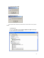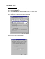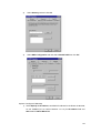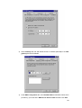
1
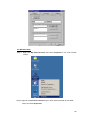
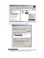
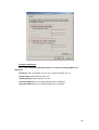
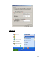
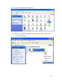
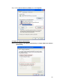
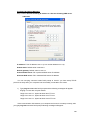
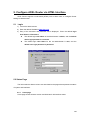
LAM300R
ADSL
Full-Rated Router
User’s Manual
0
Copyright
Copyright © 2004 by this company. All rights reserved. No part of this publication may be
reproduced, transmitted, transcribed, stored in a retrieval system, or translated into any
language or computer language, in any form or by any means, electronic, mechanical,
magnetic, optical, chemical, manual or otherwise, without the prior written permission of this
company.
Disclaimer
This company makes no representations or warranties, either expressed or implied, with
respect to the contents hereof and specifically disclaims any warranties, merchantability or
fitness for any particular purpose. Any software described in this manual is sold or licensed
"as is". Should the programs prove defective following their purchase, the buyer (and not this
company, its distributor, or its dealer) assumes the entire cost of all necessary servicing, repair,
and any incidental or consequential damages resulting from any defect in the software.
Further, this company reserves the right to revise this publication and to make changes from
time to time in the contents hereof without obligation to notify any person of such revision or
changes.
All brand and product names mentioned in this manual are trademarks and/or
registered trademarks of their respective holders.
1
Contents
1 Introduction ................................................................................................................4
1.1 System Requirement ...................................................................................................4
1.2 Package Contents .......................................................................................................4
2 Product Features .................................................................................. 5
2.1 ADSL Compliant...........................................................................................................5
2.2 ATM Protocols and Encapsulations .............................................................................5
2.3 Bridging / Routing ........................................................................................................5
2.4 Security and HTTP Web-based Management.............................................................6
2.5 Interface .......................................................................................................................6
3 Hardware Indicators and Connectors ................................................. 7
3.1 Front Panel Indicators and Description .......................................................................7
3.2 Back Panel...................................................................................................................7
3.3 Connect Related Devices ............................................................................................8
4 Connecting ADSL Router via Ethernet and USB................................ 9
4.1 Setup ADSL Router via Ethernet Cable.......................................................................9
4.2 Setup ADSL Router via USB Cable .............................................................................9
4.3 Configure TCP/IP.......................................................................................................13
5 Configure ADSL Router via HTML Interface ..................................... 24
5.1 Login ..........................................................................................................................24
5.2 Status Page................................................................................................................24
5.2.1 Home Page ...........................................................................................................24
5.2.2 PPP .....................................................................................................................25
5.2.3 ADSL Status Page ...............................................................................................26
5.3 Configuration Pages ..................................................................................................28
5.3.1 WAN Configuration ...............................................................................................28
5.3.2 LAN Configuration.................................................................................................30
5.3.3 PPP Configuration ................................................................................................32
5.3.4 NAT Configuration.................................................................................................34
5.3.5 Virtual Server Configuration..................................................................................36
5.3.6 Bridge Filtering......................................................................................................36
5.3.7 DNS Configuration ................................................................................................37
5.3.8 User Level Username/Password Configuration....................................................39
5.3.9 Save Settings/Reboot ...........................................................................................39
6 Admin Privilege ................................................................................... 40
6.1 WAN Status................................................................................................................40
6.2 ATM Status.................................................................................................................40
6.3 ADSL Configuration ...................................................................................................41
6.4 Route Table................................................................................................................42
2
6.5 Learned MAC Table ...................................................................................................44
6.6 RIP Configuration.......................................................................................................44
6.7 Miscellaneous Configuration......................................................................................47
6.8 TCP Status.................................................................................................................49
6.9 Admin Level Username/Password.............................................................................50
6.10 Reset Factory Default ..............................................................................................50
6.11 Diagnostic Test.........................................................................................................51
6.12 System Log ..............................................................................................................52
6.13 Local Code Image Update .......................................................................................53
6.14 Firewall.....................................................................................................................54
3
1. Introduction
This ADSL Ethernet Router powered by Conexant ADSL Router chipset. It is featuring
“always-on” function and enables high-speed broadband connection from Internet to
end-users. This ADSL Ethernet Router ensures not only maximum performance, but also
significantly simpler handling process. You can access Internet and provide multiple users on
LAN to access Internet (WEB, E-mail, FTP) simultaneously, with one single user account via
one single ADSL line.
This ADSL Ethernet Router is fully compliant with ANSI T1.413 Issue 2, ITU-T G.dmt,
ITU-T G.lite standards. Using existing twisted-pair telephone lines, ADSL technology provides
data rate more than 100 times faster than a traditional analog modem without interruption of
telephone service.
1.1 System Requirements
z
Pentium II 233 MHz processor or higher
z
32 MB RAM minimum
z
20 MB of free disk space minimum
z
Ethernet Network Interface Controller (NIC) RJ45 Port
z
USB Port
z
CD-ROM
1.2 Package Contents
z
ADSL Ethernet Router (LAM300R)
z
RJ-45 Cable
z
RJ-11 Cable
z
USB Cable (for dual mode router only)
z
Power Adapter
z
Software driver CD
z
Quick Guide
If any of above items is missing or damaged, please contact your local dealer
immediately.
4
2. Product Features
2.1 ADSL Compliant
z
ANSI T1.413 issue 2
z
ITU G.dmt (G.992.1)
z
ITU G.lite (G.992.2)
z
ADSL over POTS (Annex A) or ADSL over ISDN (Annex B/UR2)
z
G.994.1 (G.hs, Multimode)
z
Tone detection for low power mode
z
Maximum downstream rate up to 8Mbps
z
Maximum upstream rate up to 1Mbps
2.2 ATM Protocols and Encapsulations
z
ATM Forum UNI 3.0/4.0 PVC
z
Up to 8 VCs (Virtual Circuit)
z
ATM SAR (Segmentation and Reassembly)
z
ATM supports AAL5, UBR & CBR
z
RFC 2516 (PPP over Ethernet)
z
RFC 2364 (PPP over ATM)
z
RFC 1577 (Classical IP over ATM)
z
RFC 1483 BPDU (Bridge Ethernet over ATM)
z
OAM F4 and F5 segment end-to-end loopback (F4 on all VPIs, F5 on VPI 0 only)
z
VPI (0-255), VCI (0-65535)
2.3 Bridging / Routing
z
Ethernet to ADSL self-learning Transparent Bridging (IEEE 802.1D)
z
Supports up to 128 MAC learning address
z
IP routing-RIPv2 (backward compatible with RIPv1)
z
Static routing
z
DHCP (Dynamic Host Configuration Protocol) Server and Client
z
NAPT (Network Address and Port Translation)
z
NAT (Network Address Translation)
z
ICMP (Internet Control Message Protocol)
z
IGMP (Internet Group Management Protocol)
z
Simultaneous USB and Ethernet operation
5
2.4 Security and HTTP Web-based Management
z
PAT (Password Authentication Protocol)
z
CHAP (Challenge Authentication Protocol)
z
User authentication for PPP
z
Firewall
z
Configuration of NAT/NAPT
z
WAN and LAN connection statistics
z
Selection of Bridge or Router Mode
z
Configuration of VCs (Virtual Circuits)
z
DNS Proxy
z
DMZ support
z
MAC Filtering
z
ALG supports MSN Messenger 4.x, H.323 (MS NetMeeting), AOL Instant
Messenger, Windows Media Player, Real Audio, CuSeeMe 5.00, DirectX 8.0,
DirectPlay, IPSec, PPTP VPN pass-through, L2TP VPN pass-through, HTTPS,
HTTP, FTP, ICMP, SMTP, POP3, NNTP, Telnet, Age of Empires 2, StartCraft,
Diablo (Blizzard), Quake 2/ Wuake 2 Server, Quake 3, Doom, Half Life Counter
Strike/ Team Fortress Classic, Return to Castle Wolfenstein, Unreal Tournament,
EverQuest, Warcraft (Blizzard)
2.5 Interface
z
LAN: 10/100 Base-T auto sensing Ethernet port through RJ-45 connector
(IEEE 802.3)
z
ADSL: ADSL line through RJ-11 connector
z
USB: 1.1 compliant, maximum transferring rate up to 12Mbps
6
3. Hardware Indicators and Connectors
3.1 Front Panel Indicators and Description
○
○
○
○
○
○
○
○
DATA
ADSL
4x
3x
2x
1x
USB
PWR
Descriptions of LED status
DATA
ADSL
When router is transferring data between Internet and router, this LED will be flashing.
When connection with Internet (ADSL Connected) is established, this LED will light up.
When this LED is flashing: NO ADSL physical connection
4x
When port 4 connection with end user is established, this LED will light up.
3x
When port 3 connection with end user is established, this LED will light up.
2x
When port 2 connection with end user is established, this LED will light up.
1x
When port 1 connection with end user is established, this LED will light up.
USB
When an active USB cable is connected with router, this LED will light up.
PWR
When an active power adapter is connected with router, this LED will light up.
3.2 Back Panel
LINE
USB
1X
2X
3X
4X
PWR
DEFAULT
Descriptions of All Connectors
LINE
Connect with telephone line.
USB
Connect with USB cable.
1x
Connect with Ethernet Cable to Switch Hub.
2x
Connect with Ethernet Cable to Switch Hub.
3x
Connect with Ethernet Cable to Switch Hub.
4x
Connect with Ethernet Cable to Switch Hub.
PWR
DEFAULT
Connect with power adapter.
Reset button.
7
3.3 Connect Related Devices
1) Connect Router to LINE
Plug the provided RJ-11 cable into LINE port on the back panel of the router and
insert the other end into splitter or wall phone jack.
2) Connect Router to LAN
Plug RJ-45 Ethernet Cable into LAN port on the back panel of the router and insert
the other end of the Ethernet Cable on your PC’s Ethernet port or switch / hub.
3) Connect Router to Power Adapter
Plug power adapter to PWR port on the back panel of the router and the other end to
a power outlet.
The diagram below illustrates a connection example,
Warning! Only use the power adapter provided in the package, otherwise it may cause
hardware damage.
8
4. Connecting ADSL Router via Ethernet and USB
You can connect ADSL router with PC through either Ethernet cable or USB cable.
After connection is established, you can configure the host PC to be a DHCP client. You have
to repeat the same steps for every host PC on your network if you use DHCP function on your
router.
4.1 Setup ADSL router via Ethernet Cable
If there is an available Networking LAN card present on your PC, you just simply connect
ADSL router and PC through the Ethernet cable. Once you establish Internet connection, you
could browse the Web through the Ethernet cable.
4.2 Setup ADSL router via USB Cable
You can connect ADSL router with PC via USB cable when there is no Networking LAN
Card present on your PC. USB cable acts as another LAN connection in this scenario. Once
you establish Internet connection, you could browse the Web through the USB cable.
USB Device Driver Installation
Step1: Connect ADSL Router and PC with USB cable.
Step2: Once “Detect New USB Device” window pops out, click “cancel”:
For windows 98, 98SE and ME:
9
For Windows 2000 and XP:
Step 3: Insert “Easy Setup Software Kit” CD then click Install USB Driver to install
device driver. This USB installation utility automatically loads device driver.
After USB device driver installation completes, the window below will appear, then press
“OK” to reboot your computer.
10
For windows 98, 98SE and ME:
For Windows 2000 and XP:
After computer reboot, follow the procedures below to check if ADSL router is properly
installed.
For Windows XP:
Go through “Start Æ Control Panel Æ System Æ Hardware Æ Device Manager”
to check if USB device is installed properly:
11
FOR Windows 2000:
Go through “Start Æ Settings Æ Control Panel Æ System Æ Hardware Æ
Device Manager” to check if USB device is installed properly:
For Windows 98, 98SE and ME:
After OS boots up, go through “Start Æ Settings Æ Control Panel Æ System Æ
Device Manger” to check if USB device is installed properly:
12
4.3 Configure TCP/IP
For Windows 98 and ME
Step 1: Click Start then Settings and choose Control Panel
Step 2: Double click Network icon.
Step 3: Select Configuration tab, then choose TCP/IP from the list of installed network
Components and click Properties button.
Step4: You can setup the following configurations in two methods:
Option1: Get an IP from Router Automatically
1)
Choose Obtain an IP address automatically option in the next window
13
2)
Select Gateway tab and click OK
3)
Select DNS Configuration tab and select Disable DNS then click OK
Option2: Configure IP Manually
1) Select Specify an IP address, set default IP address for the Router is 10.0.0.2,
so use 10.0.0.X (X is a number between 4 to 15) for IP Address field and
255.0.0.0 for Subnet Mask field.
14
2) Select Gateway tab and add default Router IP Address (10.0.0.2) in the New
gateway field and click Add.
3) Under DNS Configuration tab, select Enable DNS and add DNS values which
provides by your local ISP in DNS Server Search Order field then click Add.
15
For Windows 2000
Step 1: Right click My Network Places and select Properties in the main window
screen:
Step 2: Right click Local Area Connection (your local network hooked up with ADSL
router) and select Properties:
16
Step 3: Select Internet Protocol (TCP/IP) then click Properties:
Configure IP Automatically:
Step 4: Select Obtain an IP address automatically and Obtain DNS server address
automatically then click OK to complete IP configuring process.:
17
Configure IP Manually:
Step 4: Select Use the following IP address and Use the following DNS server
addresses.
IP address: Fill in IP address 10.0.0.x (x is a number between 4 to 15).
Subnet mask: Default value is 255.0.0.0.
Default gateway: Default value is 10.0.0.2.
Preferred DNS server: Fill in preferred DNS server IP address.
Alternate DNS server: Fill in alternate DNS server IP address.
18
For Windows XP
Step 1: Click Start then select Control Panel in the main window screen:
19
Step 2: Double click Network Connections icon:
Step 3: Right click Local Area Connection (local network your ADSL hooked up with)
then select Properties:
20
Step 4: Select Internet Protocol (TCP/IP) then click Properties:
Configure IP address Automatically:
Step 5: Select Obtain an IP address automatically and Obtain DNS server address
automatically:
21
Configure IP Address Manually:
Step 5: Select Use the following IP address and Use the following DNS server
addresses.
IP address: Fill in IP address 10.0.0.x (x is a number between 4 to 15).
Subnet mask: Default value is 255.0.0.0.
Default gateway: Default value is 10.0.0.2.
Preferred DNS server: Fill in preferred DNS server IP address.
Alternate DNS server: Fill in alternate DNS server IP address.
You can use ping command under DOS prompt to check if you have setup TCP/IP
protocol correctly and if your computer has successfully connected to this router.
1) Type ping 10.0.0.2 under DOS prompt and the following messages will appear:
Pinging 10.0.0.2 with 32 bytes of data:
Reply from 10.0.0.2 : bytes=32 times<2ms TTL=64
Reply from 10.0.0.2 : bytes=32 times<1ms TTL=64
Reply from 10.0.0.2 : bytes=32 times<10ms TTL=64
If the communication link between your computer and router is not setup correctly, after
you type ping 10.0.0.2 under DOS prompt following messages will appear:
22
Pinging 10.0.0.2 with 32 bytes of data:
Request timed out.
Request timed out.
Request timed out.
This failure might be caused by cable issue or something wrong in configuration procedure.
23
5. Configure ADSL Router via HTML Interface
ADSL Router supports a web-based (HTML) GUI to allow users to configure Router
setting via Web browser.
5.1 Login
1) Launch the Web browser.
2) Enter the default IP address http://10.0.0.2.
3) Entry of the username and password will be displayed. Enter the default login
User Name and Password.
z
The default login User Name of the administrator is admin, and the default
admin login password is conexant.
z
The default login User Name for the non-administrator is user, and the
default user login password is password.
5.2 Status Page
The links under the Status column are associated to the pages that represent the status
of system and interfaces.
5.2.1
Home page
Home page shows firmware version and WAN and LAN interface status.
24
Firmware Version: This field displays the Conexant firmware version number.
Customer Software Version: This field displays the customer’s own firmware version
number.
WAN: These fields display the IP address, Subnet Mask and MAC address for the WAN
(ADSL) interface.
LAN: These fields display the IP address, Subnet Mask and MAC address for the LAN
interface.
Total Number of LAN Interface: This field displays the total number of available
interface for the LAN interface.
Number of Ethernet Devices Connected to the DHCP Server: These fields display
the DHCP client table with the assigned IP addresses and MAC addresses.
5.2.2
PPP
The PPP Status page shows the status of PPP for each PPP interface.
25
PPP: These fields display the Connection Name (user defined), Interface (PVC), Mode
(PPPoE or PPPoA), Status (Connected or Not Connected), Packets Sent, Packets
Received, Bytes Sent and Byte Received.
Connect and Disconnect: This Field allows the user to manually connect/disconnect
the PPP connection for each PPP interface. In another word, each PPP session can be
connected and disconnected individually.
5.2.3
ADSL Status Page
The ADSL Status page shows the ADSL physical layer status.
26
Showtime Firmware Version: This field displays the Conexant ADSL data pump
firmware version number.
ADSL Line Status: This field displays the ADSL connection process and status.
ADSL Modulation: This field displays the ADSL modulation status for G.dmt or T1.413.
ADSL Annex Mode: This field displays the ADSL annex modes for Annex A or Annex B.
ADSL Startup Attempts: This field displays the ADSL connection attempts after loss of
showtime.
ADSL Max Tx Power: This field displays the transmit output power level of the CPE.
ADSL CO Vendor: This field displays the Central Office DSLAM vendor name, if
available.
Elapsed Time: This field displays the time of the router has been in operation.
SNR Margin: Amount of increased noise that can be tolerated while maintaining the
designed BER (bit error rate). The SNR Margin is set by Central Office DSLAM. If the
SNR Margin is increased, bit error rate performance will improve, but the data rate will
decrease. Conversely, if the SNR Margin is decreased, bit error rate performance will
decrease, but the data rate will increase.
Line Attenuation: Attenuation is the decrease in magnitude of the ADSL line signal
between the transmitter (Central Office DSLAM) and the receiver (Client ADSL Router),
measured in dB. It is measured by calculating the difference in dB between the signal
power level received at the Client ADSL router and the reference signal power level
transmitted from the Central Office DSLAM.
27
Errored Seconds: The error during Showtime, whenever, a given see contains CRC
error, that second will be declared error second.
Loss of Signal: This field displays the count of event of ADSL signal loss.
Loss of Frame: This field displays the count of event of ADSL frame loss.
CRC Errors: This field displays the number of transmit data frames containing CRC
rrors.
Data Rate: This field displays the ADSL data rate.
Latency: This field displays the latency modes for fast or interleave.
5.3 Configuration Pages
The links under Configuration column are associated to the pages that represent the
configurations of system and interfaces. When the configurations are changed, please go to
the Save Settings/Reboot page to save the new settings and reboot the ADSL router.
5.3.1
WAN Configuration
The WAN configuration page allows the user to select Pvc adapter then set the
configuration for the WAN/ADSL ports which includes ATM, DHCP Client, MAC Spoofing,
Static IP Settings and PPP.
28
ATM: ATM configuration includes setting up VPI, VCI, Peak Cell Rate, Sustainable Cell
Rate, Max Burst Size and Service Category of the connection.
DHCP Client: When enable this feature, you have to fill in DHCP Host name.
MAC Spoofing: The MAC Spoofing is developed to solve the scenario when the ISP
only recognizes one MAC address. Enter the ISP recognized MAC address here.
Static IP Settings: You are able to fill in ADSL router IP Address, Subnet Mask and
Gateway.
PPP: You can fill in basic and advanced PPP configurations that include user login
information and router disconnection criteria.
29
WAN
Bridge Mode
Configuration
IP address
N/A
Router Mode
Router Mode
Router Mode
(PPPoA/PPPoE)
(Dynamic IP)
(Static IP)
Automatically
Automatically assigned by ISP
Provided by ISP
Automatically assigned by ISP
Provided by ISP
Automatically assigned by ISP
Provided by ISP
assigned by ISP
Subnet Mask
N/A
Automatically
assigned by ISP
Gateway
N/A
Automatically
assigned by ISP
Encapsulation
1483 Bridged IP
PPPoA LLC/VC-Mux 1483 Bridged/Routed IP LLC,
LLC, 1483 Bridged PPPoE LLC/VC-Mux 1483 Bridged/Routed VC-Mux
Classical IP over ATM
IP VC-Mux
1483 Bridged/Routed IP
LLC, 1483 Bridged/Routed
VC-Mux, Classical IP over
ATM
Bridge
Enabled
Disabled
Disabled
Disabled
PPP Service
N/A
Provided by ISP
N/A
N/A
PPP User name N/A
Provided by ISP
N/A
N/A
DHCP Client
Unchecked
Checked
Unchecked
Unchecked
enable
5.3.2
LAN Configuration
The LAN configuration page allows the user to set the configuration for the LAN
connection.
30
LAN IP Address & Subnet Mask: The default is 10.0.0.2 and 255.0.0.0. User can
change it to other private IP address, such as 192.168.1.2, and 255.255.255.0.
DHCP Server
System Allocated: The DHCP address pool is based on LAN port IP address plus
12 IP addresses. For example, the LAN IP address is 10.0.0.2; the DHCP address
pool is at the range 10.0.0.3 to 10.0.0.14.
User Defined: The DHCP address pool is at the range of USER Defined Start
Address and User Defined End Address. The maximum pool size can be 253 IP
addresses: 255 total IP addresses – 1 broadcast address – 1 LAN port IP address.
DHCP Gate Selection: The default setting for the DHCP Gateway Selection is
“Automatic”. The user can select the “User Defined” to specify “User Defined
Gateway Address”. The DHCP server will issue the “User Defined Gateway
Address” to the LAN DHCP clients.
Lease time: The Lease time is the amount of time of a network user will be allowed
to connect with DHCP server. If all fields are 0, the allocated IP addresses will be
effective forever.
DHCP Relay: DHCP Relay feature allows you to use DHCP on a subnet that does
not have DHCP server by installing DHCP Relay Agent.
DHCP Relay Target ID: The subnet that needs to install DHCP Relay Agent.
User mode: Under the Single User mode, the DHCP server only allocates one IP
address to local PC. Under the Multiple User mode, the DHCP server allocates the
IP addresses specified by the DHCP address pool.
Ethernet Mode Setting
You are allowed to select Ethernet connection mode in this page. You can choose
from AutoSense, 100 Full, 100 Half, 10 Full and 10 Half Ethernet modes.
31
5.3.3
PPP Configuration
The PPP Configuration page allows the user to configure multiple PPP sessions for
each PVC. It can support up to total of 16 PPP sessions, and each PVC can support up to 8
PPP sessions. The multiple PPP sessions may be configured with any combination over 8
PVCs.
32
Session Name: This field allows the user to enter his/her own session Name to
distinguish different session for different PPP accounts and different PVCs.
PVC: This field allows the user to choose the specific PVC for PPP session.
Service Name: The service name of PPP is required by some ISPs. If the ISP does
not provide the Service Name, please leave it blank.
Account to Use: Choose which PVC to connect.
Disconnect Timeout: The Disconnect Timeout allows the user to set the specific
period of time to disconnect from the ISP. The default is 0, which means never
disconnect from the ISP.
MRU: Maximum Receive Unit indicates the peer of PPP connection the maximum
size of the PPP information field this device can be received. The default value is
1492 and is used in the beginning of the PPP negotiation. In the normal negotiation,
the peer will accept this MRU and will not send packet with information field larger
than this value.
MTU: Maximum Transmission Unit indicates the network, stack of any packet is
larger than this value will be fragmented before the transmission. During the PPP
negotiation, the peer of the PPP connection will indicates its MRU and will be
accepted. The actual MTU of the PPP connection will indicates its MRU and will be
accepted. The actual MTU of the PPP connection will be set to the smaller one of
MTU and the peer’s MRU. The default is value 1492.
MSS: Maximum Segment Size is the largest size of data that TCP will send in a
single IP packet. When a connection is established between a LAN client and host
in the WAN side, the LAN client and the WAN host will indicate their MSS during the
TCP connection handshake. The default value is 1432.
LCP Echo Interval: Time interval that determines when a link is functioning
properly and when it is defunct, detect a looped-back link and other common
mis-configuration errors.
LCP Echo Maximum Consecutive Failure: The maximum number of LCP Echo
failures router receives before terminate the link.
Authentication: When AUTO option is chosen, the PAP mode will run first then
CHAP.
Automatic Reconnect: When it is checked, it will maintain the PPP connection all
the time. If the ISP shut down the PPP connection, it will automatically reconnect
PPP session.
PPP Disconnect Timer Configuration
You can set PPP Disconnect Timer by selecting the criteria you desired.
33
5.3.4
NAT Configuration
The NAT Configuration page allows the user to set the configuration for the Network
Address Translation. The default setting is Dynamic NAPT. It provides dynamic Network
Address Translation capability between LAN and multiple WAN connections, and the LAN
traffic is routed to appropriate WAN connections based on the destination configuration
between multiple LAN clients and multiple WAN connections.
When the Dynamic NAPT is chosen, there is not need to configure the NAT Session and
NAT Session Name Configuration.
34
Session Name: This field allows the user to select the session from the configured
NAT session Name Configuration.
User’s IP: This filed allows the user to assign the IP address to map the
corresponding NAT/NAPT sessions.
Session Name Status will be displayed at the middle of this page to show the
corresponding Session Name with its IP address.
Number of NAT Configurations: This filed displays the total number of NAT
Sessions is entered.
Available Sessions Status will be displayed at the end of this page to show all the
Session Names with its WAN Interface.
Number of Session: This filed displays the total number of NAT Sessions Name is
entered.
The NAT option only maps single WAN IP address to the local PC IP address. It is
peer-to-peer mapping. (1x1) For each WAN interface, only one local PC IP address can be
associated with each WAN interface. Click the link Session Name Configuration to add the
session name for WAN interface.
The NAPT option maps the single WAN IP addresses to many local PCs IP addresses.
(1xN). It is the multiple-mapping mechanism. For each WAN Interface, more than one local
PCs can be associated with one WAN Interface. Click the link Session Name Configuration
to add the session name for WAN interface.
35
Session Name: This field allows the user to enter his/her own session Name to
distinguish different NAT session for different interfaces among different PPP
sessions and different PVCs.
Interface: This field allows the user to choose specific WAN Interface (PVC or PPP
Session) for NAT Session.
Click the link Go back to NAT Configuration to the NAT configuration page. Select
the NAT option. Select the Session Name and assign the PC IP address, and choose the Add
action. Click the Submit button and go to the Save Settings to save this configuration.
NAT allows only one entry (User IP) per session. NAPT allows many entries (User
IPs) per session.
5.3.5
Virtual Server Configuration
The Virtual Server Configuration page allows the user to set the configuration of
Virtual Server. The Conexant firmware includes the Free BSD version firewall. All UDP/TCP
ports are protected from intrusion. If any specific local PCs need to be mapped to the
UDP/TCP port on WAN side, please input the mappings here.
36
Public Port Start: This field allows the user to enter the start of port number for
public network.
Public Port End: This field allows the user to enter the end of port number for
public network.
Private Port: This field allows the user to enter the port number of the Private
Network. In most cases, the private port number is same as public port number.
Port Type: User can choose port type between TCP and UDP.
Host IP Address: This field allows the user to enter the private network IP address
for the particular sever.
5.3.6
Bridge Filtering
The Bridge Filtering configuration page allows the user to set the configuration of IP
filtering. User can block data from the exact MAC address or forward data to the exact MAC
address.
37
Source MAC: When the bridge filtering is enabled, enter the Source MAC
address, select Block and click Add. Then all incoming WAN and LAN Ethernet
packets matched with this source MAC address will be filtered out. If the Forward is
selected, then the packets will be forwarded to the destination PC.
Destination MAC: When the bridge filtering is enabled, enter the Destination
MAC address, select Block and click Add. Then all incoming WAN and LAN
Ethernet packets matched with this destination MAC address will be filtered out. If
the Forward is selected, then the packets will be forwarded to the destination PC.
Type: Enter the hexadecimal number for the Ethernet type field in Ethernet_II
packets. For example, 0800 is for IP protocol.
5.3.7
DNS Configuration
This DNS Configuration page allows the user to set the configuration of DNS proxy.
The Conexant firmware supports the DNS proxy function. For the DHCP requests from local
PCs, the DHCP server will set the LAN port first. The DNS proxy on the ADSL router recorded
the available DNS servers, and forward DNS query messages to one of DNS server.
38
DNS Proxy: User can enable or disable DNS Proxy feature.
For the DHCP
requests from local PCs, the DHCP server will set the user-configured preferred
DNS server or alternate DNS server whichever is available as the DNS server.
Then all DNS query messages will be directly sent to the DNS servers.
Auto Discovered DNS Servers Only: The DNS proxy will store the DNS server IP
addresses obtained from DHCP client or PPP into the table. And all DNS query
messages will be sent to one of the dynamically obtained DNS servers.
User Configured DNS Servers Only: The DNS proxy will use the user-configured
DNS server and alternate DNS server. And all DNS query message will be sent to
one of DNS servers. Enter the DNS IP in the Preferred DNS Server and Alternate
DNS Server fields.
DNS Server: User enters DNS server’s name that will be deleted or added from
network.
DNS Server: User can enable or disable DNS server here.
URL Name: DNS server’s URL name.
Host IP: Host DNS server’s IP.
39
5.3.8
User Level Username/Password Configuration
This page allows user to set private user’s name and login password.
5.3.9
Save Settings/Reboot
After user modify ADSL router configuration settings, user can save the changes and
reboot the router or ignore the changes and reboot the router.
40
6. Admin Privilege
The links under Admin Privilege are only to be accessed and configured when user
logs in with the administrator login name and password.
6.1 WAN Status
The WAN Status page shows the information and status of WAN PVCs that includes
network IP Address, Subnet Mask and MAC Address.
Virtual Circuit: ADSL router supports eight virtual circuits, user can release or add
virtual circuits in the page.
6.2 ATM Status
The ATM Status page shows all the statistics information of transmit/receive cells.
41
Reset Counter: This button allows user to reset the ATM Status counter.
6.3 ADSL Configuration
This page allows user to configure ADSL router Annex mode, handshaking protocol,
wiring selection and bit swapping options.
42
Annex Mode Config: This option includes User Selected which user allows to select
Annex mode and Auto Selected which ADSL router automatically select appropriate
Annex mode.
User Selected Annex Mode: This feature enables when user select User Selected
mode in Annex Mode Config. It has Annex A and Annex B two options.
Trellis: Trellis code provides a level of forward error correction to ADSL router. User
can either enable or disable this function.
Handshake Protocol: This feature allows user to choose Autosense-G.dmt first /
Autosense-T1.413 first / G.dmt/G.lite/T1.413 / G.dmt / G.lite communication
protocols.
Wiring Selection: This field allows the user to enter the wiring selection for the RJ-11.
Tip/Rip is the default for the board without the inner/outer pair relay. This feature
allows user to choose from Auto / Tip/Ring / A/A1 wiring selection.
Bit Swapping: This field allows the user to enable or disable the upstream bit swapping.
6.4 Route Table
The Route Table page displays routing table and allows the user to manually enter the
routing entry. The routing table will display the routing status of Destination, Netmask, Gateway,
and Interface. The interface br0 means the USB interface; lo0 means the loopback interface;
and ppp1 means the PPP interface.
43
Route Table
The Route Table displays existing ADSL router USB connection and Ethernet
connection routing information. It includes Destination, Netmask and Gateway address.
System Default Gateway Configuration
The system-wide Default Gateway now provides three options: None, Auto, select
Interface, and Specify IP.
None: This field allows the user to choose whether Default Gateway in the CPE is
needed.
Auto: This field allows the user to select the CPE to automatically decide the
Default Gateway. (System Default)
Selecte Interface: This field allows user to select a Network Interface from a list
(PVCs, PPP Sessions, USB and LAN). This option lets the user to associate the
system-wide Default Gateway to a Network Interface, static or dynamic, and
provides a way to fix the Default Gateway to a dynamic Network Interface before
the interface is established.
Specify IP: User can specify Gateway IP address.
Route Configuration
This field allows user to add or remove specified Destination address, Netmask address,
specified Gateway IP address and select connection interface.
6.5 Learned MAC Table
The Learned MAC Table page displays MAC address and expiration time.
44
Aging Timeout: This field allows the user to enter the update period for the MAC
table.
6.6 RIP Configuration
The RIP Configuration page allows the user to set the configuration for the system wide
configuration of RIP. The actual RIP configuration is in the RIP per Interface Configuration.
RIP: This field allows the user to Enable or Disable the RIP session. The resulting
RIP session will monitor all network interfaces that are currently available for
messages from other RIP routers.
Border Gateway: This field allows user to enable or disable border gateway.
Supplier Interval: This field allows the user to enter the Supplier Interval timer in
second.
This timer specifies how often RIP sends announcements as a RIP
Supplier. (Default = 30 seconds)
Expire Timeout: This field allows the user to enter the Expire timer in second.
This timer specifies the expiration time of a route. When a route has not been
updated for more than “expire” period of time, it is removed from the Route Table.
This route is invalidated and remains in the internal RIP Route Table. It will be
included in the RIP announcements to let other routers know the changes.
(Default = 180 seconds)
45
Garbage Timeout: This field allows the user to enter the Garbage timer in second.
This timer specifies how long the expired and invalidated routes are kept in the
Internal RIP Route Table before it is removed from it. (Default = 300 seconds)
Advanced Configuration
The RIP Per Interface Configuration page allows the user to set the configuration for
each Interface (PVCs, PPP Sessions, USB and LAN) and displays current RIP settings.
Interface: This field allows the user to choose the Interface (PVCs, PPP Sessions,
USB and LAN), for the RIP to be configured.
Enable?: This field allows the user to Enable (Yes) or Disable (No) the specified
interface for RIP.
Supplier: This field allows the user to select the Supplier Mode (RIP Transmit).
1) Disabled: The supplier transmit is disabled.
2) V1 BC: The supplier transmits in RIPv1 Broadcast.
3) V2 BC: The supplier transmits in RIPv2 Broadcast.
4) V2 MC: The supplier transmits in RIPv2 Multicast.
Listener: This field allows the user to select the Listener Mode (RIP Receive)
1) V1: The listener receives the RIPv1 only.
2) V2: The listener receives the RIPv2 only.
3) V1+V2: This listener receives the both RIPv1 and RIPv2.
46
Supplier and Listener are based on section 4.1 “Compatibility Switch” in RFC 1723.
Current RIP Settings: This field displays the each interface’s RIP status.
6.7 Miscellaneous Configuration
The Miscellaneous Configuration allows user to set all the miscellaneous
configurations, which include HTTP server, FTP server, TFTP, DMZ, IGMP, PPP, and SNTP
setup configuration.
HTTP Server Access: This field allows the user to configure the Web pages can
be accessed from.
ALL: When this field is checked, it allows both WAN and LAN access to the Web
pages.
Restricted LAN: This field allows the Web pages access from LAN side.
Restricted WAN Specified IP & Subnet Mask: This field allows the Web access
from WAN side with a specify IP and subnet mask.
HTTP Server Port: This field allows the user to specify the port of the Web access.
For example, when it is changed to 1001, the HTTP server address for the LAN
side is http://10.0.0.2:1001.
HTTP Password Protection: This field allows user to enable or disable password
protection for HTTP server.
FTP server: This field allows the user to enable or disable the FTP connection.
TFTP server: This field allows the user to enable or disable the TFTP connection.
47
An example for the TFTP client updating the vxworks.z product image code is:
DMZ: A DMZ (De-Militarized Zone) is added between a protected network and an
external network, in order to provide an additional layer of security. When there is a
suspected packet coming from WAN, the firewall will forward this packet to the DMZ
host.
DMZ Host IP: The IP address of the DMZ host at LAN side.
IGMP Proxy: Here is the global setting for IGMP Proxy. If it is enabled, then the
enabled IGMP Proxy on WAN PVCs will be working. Otherwise, no WAN PVC can
have IGMP Proxy working on it.
PPP Half Bridge: When the PPP Half Bridge is enabled, only one PC is able to
access the Internet, and the DHCP server will duplicate the WAN IP address from
the ISP to the local client PC. Only the PC with the WAN IP address can access the
Internet.
Q: What is the difference between PPP connect on WAN access and the Automatic
Reconnect?
A: Some ISPs terminated the PPP session due to the inactivity.
PPP reconnect on WAN access: If it is enabled, the PPP will be automatically
reconnected when an URL is entered in the browser (packet interested in going out
the WAN).
Connect PPP when ADSL link is up: If it is enabled, the PPP session will be
automatically established when ADSL link is available.
48
SNTP: This field allows user to set time zone and enable/disable daylight saving
time option.
6.8 TCP Status
The TCP Status page shows the statistics for all TCP connections.
Reset Counter: This button allows user to reset the TCP Status counter.
6.9 Admin Level Username/Password
This page allows user to set administrator level user’s name and password.
The Admin password must has at least 8-characters for the FTP to work
49
6.10 Reset to Factory Default
The Reset to Factory Default page allows the user to reset the router to original factory
default configuration.
After click Submit button, ADSL router settings will be set to factory default and reboot router.
Wait for about 5 to 10 seconds, router will boot up and ready to use.
50
6.11 Diagnostic Test
The Diagnostic Test page shows the test results for the connectivity of the physical
layer and protocol layer for both LAN and WAN sides.
51
Testing Ethernet LAN Connection: This test checks the Ethernet LAN interface
connection.
Testing ADSL Synchronization: This test checks the ADSL showtime. If this test
returns FAIL, all other tests will be skipped.
Test ATM OAM Segment Loop Back: This test sends ATM OAM F5 Segment
loop back request cells to the CO. This test will pass if response cell is received.
Since some service providers might not support this test, it could still work even if
this test fails. If this test fails consistently and the ADSL router seems not working,
make sure the VPI and VCI are configured correctly.
Test Ethernet Connect to ATM: This test checks the ATM AAL5 module is loaded
correctly.
Test PPPoE Connection: This test checks the PPPOE connection.
Test PPP Layer Connection: This test checks the PPP authentication.
Test IP Connect to PPP: This test checks a valid IP address assigned from the
service provider.
Ping Primary DNS: This test checks the primary DNS can be reached through ping
request.
Query DNS for www.lgnetwork.com : This test checks the host name can be
resolved to IP address though domain name servers.
Ping www.lgnetwork.com : This test checks the specified host can be reached
through ping request.
6.12 System Log
The System Log page shows the events triggered by the system.
52
Clear Log: This field allows the user to clear the current contents of the System
Log.
Save Log: This field allows the user to save the current contents of the System Log
by right click HERE and select “Save Target As” to save it into a text file.
The System Log records:
1) DSL Layer
z
DSL Link detected
z
DSL Link connected
z
DSL Link disconnected
2) ATM Layer
z
ATM detected
z
ATM connected
z
ATM disconnected
z
ATM setting up VPI/VCI
3) PPP Layer
z
PPP authenticated
z
PPP invalid user name or password
z
PPP unable to connect with PPP server
4) IP Layer
z
IP protocol up
z
PPP IP address
z
PPP Gateway IP address PPP DNS Primary IP address
z
PPP DSN Secondary IP address
6.13 Local Code Image Update
The Local Code Image Update page allows the user to upgrade the image code locally.
53
Click Image Download button to start update the code image.
Browse the location of file, firmware.dlf or boorom.dlf file, and click the Upload to start
the update. If you decide to abort code update, click Cancel Download button.
54
6.14 Firewall
Conexant firewall allows users to configure various databases/firewall options and
Inbound/Outbound policies for controlling Inbound/Outbound traffic.
Firewall: User can enable or disable firewall feature of the ADSL router at the bottom of this
page.
z
Advanced Options
Advanced options include Protection Policy, Hacker Log and Service Filtering.
Protection Policy
55
Basic Protection: Firewall blocks IP Spoofing, Ping of Death, Land Attack and
Ressambly Attack.
Advanced Protection: Firewall blocks SYN Flooding, ICMP Redirection, Source
Routing and Winnuke Attack.
Hacker Log
This page allows user to select which hacker attack router will build attack log.
56
Service Filtering
User can select which service from external network firewall should block.
These
services include Ping, Telnet, FTP, DNS, IKE, RIP and DHCP.
z
Firewall Databases
IP Group database, Service Group database and Time Window database are
configurable to set inbound/outbound policies.
IP Group
User can add new IP group or modify the existing IP group.
57
Service Group
User can add new service group or modify existing service group in this page.
Time Window
User can add new Time Window group or modify existing Time Window group by setting
time duration.
z
Inbound/Outbound Policies
User can set inbound and outbound policies to control the data transmission.
Inbound Policy
User can add new inbound policy to control the data transmission.
58
59
Outbound Policy
User can add new outbound policy to control the data transmission.
60
If you have any troubles to configure or setup this Four-Port ADSL Ethernet Router,
please contact us.
Before contacting us, make sure collect following information. Submit complete
detailed information of your problem will help us to provide you accurate answers.
Model Name:
Serial Number:
PC Settings:
Other:
61