1
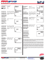
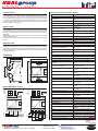
© KRALgroup - N_a 20140319 - SINUSall VERIFIED TYPE The energy meter SINUS with MID conformity marking on the basis of type test certificate can measure the electrical active energy as billing meter. When used as a billing meter in the Approvals / Certificates for shared modes are observed and to observe the functionality according to the name plate! SINUS 85 M-Bus SINUS 85 SO MORE FEATURES .cz .cz SINUS 85 S0 & SINUS 85 M-Bus SINUS 5ll1 S0 & SINUS 5ll1 M-Bus Three-phase static energy meter for alternating voltage with changes valid to: 19.3.2014 Features and specifications are subject to change. USER MANUAL Meinlinova 309/8 CZ-190 16 Praha 9 - Koloděje : 602 360 501(2) : 281 970 988 : [email protected] http://www.kralgroup.cz © KRALgroup For the energy meter valid conditions of extended electromagnetic immunity in the range from 2 kHz to 150 kHz according to the requirements of the EMC Directive EN 50082-2 "Guidelines for the evaluation of the reliability and stability of the meters and ancillary measurement devices" (suitability of the inverter). Connect to the network without neutral conductor is allowed only for the type of SINUS 5ll1, which does not affect the metrological characteristics of the meter in the measure borders of the exposure limit values. Special auxiliary power meter is not necessary. An optional second impulse output for reactive energy is idle or, alternatively, is used for data transmission over a data communications interface M-Bus. REFERENCES TO REGULATIONS AND STANDARDS The active energy unit measurement corresponds to the standards DIN EN 50470-1:2006 and EN 50470-3:2006 The reactive energy unit corresponds to the standards DIN EN 62052-11:2003 and DIN EN 62053-23:2003 The energy meter type test certificate meets the MID Directive 2004/221/ES Based unit complies with the EMC Directive 2004/108/EC Pulse output conforms to the standard DIN EN 62053-31:1999 for passive pulse output class A and or B Width of the energy meter complies with the DIN 43880:1988 with size 1 and width of the meter cover 72mm Mounting on 35 mm standard DIN rail (TH 35) according to DIN EN 60715:2001 Protection level for energy meter and its cover respect standard DIN EN 60529:1992 Capacity of cables and wires complies with DIN VDE 0298-4:2003 standards Torques for terminal screws of the terminals are specified in DIN EN 60999-1:2000 standard Slotted-head screwdriver standardized in DIN 5264:2006-01 and DIN ISO 8764-1:2006-01 standards SAFETY INSTRUCTION ! WARNING! Device installation and use must be carried out only by qualified staff. Switch off the voltage before device installation. Reprinting/transcript of this document or any kind of reproduction - even in part is not permitted without the prior written permission of either the company TIP Thüringer Industrie Produkte GmbH or company KRALgroup. The content and the technical specification of this User Manual are subject to change without prior notice. They do not represent any contractual obligation. KEEP THIS INSTRUCTION MANUAL - CONTAINS, I.A., EU-DECLARATION OF CONFORMITY TYPE SINUS 85 is an electronic, four-wires, three-phase energy meter, direct connected for active power measurement in AC unbalanced electricity network. SINUS 5ll1 is an electronic, four-wires, three-phase energy meter, indirect connected for active power measurement in AC unbalanced electricity network. The energy meter complies with all safety requirements placed on it by law if used properly. Any use outside of its determination may cause interference, malfunctions, hazards or damage to the meter itself and or damage to other equipment. Meters with mechanical damage, manipulated or with open cover and or visibly dropped, in any case shall not be installed and or commissioned. The meter may be used only for its intended purpose. Work on the electrical equipment may only be performed by duly trained specialist personnel with the appropriate permissions. It is necessary to observe and respect the safety regulations and measures adopted and adhered to. INSTALLATION PLACE The meter can be firmly installed in the installation box (UV Cabinet, switchboard cabinet, small apartment switchboard etc.) with the protection class IP54 or higher on a standard DIN rail 35 mm according to DIN EN 60715:2001 standard. For billing measurement unobstructed view must be ensured permanently dependent on the on the meter register (readability of register). Installation on standard meter plate according to the DIN 43853 is not allowed without the mounting adapter and not possible without additional coverage. DIRECT CONNECTED ENERGY METER SINUS 85 USAGE The energy meter SINUS is fully electronic, four-wires meter working independently and to be permanently installed in three-phase four-wires electricity networks and designed to measure electrical active and reactive energy and register up to two energy tariffs. The meter is designed for indoor or residential installations and for installation in control cabinets for DIN rail mounting with size of the 4 modules (4-TE). Type of connection: The energy meter SINUS 85 is designed for direct connection to low-voltage networks up to 85 A current limit. The energy meter is equipped with terminals for control voltage for tariff switching and active energy pulse output. The meter. The energy meter SINUS 5ll1 is designed for indirect connection to low-voltage network to be connected to the current transformers with secondary current of 5 A or 1 A. The installation of the meter is made directly in the measurement circuit of the customer. Consumption of auxiliary power and measuring voltage is designed internally before the current measuring sensor. CONNECTION VALUES SINUS 85 Always valid all values and information given on the name plate of the meter! The energy meter on which is the printed voltage on the name plate 3 x 230/400V applies: Nominal voltage Un = 3 x 230/400V in three-phase, four-wire three system electricity network. © KRALgroup Meinlinova 309/8 CZ-190 16 Praha 9 - Koloděje +420 602 360 502 +420 602 360 501 +420 281 970 988 http://www.kralgroup.cz [email protected] [email protected] 003TP01 For the energy meter on which is the printed current range on the name plate 0.25-5(85)A following applies: Starting current Ist = 0.02 A Minimum current Imin = 0.2 A Trcking current Itr = 0.5 A Reference current Iref = 5 A Maximal current Imax = 85 A In balanced load networks. Variants SINUS 5ll1 SO with maximum current 6 A is one pulse output for active energy and one pulse output for reactive energy. SINUS 5ll1 M-Bus with maximum current 6 A is one pulse output for active energy and one data interface M-Bus. PROVISIONS It must be ensured in each case that the operating conditions of the energy meter do not exceed the limit values specified in the technical data and the nominal values specified on the energy meter name plate are observed in the installation location. FUSES AND PROTECTION Fuses for SINUS 85 The energy meter shall be installed with additional overcurrent protection devices not exceeding 80 A which will be installed in the power lines (e.g. full range fuses, circuit breaker). Fuses for SINUS 5ll1 The energy meter shall be installed with additional fuses with the value of max. 6A in the case of its direct connection into the electricity network. In case of installation the energy meter into the secondary current transformer circuit (i.e., the output terminals on the transformer) no overcurrent protective devices or circuit breaker must be present. CABLE CROSS-SECTIONS Cable cross-sections 80A With regard to the current density of flow current the wires must be designed with regards to the ambient conditions so that the temperature does not exceed more than +55°C at a distance of 20 cm from the energy meter. Current density of cables is defined in the standard DIN VDE 0298-4. Cable cross-sections 5A The cross-section and the type of wiring to the energy meter must be taken into consideration in selecting the location and value of voltage fuse and installed cable length between the energy meter and current transformers and possibly regionally valid regulations. Current density of cables is defined in the standard DIN VDE 0298-4. The choice of cable cross-sections of the power lines to the energy meter must take into account the secondary current of current transformers, apparent power and the overcurrent range of CT used, the installed cable length between the energy meter and current transformers specifications and, where applicable, possibly regionally valid regulations. TERMINAL SCREW SINUS 85 A terminal screw The size of the terminal holes for current/voltage and neutral is minimum 2.5mm2 and maximum of 25 mm2. Best suited for these terminals is a screwdriver blade shape of a cross (SL) of size of 5.5 mm x 1.0 mm. Recommended tightening torque for the clamping screws M5 in the terminal box is 2.5Nm. The size of the terminal holes for upper terminals is minimum 0.25mm2 and maximum of 1.5 mm2. Best suited for these terminals is a screwdriver blade shape of a cross (SL) of size of 3.5 mm x 0.6 mm. Recommended tightening torque for the clamping screws M2.5 in the terminal box is 0.4Nm. Twisted wire ends shall be finished by pressed endings corresponded to the terminal hole size. Tightening torques for the terminal screws are listed in DIN EN 60999-1 standard. SINUS 5ll1 A terminal screw The size of the terminal holes for current/voltage and neutral is minimum 0.5mm2 and maximum of 6 mm2. Best suited for these terminals is a screwdriver blade shape of a cross (SL) of size of 4.0 mm x 0.6 mm. Recommended tightening torque for the clamping screws M3 in the terminal box is 0.5Nm. The size of the terminal holes for upper terminals is minimum 0.25 mm2 and maximum of 1.5 mm2. Best suited for these terminals is a screwdriver blade shape of a cross (SL) of si- ze of 3.5 mm x 0.6 mm. Recommended tightening torque for the clamping screws M2.5 in the terminal box is 0.4Nm. Twisted wire ends shall be finished by pressed endings corresponded to the terminal hole size. Tightening torques for the terminal screws are listed in DIN EN 60999-1 standard. MOUNTING Mounting of the energy meter can be made in an electrical system only in voltage and current circuits. It is the need to respect the relevant standards, safety regulations and measures, and in case of any deviation it is necessary to immediately stop the installation. The meter may be fitted in the electrical equipment and connected to the components whose electrical parameters comply to the electrical parameters, indicated on the name plate of the energy meter, and comply with the conditions and specifications. An over-current protective device of voltage inputs must comply with the relevant regulations and the wiring circuits. INSTALLATION INSPECTION Diagnosis conformity of energy meter current and voltage parameters meter with the parameters of electrical connections. It is necessary to carefully check whether the energy meter connection type conforms with the appropriate wiring diagram and the conditions in the event of energy meter disconnection from the electricity network. The overcurrent protective device (fuse before the meter) must not exceed the maximum allowable value. The installed wires crosssections must be selected according to applicable standards and must meet the requirements of the connection conditions. The conductor ends of the installation cables must be sufficiently far into the screw terminals of the energy meter and tightened the bolts to the required torque. It can protrude bare (uninsulated) line areas of the terminal block insulating material in any terminal point. The clamping screw covers of the energy meter shall be closed after installation. COMMISSIONING Commissioning directly connected energy meter The commissioning of the energy meter is gradual and it can be started only after fully completing the installation and subsequently complete diagnostics installation. Make sure the output fuses of the direct connected energy meter are in the off position before putting the energy meter into operation or before its no-load commissioning. Turning series fuses / measurement and supply voltage. Check the applied voltage on the energy meter terminals in all three phases and compare voltage parameters with data specified on the energy meter nameplate. Check availability and the correct phase sequence at the energy meter terminals. Checking the meter at a standstill - test LED (output RL) on the right side of the energy meter display must permanently lit red. Turn on the circuit breakers installed in the electricity circuit before and after the energy meter - starts commissioning and energy consumption metering. Commissioning indirect connected energy meter (via current transformers) The commissioning of the energy meter is gradual and it can be started only after fully completing the installation and subsequently complete diagnostics installation. Ballast fuses of measurement and supply voltage energy meter inputs must be switched off before commissioning or stress-free start-up is necessary to ensure a different way. Before energy meter commission, it is necessary to create a secure mode or free running (running without load) secondary circuit of the CT (eg. disconnecting the circuits on the current transformer primary side and securing short-circuit on the secondary side). Switch on the series fuses or the measurement and supply voltage. Check the applied voltage on the energy meter terminals in all three phases and compare voltage parameters with data specified on the energy meter nameplate. Check availability and the correct phase sequence at the energy meter terminals. Checking the meter at a standstill - test LED (output RL) on the right side of the energy meter display must permanently lit red. By sequence switching the primary current and secondary current release shortcut of the current transformers the energy meter start to operate - the energy meter tested power consumption, and verified the pairing measuring phase voltage with secondary current, which must correspond with the type of energy meter wiring in the electrical installation. GET RESTART The energy meter loads its operating program (firmware) from its internal memory after switching on. On the display of the energy meter is displayed for 3 seconds the display segment test (all display segments are displayed at the same time) and check the functionality of the output control LED (LED lights). After tests completion, the energy meter is ready for use in measuring mode of energy consumption and begins to record its consumption. At the same time, with the display segment test, will appear on the display the firmware for a few seconds and then the manufacturer ID (manufacturer's number) for a further period of 4 seconds. From approximately 10 seconds after switching on, the actual status of the energy meter register is displayed (kWh). © KRALgroup 003TP02 Meinlinova 309/8 CZ-190 16 Praha 9 - Koloděje +420 602 360 502 +420 602 360 501 +420 281 970 988 http://www.kralgroup.cz [email protected] [email protected] ENERGY METER SWITCH-OFF Voltage value below 180VAC (phase-to-neutral) will block the energy measurement in the phase in which the voltage drop has occurred. The resulting partial amount of energy is not registered also on the test output (LED) and also on the S0 pulse output. When the voltage drop in all phases drop under value of 180VAC (phase-to-neutral) any measuring of energy consumption will be blocked, while the display, the LED test output and the S0 pulse output will be switched off. The measured electricity consumption meter during the energy meter shutdown will be saved in non-volatile memory (EEPROM), in which will be stored for at least 10 years. PHASE FAILURE DETECTION The phase voltages presence on the energy meter display are indicated by the digits in a group (display segment) “L123”. By the absence of phase voltages, the respective numbers in the symbol group are hidden. 3. Control tariff terminals LED 12. Sealing holes upper / lower 1. Neutral wire terminals 4. S0 output or communication interface Left Right key .cz 6. Name plate 9. LED for active energy 10. LED for reactive energy 7. Page key 13. Safety seal (on side) 8. Set key 5. Display ENERGY METER STOP AND START-UP Below the values of specified starting current (Ist) and at the rated voltage (Un) starts permanently test output (LED) to shine, separately for active and reactive energy, and this means that the measurement of active and reactive energy has been stopped. Indicators on the energy meter display for the kind of energy and the energy flow direction are not visible when the measurement is stopped. Energy quantities, with a value less than the value for the starting current, will not be registered by the energy meter. When exceeding the value of the starting current (Ist) and exists the rated voltage (Un) permanently lighting LED test output ends and the measurement of active and reactive energy has again began. Energy quantities above the value of the starting current (Ist) and at the rated voltage (Un) are indicated by flashing the test output (LED) separately for active and reactive energy and this means that the measurement of active and reactive energy is in progress. The kind of energy and the energy flow direction are visible on the display, which are detected by the meter, due to its connection. 11. Sealable terminal cover upper / lower 2. Power wires terminal block VIEW OF ENERGY METER DISPLAY Segment test all possible segments are shown at the same time for 3 seconds on meter display after its connection to the electricity network .... . . .. . . Q P P Q MEASUREMENT ERROR L123T 12M OKFUIcoost+co2 Errors in measurements are specified in the EU directive no MID-2004/22/EC and are therefore permitted in the borders according to the energy meter accuracy class and in use within the permissible operating conditions. Software release example: "02072013" will be shown on display only for 4 seconds after energy meter operation starts and also the identification "SoFt" Serial (manufacturer) number example: "08154711" will be shown on display for 4 seconds after energy meter operation starts and also displayed the identification "IdEnt" Main menu during the energy meter idle (standstill) example: counter balance with 88888,888 kWh; connected voltages at L1, L2 and L3; active Tariff 1; energy meter idle (standstill) REVERSE RUNNING STOP The condition is that the energy meter will be marked as one-way meter, with the printed symbol on the name plate for the reverse running stop, which prevents the reverse movement. If the vectorial sum in all the three loaded phases is positive, the resulting energy amount is registered by energy meter. The energy meter behaviour will respect the form of the vectorial sum corresponds with Ferraris type (inductive energy meters). As soon as the vectorial sum is negative, the energy registration will be stopped by energy meter. BI-DIRECTIONAL REGISTRATION Requires the marking of the energy meter as reversible with the symbol of arrows. If the vectorial sum in all the three loaded phases is positive, the resulting energy amount is registered by energy meter as the energy delivery (Import) and if the vectorial sum is negative, then the energy amount is registered as the energy supply (Export). Reversible registering energy meter is not type-approved for billing (MID) and may be used only for the sub-metering. ENERGY FLOW CONTROL Change the direction of the load in one from the three phases of vectorial sum, i.e. if the energy flow in one connected phase to the energy meter is in the opposite direction (for example if the phase is wrongly connected to phase - input and - output on the energy meter terminals) then the energy meter will display the energy type / direction by flashing indicator of the different energy direction, however the final direction will respect the resulting vector sum of energy in all three phases by a permanent indicator arrow. Display area 1 FUNCTIONAL ELEMENTS LC-display (liquid crystal display) without a backlight for the display of the energy meter status and other information, as well as two test outputs with Red LEDs. Red illuminating LEDs are the test outputs for measured active and reactive energy and also show the meter idle status (separate for active and reactive energy) or by flashing pulses whose time interval, in proportion to the meter constant, is equal to the related active and or reactive energy for which the measurement continuously in progress. for energy meter reading, measured values, the menu name, results and navigation in menu . L 1 23 T 1 . © KRALgroup Meinlinova 309/8 CZ-190 16 Praha 9 - Koloděje +420 602 360 502 +420 602 360 501 +420 281 970 988 http://www.kralgroup.cz [email protected] [email protected] 003TP03 COUNTER CAPACITY Display area 2 display identifier, supplementary information Units unit for display area 1 Symbol for the type / flow direction of energy energy meter idle (standstill) or in case of current and direction of energy flow in vectorial sum outside conditions in which the energy meter operates (separated for +P, -P, +0, -0) and or for energy direction control Phase voltage Actual tariff Additional quantities momentary phase voltages and connected rotation field with indication of direction of rotation left or right used tariff in progress or actual-registering tariff or tariff identification of the measured values SINUS 85 The display register for the measured energy, in case of new energy meter, has 6 full places (before the decimal point) and 2 decimal places after the decimal point, and is located in the display area 1. In case of possible register overflow at the end of the register capacity the register is automatically reduced to one decimal place. At the next register overflow capacity the maximum value is automatically set to 8 whole decimal places. SINUS 5ll1 The display register for the measured energy, in case of new energy meter, has 5 full places (before the decimal point) and 3 decimal places after the decimal point, and is located in the display area 1. In case of possible register overflow at the end of the register capacity the register is automatically reduced to one decimal place. At the last register overflow capacity maximum value of the counter is automatically sets the counter to 8 whole decimal places for kilowatt-hours (kWh) and 0 decimal digits. The maximum value of the meter display register are 8+0 places, which is 99,999,999 kWh and corresponds approximately to the amount of energy measured during the operating time of about 4000 hours (approximately 5.5 months) by maximal secondary current, rated voltage , power factor 1 and the value for 6000 CT ratio for the current transformer. .. . . DISPLAY NAVIGATION Q P P Displaying of the measured values can be controlled by two buttons on the energy meter. A distinction is made in navigating menus which button is pressed and how long the button is held down. The indicator arrows on the display determine the diagnosed functionality by the meter after pressing the button: Short: shorter than 2 seconds - permitted different functionality is described below. Long: more than 2 seconds and less than 5 seconds - displays the top indicator arrow. Permitted different functionality is described below. Q L123 T 12 assignment to the auxiliary values Key press: Short Key press: Long Key press: Longer Longer: more than 5 seconds - after 4 seconds, under the upper arrow the bottom (second) arrow is displayed, after more than 5 seconds without releasing the button, the display returns to the basic display. The basic display can be scrolled only by a short pressing of a button and no one display identifier is shown. The other function menus are operated either by short or long pressing a button based on the type of display identifier. The choice of the functional menus can be proceeded either first by long pressing the left or right button from the main menu or by the automatic transition from the last main menu screen. Among the options in the menu functions (the first screen loops) Std-dAtA, AbL-dAtA, SEt or PArA can scroll through a short pressing the left button. Entry into individual loops occurs after long pressing either the left or right button. OKFUIcoost+co2 Control arrows Hand symbol displays the statuses of the mode control buttons for a long (2 > 5 sec.) button press and for longer (<5 sec.) button press It appears only when the CT connected energy meters have not yet completed setting of the CT ratio and the hand symbol is flashing, after completing CT ratio and saving it the hand symbol disappears (CAUTION: the CT ratio can be saved only ones, after saving it is not possible to amend it!). only available with SINUS 5ll1 . . Q L 1 23 T 1 P Meter idle (standstill) L 1 23 T 1 energy direction +P and +Q . Q P L1 3T 2 no voltage on L2 . P P L 1 23 T 2 connection error +P and -P BASIC DISPLAY In the basic display (after switching the meter to the network or manually, and or automatically after a return to basic display ) are simultaneously displayed: the active energy meter reading of purchased energy in kWh and in active energy tariff, unit "kWh", connected phase voltages in order "L123", tariff "T1" and or "T2" in which the measured energy consumption is registered and energy flow direction (shown by the type of energy and by the symbol for the direction of energy flow). Displaying the display identifier (display area 2) remains hidden. © KRALgroup 003TP04 Meinlinova 309/8 CZ-190 16 Praha 9 - Koloděje +420 602 360 502 +420 602 360 501 +420 281 970 988 http://www.kralgroup.cz [email protected] [email protected] Menu name MAIN MENU Display identifier 32.7.0 52.7.0 72.7.0 31.7.0 51.7.0 71.7.0 33.7.0 53.7.0 73.7.0 13.7.0 21.7.0 41.7.0 61.7.0 1.7.0 23.7.0 43.7.0 63.7.0 3.7.0 9.7.0 The main menu is used for simultaneous display of active energy consumption in the given active tariff and up to date on upcoming electric counter values. No other distinctive symbols are used for naming the displayed values. Move on the main menu occurs immediately after the short pressing the left button and followed by short pressing left or right buttons. The short pressing of the left button will display one after the other the electrical quantities V, A, W, VA, var, frequency and power factor (cos φ). Short pressing the right button will displays one after the other the phase assignment L123 or individually phase L1, L2 and L3. Actual value of appropriate current selection connected to the energy meter is displayed in area 2. In the display area 1, as well as in the basic display, is always displayed on the current status of the measured active energy in the relevant tariff and in kWh. . . P . . L 1 23 T 1 P . L 1 23 T 1 U P . L 3T1 I Voltage display in L123 . P . L 3T1 coos Current display in L123 Power display in L3 Power Factor in L3 Meaning Voltage in phase L1 [V] Voltage in Phase L2 [V] Voltage in phase L3 [V] Current in phase L1 [A] Current in phase L2 [A] Current in phase L3 [A] Power factor in phase L1 Power factor in phase L2 Power factor in phase L3 Power factor all 3 phases Active power + in phase L1 [W] Active power + in phase L2 [W] Active power + in phase L3 [W] Active power + all 3 phases [W] Reactive power + in phase L1 [var] Reactive power + in phase L2 [var] Reactive power + in phase L3 [var] Reactive power + all 3 phases [var] Apparent power + all 3 phases [VA] SEt MENU Std-dAtA MENU Function menu Std-dAtA contains the billing recorded values by the energy meter (billing meter readings) - if the meter meets the statutory parameters for verification - and that necessary or pivotal information. The energy meter display shows also identifying symbols available for naming of displayed values. The choice is carried out either from the basic menu or from the main menu after the first long pressing the left or right button on the energy meter. For further scrolling among menus Std-dAtA, AbL dAtA, SEt or PArA is necessary to press shortly the left button. Entry into the menu loop Std-dAtA is done after one long pressing either the left or right button on the energy meter. Scrolling through the pages with the values in the loop menu Std-dAtA occurs for the subsequent page menu after short pressing the left button or for the previous page after short pressing the right button on the energy meter. Menu name Display identifier Std-dAtA 0.0.0 0.2.0 0.3.0 0.3.3 1.8.1 1.8.2 2.8.1. 2.8.2 3.8.1 3.8.2 4.8.1 4.8.2 AbL-dAtA 0.0.0 0.0.1 0.0.2 0.4.2 Display identifier SEt 0.0.1 Standard billing record Energy meter manufacturer number Software ID (firmware version) Pulse constant LED for active and reactive energy Pulse constant output S0 for active and reactive energy +A, active energy value in tariff T1 [kWh] +A, active energy value in tariff T2 [kWh] -A, active energy value in tariff T1 [kWh] -A, active energy value in tariff T2 [kWh] +R, reactive energy value in tariff T1 [kvarh] +R, reactive energy value in tariff T2 [kvarh] -R, reactive energy value in tariff T1 [kvarh] -R, reactive energy value in tariff T2 [kvarh] 0.0.2 Meaning Range of values Settable values M-Bus primary 00000000 ... 00000250 address The function menu AbL dAtA contains the service information of the energy meter. There are indicators for naming used and displayed values. The choice is carried out either from the basic menu or from the main menu after the first long pressing the left or right button on the energy meter. For further scrolling among menus Std-dAtA, AbL-dAtA, SEt or PArA is necessary to press shortly the left button. Entry into the menu loop AbL-dAtA is done after one long pressing either the left or right button on the energy meter. Scrolling through the pages with the values in the loop menu AbL-dAtA occurs for the subsequent page menu after short pressing the left button or for the previous page after short pressing the right button on the energy meter. Display identifier Menu name Meaning 4.2.4.4 AbL-dAtA MENU Menu name The function menu SEt containes adjustable by the energy meter interface values (outputs) which are programmable. There are indicators for naming used and displayed values. The choice is carried out either from the basic menu or from the main menu after the first long pressing the left or right button on the energy meter. For further scrolling among menus Std-dAtA, AbL-dAtA, SEt or PArA is necessary to press shortly the left button. Entry into the menu loop SEt is done after one long pressing either the left or right button on the energy meter. Scrolling through the pages with the values in the loop menu SEt occurs for the subsequent page menu after short pressing the left button or for the previous page after short pressing the right button on the energy meter. c90.9 0.3.8 M-Bus secondary address M-Bus optional baud rate [Bd] S0 output pulse width ti max 00000000 ... 99999999 300 ... 19200 00000 ... 59999 The setting values are programmable and repeatable, access to the settings is not protected and did not perform any record of changes in the settings. PArA MENU PArA menu function is available only in indirect connected energy meter SINUS 5ll1. PArA menu function contains set values by the energy meter, which are programmable. There are indicators for naming used and displayed values. The choice is carried out either from the basic menu or from the main menu after the first long pressing the left or right button on the energy meter. For further scrolling among menus Std-dAtA, AbL-dAtA, SEt or PArA is necessary to press shortly the left button. Entry into the menu loop SEt is done after one long pressing either the left or right button on the energy meter. PArA menu function contains only one entry. Menu name Display identifier PArA 0.4.2 Meaning Range of values Settable value Current transformer ratio 00001 ... 06000 Meaning Service record Energy meter manufacturer number M-Bus primary address (only available at SINUS M-BUS) M-Bus secondary address (only available at SINUS M-BUS) Current transformer ratio ATTENTION setting programmable value ratio is only possible ones and, after its saving, furthermore is not possible the set CT ratio either to amend and or to set again!!!! © KRALgroup Meinlinova 309/8 CZ-190 16 Praha 9 - Koloděje +420 602 360 502 +420 602 360 501 +420 281 970 988 http://www.kralgroup.cz [email protected] [email protected] 003TP05 PROGRAMMING - SET-UP FUNCTIONS Basic display, ener- Example: meter register gy meter is idle status is 88,888.888 kWh; (standstill) voltage connected at L1, L2 and L3; active Tariff 1; energy meter idle (standstill) Leaving the basic display with the first long press left or right button - picture shows main display with the top control arrow and the energy meter is idle (standstill) once, after 2 seconds holding the button pressed, will appear control arrow on the screen immediately release the button It appears the page with indicator Std-dAtA after short key press between choices to menu SEt Menu options: Std-dAtA, AbL-dAtA, SEt, PArA . L 1 23 T 1 .. L 1 23 T 1 Entry to the funconce, after 2 seconds holtion menu is possi- ding the button pressed, ble after a long will appear control arrow pressing the left or on the screen immediaright button - pictely release the button ture shows the entrance to the menu function SEt in display area 1 is displayed control arrow to enter the menu loop The menu scroll by pressing short key press between menus to display the required identifier picture shows an identifier 0.0.2 for the M-Bus secondary address in the display area 2 Options in display identifiers: 0.0.1 0.0.2 C90.9 0.3.B To entry into selected menu is possible after long pressing either the left or right button - picture shows a display identifier 0.0.2 for the change of M-Bus secondary addresses 00000000 once, after 2 seconds holding the button pressed, will appear control arrow on the screen immediately release the button Short press the rightbutton on the flashing number increases the number for 1 higher the last digit on the right side will be set to eg. " 1". Short press the left button to change the identifier EntEr editable position flashes: 1 ... 1 ... _ ... _ ... Identifier EdIt flashes: EdIt ... 0.0.2 ... EdIt ... Change identifier Edit to EntEr options: Correction settings or new values set-up set secondary address: 87654321 Identifier EntEr flashes: Enter … 0.0.2 … enter … assumption: Long button press of the left or right button closes and saves the set value once, after 2 seconds holding the button pressed, will appear control arrow on the screen immediately release the button settings repeating: editable position flashes: Short key press of 8…_…8…_… the left button chan- Identifier EdIt flashes: ges the identifier EdIt ... 0.0.2 ... EdIt ... again to EdIt and number can be set up again from the left to the new number .. On picture example: the newly selected M-Bus secondary address to 87654321 in the upper line and the bottom line displays appropriate identifier .. If the setting process is interrupted for any reason and has not yet completed, the energy meters automatically returns after 5 minutes after the last key press to the basic display. Until then every changes, to be made, will be lost. Since then, all changes will be ineffective and will be lost. Short press the editable position flashes: right button flas0 ... 0 ... _ ... _ ... hingnumber inIdentifier EdIt flashes: creases the numb- EdIt ... 0.0.2 ... EdIt ... er for 1 above, short press the left button for moving for one position to the right. Proceed editing the numbers until the last position on the right side of the display .. PARAMETER SETTING (PArA) - is not available on the direct connected energy meters Basic display, ener- Example: meter register rgy meter is idle status is 88,888.888 kWh; (standstill) voltage connected at L1, L2 and L3; active Tariff 1; energy meter idle (standstill) Leaving the basic display with the first long press left or right button picture shows main display with the top control arrow and the energy meter is idle (standstill) once, after 2 seconds holding the button pressed, will appear control arrow on the screen immediately release the button . L 1 23 T 1 . L 1 23 T 1 © KRALgroup 003TP06 Meinlinova 309/8 CZ-190 16 Praha 9 - Koloděje +420 602 360 502 +420 602 360 501 +420 281 970 988 http://www.kralgroup.cz [email protected] [email protected] It appears the page with indicator Std-dAtA after short key press between choices to menu PArA Menu options: Std-dAtA AbL-dAtA SEt PArA Entry to the function menu is possible after a long pressing the left or right button - picture shows the function menu PArA in display area 1 with displayed control arrow to enter the menu loop once, after 2 seconds holding the button pressed, will appear control arrow on the screen immediately release the button Display identifier 0.4.2 is shown on display for the actual set-up current transformer ratio in the display area 2 and hand symbol as setting request Options in display identifiers: 0.4.2 The entry for change of the current transformer ratio is possible after long press either left or right button the selection of display identifier 0.4.2 so that it is possible to change the value 000001 of the current transformer ratio corresponding to the actual set current transmission ratio of the current transformer once, after 2 seconds holding the button pressed, will appear control arrow on the screen immediately release the button Short press the editable position flashes: right button increa- 0 ... 0 ... _ ... _ ... ses the editable Identifier EdIt flashes: number by one EdIt ... 0.0.2 ... EdIt ... number up Short press the left button moves cursor on new editable number locating to one place to the right Setting a new CT ratio number is necessary until the last number place on the right side Short pressing of editable position flashes: the right button 0 ... 0 ... _ ... _ ... sets the position Identifier EdIt flashes: of one number up - EdIt ... 0.0.2 ... EdIt ... the last position on the right side will be set to e.g. "0". Short pressing of the left button changes the identifier to EntEr .. .. Change identifier Edit to EntEr options: Correction settings or new values set-up Set CT ratio: 01250 Identifier EntEr flashes: EntEr ... 0.4.2 ... EntEr ... assumption: Long button press of the left or right button closes and saves the set value once, after 2 seconds holding the button pressed, will appear control arrow on the screen immediately release the button Confirmation of completion of the CT ratio change of the current transformer to the new value will change symbol identifier from EntEr to Loc the flashing hand symbol disappears Acknowledgement of change ratio settings CT: 01250 Identifier Loc flashes: Loc ... 0.4.2 ... Loc ... settings repeating: Short press of the left button changes the identifier again to EdIt and number can be set up again from the left to the new number editable position flashes: 0 ... 0 ... _ ... _ ... Identifier EdIt flashes: EdIt ... 0.0.2 ... EdIt ... In the example once set value of current transformer ratio to the value in the upper line display number 1250 - corresponding identifier is 0.4.2 the invisible hand symbol indicates that the setting value ratio current transformer was successful .. If the setting process is interrupted for any reason and has not yet completed, the energy meters automatically returns after 5 minutes after the last key press to the basic display. Until then every changes, to be made, will be lost. Since then, all changes will be ineffective and will be lost. Notes: If the hand symbol is flashing, then all registered values by the energy meter cannot be used for billing purposes - because first must be completed setting of CT ratio! When CT ratio is set to the value = 1, it is possible to connect to the energy meter any sets of current transformers, but in such a case is necessary to multiple the register value by CT ratio value of actually connected current transformers to the energy meter in order to get the right value of the measured consumption. A set for the CT ratio value is > 1 it changes the energy meter to primary measurements - assuming that the attached set of current transformers have each identical value of the CT ratio of the connected current transformer. Then, in this case, the energy consumption registered by the energy meter is already multiplied by the meter and the measurement corresponds to the actual consumption. © KRALgroup Meinlinova 309/8 CZ-190 16 Praha 9 - Koloděje +420 602 360 502 +420 602 360 501 +420 281 970 988 http://www.kralgroup.cz [email protected] [email protected] 003TP07 INPUT TARIFF CONTROL NAMEPLATE A common control input for tariff switching is equipped in each energy meter of series SINUS. The tariff control input is used to switch between the two possible energy tariffs T1 and T2 for tariffed registration of the measurement. The tariff switching affects simultaneously on the tariff classification for all types and directions of the measured energy. The tariff control input for tariff switching is electrically passive and insulated. Without applied voltage control (0 V) the energy meter registers a power consumption only in tariff T1. The control for changing tariff over to T2 is done with AC voltage rms value range 180V ... 260V. The amount of power consumption for tariff switching is about 0.3VA at 230VAC. During a power cut or improper connection terminals for tariff control may be completely lost the registered consumption divided into tariffs. However, the influence or change of the measuring parameters or calculation results will not be affected by the energy cut. The size of the terminal holes for tariff control terminals is minimum 0.25 mm2 and maximum of 1.5 mm2. Twisted wire ends shall be finished by pressed endings corresponded to the terminal hole size. Best suited for these terminals is a screwdriver blade shape of a cross (SL) of size of 3.5 mm x 0.6 mm. Recommended tightening torque for the clamping screws in the terminal box is 0.4Nm. Tightening torques for the terminal screws are listed in DIN EN 60999-1 standard. Nameplate example: S0 PULSE OUTPUT The energy meter of type SINUS S0 always has one pulse output for active and one pulse output for reactive energy, without any other additional output for communication interface. Pulse outputs provide a proportional pulse output sequence in relation to output pulse constant RA and, depending on the amount of the measured meter of both types of energy consumption. Impulses are electrically passive, galvanic insulated and with power from an external source, providing DC voltage from 5V to 27V, maximal current 27mA, the pre-set maximum output pulse width (ti max) is 35 ms. The maximum pulse output width (ti max) is settable in milliseconds, in the SEt menu at display identifier 0.3.8, from 1ms by set value 00000 to 30s by set value 30000 or by ration 1 : 1 when setting exceed the value of 30000. The respective minimum impulse width (ti min) and minimum delay (ti min) between impulses resulted from the energy meter constant for the output pulse RA and the momentary energy consumption, which is measured by the energy meter. The impulse output corresponds to the standard DIN EN 62053-31 when the impulse width output (ti max) is set to over than 30ms, and is compatible with the classes A and B for passive pulse generators. Faulty and or incorrect impulse output connection and or its incorrect operation may be limitation for the impulse output function or can make its total destruction, but this does not effect to the metrological parameters of the energy meter and to the accuracy of the results of energy consumption measurement. The size of the terminal holes for impulse output terminals is minimum 0.25 mm2 and maximum of 1.5 mm2. Twisted wire ends shall be finished by pressed endings corresponded to the terminal hole size. Best suited for these terminals is a screwdriver blade shape of a cross (SL) of size of 3.5 mm x 0.6 mm. Recommended tightening torque for the clamping screws in the terminal box is 0.4Nm. Tightening torques for the terminal screws are listed in DIN EN 60999-1 standard. SINUS 85 S0 SINUS 5ll1 S0 BASIC TECHNICAL DATA TIP name of the manufacturer SINUS 85 S0 / SINUS 5ll1 S0 type designation of the meter RL = 5000 Imp./kWh/kvarh basic information about the meter constant (RL) of impulse output RL = 20.000 Imp./kWh/kvarh LED pulse output for active (imp/kWh) and reactive energy (imp/kvarh) RA = 500 Imp./kWh/kvarh basic information about the meter constant (RA) of electric check output RA = 5.000 Imp./kWh/kvarh electrical test output pulses in imp/kWh or imp/kvarh Connection 4712 14702 basic wiring diagram (see wiring diagram) FW.13032014 indication of the firmware version in the meter CL.B indication of the meter accuracy class EN 50470 design standards used as the basis for the meter features TIP0814006672 serial number of the meter 2014 year of the production METROLOGICAL PARAMETERS 3x 230/400V measured voltage indication: nominal voltage 0,25-5(85)A resp. 0.01-1(6)A measured current indication: minimal current, reference current, maximal current 50 Hz indication of the frequency: the reference frequency range ENVIRONMENTAL CONDITIONS 3K6 environment class for the limiting operating temperature range (-25°C to + 55°C) environment classes for the permissible mechanical and electromagnetic environment (significant or high levels of vibration and shock; electromagnetic disturbances in industrial buildings) M2IE2 DATA COMMUNICATION INTERFACE The energy meter of type SINUS M-BUS has one impulse output for active energy and one output for data communication M-Bus interface, a impulse output for reactive energy is not available. Data communication interface is designed in accordance with DIN EN 13757-2 and DIN EN 13757-3 standards. The wiring is made by twisted pair cable, serial data transmission is asynchronous (mode: start-stop) with a half-duplex communications. To use the M-Bus data communication interface in a M-Bus data network, it is necessary to unequivocally assign to each energy meter by unique communication address, size and data transmission speed for data communications. The default transmission speed is 2400 baud and is set by manufacturer, secondary M-Bus address is identical to the serial number of the meter. Change the pre-set data communication values in the meter, e.g. if necessary for customizing the values for M-Bus communication network, can be done in the function menu SEt on the page with display identifier 0.0.1 for M-Bus primary address, on the page with display identifier 0.0.2 for M-Bus secondary address and on the page with display identifier C90.9 for the communication speed. Data communication speed is selectable between 300, 600, 1200, 2400, 4800, 9600 and 19200 baud, the data format contains 11 bits per data information (1 start bit, 8 data bits, 1 parity bit [even], and 1 stop bit). Faulty and or incorrect communication interface connection and or its incorrect operation may be limitation for the communication interface function or can make its total destruction, but this does not effect to the metrological parameters of the energy meter and to the accuracy of the results of energy consumption measurement. The size of the terminal holes for communication interface terminals is minimum 0.25 mm2 and maximum of 1.5 mm2. Twisted wire ends shall be finished by pressed endings corresponded to the terminal hole size. Best suited for these terminals is a screwdriver blade shape of a cross (SL) of size of 3.5 mm x 0.6 mm. Recommended tightening torque for the clamping screws in the terminal box is 0.4Nm. Tightening torques for the terminal screws are listed in DIN EN 60999-1 standard. CONFORMITY MARKING CE M13 0000 DE MTP 11 B000 MI-003 "CE" conformity and Metrology marking in accordance with European directives applicable to the year 2013 (the year of putting into operation of the product is just an example) metrology type test certificate, on the basis of which it is considered a conformity for the meter SYMBOLS Symbol No. 1 meter for use in three-phase, four-wires electrical networks Symbol No. 2 meter for use in single-phase, two-wires electrical networks - only type SINUS 85 without MID (for sub-metering) Symbol No. 3 register with reverse-running stop - for measuring of one-way flow of electricity consumption Symbol No. 4 meter for measuring flow in both directions of the electric power consumption (without the MID only for sub-metering purposes) Symbol No. 5 device with protective insulation respecting protection class 2 Symbol No. 6 ! need to observe the safety warning © KRALgroup 003TP08 Meinlinova 309/8 CZ-190 16 Praha 9 - Koloděje +420 602 360 502 +420 602 360 501 +420 281 970 988 http://www.kralgroup.cz [email protected] [email protected] CONSTRUCTION SINUS 85 TECHNICAL SPECIFICATIONS The energy meter cover consists of more plastic parts. On the cover cover of the energy meter is one part made from crystal transparent plastic and covers only energy meter parts, which must be visible: LCD (liquid crystal display) and the name plate of the energy meter. To connect the energy meter to the electricity network are available externally accessible clamps screws. The energy meter electronic circuits are located on printed circuit boards that are sealed in a plastic material inside the energy meter. Manufacturer Product type design Short description Type test certificate No. Reference active energy meter standards Circuit type METER COVER The energy meter cover consists of a few, in more places together united individual parts, which may not be removed during the installation of the energy meter into the electricity network. For access to the terminal screws first open (softly) hinged terminal covers which must be closed again as soon as the wires are connected. WARNING: If you try to remove any other part on the meter, the energy meter will be irreversibly destroyed. Terminal covers can be secured (for example by seals) against unauthorized access. MATERIAL USED The display cover and the energy meter name plate cover are made from crystal transparent polycarbonate. The energy meter cover, terminal covers and terminal brackets are made from coloured polycarbonate with fibre glass fractions. All materials used for the manufacture of the energy meter cover parts are self-extinguishing capability. DIMENSIONS 63 72 .c z .cz 50 Electricity network connection Reference voltage range (see meter imprint) Reference frequency range (see meter imprint) Current information on the meter imprint Starting current Minimum current (see meter imprint) Transition current Reference current (see meter imprint) Current limit (see meter imprint) Accuracy class (see meter imprint) Indicator/test output, optical Inactivity indicator / reverse running detection, optical Register display Register Pulse constant, optical (see meter imprint) Pulse constant, electrical (see meter imprint) Number of pulses/measurement time for repeatability Pulse output, electrically passive TIP Thüringer Industrie Produkte GmbH SINUS 85 S0 and SINUS 85 M-BUS electronic three-phase four-wires AC active energy meter of 4TE modules on DIN rail DE MTP 13 B009 MI-003 EN 50470-1:2006; EN 50470-3:2006 three-wattmeter energy meter (three transducer) three-phase four-wire three-phase system, direct connected Un = 3x230/400 (1 ± 10%) V fn = 50 (1 ± 2%) Hz Imin - Iref(Imax) A Ist = 0.02 A (balanced each phase) Imin = 0.15 A or 0.25 A Itr = 0.5 A Iref = 5 A or 10 A or 20 A Imax = 60 A or 65 A or 80 A or 85 A class A (MPE = ± 3.5%) or Class B (MPE = ± 2%) LED, flashing red, tmin = 30 ms LED, red permanent lighting LCD (liquid crystals) 6 digits for kWh and 2 decimal places RL; standard 5000 imp/kWh (0.2 Wh/imp) RA; standard 500 imp/kWh (2 Wh/imp) least 2 pulses and 20 seconds integration time potential-free, according to DIN EN 62053-31 standard class A and B Umax = 30 V, Imax = 30 mA, reverse polarity protection ti max = see contents in menu index 0.3.8, Pulse length, configurable section 6.2 180 V up to 265 V; single-phase or threeWorking voltage range extended phase voltage Extended frequency range 40 Hz up to 65 Hz Effective power consumption in voltage circuit at Un and fn ≤ 0,5 W per phase Apparent power consumption in voltage at Un and fn ≤ 0.6 VA per phase, power circuit factor cosφ 0,8K at Iref ≤ 0.25 VA per phase at Imax ≤ 2.5 VA Apparent power consumption in current circuit per phase I≈ 18 mA in each phase at Un, fn, and power Real starting current (three-phase) factor (cosφ) 1 Considering harmonics frequency metrologically on about up to 4 kHz Operating temperature range 3K6 (-25°C up to +55°C), interior yearly average ≤ 75%, for a short time 95%, Maximum humidity non-condensing Permissible ambient conditions mechanical M2, electromagnetic E2 Protection class protection class 2, protection insulation Protection level cover IP 51, terminal cover closed Overall dimensions size 2, depth 56 mm, 4 units on DIN rail External dimensions 72 mm wide, 90 mm high, 63 mm deep DIN rail TH 35 horizontally (but independent Fixing on position) Usage installation unit; electric energy meter Current measurement current transmitter with shunt Power supply internal three-phase power supply Processing of measurement values 1 measuring-IC with integrated CPU Cover material polycarbonate with 6% glass fiber >PC GF6< Terminal assets accessory terminals minimum: 0.25 mm2; maximum: 1.5 mm2 90 45.45 Pulse parameters, electrical WIRING DIAGRAM - examples N .c L3 L3 L N N z N N Tariff 230 VAC M-BUS L S01+ S02- S01- S01+ ACTIVE ENERGY M-BUS option Tariff 230 VAC REACTIV. ENERGY S02+ ACTIVE ENERGY S0 option S01- N L Tariff 230 VAC L1 L1 L2 L2 L1 L2 L3 N N M-BUS Tariff 230 VAC L S02- S01- REACTIV. ENERGY S02+ S01+ ACTIVE ENERGY S01- M-BUS option ACTIVE ENERGY S01+ S0 option N N z .c k1 l1 k2 l2 k3 l3 L1 L2 L3 k1 l1 k2 l2 k3 l3 K1 L1 K2 L2 K3 L3 L1 L2 L3 © KRALgroup Meinlinova 309/8 CZ-190 16 Praha 9 - Koloděje +420 602 360 502 +420 602 360 501 +420 281 970 988 http://www.kralgroup.cz [email protected] [email protected] 003TP09 thread M2.5; tightening torque of 0.4 Nm; SL 3.5 mm x 0.6 mm Terminal screws accessory terminals Terminal assets current / voltage connections minimum: 2.5 mm2; maximum: flexible 25mm2 thread M5; tightening torque of 2.5 Nm; SL Terminal screws power / voltage connections 5.5 mm x 1.0 mm direct connection, without disconnection between current and voltage system of the resConnection pective phases Fuse current / voltage connections full-range, maximum 80 A Weight approx. 0.27 kg SINUS 5ll1 TECHNICAL SPECIFICATIONS,different from SINUS 85 Product type design SINUS 5ll1S0 and SINUS 5ll1 M-BUS electronic three-phase four-wires indirectconnected (via CT) AC active energy meter of 4TE modules on DIN rail three-wattmeter energy meter (three transducer) three-phase four-wire three-phase system, indirect connected (via CT) Short description Circuit type Electricity network connection Starting current Minimum current (see meter imprint) Transition current Rated current (see meter imprint) Current limit (see meter imprint) Register Pulse constant, optical (see meter imprint) Pulse constant, electrical (see meter imprint) Ist = 0.002 A (balanced each phase) Imin = 0.01 A Itr = 0.05 A In = 1 A or 5 A Imax = 6 A 5 digits for kWh and 3 decimal places RL; standard 20000 imp/kWh (0.05 Wh/imp) RA; standard 5000 imp/kWh (0.2 Wh/imp) at In ≤ 0,004 VA per phase at Imax ≤ 0,06 VA Apparent power consumption in current circuit per phase I≈ 1.8 mA in each phase at Un, fn, and power Real starting current (three-phase) factor (cosφ) 1 Current measurement current transmitter Terminal assets current / voltage connections minimal: 0.5 mm2; maximal: flexible 6 mm2 thread M3; tightening torque of 0.5 Nm; SL Terminal screws power / voltage connections 4.0 mm x 0.6 mm semi-direct, connection to current transformer Connection and direct connected to voltage STORAGE AND TRANSPORT The storage and transportation are to be made at temperature range from -40°C up to +70°C (1K5 respectively 2K4) and at relative humidity from 0% up to 95% non-condensing. Humidity condensation inside or outside the device is necessary to prevent in any way as well as mechanical stress during acceleration exceeding values above 200 m/s-2. WASTE DISPOSAL ATTENTION - Dispose of ecologically! Does not belong to the mixed waste! This product may not be, at the end of its useful life, disposed of with normal household waste but must be returned to a collection point for recycling of electronic equipment. Please check with your dealer or local authorities for disposal of the competent authority. EU-DECLARATION OF CONFORMITY Product name: Type designation: THREE-PHASE STATIC WATT-HOUR METER OF ACTIVE ENERGY SINUS 85 S0 & SINUS 85 M-Bus SINUS 5ll1 S0 & SINUS 5ll1 M-Bus EC-Type test certificate: DE MTP 13 B009 MI-003 Producer: TIP Thüringer Industrie Produkte GmbH The designated products to which the declaration relates, conform with the following standards or other normative documents: Directive 2004/22/EC of the European Parliament and of the European Council dated 31 March 2004 on measuring instruments and is evidenced by full compliance with the standard: EN 50470 Part 1 (Electromechanical meter, accuracy classes A, B and C) EN 50470 Part 3 (Electronic meter, accuracy classes A, B and C) EC-Type Type Examination Certificate: SINUS 85 SINUS 85 M-Bus SINUS 5ll1 SINUS 5ll1 M-Bus Notified Body: (for module B + D) 0188 Metrological marking: СЄ-M14-0118 With the expiry date 31.12.2022 are the meter labeled M14 metrological examination shall be subjected to reexamination (national verification). Issuer: TIP Thüringer Industrie Produkte GmbH and KRALgroup Place and date: Ruhla 01.04.2014 Signature Uwe Liebergeld, managing director Signature Praha 08.04.2014 Ing. Leoš Rosol,managing directorl Signature This declaration certifies compliance with the indicated directives but implies no warranty of properties. Safety supplied product documentation must be observed. MAINTENANCE The energy meter is required after proper commissioning for the proper operation no maintenance. ERROR DETECTION FUNCTION The energy meter has no inherent error detection and resulting messages. Following exception: the meter readings cannot be properly registered and stored, the counter is to be considered as "technically defective" and the display will flash. MALFUNCTION Your partner for measuring the energy Assuming a partial or total failure of the energy meter function first is necessary the presence and value of the supply voltage at the terminals must be checked. If the voltage is within the specified range and the amount (must be compared with the figure imprinted on the meter), the manufacturer must be informed. Any repairs will be carried out exclusively by the manufacturer. DIN RAIL MOUNTED kWh METERS RE/CONDITIONED kWh METER PRE/PAZMENT kWh METERS CREDIT CARDS kWh METERS GSM OPERATED kWh METERS SPECIAL kWh METERS OTHERS FOR THE MEASUREMENT OF EL. ENERGY CURRENT TRANSFORMERS MEASURING POWER IN HARBORS AND ANCHORAGE SHIP (MARINAS) MEASURING POWER IN THE CAMP, IN TRADE FAIR, EXHIBITION, BUSINESS, COMMERCIAL AND ADMINISTRATIVE CENTERS ENERGY MANAGEMENT SYSTEMS (M-Bus, PLC, GSM, RS-485, EIB, INSTA-BUS) SECURITY POINTS The damage or removal of cover components, conformity mark, manufacturer body security brands, verifiable legal main or backup stamps/tags or changes on the meter cover or inscriptions lead to premature termination of the calibration validity of the instrument (EO 1988, part 4 , § 13) and furthermore to the warranty and product liability lost. Our advice is for You with pleasure © KRALgroup 003TP10 Meinlinova 309/8 CZ-190 16 Praha 9 - Koloděje +420 602 360 502 +420 602 360 501 +420 281 970 988 http://www.kralgroup.cz [email protected] [email protected]