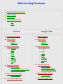
1
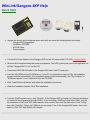
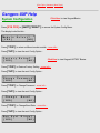
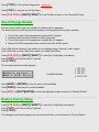
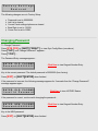
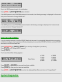
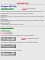
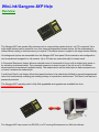
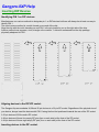
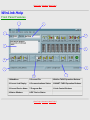
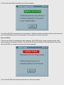
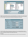
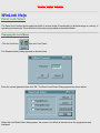
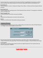
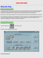
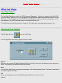
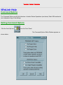
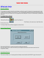
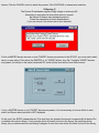
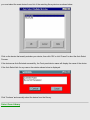
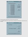
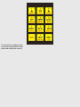
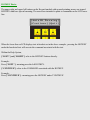
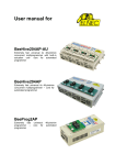
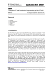
WinLink Help Contents
●
●
●
●
System Requirements
Quick Start
Overview
Inserting Devices
❍
DIP
❍
PLCC
WinLink
Gangpro-8XP
●
Front Panel Features
●
Panel Features
●
Device Select
●
Device Select
❍
❍
●
Device Operations
❍
❍
❍
❍
❍
❍
❍
❍
❍
●
❍
❍
●
❍
●
❍
❍
❍
❍
❍
❍
❍
❍
●
❍
❍
Test Device Sign Select
●
Setting Options
Copy Operation Options
Univ Compatibility Options
Device Features Select
❍
Setting Features
Program
Verify
Read
Erase
Blank
Copy
Compare
Features
Sign
Command Options
❍
●
Library
Auto-Select
Device Operations
❍
Setting Options
Program/Copy Operation Options
Univ Compatibilty Options
Device Features Select
❍
❍
Program
Verify
Read
Erase
Blank
Copy
Compare
Features
Sign
Command Options
❍
●
Library
Auto-Select
Setting Features
Test Device Sign Select
❍
●
Command Select (RUN)
❍
●
❍
●
❍
●
❍
❍
❍
●
Select/Change Device Module
●
System Configuration
❍
File Operations
❍
❍
Load
Save
❍
❍
❍
❍
●
Edit Buffer
❍
❍
❍
❍
❍
●
Viewing Lock Status
Engaging Lock
Disengaging Lock
Module Select
❍
●
Selecting Jobs
Managing Jobs
Front Panel Lock
❍
Change Lock Mode
Change Password
Changing Commands
Job List Manager
❍
●
Changing Test Sign..
Command Select (RUN)
❍
Selecting Jobs
Managing Jobs
Front Panel Lock
❍
●
Changing Commands
Job List Manager
❍
❍
Changing Test Sign..
Goto Address
Fill Buffer
Swap Bytes
Swap Words
Buffer Sign
Updating GP-8XP Code
❍
❍
Update
Recover
Sectect/Change Module
Restore Factory Settings
Changing Password
Setting Baud Rate
System Diagnostics
Winlink/Gangpro-8XP Help
System Requirements
●
Pentium based PC(100Mhz+) or equivalent.
●
Microsoft Windows 95/98/ME/NT/2K/XP
●
Mouse or other pointing device.
●
800x600 (or higher) video display
●
10 Mbytes free disk space.
●
32 Mbytes RAM (64M+ recommended).
●
free DB-9 RS-232 port (COM 1-4)
●
CD-ROM drive.
WinLink/Gangpro-8XP Help
Quick Start
●
●
●
●
●
Unpack the items from the shipping carton and verify you have the following items (as shown):
❍ Gangpro-8XP programmer
❍ Installation CD-ROM
❍ RS-232 Cable
❍ Power Adapter
Connect the Power Adapter to the Gangpro-8XP and an AC power outlet (115-VAC). Location Detail
Observe the front panel during the power up sequence. The LEDs (yellow) will cycle to the right and you
will see "Gangpro-8XP V1.xx" on the LCD.
Connect the DB-9 RS-232 cable to the Gangpro-8XP and a free PC serial port.
Insert the CD-ROM into the CD-ROM drive. If your PC is configured to auto-run CDs, the installation
program will start momentarily. If the installation does not start automatically, use "My Computer" or
"Windows Explorer" to run "install.exe" from the CD-ROM.
●
Click "Install WinLink Software" and follow the installation instructions.
●
When the installation finishes, Click "Exit Installation.
●
From the Start/Programs menu, click "WinLink". If the Gangpro-8XP is powered on, WinLink will attempt
to connect to the programmer through COM-1. If you are using a COM port other than COM-1, wait for
the connection to fail, click "NO" when asked to retry connect, then from the main menu, click "Config",
then click "ComPort". Select the COM port you are using. Turn off the Gangpro-8XP power, then turn it
back on. Click "OK" and WinLink will connect.
| Prev Topic | Contents | Next Topic |
Gangpro-8XP Help
Front/Back Panel Features
1-Keypad
5-TARGET ZIF Socket(1 of 8)
2-LCD Display
6-Power Jack
3-LED (1 0f 9)
7-RS-232 Connector
4-MASTER ZIF Socket
8-Code Update Switch
| Prev Topic | Contents | Next Topic |
| Prev Topic | Contents | Next Topic |
Gangpro-8XP Help
System Configuration
Click Here to view Keypad Basics
Press [SYS CFG] or [SHIFT][^RIGHT^] to access the System Config Menu.
The display looks like this...
Mo d u l e
[ YES ]
Se l e c t ?
[ NO ]
Press [^YES^] to select a different socket module ...more info...
Press [^NO^] to view the next Config Option...
F a c t o r y
[ YES ]
Se t up?
[ NO ]
Click Here to view Keypad HOTKEY Basics.
Press [^YES^] to Restore Factory Setting ...more info...
Press [^NO^] to view the next Config Option...
Ch a ng e
[ YES ]
Pa s swo r d?
[ NO ]
Press [^YES^] to Change Password ...more info...
Press [^NO^] to view the next Config Option...
Ch a ng e
[ YES ]
Ba ud?
[ NO ]
Press [^YES^] to Change Baud Rate ...more info...
Press [^NO^] to view the next Config Option...
Run Sy s t
[ YES ]
D i a g s ?
[ NO ]
Press [^YES^] to Run System Diagnostics ...more info...
Press [^NO^] to view the first Config Option...
Press [SYS CFG] or [SHIFT][^RIGHT^] to exit Config and return to the Command Prompt.
Select/Change Module
Several socket module types are available for different device packages.
The exact module you are using must be selected on the programmer for proper operation.
●
●
●
●
Turn off the power to the programmer (unplug the AC adapter).
Carefully install the desired module on the programmer.
Turn on the power to the programmer. (connect the AC adapter)
Observe the LEDs sequence yellow one at a time, then all blink green.
If the LEDs behave differently, the module is not installed properly. Remove it and try again.
If the LEDs flash correctly, select the module you installed as follows:
Press [SYS CFG] or [SHIFT][^RIGHT^] to view Syst Config Menu.(see above)
Press [^NO^] until 'Module Select?' appears...
Press [^YES^]....
The currently selected module appears...
●
Mo d u l e s e l e c t
Mo d = D I P 3 2 - 9
●
Available Modules:
●
●
DIP 32-9
DIP 32-5
DIP 32-1
PLCC 32-9
Press [NEXT] or [ENTER] to view the next module available.
Press [PREV] to view previous module available.
Press [EXIT] or [SHIFT][ENTER] to select the displayed module and return to 'Module Select?'
Restore Factory Setup
Press [SYS CFG] or [SHIFT][^RIGHT^] to view Syst Config Menu.(see above)
Press [^NO^] until 'Factory Setup?' appears...
Press [^YES^]....
The message shown below appears for several seconds then you are returned to 'Factory Setup?'.
F a c t o r y Se t t i ng s
Re s t o r e d
The following changes occur in Factory Setup:
●
●
●
●
●
Password is set to 00000000.
Job List is cleared
Current Panel settings/options are cleared
Baud Rate is set to 115200.
Comm Port is set to COM1.
Changing Password
To Change Password....
Press [SYS CFG] or [SHIFT][^RIGHT^] to view Syst Config Menu.(see above)
Press [^NO^] until 'Change Password?' appears...
Press [^YES^]....
The Password Entry message appears...
E N T E R O L D P A S SWD
Pa s sw r d = 0 0 0 0 0 0 0 0
Click Here to view Keypad Number Entry.
Key in the current password. The default password is 00000000 (from factory).
Press [EXIT] or [SHIFT][ENTER] when finished.
If the password is incorrect, the following message appears for 2 seconds then the 'Change Password?
message appears again:
E N T E R O L D P A S SWD
I n v a l i d Pa s swo r d
Click Here to view HOTKEY Basics.
If the password is correct, continue with changing the password...
E N T E R N EW P A S SWD
Pa s sw r d = 0 0 0 0 0 0 0 0
Key in the NEW password.
Press [EXIT] or [SHIFT][ENTER] when finished.
Click Here to view Keypad Number Entry.
CON F I RM
P A S SWD
Pa s sw r d = 0 0 0 0 0 0 0 0
Key in the NEW password again, for confirmation.
Press [EXIT] or [SHIFT][ENTER] when finished.
If the NEW password and CONFIRM password do not match, the following message is displayed for 2 seconds
and you are returned to 'Change Password?'.
CON F I RM
P A S SWD
PWD s D O N ' T M A T C H
If the NEW password and CONFIRM password match, the following message is displayed for 2 seconds and
you are returned to 'Change Password?'.
CON F I RM
P A S S WO R D
P A S SWD
CHANGED
Changing BaudRate
It is not normally necessary to set the GP-8XP baud rate because it is automatically detected when connecting
to WinLink. However, if you experience difficulty attempting to connect the GP-8XP to WinLink, set the GP-8XP
baud rate to the WinLink baud rate.
Press [SYS CFG] or [SHIFT][^RIGHT^] to view Syst Config Menu.(see above)
Press [^NO^] until 'Change Baud?' appears...
Press [^YES^]....
The Current Baud Rate Setting appears...
●
Mo d i f y Ba u d Ra t e
Ba ud Ra t e = 1 1 5 2 0 0
●
Baud Rates:
●
●
1200
2400
4800
9600
●
●
●
●
19200
38400
57600
115200
Press [NEXT] or [ENTER] to view next baud rate available.
Press [PREV] to view previous baud rate available.
Press [EXIT] or [SHIFT][ENTER] to select the displayed Baud Rate and return to 'Change Baud?'
System Diagnostics
The GP-8XP requires no internal calibration procedures.
The complete test requires electronic test equipment.
Only qualified technical personnel should perform these tests.
| Prev Topic | Contents | Next Topic |
| Prev Topic | Contents | Next Topic |
Gangpro-8XP Help
Lock Options Select
Click Here to view Keypad Basics
The Panel Lock Feature allows selective inhibit of various levels of functionality to facilitate usage in a variety of
operating environments. Three different lock modes are provided as described below.
Panel Edit Lock
Prevents editing Job contents, Configuration Settings. Device Select, Job Select and Device Operation Buttons
still active.
Panel Select Lock
Prevents selecting Jobs, selecting devices. Device Operation Buttons still active. The programmer is effectively
limited to a single device.
Panel Command Lock
All functions except Lock and Run command are inhibited.
Viewing Lock Status
To View the Lock Status....
On the KEYPAD, press
[LOCK] or [SHIFT][RUN] .
If the Front Panel is unlocked and no Lock Options are set...the display looks like this..
[ = LOCK
[ Op t s ]
MENU
= ]
Click Here to view Keypad HOTKEY Basics.
If the Front Panel is unlocked and one or more Lock Options are set...the display looks like this..
[ = LOCK
[ Op t s ]
MENU
= ]
[ Lo c k ]
If the Front Panel is locked...the display looks like this..
[ =
LOCK
MENU
= ]
[ UnLo c k ]
If no Lock Options are set, you cannot engage lock.
If lock is engaged, you cannot change Lock Options.
Press [EXIT] or [SHIFT][ENTER] to return to Command Prompt.
Changing Lock Options
To Change the Lock Option Setting and Engage the Lock....
Press [LOCK] or [SHIFT][RUN] .
Assume that no Options are set...the display looks like this...
[ = LOCK
[ Op t s ]
MENU
= ]
Click Here to view Keypad HOTKEY Basics.
Press [^Opts^] the display looks like this...
[ = LOCK OP T s
LOCK E d i t s
= = ]
= N
Click Here to view Keypad Menu Basics.
Press [ENTER] to set the Option... the display looks like this...
[ = LOCK OP T s
LOCK E d i t s
= = ]
= Y
Press [NEXT] to see the next Option... the display looks like this...
[ = LOCK OP T s
LOCK S e l e c t s
= = ]
= N
Press [ENTER] to set the Option... the display looks like this...
[ = LOCK OP T s
LOCK S e l e c t s
= = ]
= Y
Press [NEXT] to see the next Option... the display looks like this...
[ = LOCK OP T s = = ]
L O C K C o mm a n d s = N
Press [ENTER] to set the Option... the display looks like this...
[ = LOCK OP T s = = ]
L O C K C o mm a n d s = Y
Press [EXIT] or [SHIFT][ENTER] .
Since Options are now set, you have the ability to engage the lock, so the display looks like this
[ = LOCK
[ Op t s ]
MENU
= ]
[ Lo c k ]
Click Here to view Keypad HOTKEY Basics.
Press [^LOCK^]...the display looks like this...
E N T E R P A S S WO R D
Pa s sw r d = 0 0 0 0 0 0 0 0
Click Here to view Keypad Number Entry.
Using the Keypad, key in the current password. The default password is 00000000 (from factory).
Press [EXIT] or [SHIFT][ENTER] when finished.
If the password is incorrect, the following message appears for 2 seconds, then you are taken back to the point
before 'Enter Password'.
E N T E R P A S S WO R D
I n v a l i d Pa s swo r d
If the password is correct, the Panel is Locked and the following message appears for 2 seconds...
E N T E R P A S S WO R D
PANEL
i s LOCKED
The Lock Menu exits and the display reverts to the Command Prompt.
Disengaging Lock
To Disengage Panel Lock ....
Press [LOCK] or [SHIFT][RUN] .
Assume that the Panel id locked...the display looks like this...
[ = LOCK
[ Op t s ]
MENU
= ]
[ UnLo c k ]
Click Here to view Keypad HOTKEY Basics.
Press [^UnLock^]...the display looks like this...
E N T E R P A S S WO R D
Pa s sw r d = 0 0 0 0 0 0 0 0
Click Here to view Keypad Number Entry.
Using the Keypad, key in the current password. The default password is 00000000 (from factory).
Press [EXIT] or [SHIFT][ENTER] when finished.
If the password is incorrect, the following message appears for 2 seconds, then you are taken back to the point
before 'Enter Password'.
E N T E R P A S S WO R D
I n v a l i d Pa s swo r d
If the password is correct, the Panel is Locked and the following message appears for 2 seconds...
ENTER
PANEL
P A S S WO R D
UN LOCKED
The Lock Menu exits and the display reverts to the Command Prompt.
| Prev Topic | Contents | Next Topic |
| Prev Topic | Contents | Next Topic |
Gangpro-8XP Help
Job Manager
Click Here to view Keypad Basics
Use the Job Manager to:
●
●
●
●
Select an existing job
Create a new Job
Modify an existing Job
Delete an existing Job
Selecting Jobs
To Select a Job....
Press [JOB SEL]
The message shown below appears
[ = = J OB Me n u = = ]
[ Se l e c t ] [ Ma n a g e ]
Click Here to view HOTKEY Basics.
Press [^Select^]
The display now shows the first Job stored in the Job List which is Job[0000] containing part number Am27C64
(example Jobs shown...yours will differ).
[ = Se l e c t
J ob
[ 0 0 0 0 ] Am 2 7 C 6 4
= ]
Press [NEXT]To skip to the next Job in the Job list ....
The display now shows the second Job stored in the Job List which is Job[1111] containing part number
AT27C128
[ = Se l e c t
J ob = ]
[ 1 1 1 1 ] AT 2 7C1 2 8
Press [NEXT] or [PREV] to cycle through the Job List to find the desired Job.
Press [ENTER] to select the displayed Job.
Press [EXIT] or [SHIFT][ENTER]
to cancel Job Select.
Managing Jobs
To Delete a Job...
Press [JOB SEL]
The message shown below appears
[ = = J OB Me n u = = ]
[ Se l e c t ] [ Ma n a g e ]
Click Here to view HOTKEY Basics.
Press [^Manage^]
[ Mn g J o b ] = [ 0 0 0 0 ]
[ Ad d / Mo d ]
[ De l ]
Press [NEXT] to skip to the next Job in the Job list ....
The display now looks like this:
[ Mn g J o b ] = [ 1 1 1 1 ]
[ Ad d / Mo d ]
[ De l ]
Press [NEXT] or [PREV] to cycle through the Job List to find the desired Job.
Press[^DEL^] to delete the selected Job. You must confirm the deletion as shown below.
De l e t e
[ Ye s ]
J ob [ 1 1 1 1 ]
[ No ]
Press [YES] to delete the Job.
Press [NO] to skip deleting the Job.
In either case, you are returned to the '[Select][Manage]' display.
To Add or Modify a Job...
Press [JOB SEL]
The message shown below appears
[ = = J OB Me n u = = ]
[ Se l e c t ] [ Ma n a g e ]
Click Here to view HOTKEY Basics.
Press [^Manage^]
[ Mn g J o b ] = [ 0 0 0 0 ]
[ Ad d / Mo d ]
[ De l ]
Press [NEXT] to skip to the next Job in the Job list ....
The display now looks like this:
[ Mn g J o b ] = [ 1 1 1 1 ]
[ Ad d / Mo d ]
[ De l ]
Press [NEXT] or [PREV] to cycle through the Job List to find the desired Job.
Press [^ADD/MOD^] to create a new Job with the current Front Panel settings or modify an existing job.
The display now looks like this:
[ Ad d / Mo d i f y J o b ]
J OB NUM =
[ 1 1 1 1 ]
Click Here to view Keypad Number Entry.
The Job number defaults to the current job.
Press [EXIT] or [SHIFT][ENTER] to modify the job shown.
To create a new Job, or modify a different one, enter a new Job Number using the Keypad...
Press [EXIT] or [SHIFT][ENTER] .
If the Job Number Exists, the following appears:
J ob 1 1 1 1 Ex i s t s
[ Re p l a c e ]
[ Sk i p ]
Click Here to view HOTKEY Basics.
Press [^REPLACE^] to update the Job with the current Front Panel settings.
Press [^SKIP^] to skip the update.
If the Job Number does not exist, the Job is created with the current Front Panel settings and the following
message appears for 2 seconds.
[ Ad d / Mo d i f y J o b ]
J OB [ 1 2 3 4 ] C r e a t e d
If the Job List is full (25 jobs) the Job is NOT created and the following message appears for 2 seconds.
[ Ad d / Mo d i f y
J OB L i s t
i s
J ob ]
FULL
In either case, the message shown below appears
[ = = J OB Me n u = = ]
[ Se l e c t ] [ Ma n a g e
You can Select or Manage another job or
Press [EXIT] or [SHIFT][ENTER] to exit the Job Menu.
| Prev Topic | Contents | Next Topic |
| Prev Topic | Contents | Next Topic |
Gangpro-8XP Help
RUN Command Select
Click Here to view Keypad Basics
The RUN Command Sequencer stores a series of up to six commands that can later be executed by activating
a single button, either on the WinLink Front Panel, the GP-8XP Front Panel, or by an external switch. This
feature allows inexperienced users to perform complex programming tasks quickly and simply.
Each job has its own totally independent Command list that can be edited or executed when the job is selected.
The Command List is executed, one command at a time from left to right. If a command generates an error, the
sequence is stopped and the status of the failing command is displayed, otherwise the status of the last
command is displayed upon termination of the entire sequence.
Changing RUN Commands
To change the RUN Commands....
On the KEYPAD, press
[CMD SEL] or [SHIFT][JOB SEL]
Assuming the Command List is empty, the following message appears on the LCD:
CMD s |
[ C l r ]
[ De l ]
Note the cursor is at the first empty position.
To add a Command....
Use [NEXT] or [PREV] to move the cursor to the desired insert position,
then, press one or more of the following allowed commands:
[COPY]
[COMPARE]
[BLANK]
[FEAT PGM] or [SHIFT][COPY]
[SIGN DEV] or [SHIFT][COMPARE]
[ERASE] or [SHIFT][BLANK]
Assuming you pressed
[SIGN DEV] [ERASE] [BLANK]
The display now looks like this:
CMD s | S | E | B |
[ C l r ]
[ De l ]
Note that the letter shown on the display corresponding to the button pressed is underlined on the keypad.
To delete a Command....
Press [NEXT] or [PREV] to move the cursor to the desired command, then press the [^DEL^] HOTKEY.
Click Here for HOTKEY review.
To delete BLANK in this example, press...
[PREV], then press...
[^DEL^].
The display now looks like this:
CMD s | S | E |
[ C l r ]
[ De l ]
Now press...
[BLANK], [COPY]. [COMPARE].
The display now looks like this:
CMD s | S | E | B | C | M |
[ C l r ]
[ De l ]
To save the changes and exit, press..
[EXIT] or [SHIFT][ENTER]
This example would execute the following RUN Command Sequence when [RUN] is pressed.
TEST SIGN.. ERASE.. BLANK.. COPY.. COMPARE..
Note..you can clear the entire Command List by pressing the [^CLR^] HOTKEY.
| Prev Topic | Contents | Next Topic |
| Prev Topic | Contents | Next Topic |
Gangpro-8XP Help
Test Signature Select
Click Here to view Keypad Basics
The Test Signature is a number representing the MASTER device checksum that is stored in the CURRENT
Job. The Test Signature Button is used in the RUN Command Sequencer. Typically it is inserted as the first
RUN Command and its purpose is to calculate the Master Device Signature and compare it against the preset
Test Signature selected for the CURRENT Job. If the two signatures are the same, the RUN Command
Sequence continues with the next operation. If the signatures are different, the RUN Command Sequence
terminates with an error.
This feature provides an integrity check that the MASTER DEVICE is the correct one for the CURRENT Job.
Setting Test Signature
To change the Test Signature setting....
On the KEYPAD, press
[SIGN SEL] or [SHIFT][NEXT]
The following message appears:
Se l c t
S i gn En t r y
[ MANUA L ]
[ AUTO ]
Click Here to view HOTKEY Basics.
To enter the Test Sign using the KEYPAD, press...
[LEFT^]
To let the GP-8XP calculate the Test Sign from the currently inserted MASTER device, press...
[^RIGHT]
Manual Setting
Upon selecting the MANUAL entry mode, the following message appears:
ENTER TEST
N EW S I GN =
S I GN
1 2 3 4
Enter the New Test Signature using the Keypad.
Click Here to review Keypad Number Entry.
To save the entered number and exit, press...
Click Here to view Keypad Number Entry.
[EXIT] or [SHIFT][ENTER]
Auto Setting
Upon selecting the AUTO entry mode, the MASTER signature is calculated and during the Signature
Operation, the following message appears on the LCD:
[ 0 0 0 0 ] Am 2 9 F 0 0 4 T
S i gn a t u r • • •
When the calculation is completed, you are given the opportunity to edit and confirm the number as in Manual
Setting..
ENTER TEST
N EW S I GN =
S I GN
0 6 6 F
To save the entered number and exit, press...
[EXIT] or [SHIFT][ENTER]
| Prev Topic | Contents | Next Topic |
| Prev Topic | Contents | Next Topic |
Gangpro-8XP Help
Device Features Select
Click Here to view Keypad Basics
The term Device Features refers to programmable aspects of devices seperate from the actual memory array.
For EPROM/PROM family devices, there are no features. For FLASH family devices, this is typically some form
of write protection. Features Select allows setting of the available features for the CURRENT device. The
features setting is saved as part of the JOB. Note that Features Select only configures the desired device
features and the actual features programming is accomplished by the 'Feat..' button. Feature programming is
one of the available RUN Command Sequencer buttons.
The number of Device Features available is entirely device dependent. The Device Features are accessed thru
a rotating menu. Each feature setting is displayed one at a time on the LCD. You can cycle through them and
toggle the setting of the displayed feature.
Setting Device Features
For exemplary purposes, the AMD Am29F004T device is used below. This device has eleven sectors of
various sizes which can be individually protected from inadvertant programming.
To change the Device Feature settings....
On the KEYPAD, press
[FEAT SEL] or [SHIFT][PREV]
If the CURRENT DEVICE has no available features, the messge shown below appears...
[ NO DE V
P r e s s
FEAT s ! ! ]
[ ENTER ]
On the KEYPAD, press
[ENTER]
and Feature Select terminates.
If the CURRENT DEVICE has available features,
The first Device Feature (Sector Protect 64K BLK@00000h = enabled) is displayed as shown below.
P r o t e c t
Se c t o r
6 4 K B L K@ 0 0 0 0 0 h = Y
To disable Sector Protect for this block....
On the KEYPAD, press
Click Here to view Keypad Menu Basics.
[ENTER]
Now, the display looks like this:
P r o t e c t
Se c t o r
6 4 K B L K@ 0 0 0 0 0 h = N
To access the next Device Feature....
On the KEYPAD, press
[NEXT]
Now, the display looks like this:
P r o t e c t
Se c t o r
6 4 K B L K@ 1 0 0 0 0 h = N
To disable Sector Protect for this block....
On the KEYPAD, press
[ENTER]
Now, the display looks like this:
P r o t e c t
Se c t o r
6 4 K B L K@ 2 0 0 0 0 h = N
You can continue to cycle through all available options by pressing...
[NEXT] or [PREV]
You can change the setting of each by pressing...
[ENTER]
When finished setting the desired Device Features, press...
[EXIT] or [SHIFT][ENTER]
to save your changes and quit Feature Select
Remember that to actually PROGRAM the features you have selected, you must use the
[FEAT PGM] or [SHIFT][COPY] button.
| Prev Topic | Contents | Next Topic |
| Prev Topic | Contents | Next Topic |
Gangpro-8XP Help
Command Options
Click Here to view Keypad Basics
The five Command Options are accessed thru a rotating menu. Each option setting is displayed one at a time
on the LCD. You can cycle through them and toggle the setting of the displayed option.
Setting Command Options
To change the Command Option settings....
On the KEYPAD, press
[CMD OPT] or [SHIFT][LEFT^]
The first Command Option (Pre-Pgm Erase = enabled) is displayed as shown below.
[ = = = CMD
P r e - P gm
OP T s = = = ]
E r a s e =Y
To disable Pre-Pgm Erase....
On the KEYPAD, press
[ENTER]
Now, the display looks like this:
[ = = = CMD
P r e - P gm
OP T s = = = ]
E r a s e =N
To display the next Command Option...
On the KEYPAD, press
[NEXT]
The display shows the next option:
[ = = = CMD
P r e - P gm
OP T s = = = ]
B l a n k =Y
To display the next Command Option...
On the KEYPAD, press
[NEXT]
Click Here to view Keypad Menu Basics.
The display shows the next option:
[ = = = CMD OP T s = = = ]
P o s t - P gm T e s t
=Y
To display the next Command Option...
On the KEYPAD, press
[NEXT]
The display shows the next option:
[ = = = CMD OP T s = = = ]
Ma s t C omp a t i b = X
Note that =X indicates this option is not available for the CURRENT DEVICE.
To display the next Command Option...
On the KEYPAD, press
[NEXT]
The display shows the next option:
[ = = = CMD OP T s = = = ]
T a r g C omp a t i b = X
To display the previous Command Option...
On the KEYPAD, press
[PREV]
The display shows the previous option:
[ = = = CMD OP T s = = = ]
Ma s t C omp a t i b = X
To save the current settings and exit...
On the KEYPAD, press
[EXIT] or [SHIFT][ENTER]
COPY Options
These options modify the behaviour of the COPY button only. The options are ignored if COPY is performed
within the RUN command.
Most manufacturers deliver new parts pre-erased (blank). If new parts are programmed, it is not necessary to
pre-erase or pre-blank the parts thus saving considerable time. If previously programmed parts are being reprogrammed, it is suggested that they be pre-erased (if supported) and always pre-blanked.
Pre-Program Blank
If enabled, performs a TARGET device blank check prior to performing the COPY operation. If no TARGET
devices are blank, the COPY operation stops after the blank check.
Post-Program Verify
If enabled, performs a TARGET device COMPARE check after performing the COPY operation. Most
manufacturer's device programming algorithms include a post program verify requirement so it is suggested
that this option be always enabled. Only after successfully programming many devices with yield approaching
100%, should skipping the Post-Program verify be considered.
Pre-Program Erase
If the CURRENT DEVICE does not support the erase operation, this option will be ignored in the COPY
operation. If enabled, performs a TARGET device ERASE operation prior to performing the BLANK or
PROGRAM/COPY operation. Since some devices do not inherently indicate ERASE success, it is suggested
that Pre-Program Blank be performed in conjunction with Pre-Program Erase.
UNIVERSAL Options
Test Master Read Compatibility
This option will be disabled if the CURRENT DEVICE does not support Device ID.
If this option is enabled, the read compatibility of the MASTER device is tested against the CURRENT DEVICE
by reading the device ID of the MASTER device before each device operation.
If the MASTER device is NOT read compatible, the operation will terminate and a message (shown below)
indicates the failure. This insures that an in-experienced user does not attempt to copy an incorrect MASTER
device.
Ma s t e r
P r e s s
I n c omp a t
[ ENTER ]
If this option is disabled, no test is performed.
Test Target Program Compatibility
This option will be disabled if the CURRENT DEVICE does not support Device ID.
If this option is enabled, the program compatibility of the TARGET device(s) is tested against the CURRENT
DEVICE by reading the device ID of all TARGET devices before each device operation.
If a TARGET device is NOT program compatible, the operation will terminate and a message window (shown
below)indicates the failure. The incompatible devices will be indicated by blinking RED LEDs and the
compatible devices as green LEDs. This feature insures that an in-experienced user does not attempt to copy
TARGET devices using an incorrect programming algorithm.
T a r g ( s )
P r e s s
I n c omp a t
[ ENTER ]
If this option is disabled, no test is performed.
| Prev Topic | Contents | Next Topic |
| Prev Topic | Contents | Next Topic |
Gangpro-8XP Help
Device Operations
Click Here to view Keypad Basics
The ERASE, and FEAT PGM Device Operations are not pertinent to all devices. Initiating one of these
operations on a device in which the operation is not available causes the following message to appear on the
LCD:
[ OPERAT
P r e s s
I NVAL I D ]
[ ENTER ]
On the KEYPAD, press
[ENTER]
to continue.
Pre-Operation Test
Upon initiation of any Device Operation, a test is performed on each ZIF socket to determine if it is occupied by
a properly inserted device. Some operations require only MASTER or TARGET device, and some require both.
If a device is missing for a specific operation, no device is selected, or the device is not inserted properly, the
following message appears on the LCD:
ERROR ME S SAGE
P r e s s
[ ENTER ]
where ERROR MESSAGE is
●
●
●
●
●
●
●
No Master Device
No Target Dev(s)
No Device Sel'ed
Mast Incompat
Targ(s) Incompat
No Devices
Device Bus Error
On the KEYPAD, press
[ENTER]
to continue.
If it is possible to determine which device(s) are causing the fault, the LEDs will blink RED for the offending
device(s).
Intra-Operation Status
During the operation, valid devices are indicated by YELLOW LEDs and for most operations the LCD will
display a progress bar indicating the percentage of the opeartion completed. During all the Device Operations,
the LCD will display the CURRENT JOB number and CURRENT DEVICE name on the first line. Job [0000] and
Am29F004T are used below as examples.
Post-Operation Status
Upon termination of any Device Operation, failing devices are indicated by blinking RED LEDs and passing
devices are indicated by GRN LEDs. The LCD display shows the following:
[ OP ERA T I ON
DONE ]
P r e s s
[ ENTER ]
where OPERATION is
●
●
●
●
●
ERASE
BLANK
COPY
COMPARE
FEAT PGM
Erase
Erase restores the entire device to the blank state.
To initiate the Erase operation...
On the KEYPAD, press
[ERASE] or [SHIFT][BLANK]
During Erase, the following message appears on the LCD:
[ 0 0 0 0 ] Am 2 9 F 0 0 4 T
E r a s i ng
Blank
Blank Check compares each location in the device with the blank state.
To initiate the Blank operation...
On the KEYPAD, press
[BLANK]
During Blank Check, the following message appears on the LCD:
[ 0 0 0 0 ] Am 2 9 F 0 0 4 T
B l a n k
• • • • •
Copy
Copy programs the content of the MASTER device into the TARGET device(s).
To initiate the Copy operation...
On the KEYPAD, press
[COPY]
During Copy, the following message appears on the LCD:
[ 0 0 0 0 ] Am 2 9 F 0 0 4 T
Cop y i ng • • • •
Note: The Copy Operation behaviour is modified by the current Command Options
Compare
Compare tests each location in the MASTER device against the corresponding location in the TARGET
device(s).
To initiate the Compare operation...
On the KEYPAD, press
[COMPARE]
During Compare, the following message appears on the LCD:
[ 0 0 0 0 ] Am 2 9 F 0 0 4 T
C omp a r e
• • • •
Sign Dev
Sign Dev calculates the checksum of the MASTER or TARGET device by adding up the 8-bit values of all
locations in the device.
To initiate the Signature Operation...
On the KEYPAD, press
[SIGN DEV] or [SHIFT][COMPARE]
If both a MASTER and one or more TARGETs are inserted, you must choose to calculate the signature of
either the MASTER or the 1st TARGET device, so the following message appears:
[ Se l e c t
Sou r c e ]
[ Ma s t ] [ 1 s t
T a r g ]
Click Here to review HOTKEY usage.
On the KEYPAD, press the
[MAST] or [1st TARG]
During the Signature Operation, the following message appears on the LCD:
[ 0 0 0 0 ] Am 2 9 F 0 0 4 T
S i gn a t u r • • •
Upon Completion of the Signature Operation, the result is displayed as follows:
???????? = 0 1 2 3 4 5 6
P r e s s
[ ENTER ]
where ???????? is
●
●
MastSign
TargSign
depending of the selected signature source.
Feat Pgm
Feature Program sets security fuses or other device options.
If the CURRENT device has no available features or no features are selected, this operation has no effect.
To initiate the Feature Program operation...
On the KEYPAD, press
[FEAT PGM] or [SHIFT][COPY]
During Feature Programming, the following message appears on the LCD:
[ 0 0 0 0 ] Am 2 9 F 0 0 4 T
F e a t P gm ' i n g
Note: The Feature Program Operation behaviour is determined by the current Feature Selection
| Prev Topic | Contents | Next Topic |
| Prev Topic | Contents | Next Topic |
Gangpro-8XP Help
Device Select
Click Here to view Keypad Basics
The programmer needs to know the manufacturer and device name for the device to be programmed in order
to apply the correct signals to the device pins. This is accomplished manually by picking the manufacturer and
device from library lists in the programmer or automatically by reading the device ID.
Auto Select
!!! WARNING !!!
The Device ID mechanism applies a high voltage to device pin A9.
Attempting to auto-select a device that does not support
the device ID feature may damage the device.
Check the manufacturer device datasheet to insure the device supports the hardware ID feature.
To auto select a device, Press [AUTO ID] or [SHIFT][DEV SEL] .
The following WARNING message appears on the LCD to remind you of possible damage (see above):
A u t o - S e l Wa r n i n g
[ Con t i nu e ] [ Qu i t ]
Press [^CONTINUE^] to proceed with Auto Select...or
Press [^QUIT^] to exit.
If both a MASTER and one or more TARGETs are inserted, the following message appears:
[ Se l e c t
Sou r c e ]
[ Ma s t ] [ 1 s t
T a r g ]
Click Here to view HOTKEY Basics.
Press [^MAST^] to Auto Select the MASTER device.
Press [^1st TARG^] to Auto Select the first TARGET device.
At this point, the JEDEC standard device ID is read from the selected device and compared with all device IDs
contained in the device library. If only a single device ID match is found in the library, the matching device
library entry is selected and the next dialog is skipped. If more than one device ID match is found in the library,
you must select the exact device from a list of the matching library devices. The list appears one device at a
time as shown below.
[ Se l e c t De v i c e
MX 2 7 C 2 5 6
]
Press [NEXT] or [PREV] to step through the list until an exact match with your device is displayed.
In this example, the next device in the list would be displayed as shown below.
[ Se l e c t De v i c e
MX 2 7 L 2 5 6
]
Press [ENTER] to Select the displayed device.
Press [EXIT] or [SHIFT][ENTER] to cancel the Auto Select process.
If the DEVICE Auto Select is successful, the DEVICE name and CURRENT JOB appear as shown below and
the programmer is ready for another command
[ 0 0 0 0 ] MX 2 7 L 2 5 6
If the DEVICE Auto Select is not able to find the device ID in the library, the following message appears on the
LCD.
De v i c e
P r e s s
no t
Found
[ ENTER ]
Press [ENTER] to continue without any change in DEVICE selection.
Select from Library
On the KEYPAD, press
[DEV SEL]
The first MANF from the library is displayed on the LCD.
[ = Se l e c t
AMD
M f r
= ]
On the KEYPAD, press
[NEXT] or [PREV]
to scroll through the MANF list until the desired MANF is displayed.
On the KEYPAD, press
[ENTER]
to select the displayed MANF.
The first device name in the DEVICE library for the selected MANF is displayed on the LCD
[ = Se l e c t
Am 2 7 C 6 4
De v
= ]
On the KEYPAD, press
[NEXT] or [PREV]
to scroll through the DEVICE list until the desired DEVICE is displayed.
On the KEYPAD, press
[ENTER]
to select the displayed DEVICE.
The programmer is now configured for the selected DEVICE.
| Prev Topic | Contents | Next Topic |
WinLink/Gangpro-8XP Help
Overview
The Gangpro-8XP can operate fully autonomously to copy existing master devices...no PC is required. Up to
eight target devices can be copied at once from one pre-programmed master device. No file downloading or
master device loading to internal memory is required. The master device is copied to the target devices directly.
All settings and options are accessible from the Gangpro-8XP front panel. Device selection and configuration
can be saved and assigned to a Job number. Up to 25 Jobs can saved internally for instant recall.
A Command Sequencer feature allows a selected series of commands to be run with a single button press or
by activating an external switch. The command sequence is stored as part of the Job so up to 25 different
sequences can be saved and recalled instantly. The master device can be tested prior to each sequencer run
to insure it matches the selected job.
A multi-level Panel Lock feature allows front panel functions to be selectively inhibited to prevent inexperienced
users from inadvertently modifying pre-existing settings in a production environment. The Panel Lock feature is
password protected.
The Gangpro-8XP operating code is fully field upgradable and upgrades are available free from
www.logicaldevices.com
The Gangpro-8XP can connect via RS-232, to a PC running Windows and our WinLink software.
WinLink provides a graphical control interface to the Gangpro-8XP front panel. All Gangpro-8XP settings and
options are accessible from WinLink. Additionally, WinLink allows programming of target devices from a PC file.
Standard file formats are automaticlly recognized during reading. File record offsets for typical situations can be
automatically scanned from the file.
WinLink provides a data edit buffer as a source and destination for file read and save operations. Device data
can be read into the buffer and then saved to a file. Files can be read into the buffer and programmed into
devices. Data in the buffer can be edited at any time in either hex or ascii formats. Both bytes and words can be
swapped in the buffer to accomodate big/little endian target systems.
WinLink and the Gangpro-8XP auto-negotiate RS-232 settings to facilitate establishing a connection and
communication occurs through a packet based protocol for data transfer reliabilty.
Gangpro-8XP Help
Inserting DIP Devices
Identifying PIN 1 on DIP devices.
Manufacturers use various methods to designate pin 1 on DIP devices but there will always be at least one way to
identify PIN 1.
The most common method is a notch formed on one end of the chip.
Align the chip with the notch towards you and PIN 1 is the pin closest to you on the right side of the chip.
Another method uses a square, circle, triangle or the number '1' etched or embossed into the chip package
physically adajacent to PIN 1.
Aligning devices in the DIP ZIF socket.
The Gangpro-8xp accomodates 24,28 and 32 pin devices in a 32 pin ZIF socket. Regardless of the physical size of
your device, always insert the devices with PIN 1 facing the front but positioned towards the rear of the ZIF socket.
A 32 pin device will fill the entire ZIF socket.
A 28 pin device will leave four empty ZIF pins (two on each side) at the front of the ZIF socket.
A 24 pin device will leave eight empty ZIF pins (four on each side) at the front of the ZIF socket.
Inserting devices in the ZIF socket.
●
●
●
Open the ZIF socket by moving the small metal handle to the vertical position.
Insert the device observing the proper alignment described above.
Close the ZIF socket by moving the handle to the horizontal position.
Inserting PLCC Devices
Identifying PIN 1 on PLCC devices.
Two types of PLCC ZIF sockets are common.
'Live bug' types accept devices right side up. (logo and device number on top)
'Dead bug' types accept devices upside down. (logo and device number on bottom)
PLCC devices always have one flat corner.
If you align the device with the flat corner in the upper left. Pin 1 is on the top edge.
Additionally, pin 1 is usually identified by a circular dimple in the package material located next to pin 1.
Aligning devices in the PLCC ZIF socket.
The Gangpro-8xp PLCC 32-9 module uses 'live bug' sockets.
Match the flat corner of the device (right side up) with the flat corner of the PLCC socket.
Place the device gently in the socket.
Press down on the device with your finger so the outer shell of the socket moves upward.
The device should not be skewed and should be positioned flatly.
To remove the device, press the outer shell of the socket down quickly and the chip will pop out.
| Prev Topic | Contents | Next Topic |
WinLink Help
Front Panel Features
1-MainMenu
5-Current File
9-Buffer-TARG Operation Buttons
2-Current Job Display
6-Communications Status
10-MAST-TARG Operation Buttons
3-Current Device Name
7-Progress Bar
11-Job Control Buttons
4-Status Window
8-ZIF Device Status
| Prev Topic | Contents | Next Topic |
| Prev Topic | Contents | Next Topic |
WinLink Help
Update Programmer Code
The GP-8XP contains operating code in FLASH memory that allows it to communicate with WinLink as well as
operate autonomously. Periodically, Logical Devices provides updates to this code that enhances functionality,
supports additional devices and fixes known bugs. WinLink provides a mechanism to re-program the FLASH
memory inside the GP-8XP. There are actually two re-programming modes, one of which becomes active
automatically depending on the state of the GP-8XP FLASH code. If the GP-8XP is functioning normally where
it can communicate with WinLink, the Update Mode is used. If the GP-8XP FLASH code is corrupted for some
reason (such as a failed update attempt), the Recover mode is used.
Update Mode (GP-8XP working properly)
From the Front Panel Main Menu, click 'Config', then click 'Update Programmer Code' and the dialog shown
below appears.
Click the 'Start' button to initiate the update process whereby the file open dialog shown below appears, or
'Cancel' to abandon the process and close the window.
Select the .UPD file that will be used for the update. Click 'Open'. The update process begins and the ongoing
update status is displayed in the status window and by the completion bar as shown below.
Memory Blocks 0 to 4 are erased before programming begins. The status of each step is displayed in the status
window. The entire process takesabout 3 minutes.
Update Success
If the update succeeded, the dialog shown below appears.
Turn off the GP-8XP as instructed, then turn it back on. Watch the display and make sure the version shown on
the LCD matches the version of the update file. This completes the update process.
Update Failure
If the update failed, the dialog shown below appears. The GP-8XP will no longer function normally, either
autonomously or connected to Winlink. Turn off the GP-8XP and exit WinLink. Note that WinLink may sense
that the GP-8XP is no longer functioning and exit automatically.
Turn off the GP-8XP and follow the instructions below for 'Recover'.
Recover Mode (GP-8XP NOT working properly)
Unplug the GP-8XP power adapter and Start Winlink. Winlink will sense that no programmer is connected and
respond with the following:
'Retry Connection?'.....Click 'No'.
'Exit Winlink?'.........Click 'No'.
From the Front Panel Main Menu, click 'Config', then click 'Update GP-8XP Code' and the dialog shown below
appears.
Click the 'Start' button to initiate the recovery process and the file open dialog shown below appears, or click
'Cancel' to abandon the process and close the window.
Select the .UPD file that will be used for the update. Click 'Open'. Winlink senses that the GP-8XP is inoperable
and displays the dialog shown below.
Follow the instructions shown in the dialog. DO NOT click continue until you have completed the GP-8XP
recovery power on steps. It is important that you press the rear panel code switch until the LEDs light. When
the LEDs are on, click 'Continue' and the dialog shown below appears.
Recover Success
If the recovery succeeded, the dialog shown below appears.
Turn off the GP-8XP as instructed, then turn it back on. Watch the display and make sure the version shown on
the LCD matches the version of the update file. This completes the recovery process.
Recover Failure
If the recovery failed, the dialog shown below appears. The GP-8XP will no longer function normally, either
autonomously or connected to Winlink. Turn off the GP-8XP and exit WinLink. Note that WinLink may sense
that the GP-8XP is no longer functioning and exit automatically.
Turn off the GP-8XP and repeat the instructions for 'Recover' carefully.
| Prev Topic | Contents | Next Topic |
| Prev Topic | Contents | Next Topic |
WinLink Help
Data Buffer Editor
The contents of the Edit Buffer are displayed in HEX and ASCII. Use the scroll bar to navigate to the desired
page and click on the specific address to edit in either the HEX or ASCII panels, then type in your changes. The
Edit Buffer always starts at address 00000 and ends at the last address in the CURRENT DEVICE.
Goto Buffer Address
This button allows a jump to a random address in the Edit Buffer. Enter the desired address and click OK. The
specified address will be masked to a paragraph (16 byte) boundary. If the specified address is 1234h, the
page displayed will start at address 1230h.
Fill Buffer
This button fills an address range in the Edit Buffer with a specific value. Enter the Start and Stop Addresses
and the desired fill data and click OK.
Swap Bytes
This button swaps the position of bytes at even and odd addresses in the entire edit buffer.
example...
Before
After
00000 = 00 00000 = 11
00001 = 11 00001 = 00
00002 = 22 00002 = 33
00003 = 33 00003 = 22
This function is useful for programming memory devices intended for use with 'Big-Endian' microprocessors
such as the Motorola 68HC family.
Swap Words
This button swaps the position of words at even and odd addresses in the entire edit buffer.
example...
Before
After
00000 = 00 00000 = 22
00001 = 11 00001 = 33
00002 = 22 00002 = 00
00003 = 33 00003 = 11
This function is useful for programming memory devices intended for use with 'Big-Endian' 32 bit
microprocessors. Swap Words used in conjunction with Swap bytes can reverse the byte order of 32 bit words.
Buffer Sign
This button calculates and displays the signature (checksum) of the Edit Buffer for the address range of the
CURRENT DEVICE. It can be used to quickly determine a new signature after editing the buffer.
| Prev Topic | Contents | Next Topic |
| Prev Topic | Contents | Next Topic |
WinLink Help
File Operations
File Operations allow the loading of file data into the Data Edit Buffer or saving the Data Edit Buffer to a file.
Binary, Intel Hex, Motorola S, and Tektronix Hex file formats are supported. The specific file format is autodetected when the file is loaded. The current file name, format and load/save options are remembered so that
repeated load/save of the same file does not require re-entry of the pertinent information.
File Load
To load a file, click 'FILE' on the main menu, then click 'LOAD' from the drop down menu. The standard
Windows File Load dialog shown below appears.
Navigate to the desired folder and click on the appropriate filename to be loaded so that it is hi-lited, then click
'OPEN'. Note that if the file was previously opened, the default filename is already shown and it is necessary
only to click 'OPEN'. In either case the File Load Options Dialog appears as shown below.
The File Load Options Dialog controls placement of data from the file into the Data Edit Buffer as well as
selection of the format in which the file data is interpreted (bin, hex, etc.). If a file has previously been loaded,
the File Load parameters will default to the previously entered values.
File Format
One of the File Format buttons will be checked indicating the result of the File Format Auto-detect which
occurred when the file was opened. If this is not the proper file format for the selected file, click the button
corrsponding to the desired format.
From File Addr
The 'From File Addr' parameter instructs the loader software at which file address to begin loading file data into
the Data Edit Buffer.
Up to File Addr
The 'Up to File Addr' parameter instructs the loader software at which file address to stop loading file data into
the Data Edit Buffer.
To Buffer Addr
The 'To Buffer Addr' parameter instructs the loader software at which Data Edit Buffer address to begin storing
file data.
Reset Button
Click 'RESET' to force the default values which cause data from file address 00000000h to be loaded to Data
Edit Buffer address 00000000h up to the size of the CURRENT DEVICE.
Scan File Button
Click 'SCAN FILE' to automatically determine the lowest and highest addresses in the file and set the File Load
parameters according to a 'best guess' solution. This is useful when the file contains data at addresses beyond
the size of target device. For example, a PC boot EPROM typically resides at address E0000h in the PC
address space and the file to program this device may contain addresses at E0000h and beyond. However, the
data at E0000h in the file must be programmed into address 00000h in the device. The File Load parameters
could be set manually or set by the SCAN FILE button which would produce the following assuming a 512 Kbit
device:
From File Addr = E0000h
Up to File Addr = F0000h
To Buffer Addr = 00000h
If the Lowest File address found by 'SCAN FILE' is not a multiple of the device size, the 'From File Addr' is
adjusted downward to the next lowest multiple of the device size. For example, assume the lowest file address
is 12345h and the device size is 512K bits. 'SCAN FILE' returns the following:
From File Addr = 10000h
Up to File Addr = 20000h
To Buffer Addr = 00000h
The file data at 12345h would be placed in the Buffer at 2345h.
File Save
To load a file, click 'FILE' on the main menu, then click 'SAVE' from the drop down menu. The standard
Windows File Save dialog shown below appears.
Navigate to the desired folder and click on the appropriate filename to be loaded so that it is hi-lited, then click
'SAVE'. Note that if the file was previously opened, the default filename is already shown and it is necessary
only to click 'SAVE'. In either case the File Save Options Dialog appears as shown below.
The File Save Options Dialog controls placement of data from Data Edit Buffer in the file as well as selection of
the format in which the file is written(bin, hex, etc.). If a file has previously been saved, the File Save
parameters will default to the previously entered values.
File Format
Select the desired File Format in which to save the file.
From Buffer Addr
Specifies the Data Edit Buffer starting address from which data is saved to the file. By default, this address also
becomes the File address (see 'To File Addr', below) and each data byte saved increments this address.
Up to Buffer Addr
Specifies the Data Edit Buffer ending address where saving of buffer data stops.
To File Addr
Specifies the offset address which is added to each data record address that is written to the file.
Reset Button
Sets the File Save Parameters to their default values which saves data from Data Edit Buffer address
00000000h to the size of the CURRENT DEVICE to File address 00000000h.
Repro Load Button
This sets the File Save Parameters to values that will reproduce the file originally loaded using the File Load
parameters.
| Prev Topic | Contents | Next Topic |
| Prev Topic | Contents | Next Topic |
WinLink Help
Module Select
Module Select allows you to select (from WinLink) the exact module installed on the programmer.
The WinLink socket display will change to match the selected module.
When Winlink starts, it always reads the installed module type from the programmer but when you change the
module, you must select the new module either from the programmer keypad or from Winlink. Once the new
module is selected by either method, the programmer will remember the module selection and WinLink will
display the proper socket layout.
Selecting the Module...
Click 'Config' on the Front Panel main menu bar.
Click 'Select Device Module' on the drop down menu.
The Module Select Window appears as shown below...
Click the desired module in the list.
Click 'OK'.
You can also double click the list item.
Click 'Cancel' to abort the selection process.
| Prev Topic | Contents | Next Topic |
WinLink Help
Panel Lock Select
The Panel Lock Feature allows selective inhibit of various levels of functionality to facilitate usage in a variety of
operating environments. Three different lock modes are provided as described below.
Changing the Lock Mode
Click the Lock icon
from the Front Panel
The Password entry dialog appears as shown below.
Enter the current password and click 'OK'. The Panel Lock Select Dialog appears as shown below.
When the Lock Mode Select dilaog opens, the current Lock Mode is retrieved from the programmer and
displayed.
Check/uncheck the box associated with the desired Lock Mode to enable/disable that particular Lock Mode.
Buttons and Menu Items become grayed out and therefore inaccessible when they are inhibited by Lock.
Panel Edit Lock
Prevents editing Job contents, Configuration Settings. Device Select, Job Select and Device Operation Buttons
still active.
Panel Select Lock
Prevents selecting Jobs, selecting devices. Device Operation Buttons still active. The programmer is effectively
limited to a single device.
Panel Command Lock
All functions except Lock and Run command are inhibited.
OK
Updates the Lock Mode based on the state of the check boxes.
Cancel
Closes the Lock Mode Select dialog without making any changes.
Changing the Password
To change the current password, get to the Lock Select dialog as described above, then click 'New Password'.
The Change Password dialog appears as shown below.
Enter the desired password in the 'New Password' box, press 'Enter', then re-enter the password in the
'Confirm Password' box, then press 'Enter'. Click 'OK' to make the change, or 'Cancel' to abandon the change.
Lost Password
In the event, you forget the current password, perform an 'Update Programmer Code' operation which will
default the password to '00000000'.
| Prev Topic | Contents | Next Topic |
| Prev Topic | Contents | Next Topic |
WinLink Help
Job List Manager
The Job List Manager allows manipulation of the job list contained in the GP-8XP. The Job List can be read
from or written to the GP-8XP and be saved to or loaded from a disk file. Up to 25 seperate jobs can be stored
internally in the GP-8XP in a single Job List.
Each job contains all the selections and options available on the WinLink front panel and can be saved and
recalled instantly. Jobs are identified by a 4 digit numeric tag that the user assigns when the job is created. The
user is prompted to save changes made to the currently selected job if another job is selected. An exception to
this is when the currently selected job is #0000. Changes made in this case are saved automatically. Job #0000
cannot be created or removed and a Job #0000 is created automatically in every new Job List.
Managing the Job List
Click the Job Sel icon
from the Front Panel
The Job List Manager Window appears as shown
below...
Job List Functions
New List
This button clears the GP-8XP internal Job List (leaving job #0000 intact) and sets the Job List Name to 'no
name'.
Clear List
This button clears the GP-8XP internal Job List (leaving job #0000 intact) but does not alter the Job List Name.
Write List
This button writes the contents of the Job List Window to the GP-8XP internal memory.
Read List
This button reads the contents of the GP-8XP internal memory into the Job List Window.
Select Job
This button selects the highlighted job in the Job List Window on the GP-8XP.
If the current job is NOT Job #0000 and changes have been made in the Front Panel settings, the user is asked
if the changes should be saved and if so to which job.
Add/Modify Job
This button allows the user to update an existing job with the current Front panel settings or create a new job
containing the current Front Panel settings.
Remove Job
This button deletes the highlighted job from the GP-8XP internal memory and Job List Window.
Move Up
This button moves the highlighted job up one position in the Job List Window.
Move Down
This button moves the highlighted job down one position in the Job List Window.
| Prev Topic | Contents | Next Topic |
| Prev Topic | Contents | Next Topic |
WinLink Help
RUN Command Select
The RUN Command Sequencer stores a series of up to six commands that can later be executed by activating
a single button, either on the WinLink Front Panel, the GP-8XP Front Panel, or by an external switch. This
feature allows inexperienced users to perform complex programming tasks quickly and simply.
Each job has its own totally independent Command list that can be edited or executed when the job is selected.
The Command List is executed, one command at a time from left to right. If a command generates an error, the
sequence is stopped and the status of the failing command is displayed, otherwise the status of the last
command is displayed upon termination of the entire sequence.
Changing RUN Commands
Click the Cmd Sel icon
from the Front Panel
The editor window appears as shown below
Current Command List
Displays the commands in the Current Command List. To Move or Delete a command in the Current Command
List, click the button so that it appears depressed, then click the desired action button.
Available Command List
Displays the commands available for the CURRENT DEVICE. Commands NOT available will be grayed-out
and therefore inaccessible. Click on any of the Available Command buttons to add it to the Current Command
List.
Move Left
Moves the currently selected Command Button left one position in the Current Command List.
Move Right
Moves the currently selected Command Button right one position in the Current Command List.
Delete
Deletes the currently selected Command Button in the Current Command List.
Delete All
Deletes the entire Current Command List.
OK
Saves the Current Command List in the GP-8XP Current Job.
Cancel
Cancels changes and closes the RUN Command Sequence Editor window.
| Prev Topic | Contents | Next Topic |
| Prev Topic | Contents | Next Topic |
WinLink Help
Test Sign Select
The Test Sign Operation is used in the RUN Command Sequencer. Typically it is inserted as the first RUN
Command and its' purpose is to check the Master Device Signature against the preset sign stored in the Job
Parameters. If the two signs agree, the RUN Command Sequence continues with the next operation. If the
signs disagree, the RUN Command Sequence terminates with an error.
Test Sign Select provides the means to change the Test Sign Value associated with a particular Job.
Changing the Test Signature
Click the Sign Sel icon
from the Front Panel
The Test Signature Editor dialog appears as shown below.
Manual
Make sure the value in the Master Signature Edit Box is hi-lited, then type in the desired number and press
'Enter'. Note that only hexadecimal values are allowed.
Auto
Click the 'Calc Sign' Button to calculate the signature of the Current Master Device. The value is inserted into
the 'Master Signature Edit Box'.
OK
Stores the Test Sign shown in the Master Signature Edit Box in the Current Job.
Cancel
Closes the window and cancels any changes.
| Prev Topic | Contents | Next Topic |
| Prev Topic | Contents | Next Topic |
WinLink Help
Command Options
The Command Options modify the behaviour of certain Device Operations (see below). Each JOB contains its
own indepenent copy of the settings.
Setting Command Options
Click the Cmd Opt icon
from the Front Panel
The Command Options Editor Window appears as
shown below...
Check/Uncheck the desired options.
Click 'OK' to save current settings.
Click 'Cancel' to abandon current settings.
PROGRAM/COPY Options
These options modify the behaviour of the PROGRAM and COPY buttons only. The options are ignored if
COPY is performed within the RUN command.
Most manufacturers deliver new parts pre-erased (blank). If new parts are programmed, it is not necessary to
pre-erase or pre-blank the parts thus saving considerable time. If previously programmed parts are being reprogrammed, it is suggested that they be pre-erased (if supported) and always pre-blanked.
Pre-Program Blank
If checked, performs a TARGET device blank check prior to performing the PROGRAM/COPY operation. If no
TARGET devices are blank, the PROGRAM/COPY operation stops after the blank check.
Post-Program Verify
If checked, performs a TARGET device VERIFY/COMPARE check after performing the PROGRAM/COPY
operation. Most manufacturer's device programming algorithms include a post program verify requirement so it
is suggested that this option be always checked. Only after successfully programming many devices with yield
approaching 100%, should skipping the Post-Program verify be considered.
Pre-Program Erase
If the CURRENT DEVICE does not support the erase operation, this option will be grayed out. If checked,
performs a TARGET device ERASE operation prior to performing the BLANK or PROGRAM/COPY operation.
Since some devices do not inherently indicate ERASE success, it is suggested that Pre-Program Blank be
performed in conjunction with Pre-Program Erase.
UNIVERSAL Compatibility Options
Test Master Read Compatibility
This option will be grayed out if the CURRENT DEVICE does not support Device ID.
If this option is checked, the read compatibility of the MASTER device is tested against the CURRENT DEVICE
by reading the device ID of the MASTER device before each device operation.
If the MASTER device is NOT read compatible, the operation will terminate and a message window (shown
below) indicates the failure. This insures that an in-experienced user does not attempt to copy an incorrect
MASTER device.
If this option is unchecked, no test is performed.
Test Target Program Compatibility
This option will be grayed out if the CURRENT DEVICE does not support Device ID.
If this option is checked, the program compatibility of the TARGET device(s) is tested against the CURRENT
DEVICE by reading the device ID of all TARGET devices before each device operation.
If a TARGET device is NOT program compatible, the operation will terminate and a message window (shown
below)indicates the failure. The incompatible devices will be indicated as red ZIFs and the compatible devices
as green ZIFs on the ZIF DISPLAY. This insures that an in-experienced user does not attempt to copy
TARGET devices using an incorrect programming algorithm.
If this option is unchecked, no test is performed.
| Prev Topic | Contents | Next Topic |
| Prev Topic | Contents | Next Topic |
WinLink Help
Device Operations
These operations perform some function on the MASTER device, TARGET device(s) or both. If the completion
time of the operation can be determined, then the progress bar indicates the progress of the operation. Before
each operation, the ZIF sockets are tested to determine if a device is present and correctly inserted. Also the
device(s) required for the operation is checked and will terminate if the necessary devices are not present. The
Command Options settings affect the behaviour of Device Operations. The Command Options can modify what
happens in the COPY/PROGRAM operation as well as controlling the READ and PROGRAM mode device
compatibilty tests.
Device Operation Buttons
Program
This button copies the contents of the Edit Buffer into the Target Devices.
The Progress bar indicates the progress of the operation.
Verify
This button compares the contents of the Edit Buffer with the Target Devices.
The Progress bar indicates the progress of the operation.
The Command Options affect the behaviour of the Copy Operation.
Read
This button reads either the Master Device or the 1st Target Device into the Edit Buffer.
The Progress bar indicates the progress of the operation.
Erase
This button (if available) erases the Target Device(s) to the blank state.
Blank
This button checks the Target Device(s) to determine if they are blank.
The Progress bar indicates the progress of the operation.
Copy
This button copies Master Device data into the Target Device(s).
The Progress bar indicates the progress of the operation.
Compare
This button compares Master Device data with the Target Device(s) data.
The Progress bar indicates the progress of the operation.
Features
This button (if available) programs the device features of the Target Device(s)
Sign
This button calculates either the Master Device or the 1st Target Device signature (chksum). The
Progress bar indicates the progress of the operation.
Device Operation Status
During an operation, and after termination, the status of each IC can be determined by the ZIF socket display
as indicated below. The colors used mimic the GP-8XP Front Panel Status LED colors.
Indicates ZIF socket is empty.
Indicates ZIF socket contains an IC, but it is not being used in the operation.
Indicates ZIF socket contains an IC and it is used in the operation, but the operation is not yet
complete.
Indicates ZIF socket contains an IC and it passed the operation.
Indicates ZIF socket contains an IC and it failed the operation.
| Prev Topic | Contents | Next Topic |
| Prev Topic | Contents | Next Topic |
WinLink Help
Device Select
The programmer needs to know the manufacturer and device name for the device to be programmed in order
to apply the correct signals to the device pins. This is accomplished manually by picking the manufacturer and
device from library lists obtained from the programmer and displayed in WinLink or automatically by reading the
device ID.
To Initiate Device Select
Click the Dev Sel icon
from the Front Panel or....
Click Device on the main menu, then Select from
the drop down menu....
The Device Select Source Window appears as shown below.
Device Select Source
Click the AutoSel button to select the device by reading the device ID.
Click the Library button to select the device by choosing the manufacturer and device name from the
Programmer Library
Auto-Select Device
Click the Auto-Select Icon. A warning window indicates device families that DO NOT support the device ID
feature. Click the CANCEL button to abort the process. Click CONTINUE to attempt auto-selection.
!!! Warning !!!
The Device ID mechanism applies a high voltage to device pin A9.
Attempting to auto-select a device that does not support
the device ID feature may damage the device.
Check the manufacturer device specifications
if you are unsure if the device can be auto selected.
If both a MASTER device and one or more TARGET devices are present in the GP-8XP, you must select which
device to auto-select. Click either the MASTER or 1st TARGET button, then OK. If multiple TARGET devices
are present, the device in the lowest numbered ZIF socket will be used as the Auto-Select source.
If only a MASTER device or only TARGET devices are present, it is not necessary to choose which to autoselect and Source select window is NOT displayed.
At this point, the JEDEC standard device ID is read from the selected device and compared with all device IDs
contained in the device library. If only a single device ID match is found in the library, the matching device
library entry is selected and the next dialog is skipped. If more than one device ID match is found in the library,
you must select the exact device from a list of the matching library devices as shown below.
Click on the device that exactly matches your device, then click 'OK' or click 'Cancel' to abort the Auto Select
Process.
If the device was Auto Selected successfully, the Front panel device name will display the name of the device.
If the Auto Select fails for any reason the window shown below is displayed.
Click 'Continue' and manually select the device from the Library.
Select from Library
When the Device Select Window is opened, the list of available device manufacturers is retrieved from the GP8XP and displayed in the listbox on the left. Click the desired manufacturer and the available devices for the
selected manufacturer is retrieved from the GP-8XP and displayed in the listbox on the right. Scroll down to find
the desired device, then click it. Click the OK button to select the device. Clicking the CANCEL button closes
the Device Select Window without changing the selected device.
| Prev Topic | Contents | Next Topic |
| Prev Topic | Contents | Next Topic |
WinLink Help
Device Features Select
The term features refers to programmable aspects of devices seperate from the actual memory array. For
EPROM/PROM family devices, there are no features. For FLASH family devices, this is typically some form of
write protection. Features Select allows setting of the available features for the CURRENT device. The features
setting is saved as part of the JOB. Note that Features Select only configures the desired device features and
the actual features programming is accomplished by the 'Feat..' button. Feature programming is one of the
available RUN Command Sequencer buttons.
Setting Device Features
Click the Feat Sel icon
from the Front Panel
If the CURRENT DEVICE has supported features, they are listed in the form of checkboxes in the manner
shown below.
Check the each box corresponding to the desired features and click 'OK'.
If the CURRENT DEVICE has no supported features, the dialog shown below appears. Click 'Cancel' to close
the dialog.
| Prev Topic | Contents | Next Topic |
To execute key captions in red,
Press and release [SHIFT],then
press and release the red key.
Menu Basics
Option menus are lists where each list element is composed of a text string (the name of the option) and an
associated boolean (Y/N) field which indicates the current option state (enabled/disabled).
Each option is displayed one at time like this:
option = Y/N
and the user can scroll forward and backward in the list and toggle the setting of the option using the Keypad.
OPTION MENU KEYS
[NEXT]-displays next option (wraps around)
[PREV]-displays previous option (wraps around)
[ENTER]-toggles the state of the option.
[EXIT]-exits and saves current option settings.
OPTION MENU STATUS
=Y-indicates option is enabled
=N-indicates option is disabled
=X-indicates option is not valid
HOTKEY Basics
The upper right and upper left buttons on the Keypad marked with upward pointing arrows are termed
HOTKEYs and have special meaning. The arrows are intended to point to commands on the LCD lower
line.
[ Au t o I D Wa r n i n g ]
[ Co n t i n u e ] [ Qu i t ]
When the lower line on LCD displays text in brackets as in the above example , pressing the HOTKEY
under the bracketed text will execute the command associated with the text.
Within the Help System,
[^LEFT^] and [^RIGHT^] refer to the HOTKEY buttons directly.
Example:
Press [^LEFT^]...meaning press the left HOTKEY.
[^CONTINUE^] refers to the COMMAND associated with the HOTKEY.
Example:
Press [^CONTINUE^]...meaning press the HOTKEY under 'CONTINUE'.
HEXADECIMAL NUMBER ENTRY
Applies ONLY when blinking cursor is visible.
[0] to [9]
Digits 0-9 are entered directly by pressing the appropriate key (numbers in black).
[A] to [F]
Letters A-F are entered by first pressing and releasing [SHIFT] then the appropriate key (letters in red).
[ENTER]
Moves the cursor one position right.
[EXIT] or [SHIFT][ENTER]
Saves the entered number and exits.


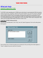
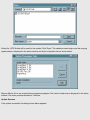
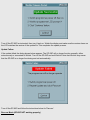
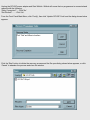


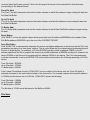
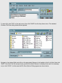
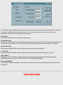
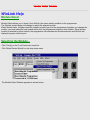


![Rhapsody 2 Owner`s Manual [US]](http://vs1.manualzilla.com/store/data/005663417_1-92bddf67d752d586c47af9cd7ea47d7e-150x150.png)