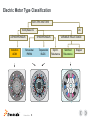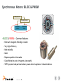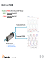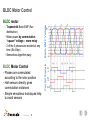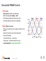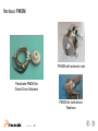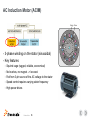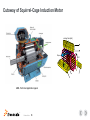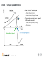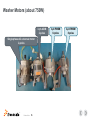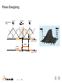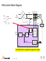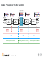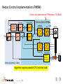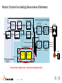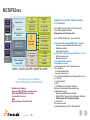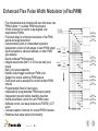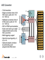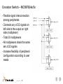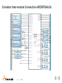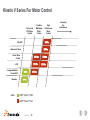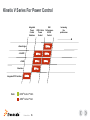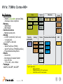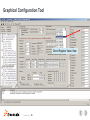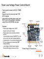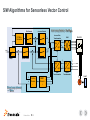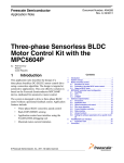
1
Integrated Environment Motor Control FTF-IND-F0256 Zhou Xuwei | Application Engineer M A Y. 2 0 1 4 TM External Use Agenda • Motor Control Introduction • Motor Control Microcontrollers - DSC and Kinetis V • Software Development Tools • Motor Control Enablement TM External Use 1 Motor Control Introduction • Key Motors − Brushless DC (BLDC) Motors − Permanent Magnet Synchronous Motors (PMSM) − AC Induction Motors (ACIM) − Switched Reluctance Motor (SRM) • Key Control Algorithms − Commutation Control (for BLDC Motor) − AC Scalar Control (for ACIM) − AC Vector Control (for ACIM and PMSM) • Challenges in the motor control s/w design TM External Use 2 Motor Control Target Applications • Pumps and fans – pool pumps, factory systems, compressors • HVAC – heating fans, air-conditioners • Industrial drives – manufacturing assembly, robotics, wind turbines, printing presses • Appliances – washers, dishwashers, dryers, fridges, power tools • Medical – scanners, pumps, diagnostic and therapy equipment TM External Use 3 Electric Motor Type Classification ELECTRIC MOTORS DC multi-phase AC ASYNCHRONOUS Induction ACIM SYNCHRONOUS Sinusoidal PMSM TM External Use 4 Trapezoidal BLDC VARIABLE RELUCTANCE Synch. Reluctance Switched Reluctance Stepper Synchronous Motors: BLDC & PMSM multi-phase AC SYNCHRONOUS Sinusoidal PMSM • Trapezoidal BLDC BLDC & PMSM – Common features − Rotor with magnets, Winding on stator − Very high efficiency − High reliability − Quiet − Requires position information − Cost affected by cost of magnets (rare earth) − VERY popular today at low/medium power at both appliance / industrial drives TM External Use 5 BLDC vs. PMSM • BLDC & PMSM differ in Back-EMF Shape − BLDC - Trapezoidal Back-EMF − PMSM - Sinusoidal Back-EMF Trapezoidal BLDC Sinusoidal PMSM Back-EMF Recognition • Rotate with motor shaft • Observe generated voltage TM External Use 6 BLDC Motor Control − − − Trapezoidal Back-EMF (flux distribution) Motor power by commutation “square” voltage – more noisy 2 of the 3 phases are excited at any time (Six-Step) Sensorless algorithm easy BLDC Motor Control • Phases are commutated according to the rotor position • Hall sensors directly gives commutation instances • Simple sensorless techniques help to avoid sensors TM External Use 7 Control Signals − Back-EMF Voltage BLDC motor Ph A Ph B Ph C Sinusoidal PMSM Control • • PMSM motor − Sinusoidal Back-EMF (flux distribution) − Motor power by sine voltage - silent − All 3 phases persistently excited at any time − Sensorless algorithm becomes complicated PMSM Motor Control − Phases are supplied by sine voltage according to rotor position − Requires known start-up position (alignment) − Position Information: − Using Hall Sensors – used rarely Sensorless – several techniques are used Control Algorithm - Vector Control (FOC) TM External Use 8 Trapezoidal BLDC vs. Sinusoidal PMSM • Important Note: − Sometime customers calls both these motors as BLDC regardless of the back-EMF shape. This leads to the confusion since BLDC and PMSM are controlled differently. − It is important to always ask question: Is the motor TRAPEZOIDAL or SINUSOIDAL? TM External Use 9 Various PMSM PMSM with external rotor Panckake PMSM for Direct Drive Washers PMSM for belt-driven Washers TM External Use 10 PMSM & BLDC Motors • Advantages − High torque per frame size − Reliability due to absence of brushes and commutator − Highest efficiency. Renewed interest for “white goods” − Good high speed performance (no brush losses) − Precise speed monitoring and regulation possible − Smooth torque • Drawbacks − Position sensor or sensorless technique is required for motor operation − Difficult to startup the motor using sensorless technique • Typical Applications − Appliance, washer, dishwasher, pump, compressor, dryer, medical, tools, HVAC, fan TM External Use 11 AC Induction Motor (ACIM) Stator Rotor • • 3-phase winding on the stator (sinusoidal) Key features − Squirrel cage (rugged, reliable, economical) − No brushes, no magnet –> low cost − Fed from 3-ph source of the AC voltage to the stator − Speed control requires varying stator frequency − High power drives TM External Use 12 Cutaway of Squirrel-Cage Induction Motor rotating Field (s) Indu c Torque ABB -Technical application paper TM External Use 13 ed c urre nt r ACIM - Torque-Speed Profile • • − Scalar (Speed) Control − Vector Control (Torque) Control For precise control motor speed information needed − Using sensor (Encoder, Tacho) − Sensorless Line Voltage frequency Actual Motor Speed TM External Use Key Control Techniques: 14 AC Induction Motor • Advantages − Low cost per horsepower − Inherent AC operation (Direct connection to AC line) − No permanent magnets (very rugged) − No brushes. Very low maintenance − Available in wide range of power ratings − Low rotor inertia • Drawbacks − Inefficient at light loads. − Speed control requires varying stator frequency. − Position control difficult (field orientation required). • Typical Applications - Washer, pool pump, industrial drives, HVAC, fan, compressor TM External Use 15 Washer Motors (about 750W) 3-ph ACIM 2-poles Single phase AC universal motor 2-poles TM External Use 16 3-ph PMSM 8-poles 3-ph PMSM 8-poles Switched Reluctance Motor (SRM) Phase C • • • • • • Both stator and rotor have salient poles Winding on stator Characterized by magnetization characteristic Y(i, q) Inductance profile linked with rotor position Requires position information for phases commutation Suitable stator/rotor poles ratio configuration (the higher number of phases, the lower torque ripple): − 2-phase:4/2 − 3-phase: 3/2, 6/2, 6/4, 6/8, 12/8, 2/10, 24/32 − 4-phase: 8/6 − 5-phase: 10/8 − 7-phase: 14/12 TM External Use 17 Phase A Phase B Stator (6 poles) Rotor (4 poles) winding (6 stator / 4 rotor poles) Phase A in aligned position Phase Energizing Aligned Unaligned Aligned Stator Phase A Rotor iphA LC LB LA position / time Dwell phase A energizing Turn-ON TM External Use 18 Turn-OFF position / time SR Motor • Advantages − Low cost resulting from simple construction − High reliability − High fault tolerance − Heat is generated in stator: easy to remove − High speed operation possible (100,000 rpm) • Drawbacks − Acoustically noisy − High vibration − Magnetic nonlinearities make smooth torque control difficult − Dependent on electronic control for operation • Typical Applications - Vacuum cleaners, lawn movers, industrial drives TM External Use 19 Complexity of the Motor Control Solutions • Large Variety of MC Algorithm Structure − Processor Dependent (variety of CPU’s & peripherals…) − Motor Type Dependent (ACIM, PMSM, BLDC, DC, Stepper, SR, Linear) − Motor Parameters Dependent (variation of parameters with temperature & current, fluctuation during production, magnetic saturation curves, material of magnets ...) − Algorithm Dependent (FOC, scalar, sensorless, position servo…) − Application Dependent (industrial drive, fan, pump, washer,…..) − Hardware dependent (h/w topology, tolerance of components, noise ….) − Standard’s Dependent (Safety, Autosar, ctm specific standards….) − Co-Existence with other applications (operating system, multi-motor control, PFC…) TM External Use 20 Multi-Dimensional Task One “universal solution” does not work Speed/Torque Control • • Speed Control − Majority of variable speed drives − Speed directly control by applied voltage or by using inner control loop − Speed information necessary Torque (Current) Control − Demanding applications (electrical power steering, electric braking, winding machine, lifts etc…) − Appliance applications (washers, pumps, industrial drives) − Applications requiring the motor to operate with a specified torque regardless of speed − Knowledge of speed & current must be present − Typical algorithm: Vector Control (Field Oriented Control) TM External Use 21 Motor Control Topology DC Bus Three Phase Inverter DC Voltage A DC bus Cap B IGBT / MOSFET Pre- Drivers C Current Feedback PWM Generation Speed/Torque Command Motor Position Feedback Feedback Processing Control Algorithm MCU TM External Use 22 Three Phase Inverter VBus PWM1 PWM3 PWM5 PWM2 PWM4 PWM6 Three-phase PWM waveforms. PWM frequency 10-20kHz -The higher frequency – the higher switching loses - The lower frequency, the higher audible noise Source: Power Electronics, by Ned Mohan, Tore Undeland, and William Robbins, John Wiley & Sons, 1995 TM External Use 23 PWM Applied to Electrical Systems • Load inductance acts like a low pass filter to smooth current. Complementary PWM with DeadTime Peter Pinewski TM External Use 24 Motor Control Topology – Control Algorithm DC Bus Three Phase Inverter DC Voltage A DC bus Cap B IGBT / MOSFET Pre- Drivers C Current Feedback PWM Generation Speed/Torque Command Motor Position Feedback Feedback Processing Control Algorithm MCU TM External Use 25 Basic Types of Motor Control Algorithms • Commutation Control (BLDC) • Volt per Hertz Control (ACIM) • Vector Control (ACIM, PMSM) TM External Use 26 Commutation Control (BLDC) • Six Step BLDC Motor Control − Voltage applied on two phases only − It creates 6 flux vectors − Phases are power based on rotor position − The process is called Commutation − Speed defined by applied voltage − Sensorless control easy (position detection based on back-EMF Zero Crossing) VBus PWM1 PWM3 PWM5 PWM2 PWM4 PWM6 TOP BOTTOM NON Phase voltages TM External Use 27 Commutation Control – BLDC with Sensors Vin AC Cap AC/DC 3-ph BLDC HS PWM's Commutation MCU Speed Command Speed Ramp Speed Contr. + Duty Cycle PWM Gen. BLDC State Machine - Speed Loop Motor Speed Speed Processing (Input capture) 8-bit/20MHz MCU satisfies the algorithm needs TM External Use 28 A B C Hall Sensor Signals BLDC Sensorless Detection Phase A disconnected C O M M U T A T I O N 120o 60o A B C ATOP Switching Sequence BBOTTOM BTOP CBOTTOM CTOP ABOTTOM PWM Motor Ph. A Terminal Voltage ATOP BBOTTOM Back-EMF of Ph. A is visible PWM 0 POSITION INFORMATION When Back-EMF crossing zero TM External Use 29 Scalar Control (ACIM) Also called “Volt-per-Hertz” USE: Low cost AC industrial drives. CONTROL: VOLTAGE (Amplitude and Freq) OPERATION: Attempts to keep magnetizing current constant by varying stator voltage with frequency. Voltage Amplitude (V) Volt/Hertz Ramp Max voltage V F Boost voltage Boost frequency Base frequency Software Control Block Induction IM Motor f (Hz, rpm) Pete Pinewski TM External Use 30 V/Hz Control Block Diagram Rectifier Three-Phase Inverter DC-Bus ~ Line Voltage 230V/50Hz 3-ph AC M = T Over-current fault voltage PWM V V/Hz Speed Set-up Speed Command Processing E + Speed Controller F PWM Generator with Dead Time - Actual Speed Speed Processing (Input Capture) MCU 8-bit/20MHz MCU satisfies the algorithm needs TM External Use 31 Speed Sensing Vector Control (PMSM, ACIM) Also called Field Oriented Control - FOC Vector control ~ control of CURRENT vector (Magnitude and Angle) In special reference frame, the stator currents can be separated into • Torque-producing component • Flux-producing component Q-axis (Torque) ø IS ID ID IQ Software Control Block I MPMSM IQ D-axis (Magnetizing) current feedback Pete Pinewski TM External Use 32 Vector Control for Sinusoidal Motors (PMSM, ACIM) • Vector Control (Field Oriented Control - FOC) is popular technique for nowadays motor drives • Advantages: − Excellent dynamic performance − Full motor torque capability at low speed − Higher efficiency for each operation point in a wide speed range − Decoupled control of torque and flux − Natural four quadrant operation (motor/brake/generator) • Wide variety of control options TM External Use 33 How Difficult Is the Vector Control? It depends on your “point of view”! To mathematically describe barbell motion from a stationary frame of reference would be difficult. However, by jumping on the wheel, and describing the motion from a rotating frame of reference, simplifies the problem immensely! The “q” torque The “d” rotor flux Axis of phase b +a -b -c N S Rotation +b Axis of phase a +c -a Axis of phase c TM External Use 34 Basic Principle of Vector Control Torq Control Flux conttrol Phase B Phase C 3-Phase to 2-Phase d Stationary to Rotating q d Control Process Phase A q Rotating to Stationary Phase A SVM Phase C 2-Phase System 3-Phase System AC DC Stationary Reference Frame TM External Use 35 Rotating Reference Frame Phase B 3-Phase System AC Stationary Reference Frame Vector Control Implementation (PMSM) Critical Loop executed each PWM pulse (10-20kHz) Field Control FW Error Calculator d-current Control Σ Fast Loop (faster) ~50-100ms Inverse Park Transformation ud SVM PWM Inverter uα d,q req Σ Σ Ramp Speed Control α,β uq uβ q-current Control id iq iα d,q α,β Park Transformation q iβ α,β a,b,c Clarke Transformation Speed Position Calculation Slow Loop (slower) ~ 1-5ms Algorithm requires powerful CPU with fast math TM External Use 36 ia ib ic Load a,b E index M Vector Control including Sensorless Estimator Field Control d-current Control FW Error Calculator Fast Loop (faster) ~50-100ms Inverse Park Transformation ud Σ Inverter SVM uα d,q req Σ uq Σ Ramp Speed Control α,β q-current Control id iq q uβ iα d,q α,β Park Transformation Tracking Observe r BEMF Observe r Slow Loop (slower) ~ 1-5ms Sensorless Algorithms calculate speed/position TM External Use 37 iβ α,β a,b,c ia ib ic Clarke Transformation Load M Feedback Processing DC Bus Three Phase Inverter DC Voltage A DC bus Cap B IGBT / MOSFET Pre- Drivers C Current Feedback PWM Generation Speed/Torque Command Motor Position Feedback Feedback Processing Control Algorithm MCU TM External Use 38 Why ADC to PWM Synchronization is needed? • ADC Sampling helps to filter the measured current PWM Period Average Current Inductor Current Sampled Current Synchronized Sampling PWM 0 ADC trigger Signal A/D calc. Data Processing and New PWM Parameters Calculation TM External Use 39 Current Sensing with Shunt Resistors • • Shunt resistors voltage drop measured Dual-sampling required DC Bus +U/2 PWM At CMP2 CMP1 PWM Ct Phase A PWM Ab Internal counter PWM Bt uI_S_A Phase B PWM Bb Phase C PWM Cb uI_S_B uI_S_C - U/2 Ground iSB Desired PWM DT2 Complementary pair with dead time inserted (signals at pins) Rising edge is shifted by DT Mid point shifts Real feedback signal at ADC pin ADC Sampling Point TM External Use 40 Shunt resistors iSA n iSC 3-ph AC Induction Motor 3-ph PM Synchronous Motor Position Sensing • Position and velocity measurement is often required in feedback loops • Position measurement: − Potentiometers Potentiometers − Optical Encoders − Linear Variable Differential Transformer − Resolvers − Sin-Cos • Encoders Velocity measurement: − Tachogenerator Resolvers TM External Use 41 Optical Encoders • Encoders are digital Sensors commonly used to provide position feedback for actuators • Consist of a glass or plastic disc that rotates between a light source (LED) and a pair of photo-detectors • Disk is encoded with alternate light and dark sectors so pulses are produced as disk rotates • The current position is calculated by incrementing/decrementing the pulse edges. • The direction of counting is determined by phase shift of two quadrature pulses Scanning Principle Incremental Encoder Pulses There are 4 phases within one pulse cycle. You need for example (360/0.5)/4=180 pulses per rotation if 0.5deg resolution is wanted. TM External Use 42 Motor Control Topology DC Bus Three Phase Inverter DC Voltage A DC bus Cap B IGBT / MOSFET Pre- Drivers C Current Feedback PWM Generation Speed/Torque Command Motor Position Feedback Feedback Processing Control Algorithm MCU TM External Use 43 Challenges in Motor Control Development TM External Use 44 Motor Control Challenges Not just s/w, but combination of s/w algorithms and MCU peripherals with special features and mutual interconnection between them Position decoder • • • MC Timer − PWM signals < 20Khz with dead time insertion − ADC triggering − Fault control Fault inputs ADC − Measure current, voltage, temperature − simultaneous sampling of two currents − ADC sampling synchronized with PWM Comparator & DAC Delay block − • 6 ch PWM timer Set ADC measurement at specific times Prog delay Position decoder − Quadrature decoder inputs if not sensorless • Comparator − with DAC 12 bit ADC Eliminate need of external components TM External Use 45 Motor Control Challenges Critical real time operation – interrupt each 25-125usec • • • S/W must: − sample current, voltage at precise moment (synchronized with PWM) − calculate current control loop (filters, transformation, controllers, ripple elimination, estimators / observers) − calculate output values for PWM (SVM), update output registers − configure next ADC conversion Sampled and Average Currents Fast control loop for PMSM sensorless drive includes: − 63 MAC − 54 MUL − 6 DIV − 56 ADD/SUB Phase Current Shunt Resistor Signals PWM top Fast sensorless control loop takes: − PWM Period 21 usec on 56800E core @ 100MHz PWM Bottom A/D calc. New PWM Parameters Calculation with Half-cycle Reload TM External Use 46 Motor Control Challenges • Electro- Mechanical System – debugging includes power h/w − Safety: − galvanic isolation between debugger and application required (opto, RF) Debugging: s/w cannot be just stopped during application debugging to see what’s going on Standard debugger not sufficient for motor control application debugging Real Time Graph as a Real-time Debugger - Variables - Real-time waveforms - High-speed recorded data Variable Watch TM External Use 47 Motor Control Challenges Solution at technical limits driven by cost • Applications Complexity − low cost motors with wild parameters − low cost h/w, sensorless − limited CPU performance − low-cost MCU peripherals − Applications development often requires expert MC know-how and experience TM External Use 48 DSC & it’s Peripherals • For Motor Control and Power Conversion Applications TM External Use 49 DSC Roadmap Performance 120MHz 32-bit Core 256K Flash FPU MC56F85xx 56F8441 – 100MHz 32-bit Core 256K Flash DMA, UHS ADC, Ultra-Hi Res PWM MC56F824x/5x MC56F802x/3x MC56F803x – 32MHz Hi Res PWM, CAN, ADC, DAC MC56F802x – 32MHz Hi Res PWM, ADC, DAC MC56F801x MC56F801x – 32MHz Hi Res PWM, ADC MC56F825x – 60MHz 64K Flash Ultra-Hi Res PWM, UHS ADC MC56F824x– 60MHz 48K Flash Ultra-Hi Res PWM, UHS ADC 568432/1 – 100MHz 32-bit Core 128K Flash DMA, UHS ADC, Ultra-Hi Res PWM 56F8422/1 – 100MHz 32-bit Core 64K Flash DMA, UHS ADC, Ultra-Hi Res PWM New 50/100MHz 64K Flash Ultra-Hi Res PWM UHS ADC MC56F82xxx MC56F84xxx MC56F800x MC56F800x – 32MHz Hi Res PWM Available Low power Small Flash Blocks Hi Res PWM MC56F80xx Announced Planned Future Proposed TM External Use 50 Freescale DSC Family Compatibility 256 56F84xxx 64 NVM KB 128 48 32 56F84xxx 56F84xxx 56F84xxx 56F84xxx 56F8255 56F8256 56F8257 56F82xxx 56F82xxx 56F82xxx 56F8245 56F8246 56F8247 56F82xxx 56F82xxx 56F82xxx Available PIN COMPATIBLE Package Announced Planned 56F84xxx 44LQFP 48LQFP TM External Use 51 64LQFP 80 / 100LQFP Mapping the Architecture to DSP Algorithms PROGRAM CONTROLLER AGU PC LA LA2 INSTRUCTION DECODER HWS FIRA FISR INTERRUPT UNIT SR OMR LC LC2 ALU1 Common Operation in DSP ALU2 MAC X0, Y0, A M 01 N3 LOOPING UNIT R0 R1 R2 R3 R4 R5 N SP Arithmetic Op Program Memory XAB1 XAB2 PAB PDB CDBW CDBR XDB2 BIT MANIPULATION UNIT EOnCE / JTAG TAP A B C D Y0 Y1 X0 DATA ALU MAC and ALU TM External Use 52 Multi-bit Shifter Data Memory X:( R4)+, Y1 X:( R3)+, C 1st Read 2nd Read Operations Performed: • Multiply-Accumulate • 3 Memory Accesses • 2 Address Additions Instruction Fetch: PAB PDB - 21 bits - 16 bits IP-Bus Interface 1st Data Access: External Bus Interface 2nd Data Access: XAB1 - 24 bits CDBR - 32 bits XAB2 - 24 bits XDB2 - 16 bits DSP56800E Version 3 Core Improvement (the differences between V2 core and V3 core) New Instructions • 32 x 32 -> 32/64 Multiply and MAC Instructions • IMAC32 - Integer Multiply-Accumulate 32 bits x 32 bits -> 32 bits IMPY32 - Integer Multiply 32 bits x 32 bits -> 32 bits IMPY64 - Integer Multiply 32 bits x 32 bits -> 64 bits IMPY64UU - Unsigned Integer Multiply 32 bits x 32 bits -> 64 bits MAC32 - Fractional Multiply-Accumulate 32 bits x 32 bits -> 32 bits MPY32 - Fractional Multiply 32 bits x 32 bits -> 32 bits MPY64 - Fractional Multiply 32 bits x 32 bits -> 64 bits Multi-Bit Clear-Set instruction to improve flexibility of peripheral register handling – BFSC (test bitfield and set/clear). Other Features • Bit Reversed Address Mode For FFT algorithms. • Swap all address generation Unit Registers with Shadowed registers to reduce Interrupt context switch latency. TM External Use 53 MC56F84xx Features • 100 MHz/100MIPS 56800 V3 Core − − • • • • • • • 32kB Data Flash with 2kB eEE 2 Periodic Timers with Real Time Interrupt Generation 2 Programmable Delay Blocks 8Ch multifunction timers 8ch High Resolution PWM Channels 312ps PWM and PFM resolution 8ch PWM Channels with Input Capture 8ch x 2 12-bit ADC converter with built-in PGA − • 32kB Program/Data RAM 3 HS-QSCI (8MBS) , 3xQSPI, 2xIIC/SMBus, 1xFlexCAN Multi-purpose timers − • • 256kB Program/Data Flash 2.7-3.6V Operation 256kB Program/Data FLASH 32kB Data Flash with up to 2kB of eEE 32kB Data/Program RAM Resource Protection Unit − − − • Harvard architecture 32 x 32bit MAC and 32bit arithmetic operation 300ns/3.33Msps conversion time with 12bit resolution 8ch 16bit SAR ADC with built-in temperature sensor and band gap. − 2us conversion time. • • • • • • • 4 Analog Comparators 1 Quadrature Decoder 1ch 12bit DAC with external outputs + 4ch 6bit DAC DMA controller Inter-Module Crossbar On-chip voltage regulator (Single 3.3V Power Supply) System Integration : Internal relaxation oscillator, PLL, COP, 32kHz , EWM, auxiliary Internal clock, low voltage detect, EZPort • 5V tolerant I/O • Temperature Range: -40 C to +105 C TM External Use 54 8ch 12bit ADCA Prog Gain Amp Ax1,2,4 8ch 12bit ADCB Prog Gain Amp Bx1,2,4 CRC Crystal Oscillators 8-ch PWM /w Capture 8-ch High Res PWM 1 Quadrature Decoders Memory Resource Protection Unit PLL 56800E V3 Core 100MHz JTAG/EOnCE & 4x 6bit DAC Relaxation OSC 8MHz 1ch 12bit DAC Internal 32KHz Clock 4 Analog Comparators 2 x PIT (RTC) 2 x PDB Inter-Module XBar 8Ch 16bit Quad Timer 3 x QSPI ezPort Voltage Regulator 2x IIC/SMbus System Integration Module (SIM) COP 1 x FlexCAN POR 3 x HS QSCI Interrupt Controller LVI 16ch 16bit ADC /w Temp DMA Controller GPIO 48 LQFP, 64 LQFP, 80LQFP, 100LQFP 56F8400 Series Feature Summary TM External Use 55 MC56F82xxx 64KB Flash Program Flash 8KB SRAM Data RAM PLL 4Ch DMA Crystal OSC CRC 8MHz OSC Band-gap Ref 32KHz OSC 2 x 12bit DAC Memory Resource Protection 8-Ch 12bit ADCA w/ PGA 8-Ch 12bit ADCB w/ PGA 16KB Flash 56800EX Core Inter-module Cross Bar 50MHz/40MHz 8-Ch PWM • • 56800EX V3 Core @ 50MHz (100MHz from RAM) 2.7-3.6V Operation • • • Up to 64KB Program FLASH ,with Flash Security Up to 6KB Program/Data RAM Memory Resource Protection Unit • Up to 100 MHz Peripherals – Timers and SCIs • 4-Ch 16bit Timer 4x Analog Comp 2K B SRAM Memory Options JTAG/EOnCE Voltage Regulator 1 x MSCAN 2 COP 2 x HS SCIs System Integration Module (SIM) POR 2 x SPI LVI IIC/SMbus 32QFN, 32LQFP, (44LQFP), 48LQFP & 64LQFP • • • • • • • Packages will be pin compatible with the MC56F824x/5x and MC56F84xx Breakthrough Features: High speed ADC @ 800ns conversion time Nano Edge PWM @ 512ps Resolution Inter-module Cross bar DMA Memory Resource Protection Unit TM External Use 56 Eight Channel Nano Edge PWM (512ps resolution) Up to four programmable fault protection input Dead-time insertion Input Capture function 2 x12-bit ADCs with total 16 Inputs & PGAs 1x, 2x, 4x − 800ns conversion rate − Band-gap reference Four channel DMA controller Inter Module cross-bar 4 x Comparators with a 6bit Voltage reference CRC Generator 2 x Windowed Watchdog − − − • • • • • • • External Watchdog Monitor 4 x 16-bit Enhanced Multifunction Programmable Timers 2 x 12b DAC 2 x High Speed SCI 2 x SPI 1x I2C/SMbus Communications Interface Software Programmable Phase Locked Loop Multiple Clock sources − External Crystal/Resonator Oscillator − 8MHz/200KHz Tunable Internal Relaxation Oscillator − 32KHz Internal RC relaxation Oscillator • 5v Tolerant IO • Error code correction • Industrial temperature:-40C to 105C @ 50MHz 56F82xxx Series Feature Summary TM External Use 57 Enhanced Flex Pulse Width Modulator (eFlexPWM) • Four independent sub-modules with own time base, two PWM outputs + 1 auxiliary PWM input/output • 16 bits resolution for center, edge aligned, and asymmetrical PWMs • Fractional delay for enhanced resolution of the PWM period and edge placement • Complementary pairs or independent operation • Independent control of both edges of each PWM output • Synchronization to external hardware or other PWM sub-modules • Double buffered PWM registers • Integral reload rates from 1 to 16 include half cycle reload • Half cycle reload capability • Multiple output trigger events per PWM cycle • Support for double switching PWM outputs • Fault inputs can be assigned to control multiple PWM outputs • Programmable filters for fault inputs • Independently programmable PWM output polarity • Independent top and bottom deadtime insertion • Individual software control for each PWM output • Software control, and swap features via FORCE_OUT event • Compare/capture functions for unused PWM channels • Enhanced dual edge capture functionality TM External Use 58 eFlexPWM – 56F824x/5x – Block Diagram – Sub-ModuleX PWM generation – block diagram Force Out Logic PWM Generator Clock PWM pattern – top transistor PWM pattern – bottom transistor PWM23 PWM gen - PWM23 Software - OUT23 External signal - EXTA PWM45 PWM gen – PWM45 Software – OUT45 External signal - EXTB PWM23 Deadtime Insertion Independent/Complementary PWM45 operation + Deadtime insertion PWM23 PWMA output PWMB output TM External Use 59 PWM45 Output Logic PWM23 Mask control Polarity control PWM output enable/disable Fault control PWM45 Fractional delay 23 – 5-bit & Fractional delay 45 – 5-bit Fractional Delay A/D Converter • • • • • • • • 12-bit resolution Single conversion time of 8.5 ADC clock cycles (8.5 × 50 ns = 450 ns) Additional conversion time of 6 ADC clock cycles (6 × 50 ns = 300 ns) ADC to PWM synchronization Scans and stores up to eight measurements each on two ADC converters Multi-triggering support Gains the input signal by x1, x2, or x4 Optional sample correction by subtracting a preprogrammed offset value TM External Use 60 VRETH ANA0 ANA1 ANA2 ANA3 ANA4 ANA5 ANA6 ANA7 VREFLO Voltage Reference Circuit Result Reg 0 Result Reg 1 Result Reg 2 MUX S/H & Scaling Cyclic Converter A Result Reg 3 12 Result Reg 8 Result Reg 9 Result Reg 10 SYNC0 SYNC1 Result Reg 11 Controller Result Reg 4 Result Reg 5 ANB0 ANB1 ANB2 ANB3 ANB4 ANB5 ANB6 ANB7 MUX S/H & Scaling Result Reg 6 Cyclic Converter B Result Reg 7 12 Result Reg 12 Result Reg 13 Result Reg 14 Result Reg 15 Crossbar Switch – MC56F824x/5x • • • • • Flexible signal interconnection among peripherals Connects any of 22 signals on left side to the output on right side (multiplexer) Total 30 multiplexers All multiplexers share the same set of 22 signals Increase flexibility of peripheral configuration according to user needs TM External Use 61 Crossbar Inter-module Connection–MC56F824x/5x TM External Use 62 Crossbar Inter-module Connection – MC56F84xxx AND-OR-INV Logic AND-OR-INV Logic AND-OR-INT Logic AND-OR-INV Logic Crossbar B 16 4 8 4 10 4 n n n n n n n6 n n n n DMA Req INT eFlexPWM HS-CMP Timer Q_Decoder I/O PDB Crossbar A TM External Use 63 Kinetis V & it’s Peripherals • For Motor Control Applications TM External Use 64 Kinetis V-Series Motor & Power Control • Full Kinetis portfolio compatibility targeting low cost, stand alone motor control, to high performance digital power conversion • Optimized for processing efficiency with performance ranging from 75MHz to beyond 200MHz • ARM architecture with best in class, high speed capture and control peripherals for motor control and power management applications • Enablement and tools built around reducing customer development time and cost, whilst increasing ease of use. TM External Use 65 Kinetis V Series Target Applications Motor Control • • Solar Inverters Sensored BLDC / PMSM • • Grid-Tied High Dynamic Control • Sensored ACIM • Sensorless VOC • Digital Power Conversion • Non Grid Tied • Power factor correction • PMSM/BLDC • High Dynamic Control • Low Dynamic Control • Switch Mode Power Supplies • AC/DC • DC/DC Sensorless ACIM • UPS • On-Line • Offline • Inductive cooking • Multi cook plate TM External Use 66 Kinetis V Series For Motor Control Entry Level FOC Motor Control Scalable Mid Range Motor Control KV4x + HS ADC KV4x + Advanced Timers KV3x + Dual Motor Control KV3x + FPU + Integrated Motor Control S/W KV1x Core: KV3x KV1x Baseline High Performance Motor Control ARM® Cortex™-M0+ ARM® Cortex™-M4 TM External Use 67 KV4x KV4x Increasing the performance Kinetis V Series For Power Control Integrated Power Control Solutions UPS & Solar Power Control KV4x + Nano Edge KV4x + HS ADC KV4x + CAN KV4x Baseline Integrated PFC Solution Core: KV3x ARM® Cortex™-M0+ ARM® Cortex™-M4 TM External Use Mid Performance AC/DC Control 68 KV4x KV4x Increasing the performance KV1x: 75MHz Cortex-M0+ Key Features: • Core/System − 75MHz Cortex-M0+ with 4ch DMA • 4ch-DMA Clocks Phase & FrequencyLocked Loop Low/High Frequency Oscillators Internal Reference Clocks Multiple serial ports 2 x 8ch 12-bit ADC (1uS conv) 1 x12-bit DAC 2 x ACMP w/ 6b DAC Security and Integrity 1x6ch FlexTimer (PWM) 1x2ch FlexTimer (PWM/Quad Dec.) Programmable Delay Block Others − − − − • SRAM 8KB InterModule Crossbar Interrupt Controller Timers − − − • Program Flash 32KB Analog − − − • 32KB Flash 8KB SRAM HW Divide & SqrRoot Internal and External Watchdogs Communications − • ARM Cortex-M0+ 75MHz Debug Interfaces Memory − − • Hardware divide & SqrRoot Memories System Core Timers Communication Interfaces 2 x12-bit ADC 6ch FlexTimer 1xI2C 2 x ACMP 2ch FlexTimer 2xUARTs 1 x12-bit DAC Programmabl e Delay Block 1xSPI Periodic Interrupt Timers 32-bit CRC Intermodule Crossbar Switch Up to 35 I/Os 1.71V-3.6V; -40 to 105oC Low-Power Timer Packages 32QFN, 32LQFP, 48LQFP Typical applications: • BLDC sensorless • PMSM Sensorless FOC Low Dynamic • ACIM V/Hz and FOC Low Dynamic TM External Use Cyclic Redundancy Check (CRC) Analog 70 HMI GPIO KV1xs 75MHz: Part Numbers Max. Pin Packag MC Part Number Freq. Count e Flash SRAM DMA PLL FTMs DAC MKV10Z32VLF7 MKV10Z32VLC7 MKV10Z32VFM7 MKV10Z16VLF7 MKV10Z16VLC7 MKV10Z16VFM7 4-ch 4-ch 4-ch 4-ch 4-ch 4-ch Yes Yes Yes Yes Yes Yes 1x6ch; 1x2ch 1x6ch; 1x2ch 1x6ch; 1x2ch 1x6ch; 1x2ch 1x6ch; 1x2ch 1x6ch; 1x2ch 1 1 1 1 1 1 75MHz 75MHz 75MHz 75MHz 75MHz 75MHz 48 32 32 48 32 32 LQFP LQFP QFN LQFP LQFP QFN TM External Use 71 32K 32K 32K 16K 16K 16K 8KB 8KB 8KB 8KB 8KB 8KB KV3x – 128K Flash – 100MHz Key Features: • Core/System − • ARM Cortex-M4 100MHz Debug DSP Interface s Interrupt Cortex-M4 @ 100MHz Memory − 128KB Flash, − 16KB SRAM • • Controlle r Communications − Clocks SRAM 16KB FrequencyLocked Loop Low/High Frequency Oscillators 4ch-DMA LowLeakage Wake-Up Unit Analog Security and Integrity Cyclic Redundancy Check (CRC) Timers − 1x6ch FTM (PWM) − 2x2ch FTM (PWM/Quad Dec.) − Low Power Timer Analog Timers FlexTime r 1xI2C 2x ACMP Programma ble Delay Block 2xUARTs 1 x12-bit DAC Periodic Interrupt Timers LowPower Timer Others Up to TBD I/Os − 6 high-drive I/Os (20mA) – SPI/I2C − 1.71V-3.6V; -40 to 105oC Typical applications: • PMSM Sensorless FOC • ACIM FOC • Dual MC Packages 32QFN, 48LQFP, 64LQFP TM External Use 72 Communication Interfaces 2 x16-bit ADC − • Memories Program Flash 128KB Internal Reference Clocks 2 x16-bit ADC − 1 x12-bit DAC − 2 x ACMP • and External Watchdog s Multiple serial ports − • System Internal Core 1xSPI HMI GPIO KV3x – 128K Flash – 100MHz / FPU Key Features: • Core/System − • Cortex-M4 @ 100MHz / FPU Memory − • System Arm Cortex-M4 100MHz Internal and External Watchdogs 128KB Flash, − 24KB SRAM Debug Interfaces DSP 4ch-DMA Communications Interrupt Controller FPU LowLeakage Wake-Up Unit − • Core Multiple serial ports Memories Program Flash 128KB SRAM 24KB Serial Programming Interface (EzPort) FrequencyLocked Loop 32-byte Register File 2 x16-bit ADC − 1 x12-bit DAC − 2 x ACMP Security and Integrity Cyclic Redundancy Check (CRC) Timers − 1x8ch FTM (PWM) − 2x2ch FTM (PWM/Quad Dec.) − Low Power Timer • Analog 2 x16-bit ADC 2 x ACMP Programmabl e Delay Block 4xUARTs 2 x12-bit DAC Periodic Interrupt Timers Low-Power Timer Up to TBD I/Os − 6 high-drive I/Os (20mA) – SPI/I2C − 1.71V-3.6V; -40 to 105oC Packages Standard Feature 64LQFP, 100LQFP TM External Use Communication Interfaces 2xI2C Others − Timers FlexTimer − • Low/High Frequency Oscillators Internal Reference Clocks Analog − • Clocks 73 Optional Feature 2xSPI HMI GPIO KV3x – 512K/256K Flash – 120MHz Key Features: • Core/System − • Cortex-M4 @ 120MHz / FPU Memory − up to 512KB Flash, − up to 128KB SRAM − FlexBus (External Bus Interface) • Communications − • Debug Interfaces DSP 16ch-DMA Interrupt Controller FPU Low-Leakage Wake-Up Unit Memories Security and Integrity Cyclic Redundancy Check (CRC) Timers up to 2x8ch FTM (PWM) − 2x2ch FTM (PWM/Quad Dec.) − Low Power Timer Analog 2 x16-bit ADC Timers SRAM up to128KB PhaseLocked Loop Serial Programming Interface (EzPort) FlexBus External Bus Interface FrequencyLocked Loop 32-byte Register File − Up to TBD I/Os − 6 high-drive I/Os (20mA) – SPI/I2C − 1.71V-3.6V; -40 to 105oC Packages 64LQFP, 100LQFP TM External Use 74 Communication Interfaces FlexTimer 2xI2C 2 x ACMP Programmabl e Delay Block 4xUARTs 2 x12-bit DAC Periodic Interrupt Timers Low-Power Timer Others − Clocks Program Flash Up to 512K Analog − • Arm Cortex-M4 120MHz Internal and External Watchdogs Low/High Frequency Oscillators Internal Reference Clocks 2 x16-bit ADC − Up to 2 x12-bit DAC − 2 x ACMP • System Multiple serial ports − • Core 2xSPI HMI GPIO KV3x -100/120MHz Part Numbers MC Part Number Max. Freq. Pin Count Package Flash SRAM Flex.Bu s DMA PLL MKV10FN512VLL12 120MHz 100 LQFP 512K 96KB Yes 16-ch Yes MKV10FN512VLH12 120MHz 64 LQFP 512K 96KB Yes 16-ch Yes MKV10FN256VLL12 120MHz 100 LQFP 256K 48KB No 16-ch Yes MKV10FN256VLH12 120MHz 64 LQFP 256K 48KB No 16-ch Yes MKV10FN128VLL10 100MHz 100 LQFP 128K 24KB No 4-ch No MKV10FN128VLH10 100MHz 64 LQFP 128K 24KB No 4-ch No MKV10DN128VLH1 100MHz 0 64 LQFP 128K 16KB No 4-ch No MKV10DN128VLF10 100MHz 48 LQFP 128K 16KB No 4-ch No MKV10DN128VFM1 100MHz 0 32 QFN 128K 16KB No 4-ch No TM External Use 75 FTMs 2x8ch; 2x2ch 2x8ch; 2x2ch 1x8ch; 2x2ch 1x8ch; 2x2ch 1x8ch; 2x2ch 1x8ch; 2x2ch 1x8ch; 2x2ch 1x8ch; 2x2ch 1x8ch; 2x2ch DAC I/O w/ dig. Filters 2 16 2 16 1 8 1 8 1 8 1 8 1 8 1 8 1 8 FlexTimer Module • • • • • • • • • • • • • • • • • • FTM source clock is selectable with prescaler divide-by 1, 2, 4, 8, 16, 32, 64, or 128 FTM has a 16-bit counter 2 up to 8 channels (inputs/outputs) The counting can be up or up-down Each channel can be configured for input capture, output compare, or Input filter can be selected for some channels New combined mode to generate a PWM signal Complementary outputs, include the deadtime insertion Software control of PWM outputs Up to 4 fault inputs for global fault control The polarity of each channel is configurable The generation of an interrupt per channel input capture/compare, counter overflow, at fault condition Synchronized loading of write buffered FTM registers Write protection for critical registers Backwards compatible with TPM Dual edge capture for pulse and period width measurement Quadrature decoder with input filters, relative position counting and interrupt on Position count or capture of position count on external event TM External Use 76 FlexTimer Module Diagram TM External Use 77 Build-in Comparator • • • • • TM External Use 78 Continuous, Sampled, Windowed modes Programmable filter and hysteresis Up to eight independently selectable channels for positive and negative comparator inputs External pin inputs and several internal reference options including 6-bit DAC, 12-bit DAC, bandgap, VREF, OpAmp, 6-bit DAC − Output range (Vin/64) to Vin − VREF or VDD selectable as DAC reference 16-bit ADC – Analog Quantities Measurement • • • • • • • • • • • • • TM External Use 79 Up to 4 pairs of differential and 24 single-ended external analog inputs Single or continuous conversion (automatic return to idle after single conversion) Configurable sample time and conversion speed/power Input clock selectable from up to four sources Operation in low power modes Asynchronous clock source for lower noise operation Selectable hardware conversion trigger with hardware channel select Automatic compare with interrupt for less-than, greater-than or equal-to, within range,or out-ofrange, programmable value Temperature sensor Hardware average function Selectable voltage reference: external or alternate Self-calibration mode Programmable Gain Amplifier (PGA) with up to x64 gain Programmable Delay Block (PDB) TM External Use 80 • The PDB provides delays between input and output triggers • Up to 4 channels available (one for each ADC) with two pretriggers • Trigger 0 => Sample A • Trigger 1 => Sample B S/W Development Tools • FreeMASTER • QuickStart TM External Use 81 as a Real-time Monitor TM External Use 82 FreeMASTER PC Master functionality categories: – Monitor functions: watching on-board memory locations (board application variables) in various formats: • textual in the tabular form • real-time charts of the values (oscilloscope via RS232) • graphs of high-speed recorded data (on board memory oscilloscope) – Control functions: • setting the variable values asynchronously to the on board application • stimulating the variable values according to specific time-table • sending “user commands” as an official message to the board application The Communication Library Communication through: • SCI, UART • JTAG/OnCE (DSC, Kinetis) • BDM (HCS08, HCS12) • CAN • Ethernet, TCP/IP • Bluetooth Link Protocol Implementation Module TM External Use 83 as a Real-time Monitor • Connects to an embedded application − SCI, UART − JTAG/EOnCE (DSC, Kinetis) − BDM (HCS08, HCS12) − CAN Calibration Protocol − Ethernet, TCP/IP − Any of the above remotely over the network • Enables access to application memory − Parses ELF application executable file − Parses DWARF debugging information in the ELF file − Knows addresses of global and static C-variables − Knows variable sizes, structure types, array dimensions etc. TM External Use 84 Control Page Example TM External Use 85 Scope Example Real Time Graph • Similar to the classical hardware oscilloscope • Variables read in realtime • Sampling time limited by communication data link Variable Watch TM External Use 86 Recorder Example • • • • Variables recorded by the embedded-side timer periodic ISR After requested number of samples data stored in Recorder buffer Sample very fast actions Buffer download can be defined TM External Use 87 Recorded Graph Stimulator Example TM External Use 88 What is ? Application control and monitor Live graphs, variable watches, and graphical control page Real-time operation monitor TM External Use 89 S08 Kinetis DSC S12 Power Arch. ColdFire…. QuickStart TM External Use 90 What is QuickStart? Quick Start = Easy-to-use SW Development Environment for DSC • QuickStart includes − Set of Low-level Drivers for all Peripheral Modules − Ready-to-use Project Templates (“Project Stationery”) − Graphical Configuration Tool − Sample Applications − User Manual • QuickStart − Designed according to customer needs − Supports all DSC’s including latest 56F82xxx/4xxx − Mandatory development tool for key appliance customers (Electrolux, Indesit, Miele, DiehlAKO, Emerson, PowerOne, etc) TM External Use 91 Low-level Drivers • Quick Start Low-level Drivers − Full control over and full access to all processor resources − Unifies access to peripheral memory space (ioctl call) − Registers are not accessed directly, although this is still possible − ioctl calls are optimally compiled macros or functions ioctl(SCI_0, SCI_SET_BAUDRATE, SCI_BAUD_9600) Module identifier Command to perform TM External Use 92 Command Parameter Graphical Configuration Tool • Features: − − − − − Edits post-reset processor configuration graphically Configuration saved/read from a single ANSI C header file GUI to configuration bits of all peripheral module registers Possible conflict warnings Pin-out view of processor I/O pins TM External Use 93 Graphical Configuration Tool • Used to edit the ANSI C-compatible application configuration header file (appconfig.h) • appconfig.h contains a single macro constant per peripheral register Ctrl+F10 invoked GCT opens the appconfig.h for a current project appconfig.h file Metrowerks CodeWarrior IDE #include “appconfig.h” #defines used to initialize peripherals Read & Write access to appconfig.h TM External Use Graphical Configuration Tool 94 Graphical Configuration Tool Different Control Page for each Peripheral Module Module Configuration Page Clocks Summary Registers Summary Warnings Summary Peripheral Modules Tree TM External Use 95 Graphical Configuration Tool Direct Register Value View TM External Use 96 Motor Control Enablement • Hardware Kits • Algorithm Software Libraries • IEC60730 Safety Libraries • MC Reference Designs • MC Application Tuning (MCAT) TM External Use 97 Motor Control Hardware Kits TM External Use 98 Tower Low Voltage Power Control Board • • • • Tower system module for BLDC / PMSM control Support most of current and new TWR MCU modules Launched kit includes power supply and BLDC motor with application examples using K40 and MC56F825x devices Features: − − − − − − − − Power supply voltage input 24VDC Output current up to 8 Amps Power supply reverse polarity protection circuitry 3‐phase bridge inverter (6‐MOSFET’s) with over-current and under-voltage protection 3‐phase and d.c. bus‐current‐sensing shunts DC bus‐voltage and 3‐phase back‐EMF voltage sensing Low‐voltage on‐board power supplies Encoder/Hall sensor sensing circuitry Product Page at Freescale.com: TWR-MC-LV3PH TM External Use 99 3-ph BLDC/PMSM High Voltage MC Drive • • Main board + MCU daughter cards Available MCU cards: − − − − − • MC9S08MP16 MC56F8006 / MC56F8013 / MC56F8023 MC56F8257 MC56F82xxx K40X256 Board Features: − − − − − − − − − − Input Voltage 115-230Vac, 50/60Hz / Output Power 1kW 3-phase IGBT inverter bridge with over-current protection Interleave PFC (coming in Rev2) • 3-phase motor current and BEMF sensing DC-Bus current and voltage sensing • Isolated SCI / USB interface User LED’s Encoder / Hall Sensor and tacho interface DC-Brake Isolated JTAG (in Rev 2) TM External Use 100 Rev.1 – prototypes - Available per specific business opportunities Rev.2 – productization – in progress, to be available in Q1 2014 Embedded Software Libraries TM External Use 101 S/W Algorithms for Sensorless Vector Control Field Control FW Error Calculator d-current Control Fast Loop (faster) ~50-100ms Inverse Park Transformation ud Σ Inverter SVM uα d,q req Σ uq Σ Ramp Speed Control α,β q-current Control id iq q iα d,q α,β Park Transformation Tracking Observe r Slow Loop (slower) ~ 1-5ms TM External Use uβ 102 BEMF Observe r iβ α,β a,b,c ia ib ic Clarke Transformation Load M Embedded Software Libraries • Set of basic trigonometric, general math, filter & motor control algorithms as the building blocks for the motor control applications • Provided in highly optimized layered architecture, support of 16/32-bit fixed-point and single precision floating point • Matlab/Simulink models included in the package • Delivered as object file for the evaluation purposes for free, source code under specific business conditions TM External Use 103 Freescale Embedded Software and Motor Control Libraries Algorithms divided into five sub-libraries: • Mathematical Library (MLIB) contains basic math functions. • General Function Library (GFLIB) contains trigonometric, look-up table and control functions. These software modules are basic building blocks. • Motor Control Library (MCLIB) contains vector modulation, transformation and specific motor related functions to build digitally controlled motor drives. • General Digital Filter Library (GDFLIB) contains filter functions for signal conditioning. • Advanced Control Library (ACLIB) contain functions to enable building the variable speed AC motor drive systems with field oriented control techniques without position or speed transducer TM External Use 104 Math and Motor Control Library Set Note: • • MC Lib for 56800E – Math functions included into the individual algorithms MC Lib for Kinetis and 56800EX - Math functions separated into MLIB TM External Use 105 Math and Motor Control Library Set – Contents MLIB GFLIB Absolute Value, Negative Value • • • • MLIB_Abs, MLIB_AbsSat MLIB_Neg, MLIB_NegSat • Add/Subtract Functions • • • • MLIB_Add, MLIB_AddSat MLIB_Sub, MLIB_SubSat • • • • • • MLIB_Mul, MLIB_MulSat MLIB_Div, MLIB_DivSat MLIB_Mac, MLIB_MacSat MLIB_VMac • • • • • MLIB_ShL, MLIB_ShLSat MLIB_ShR MLIB_ShBi, MLIB_ShBiSat • • • • MLIB_ConvertPU, MLIB_Convert • GFLIB_ControllerPIr, GFLIB_ControllerPIrAW GFLIB_ControllerPIp, GFLIB_ControllerPIpAW GDFLIB_FilterMA 1st Order Infinite Impulse Filter • • • GDFLIB_FilterIIR1init GDFLIB_FilterIIR1 2nd Order Infinite Impulse Filter • • GDFLIB_FilterIIR2init GDFLIB_FilterIIR2 Clark Transformation • • • GDFLIB_FilterFIR Moving Average Filter • • GMCLIB_Clark GMCLIB_ClarkInv Park Transformation • • • GMCLIB_Park GMCLIB_ParkInv Duty Cycle Calculation • • • • • • Angle Tracking Observer Tracking Observer PMSM BEMF Observer in Alpha/Beta PMSM BEMF Observer in D/Q GMCLIB_SvmStd Elimination of DC Ripples • • GMCLIB_ElimDcBusRip Decoupling of PMSM Motors • • GMCLIB_DecouplingPMSM GFLIB_Lut1D, GFLIB_Lut2D GFLIB_Hyst Signal Integration Function • Conversion Functions • • ACLIB/AMCLIB Hysteresis Function • MLIB_Norm, MLIB_Round Finite Impulse Filter • GMCLIB Interpolation • Normalisation, Round Functions • GFLIB_Limit, GFLIB_VectorLimit GFLIB_LowerLimit, GFLIB_UpperLimit PI Controller Functions • Shifting • GFLIB_Sin, GFLIB_Cos, GFLIB_Tan GFLIB_Asin, GFLIB_Acos, GFLIB_Atan, GFLIB_AtanYX GFLIB_AtanYXShifted Limitation Functions • Multiply/Divide/Addmultiply Functions • Trigonometric Functions • GDFLIB • Delivery Content GFLIB_IntegratorTR Sign Function • • GFLIB_Sign Signal Ramp Function • • GFLIB_Ramp Square Root Function • • GFLIB_Sqrt TM External Use 106 Matlab/Simulink Bit Accurate Models User Manuals Header files Compiled Library File License File (to be accepted at install time) Develop an Application Using Libraries • The coding of the fast control loop of the PMSM vector control using libraries is then limited to peripherals handling and calling of the libraries functions, while passing the addresses of the application structures .... // Iq current PI controllers uDQReq.s32Arg2 = GFLIB_ControllerPIpAW(iDQErr.s32Arg2,&qAxisPI); // inverse Park trf for voltages GMCLIB_ParkInv(&uAlBeReq,&thRotElSyst,&uDQReq); // Elimination of DC bus ripple elimDcbRip.s32ArgDcBusMsr = uDCBus; GMCLIB_ElimDcBusRip(&uAlBeReqDCB,&uAlBeReq,&elimDcbRip); // Calculation of Standard space vector modulation svmSector = GMCLIB_SvmStd(&pwm32,&uAlBeReqDCB); .... TM External Use 107 Target Platform GreenHills Multi CodeWarrior WindRiver Diab Cosmic Latest Release Number Version 6.x Version 2.10 Version 10.3/10.4 Version 5.9.1 Version 4.2.3/4.2.4 MPC5604P 1.0.0 Available Available Available Available Not supported MPC564xL 1.0.0 Available Available Available Available Not supported MPC567xK 1.0.0 Available Available Available Available Not supported MPC567xF 1.0.0 Available Available Available Available Not supported N/A N/A In Development N/A In Development Available Not supported Not supported Available Not supported In Development Not supported Not supported In Development Not supported S12ZVM 1.0.0 Release Candidate MPC574xP 1.0.0 MPC577xK 1.0.0 Release Candidate Product releated web pages: www.freescale.com/AutoMCLib Note: AutoMCU Lib does not support advanced (sensorless) algorithms yet TM External Use 108 MCU Math and Motor Control Library CodeWarrior Target Platform Keil IAR CW8.3 CW10.5 Available N/A N/A N/A 56800E/EX N/A Available N/A N/A ColdFireV1 Available N/A N/A N/A CortexM4 FixPoint (K, KV) N/A Available Available Available CortexM0+ (KL, KV, KE) N/A Oct 2013 Oct 2013 Oct 2013 CortexM4 Float (K, KV) N/A 2014 2014 2014 56800E Product releated web pages: www.freescale.com/FSLESL TM External Use 109 IEC60730 Safety TM External Use 110 Application Safety – Home Appliance • From Oct 2007, home appliances to be sold in Europe have to comply with IEC60730 standard • The IEC60730 standard defines the test and diagnostic methods that ensure the safe operation of embedded control hardware and software for household appliances • Intention of the regulation is to implement features that will avoid failure or at least ensure that any failure in the appliance does not present a safety hazard to the user. • Semiconductor suppliers must consider the impact of these standards on home appliance manufacturers when developing microelectronics for these devices • The standard is applied to overall solution − − • The standard classifies applicable equipment into three categories: − − − • Hardware Software Class A Class B Class C Implemented safety features (software and hardware features) have to pass the certification process at the certification authority TM External Use 111 IEC 60730 Classification of Appliances • Class A are products with no feature/function that can harm a human being. − • room thermostats, humidity controls, lighting controls, timers and switches. Class B − IEC 60730-1: Control functions intended to prevent unsafe operation of the controlled equipment. − • washing machines, dishwashers, dryers, refrigerators, freezers and cookers/stoves IEC 60335-1: Software that includes code intended to prevent hazards if a fault, other than a software fault occurs in the appliance Class C − IEC 60730-1: Control functions which are intended to prevent special hazards (e.g. Explosion of the controlled equipment). − automatic burner controls and thermal cut-outs for closed water heater systems (unvented). IEC 60335-1: Software that includes code intended to prevent hazards without the use of other protective devices. TM External Use 112 IEC 60730 – Class B • Recommended self-diagnostic tests for microcontrollers in Class B − Diagnostic of CPU registers − Diagnostic of PC (program counter) − Diagnostic of watchdog − Memory testing – Flash − Memory testing – RAM − Provided by Freescale as a certified library Runtime diagnostic of stack failure − Diagnostic of interrupt handling and execution − Diagnostic of clock frequency (accuracy) − Diagnosis of abnormalities in external interface (communications) − Runtime diagnostic of critical variables of control algorithm − Etc. (depends on the application) TM External Use 113 Watchdog Test Clock1 Watchdog Clock2 CPU Timer Watchdog init Wait routine Watchdog reset threshold Upper threshold Lower threshold Timer counter TM External Use 114 Watchdog reset Timer/Counter verification Register Tests Write 01010101… value into the register (0x55) 2. Compare if the written value is really in the register 3. Write its complement 10101010… (0xAA) 4. Compare if the write value is really in the register 1. • All registers are tested using this technique Certain registers do not have direct access • − Example: PC (program counter) – workaround required TM External Use 115 Memory – March X Write all zeros to array 2. Starting at lowest address, read zeros, write ones, increment up array. 3. Starting at highest address, read ones, write zeros, decrement down array. 4. Read all zeros from array. 1. Read zeros Write all zeros 00000 00000 ………… 00000 00000 00000 ………… 00000 11111 00000 ………… 00000 STEP1 11111 00000 ………… 00000 Read zeros Write ones inc address 11111 1 1 1 1 1 Write ones ………… inc address 00000 STEP2 11111 ………… 11111 00000 Read ones 11111 ………. 11111 11111 Read ones STEP3 Fault coverage – AFs, SAFs TM External Use 116 11111 ………. 00000 00000 Write zeros dec address 11111 ……….. 11111 0 0 0 0 0 Write zeros dec address Read all zeros 00000 00000 ………… 00000 STEP3 Test Routines Timing 56F8037 2.5ms 29ms 50ms Reset & PLL lock COP Registers Flash 32kW RAM 4kW Standard clock source 32MHz TM External Use 117 40ms 84.4ms 1.9ms V.D.E. Approved IEC60730 Safety s/w Routines CPU Test PC Test WDOG Test RAM March Flash CRC Microcontroller IEC60730 Class B IEC60730 Class C MC9S08ACxx Available Available MCF51xx Available not planned MC56F8xx/80xx Available not planned MC56F82xx/84xx Certified in June 2013 not planned Kinetis K, KE, KL, KV, KM (CM0, CM4, CM4 Float) Certified in June 2013 not planned “All pieces have been certified by VDE to help accelerate manufacturer development ” FSL Web page: IEC 60730 Safety Standard for Household Appliances TM External Use 118 Motor Control Reference Designs TM External Use 119 www.freescale.com/motorcontrol • • Rich set of reference designs RD’s cover: − All motor types − Majority of algorithms − MC microcontrollers The most popular Freescale application web page! TM External Use 120 DSC Ref. Designs Applications Device Status / Timeline Notes ACIM VC single shunt with Encoder MC56F802x/3x RD on freescale.com DRM092 BLDC sensorless Zero Crossing MC56F802x/3x RD on freescale.com DRM070 BLDC variable DC-link 6-step inverter MC56F802x/3x RD on freescale.com DRM078 BLDC with Hall Sensors 56F805 RD on freescale.com DRM025 PMSM Vector Control with Encoder MC56F802x/3x RD on freescale.com DRM102 PMSM Sensorless for Compressors MC56F802x/3x RD on freescale.com DRM099 PMSM Sensorless VC for H-axis Belt washer MC56F802x/3x RD on freescale.com DRM110 SRM with encoder DSC56F805 RD on freescale.com DRM030 SRM sensorless DSC56F805 RD on freescale.com DRM031 BLDC Sensorless ADC Back-EMF Sensing 56F8006 RD on freescale.com DRM108 2-phase SR High Speed for Vacuum Cleaner 56F8013 RD on freescale.com DRM100 PMSM Sensorless Dish Washer, Pump, Fan 56F8006 Tradeshow demo available Demo BLDC Motor Control with Hall Sensors 56F82xx AN on freescale.com AN4413 PMSM Sensorless for compressor 56F82xx Tradeshow demo available Demo BLDC with Hall Sensors 56F84xxx Nevis Out-Of-Box-Experience released PMSM FOC with Encoder for Industrial Drives 56F84xxx Available at freescale.com AN4656 3-in-1 (dual sensorless PMSM + PFC) for AirCon 56F84xxx RD on freescale.com DRM139 PMSM FOC sensorless with PFC 56F82xxx In progress, Q4 2013 DRM TM External Use 121 Kinetis Cortex Applications Device Status / Timeline Notes BLDC with Hall Sensors (MQX & Bare metal) K60 Available on freescale.com AN4376, sw BLDC Sensorless (MQX & Bare metal) K60 Available on freescale.com DRM135 PMSM FOC with Encoder K40 Available on freescale.com DRM128 Dual PMSM FOC with Encoder K70 Available on freescale.com AN4407 PMSM FOC Sensorless with MCAT K60 Available on freescale.com DRM140 BLDC Sensorless with MCAT TorqCopper In Progress, release – Oct/Nov 2013 PMSM Sensorless with MCAT TorqCopper In plan, release - Q1 2014 ACIM V/Hz and Sensorless TorqCopper In plan TM External Use 122 DSC Based Motor Control PMSM FOC with Encoder for Industrial Drives • Sinusoidal FOC for industrial • MCAT support • Based on Tower • demo and s/w available VF 3 in 1 Motor Control for AirCon with MC56F84xxx • 1.5 KW output power, support sensor-less PMSM motor control for both outdoor fan and compressor with FOC algorithm • Support digital PFC (average current control) • Demo, h/w and s/w available Sensorless PMSM for appliance on 56F8006 TM External Use 123 • High Voltage Sensorless PMSM FOC • Applications include washers, dishwashers, pumps, compressors, dryers… • Migration for latest DSC’s Kinetis Based Motor Control BLDC Sensor-less Drive with MQX on Kinetis K60 • Sensor-less 3-phase trapezoidal BLDC motor control • Motor Control algorithm running under MQX • Control over web server or FreeMASTER • Running on a Tower kit Dual Sinusoidal PMSM for Industrial drive on K70 • Sensorless Sinusoidal FOC control algorithm with Encoder • Targets industrial drives • Running on Tower Kit with added dual motor control support Sensorless PMSM on Kinetis K60 • Sensorless Sinusoidal FOC Drive • Base for appliance application development • Includes MCAT • Running on a Tower kit TM External Use 124 Future Motor Control Solutions Sensorless AC Induction Vector Control Drive • Vector control of three-phase AC induction motor without sensor • Estimation of motor speed using mathematical models • Saves Cost Sensorless FOC of PMSM with PFC (MC56F827xx) • Integration of PFC and motor control • Support of sensorless PMSM motor control with FOC algorithm • Support of digital PFC (average current control) Sensorless Control of SR Motor Drive (MC56F827xx) • Medium speed SR motor sensorless control • Applications targets lawn movers, appliance • Patented algorithm for On-the-Fly resistance estimation (US Patent No. 6,366,865) TM External Use 125 MCAT Tool Motor Control Application Tuning tool TM External Use 126 Motivation • Existing Freescale motor control solutions are often demos / reference designs that often require expertise know-how to be reused by customers • More and more un-experienced customers build motor control applications and require turn-key solution • Our competition offers / claims easy-to-use MC s/w CUSTOMERS NEED WELL TESTED, EASY-TO-USE & EASY TO CONFIGURE MOTOR CONTROL S/W TM External Use 127 MCAT • Configuration and tuning of control parameters according to the target motor / application • Dynamic tuning & update of control parameters • Generation of header file with static configuration of the tuned parameters • MCU independent (Kinetis, MPC, DSC) • Support of PMSM motors. • Support of BLDC in progress, ACIM will follow (2013) TM External Use 128 FreeMASTER with MCAT TM External Use 129 Steps to Tune Control Loops TM External Use 130 Steps to Tune Control Loops TM External Use 131 Steps to Tune Control Loops TM External Use 132 Steps to Tune Control Loops TM External Use 133 Steps to Tune Control Loops TM External Use 134 MCAT Control Structure Selector Open loop control no need any current, position or speed feedback Voltage control – position required no need any current and speed feedback Current control – current, position required no need any speed feedback Speed control - current, position and speed required TM External Use 135 What will be Coming in Enablement? • Focus on easy-to-use solutions − MCAT for BLDC and ACIM − Automated measurement of motor parameters • Extend offering for Kinetis V portfolio − Optimized libraries for CM0+ − Floating point libraries and applications − Sensorless ACIM applications • Extend range of MC H/W support − Offer High Voltage Motor Control Power Stage TM External Use 136 Q &A TM External Use 137 Designing with Freescale Tailored live, hands-on training in a city near you 2014 seminar topics include • QorIQ product family update • Kinetis K, L, E, V series MCU product training freescale.com/DwF TM External Use 138 TM www.Freescale.com © 2014 Freescale Semiconductor, Inc. | External Use