1
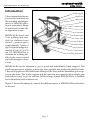
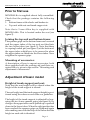
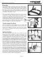
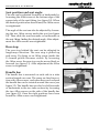
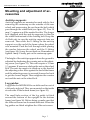
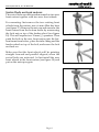
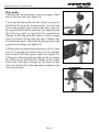
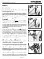
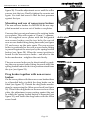
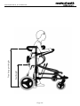
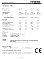
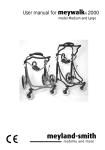
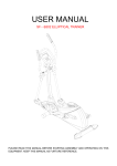
User manual for
miniwalk®
size 1 and size 2
meyland-smith
mobility and more
Page 2
www.meyland-smith.dk Tel: +45 98 96 19 85
Introduction
Trunk support
These instructions for use
contain information on
the assembly and adjustment of MINIWALK ®,
how to maintain it, things
to watch out for and other important issues
MINIWALK® Size 1 and
2 are walking aids suitable for children from
about 1½ years of age to
approximately 7 years of
age, height from approximately 65 cm (26") to 125
cm (49"). MINIWALK® is
intented for walking disabled who cannot stand
up without support from
a seat.
Handle bar
Upper tube
Ruler
Rear stop
Cone
Seat tube
Spanner grip
Lower tube
Brake
Rear wheel
Front bar
Fender wheel
Swivelling front wheel
Figure 1
MINIWALK® can be adjusted to give a good and individually fitted support. The
trunk support gives support to keep the torso upright and makes the child feel safe.
The rear stop prevent the child from sliding off the seat, and the handlebar gives support to the arms. The trunk support and the rear stop are opened with a simple grip
and makes it easy to get in and out. With its large wheels MINIWALK® is suitable
for both indoors and outdoors use.
Figure 1 shows the names of some of the different parts of MINIWALK® referred to
in the text.
Page 3
www.meyland-smith.dk Tel: +45 98 96 19 85
Prior to first use
MINIWALK® is supplied almost fully assembled.
Check that the package contains the following
parts:
• Bottom frame with wheels and brakes etc.
• Top unit with seat and trunk support etc.
Note that a 5 mm Allen key is supplied with
MINIWALK®. This is located under the seat (see
figure 2).
Figure 2
Joining the top unit and bottom frame:
The spanner grips on the bottom frame are loosened
and the upper tubes of the top unit are fitted into
the two lower tubes (see figure 3). Note that there
is a spring loaded pin (see figure 5) at the bottom of
the upper tubes which have to be pressed in when
the upper tubes are fitted into the lower tubes. Now
retighten the spanner grips.
Figure 3
Mounting of accessories:
A description of how to mount accessories, both
those supplied with the walking aid and those acquired later, is given in the section: “Mounting and
adjustment of accessories”.
Adjustment of basic model
Height of trunk support and seat:
Note that the seat height will be altered when the
height of the trunk support is altered.
Figure 4
The seat height and the trunk support height is positioned using the rulers on each side as a guideline.
The height of the trunk support is adjusted by loosening the two lower spanner grips (see figure 4). By
doing so the upper tubes can be pulled up or pushed
down in the lower tubes. When the right position has
been reached the spanner grips are tightened again
after making sure with the help of the rulers that the
height on each side is identical.
Page 4
Figure 5
www.meyland-smith.dk Tel: +45 98 96 19 85
Warning:
The upper tubes with the rulers are fitted with a
safety-stop. When the spring loaded pin (see figure
5) at the bottom of both of the upper tubes locks in
the hole in the lower tubes it marks the maximum
top unit height allowed. This marking may not be
exceeded - for safety’s sake!
The seat height is adjusted in the same way by loosening the two upper spanner grips (see figure 4). By
doing so the seat tube can be moved up or down the
upper tubes. When the right position has been
reached the spanner grips are tightened again
after making sure with the help of the rulers
that the height on each side is identical.
Figure 6
Trunk support locking:
When closing the trunk support one can “lock” the
two rear tubes by giving them a firm push downwards (see figure 6). In this way one can secure
them from accidently slide open or being opened
by “a busybody”!
Figure 7
Spring loading:
The two springs inside the lower tubes can be
replaced to give a harder or softer suspension. As
a guideline, it should be possible to collapse the
springs completely with the weight of the user. There
are three different spring hardnesses available, corresponding to the following minimum body weights:
green springs for at least 10 kg (22 lb.), silver springs for
at least 15 kg (33 lb.) and black springs for at least 20 kg
(44 lb.). To replace the springs the tilt bar is unscrewed
from the tubes on each side (see figure 7). The tilt bar
is moved away and the whole top unit is lifted off
the bottom frame (see figure 8). The bottom frame is
then turned around to enable the springs to fall out
(see figure 9). The springs are replaced while making
sure that they are positioned centrally over the inner
centertubes at the bottom of the lower tubes. Finally,
the top unit is placed back in the bottom frame and
the tilt bar is put in place and fastened.
Page 5
Figure 8
Figure 9
www.meyland-smith.dk Tel: +45 98 96 19 85
Seat position and seat angle:
The seat can be adjusted forwards or backwards by
loosening the Allen screw at the bottom edge of the
square tube of the seat fitting (see figure 10). When
the desired position has been found, the Allen screw
is retightened.
The angle of the seat can also be adjusted by loosening the two Allen screws under the seat (see figure
10). Then slide the seat forwards or backwards on
the seat fitting finding the desired angle. After adjustment the Allen screws are retightened.
Figure 10
Rear stop:
The rear stop behind the seat can be adjusted in
lengthways direction. The rear stop is pulled up
and away. By doing so an Allen screw inside the
U-formed profile becomes visible. By loosening
the Allen screw the rear stop can be moved back or
forward (see figure 11). After adjustment the Allen
screw is retightened.
Figure 11
Handle bar:
The handle bar is mounted on each side in a tube
section located on a cone. The cones are fixed in position with Allen screws, and when these are loosened
the handle bar can be rotated around the cones (see
figure 12). The handle bar can also be slid forwards
or backwards in the two tube sections by loosening
the two Allen screws on the side of the handle bar
(see figure 12). Once the right positions have been
found the Allen screws are retightened.
Page 6
Figure 12
www.meyland-smith.dk Tel: +45 98 96 19 85
Mounting and adjustment of accessories
Anti-tip supports:
Anti-tip supports are mounted on each side by first
removing the centercap on the outside of the rear
wheel and unscrewing the nut from the bolt which
pass through the wheel hub (see figure 13). Two 19
mm (¾") spanners will be needed for this. The longer
bolt supplied with the anti-tip supports is fitted in
the wheel hub instead of the existing bolt. Keep the
old bolt safe in case the anti-tip supports later are
removed. Then slide the U-fitting on the anti-tip
support over the end of the frame where the wheel
was mounted. Push the bolt through while placing
the washer between the wheel and the U-fitting
(see figure 14). Screw the nut back on. Remember to
tighten firmly. Finally put on the centercap again.
Figure 13
The height of the anti-tip supports from the ground is
adjusted by slackening the counter nut on the adjusting screw (see figure 13). This will require a 13 mm
(½") spanner. If necessary slacken the nut on the wheel
bolt. The anti-tip support is tilted up so the head of
the adjusting screw rests against the end of the frame
and the adjusting screw is screwed forward or back
to get the correct height. Then retighten the counter
nut and the nut on the wheel bolt.
Figure 14
Leg guides:
Figure 15
Leg guides for MINIWALK® are delivered in a set of
a left and a right rail. They are mounted on the inside
at each side of the bottom frame (see figure 15).
The small tube section of the leg guide is fitted
around the bottom of the upright on the bottom
frame (see figure 16). Before doing so make sure that
the Allen set screws are loosened sufficient. When the
leg guides are fitted retighten the Allen set screws.
Figure 16
Page 7
www.meyland-smith.dk Tel: +45 98 96 19 85
Swivel lock on front casters:
The swivel locks are delievered mounted on two new
front casters together with two new front wheels.
For mounting first remove the two existing front
wheels from the casters, use a 6 mm Allen key here
(see figure 17). Remove the nut-cap and unscrew the
front casters from the bottom frame by unscrewing
the lock nut on top of the fender wheel (see figure
18). This will require two 19 mm (¾") spanners. Then
push the bolt on the new front casters into the bottom frame from below, place the tube fitting and the
fender wheel on top of the bolt, and screw the lock
nut back on.
Make sure that the front wheels will be pointing
straight forward and parallel aligned, when the
swivel locks are activated. At last install the new
front wheels in the front casters (see figure 19) and
put on the nut-caps again.
Figure 17
Figure 18
Figure 19
Page 8
www.meyland-smith.dk Tel: +45 98 96 19 85
Hip-pads:
The hip-pads are mounted on the two upper tubes
below the seat tube (see figure 21).
To mount the hip-pads first lift off the top part of
MINIWALK® from the bottom frame. At each side
loosen the spanner grip on the lower tubes, press in
the spring loaded pin at each side (see figure 5) and
lift off the top unit (see figure 20). The spanner box
fittings for the hip-pads are slid in over the upper
tubes (see figure 20) and the top unit is fitted in the
bottom frame again. Then silde the hip-pads into the
spanner box fittings (see figure 21).
The hip-pads are adjusted away from or closer to the
seat by loosening the hand screws on the spanner
boxes which hold the square tubes (see figure 21).
The height of the hip-pads are adjusted by loosening
the Allen screws that hold the fittings on the upper
tubes and slide these fittings up og down on the
tubes (see figure 22). After adjustment retighten the
screws and grips.
Figure 20
Figure 21
Figure 22
Page 9
www.meyland-smith.dk Tel: +45 98 96 19 85
Brakes
Use of brakes:
The brakes are parking brakes which function by
directly blocking the rear wheels with a fitting that
presses against the tyre.
To brake the walking aid pull the brake levers all
the way back until they come to a definite stop (see
figure 23). In this position the brakes are self-locking.
The brakes are released by pushing the brake levers
forward again (see figure 24).
Figure 23
Warning:
Please note that the brakes cannot be adjusted ! This
is a deliberate choice of the manufacturer, since the
MINIWALK® uses solid rubber tyres with low wear
and tear. Should the walking aid suffer from reduced
braking ability after a long period of usage the rear
wheels and brake pads must be replaced.
Warning:
Please note that the brake levers are not intended to
be used by the child. This is a deliberate choice of
the manufacturer, since the brakes on MINIWALK®
are parking brakes and not driving brakes. In addition, the user of MINIWALK® is typically not able
to control the application of the brakes himself. If
required, however, it is possible on request to order
longer brake levers as an accessory.
Mounting and use of drag brakes:
The drag brakes for MINIWALK ® are supplied
mounted on a new set of brake cover plates.
Figure 24
Figure 25
Unscrew the two nuts and remove the existing brake
cover plates (see figure 25). This will require a 13 mm
(½") spanner. Fit the supplied cover plates with the
integrated drag brakes over the two bolts, the roller
facing bacwards and down (see figure 26) and screw
up the nuts again.
The drag brakes act on the rear wheel by the roller at
the back pressing into the tyre. First slacken off the
counter nut on the adjustment screw at the top (see
Page 10
Figure 26
www.meyland-smith.dk Tel: +45 98 96 19 85
figure 26). Turn the adjustment screw until the roller
presses into the tyre. Finally tighten the counter nut
again. Use trial and error to find the best pressure
against the tyre.
Mounting and use of non-reverse brakes:
The non-reverse brakes for MINIWALK® are supplied mounted on a new set of brake cover plates.
Unscrew the two nuts and remove the existing brake
cover plates. This will require a 13 mm (½") spanner.
Fit the supplied cover plates with the integrated
non-reverse brakes over the two bolts, the curved
non-reverse brake fitting facing bacwards (see figure
27) and screw up the nuts again. The non-reverse
brake is positioned so the non reverse brake fitting
is pressed against the rear tyre by the spring loaded
button (see figure 28). When the correct position is
found for the non-reverse brake - and also for the
brake mechanism - retighten the nuts firmly.
Figure 27
The non-reverse brake can be deactivated by pushing the non-reverse brake fitting forwards until the
spring loaded button locks it in a position raised from
the tyre (see figure 29).
Deactivated
Activated
Figure 28
Drag brakes together with non-reverse
brakes:
On the cover plates with the non-reverse brakes there
is a threaded hole at which the drag brake can be
fitted (see figure 27). Detach the drag brake mechanism by unscrewing the Allen screw head (see figure
26). Then fit the drag brake on the non-reverse cover
plate, the adjustment screw resting against the nut
in which the spring loaded button is mounted (see
figure 30), and fasten the drag brake with the Allen
screw head.
Figure 29
Figure 30
Page 11
www.meyland-smith.dk Tel: +45 98 96 19 85
Page 12
www.meyland-smith.dk Tel: +45 98 96 19 85
Safety precautions
Warning:
• MINIWALK® is a therapy product - and should only be used as such !
• The spring system used in MINIWALK® can involve a certain risk of the walking
aid toppling over if used by a very restless child.
• MINIWALK® rolls very easy, and one should always consider potetial dangers the
child can roll over to.
Therefore:
Never leave the child in MINIWALK® unatended !
Warning:
• If parts are removed, open tube ends may be revealed. These may have sharp inner
edges and be dangerous for probing fingers. MINIWALK® is designed to avoid the
necessity for open tube ends! If, however, a situation with open tube ends should
arise, it is recommended that they are sealed off with plastic plugs.
Limitations on use:
• The maximum user weight permitted is 40 kg (90 lb.).
• The walking aid should only be used on flat, level and stable surfaces.
Maintenance
The walking aid can be washed down with hot water and a normal detergent. However, the padding on the trunk support, handle bar and rear stop should be avoided.
With repeated use of detergent the painted frame may gradually take on a matt appearance, but can then be polished with car polish. Follow the instructions on the polish.
Checking for tightness:
Regularly check that all grips, bolts, screws and nuts are fully tightened and if
necessary retighten.
Oiling of springs:
Should the springs of MINIWALK® start to creak it
is possible to oil them from the bottom of the lower
tubes. The walking aid is turned upside-down and
very little oil is dripped into the two vents closest to
the center (see figure 31). The walking aid is left in
this position for a couple of minuts to enable the oil
to disperse. Then the walking aid is turned around
to its original position and it is left to drip off on a Figure 31
newspaper or the like.
Page 13
Seat height
Trunk support height
www.meyland-smith.dk Tel: +45 98 96 19 85
Page 14
www.meyland-smith.dk Tel: +45 98 96 19 85
Technical data
Dimensions:
Length:
External width:
Internal width:
Seat height:
Trunk support height:
Trunk support options
(chest measurement):
Weight:
MINIWALK® basic model:
Anti-tip supports (set):
Leg guides (set):
Swivel locks, fitted on
new front casters (set):
Hip-pads (set):
Drag brakes (set):
Non-reverse brakes (set):
Materials:
Frame:
Fittings:
Padding:
Seat cover:
Other:
Wheels:
Colours:
Size 1
74 cm
65 cm
39 cm
27 - 48 cm
52 - 75 cm
(29")
(25,5")
(15,5")
(10,5" - 19")
(20,5" - 29,5")
Size 2
74 cm
65 cm
39 cm
27 - 63 cm
67 - 90 cm
(29")
(25,5")
(15,5")
(10,5" - 25")
(26,5" - 35,5")
70 cm, 90 cm (27", 35")
70 cm, 90 cm (27", 35")
15 kg
1 kg
3 kg
(33 lb.)
(2 lb.)
(6 lb.)
15 kg
1 kg
3 kg
(33 lb.)
(2 lb.)
(6 lb.)
1 kg
1½ kg
½ kg
½ kg
(2 lb.)
(3 lb.)
(1 lb.)
(1 lb.)
1 kg
1½ kg
½ kg
½ kg
(2 lb.)
(3 lb.)
(1 lb.)
(1 lb.)
Powder-coated steel tubes
Electrolytically galvanized steel
Polyurethane foam
Synthetic leather
Soft solid rubber tyres on synthetic rims with self-lubricating
ball bearings
Turquoise, RAL 5021 / Red, RAL 3002
CE-marking
MINIWALK® is CE-marked. This warrants that MINIWALK® is
conforming to all relevant safety requirements in Council Directive
93/42/EEC concerning medical devices.
MINIWALK® is tested by Berlin Cert, Prüf- und Zertifizierstelle für
Medizinprodukte GmbH, an der Technischen Universität Berlin.
Page 15
Dealer:
Manufacturer:
meyland-smith
mobility and more
Industrivej 27 DK-9830 Taars
TEL. +45 98 96 19 85 • FAX +45 98 96 19 86
E-mail: [email protected]
Rev. MØC/101207