1
WebCCTV WebCCTV User Manual 2 Contents CONTENTS .................................................................................................................................................................................................................. 2 PREFACE ..................................................................................................................................................................................................................... 6 1 INTRODUCTION ........................................................................................................................................................................................... 7 2 GETTING STARTED .................................................................................................................................................................................... 9 2.1 2.2 2.3 2.4 2.5 3 WEBCCTV IIS SPLIT ...................................................................................................................................................................................... 9 ACCESS WEBCCTV VIA I NTERNET EXPLORER ........................................................................................................................................... 12 ACCESS WEBCCTV LOCALLY ...................................................................................................................................................................... 14 ADD WEBCCTV AS TRUSTED SITE ............................................................................................................................................................... 16 ADD WEBCCTV AS DEFAULT HOMEPAGE ................................................................................................................................................... 17 VIDEO MANAGER...................................................................................................................................................................................... 18 3.1 VIDEO MANAGER C ONTROL PANEL ............................................................................................................................................................. 18 3.2 USERS ............................................................................................................................................................................................................. 19 3.2.1 General Information ............................................................................................................................................................................. 19 3.2.1.1 The Operator/User Account ......................................................................................................................................................... 20 3.2.1.2 The Administrator Account ......................................................................................................................................................... 20 3.2.2 Users - Add New User .......................................................................................................................................................................... 21 3.2.3 Change Your Password ........................................................................................................................................................................ 23 3.2.4 User Actions Log................................................................................................................................................................................... 24 3.2.4.1 Log Search .................................................................................................................................................................................... 24 3.2.4.2 Event Logger Configuration ........................................................................................................................................................ 26 3.2.5 Connected Users ................................................................................................................................................................................... 26 3.3 SETTINGS ........................................................................................................................................................................................................ 28 3.3.1 Cameras................................................................................................................................................................................................. 29 3.3.1.1 Camera Search Wizard ................................................................................................................................................................. 30 3.3.1.1.1 IP Address ................................................................................................................................................................................. 31 3.3.1.1.2 Authentication .......................................................................................................................................................................... 31 3.3.1.2 Camera Wizard ............................................................................................................................................................................. 33 3.3.1.2.1 Name & Type ........................................................................................................................................................................... 33 3.3.1.2.2 Connection ................................................................................................................................................................................ 34 3.3.1.2.3 Live View ................................................................................................................................................................................. 35 3.3.1.2.4 Recordings ................................................................................................................................................................................ 36 3.3.1.2.5 Activity...................................................................................................................................................................................... 38 3.3.1.2.6 PTZ ............................................................................................................................................................................................ 40 3.3.1.2.7 Virtual Patrol ............................................................................................................................................................................ 41 3.3.1.2.8 Users .......................................................................................................................................................................................... 43 3.3.1.2.9 Audio ......................................................................................................................................................................................... 43 3.3.1.3 Network Video Server Wizard .................................................................................................................................................... 44 3.3.1.3.1 Name & Type ........................................................................................................................................................................... 45 3.3.1.3.2 Connection ................................................................................................................................................................................ 45 3.3.1.3.3 Video Settings........................................................................................................................................................................... 46 3.3.1.3.4 Name ......................................................................................................................................................................................... 46 3.3.1.3.5 Recordings ................................................................................................................................................................................ 47 3.3.1.3.6 Activity...................................................................................................................................................................................... 47 3.3.1.3.7 PTZ ............................................................................................................................................................................................ 49 3.3.1.3.8 Virtual Patrol ............................................................................................................................................................................ 50 3.3.1.3.9 Users .......................................................................................................................................................................................... 51 3.3.2 Alarms .................................................................................................................................................................................................... 52 3.3.2.1 Quadrox IO ..................................................................................................................................Error! Bookmark not defined. 3.3.2.1.1 Configuration ............................................................................................................................................................................ 53 3.3.2.1.2 Alarms ......................................................................................................................................Error! Bookmark not defined. 3.3.2.2 Quadrox USB I/O Device ............................................................................................................................................................ 56 3.3.2.2.1 Name ......................................................................................................................................................................................... 56 3.3.2.2.2 Configuration ............................................................................................................................................................................ 57 3.3.2.2.3 Outputs ...................................................................................................................................................................................... 58 3.3.2.2.4 Delete Quadrox USB I/O Device ............................................................................................................................................ 59 3.3.2.2.5 Quadrox USB I/O serial number ............................................................................................................................................. 59 Version 5.4 Series WebCCTV User Manual 3 3.3.2.3 Generic Alarm Driver................................................................................................................................................................... 60 3.3.2.3.1 Name ......................................................................................................................................................................................... 60 3.3.2.3.2 Protocol ..................................................................................................................................................................................... 61 3.3.2.3.3 Connection ................................................................................................................................................................................ 61 3.3.2.4 RedLight Alarm Driver ................................................................................................................................................................ 61 3.3.2.4.1 Name ......................................................................................................................................................................................... 62 3.3.2.4.2 Protocol ..................................................................................................................................................................................... 62 3.3.2.4.3 Connection ................................................................................................................................................................................ 62 3.3.2.5 Alarm Configuration Wizard ....................................................................................................................................................... 63 3.3.2.5.1 Name ......................................................................................................................................................................................... 63 3.3.2.5.2 PTZ ............................................................................................................................................................................................ 64 3.3.2.5.3 Recordings ................................................................................................................................................................................ 65 3.3.2.5.4 FTP ............................................................................................................................................................................................ 66 3.3.2.5.5 Outputs ...................................................................................................................................................................................... 66 3.3.2.5.6 Notification ............................................................................................................................................................................... 67 3.3.2.5.7 Mail ........................................................................................................................................................................................... 68 3.3.2.5.8 SMS ........................................................................................................................................................................................... 68 3.3.3 POS ........................................................................................................................................................................................................ 70 3.3.3.1 Serial Port POS ............................................................................................................................................................................. 71 3.3.3.1.1 Device Name ............................................................................................................................................................................ 72 3.3.3.1.2 Device Protocol ........................................................................................................................................................................ 72 3.3.3.1.3 Device Connection ................................................................................................................................................................... 72 3.3.3.1.4 POS Name................................................................................................................................................................................. 73 3.3.3.1.5 POS Recordings........................................................................................................................................................................ 73 3.3.3.2 Generic POS ................................................................................................................................................................................. 74 3.3.3.2.1 Device Name ............................................................................................................................................................................ 75 3.3.3.2.2 Device Protocol ....................................................................................................................................................................... 75 3.3.3.2.3 Device Connection ................................................................................................................................................................... 75 3.3.3.2.4 POS Name................................................................................................................................................................................. 76 3.3.3.2.5 POS Recordings........................................................................................................................................................................ 76 3.3.3.3 TP.Net ........................................................................................................................................................................................... 77 3.3.3.3.1 Device Name ............................................................................................................................................................................ 78 3.3.3.3.2 Device Protocol ........................................................................................................................................................................ 78 3.3.3.3.3 Device Connection ................................................................................................................................................................... 79 3.3.3.3.4 POS Name................................................................................................................................................................................. 79 3.3.3.3.5 POS Recordings........................................................................................................................................................................ 80 3.3.3.4 NAMOS ........................................................................................................................................................................................ 81 3.3.3.4.1 Device Name ............................................................................................................................................................................ 81 3.3.3.4.2 Device Protocol ........................................................................................................................................................................ 81 3.3.3.4.3 Device Connection ................................................................................................................................................................... 82 3.3.3.4.4 POS Name................................................................................................................................................................................ 82 3.3.3.4.5 POS Recordings........................................................................................................................................................................ 83 3.3.3.5 Quadrox POS Printer .................................................................................................................................................................... 84 3.3.3.5.1 Device Name ............................................................................................................................................................................ 85 3.3.3.5.2 Device Protocol ........................................................................................................................................................................ 85 3.3.3.5.3 Device Connection ................................................................................................................................................................... 85 3.3.3.5.4 POS Name................................................................................................................................................................................. 86 3.3.3.5.5 POS Recordings........................................................................................................................................................................ 86 3.3.4 Storage Manager .................................................................................................................................................................................. 88 3.3.4.1 Adding, configuring & deleting a Volume ................................................................................................................................. 88 3.3.4.1.1 Location .................................................................................................................................................................................... 89 3.3.4.1.2 Cameras..................................................................................................................................................................................... 90 3.3.4.1.3 Storage Parameters ................................................................................................................................................................... 90 3.3.4.2 Advanced Storage Settings .......................................................................................................................................................... 92 3.3.4.2.1 Movie Lifetime ......................................................................................................................................................................... 92 3.3.4.2.2 Alarms ....................................................................................................................................................................................... 92 3.3.4.2.3 POS............................................................................................................................................................................................ 93 3.3.4.3 Detailed Storage Information ...................................................................................................................................................... 94 3.3.5 Single View ............................................................................................................................................................................................ 96 3.3.5.1 Frame rate ..................................................................................................................................................................................... 96 3.3.5.2 Sequence ....................................................................................................................................................................................... 96 3.3.6 Mosaics .................................................................................................................................................................................................. 98 Version 5.4 Series WebCCTV User Manual 4 3.3.7 Web Publishing ................................................................................................................................................................................... 100 3.3.8 Network Settings ................................................................................................................................................................................. 101 3.3.9 Network Video Recorders................................................................................................................................................................... 102 3.3.9.1 Network Video Recorder Wizard .............................................................................................................................................. 102 3.3.10 Certificate Management ..................................................................................................................................................................... 104 3.3.10.1 Self-signed certificates ............................................................................................................................................................... 104 3.3.10.2 CA signed certificates ................................................................................................................................................................ 105 3.4 INFO .............................................................................................................................................................................................................. 106 3.4.1 System Info .......................................................................................................................................................................................... 106 3.4.1.1 System Configuration ................................................................................................................................................................. 107 3.4.1.1.1 Saving Configuration ............................................................................................................................................................. 107 3.4.1.1.2 Restoring Configuration......................................................................................................................................................... 107 3.4.1.2 System Information .................................................................................................................................................................... 108 3.4.2 Network Diagnostics........................................................................................................................................................................... 109 3.4.2.1 Port Scanning .............................................................................................................................................................................. 110 3.4.2.2 Camera Scanning ........................................................................................................................................................................ 110 3.4.3 Load ..................................................................................................................................................................................................... 111 3.4.4 Server Messages Log .......................................................................................................................................................................... 112 3.4.4.1 Log Search .................................................................................................................................................................................. 112 3.4.4.2 Event Logger Configuration ...................................................................................................................................................... 114 3.4.5 System Downloads .............................................................................................................................................................................. 115 4 VIDEO BROWSER .................................................................................................................................................................................... 116 4.1 VIDEO BROWSER CONTROL PANEL ............................................................................................................................................................ 116 4.2 LIVE .............................................................................................................................................................................................................. 117 4.2.1 Single View .......................................................................................................................................................................................... 118 4.2.1.1 Sequences .................................................................................................................................................................................... 119 4.2.1.2 Mosaics ....................................................................................................................................................................................... 119 4.2.1.3 Low/High Bandwidth Mode ...................................................................................................................................................... 120 4.2.1.4 Snapshots .................................................................................................................................................................................... 120 4.2.1.5 PTZ .............................................................................................................................................................................................. 120 4.2.1.6 Digital Zoom ............................................................................................................................................................................... 121 4.2.1.7 Audio ........................................................................................................................................................................................... 122 4.2.1.8 Quick Playback ........................................................................................................................................................................... 123 4.2.1.9 Full Screen Mode ....................................................................................................................................................................... 123 4.2.2 Mosaic View ........................................................................................................................................................................................ 124 4.2.2.1 Sequences .................................................................................................................................................................................... 124 4.2.2.2 Mosaics ....................................................................................................................................................................................... 125 4.3 RECORDINGS ................................................................................................................................................................................................ 126 4.3.1 Select Time Period .............................................................................................................................................................................. 127 4.3.2 Single Playback ................................................................................................................................................................................... 128 4.3.2.1 Single Playback Controls ........................................................................................................................................................... 129 4.3.2.2 Switching sources ....................................................................................................................................................................... 129 4.3.2.3 Activity Level ............................................................................................................................................................................. 129 4.3.2.4 Slider ........................................................................................................................................................................................... 129 4.3.2.5 Full Screen Mode ....................................................................................................................................................................... 129 4.3.2.6 Low/High Bandwidth Mode ...................................................................................................................................................... 130 4.3.2.7 Snapshots .................................................................................................................................................................................... 130 4.3.2.8 Digital Zoom ............................................................................................................................................................................... 131 4.3.3 Synchronized Playback....................................................................................................................................................................... 131 4.3.3.1 Synchronized Playback Controls ............................................................................................................................................... 132 4.3.3.2 Switching sources ....................................................................................................................................................................... 133 4.3.3.3 Slider ........................................................................................................................................................................................... 133 4.3.3.4 Full Screen Mode ....................................................................................................................................................................... 133 4.3.4 Smart Search ....................................................................................................................................................................................... 134 4.3.4.1 Smart Search Interface ............................................................................................................................................................... 134 4.3.4.2 Smart Search Playback Controls ............................................................................................................................................... 137 4.3.4.3 Full Screen Mode ....................................................................................................................................................................... 138 4.3.4.4 Low/High Bandwidth Mode ...................................................................................................................................................... 138 4.3.4.5 Snapshots .................................................................................................................................................................................... 139 4.3.4.6 Digital Zoom ............................................................................................................................................................................... 139 4.3.5 Movie Export ....................................................................................................................................................................................... 139 Version 5.4 Series WebCCTV User Manual 5 4.3.5.1 Creating Export........................................................................................................................................................................... 140 4.3.5.2 Saving Export Files to Hard Disk .............................................................................................................................................. 140 4.3.5.3 Saving Export Files to CD ......................................................................................................................................................... 141 4.3.5.4 Checking Digital Signature ........................................................................................................................................................ 143 4.3.6 Alarms .................................................................................................................................................................................................. 149 4.3.7 POS ...................................................................................................................................................................................................... 150 4.4 ALARMS ....................................................................................................................................................................................................... 151 4.4.1 View Alarm Movie .............................................................................................................................................................................. 152 4.4.2 Export Alarm Movie ........................................................................................................................................................................... 152 4.4.3 Slider .................................................................................................................................................................................................... 152 4.4.4 Alarm Playback Controls ................................................................................................................................................................... 153 4.4.5 Low/High Bandwidth Mode ............................................................................................................................................................... 153 4.4.6 Snapshots ............................................................................................................................................................................................. 153 4.4.7 Digital Zoom ....................................................................................................................................................................................... 154 4.5 POS .............................................................................................................................................................................................................. 155 APPENDIX A ........................................................................................................................................................................................................... 156 APPENDIX B ........................................................................................................................................................................................................... 161 GLOSSARY .............................................................................................................................................................................................................. 166 Version 5.4 Series WebCCTV User Manual 6 Preface This document This manual is intended for administrators and operators of a WebCCTV Video Recorder and is applicable for WebCCTV software version 5.4 and higher. Safety Notices Please observe all safety notes and instructions carefully when using this product. Liability The information in this publication is believed to be accurate in all respects. Quadrox assumes no responsibility for incidental or consequential damages incurred directly or indirectly from errors, omissions or discrepancies in connection with the furnishing, performance or use of this manual. The information contained herein is subject to change without notice. Revisions or new editions to this publication may be issued to incorporate such changes. All rights reserved. Under the copyright laws, no part of this manual can be reproduced in any form without written permission of Quadrox. Legal considerations Please check your local regional laws and regulations before using WebCCTV for surveillance purposes. Camera surveillance maybe prohibited by laws, which may vary from country to country. Trademark Acknowledgments Quadrox, WebCCTV, Internet Explorer, Windows are registered trademarks of the respective holders. Support Services Should you require any technical assistance, please contact your installer. If your questions cannot be answered immediately, your installer will forward your queries through the appropriate channels to ensure a fast response. Version 5.4 Series WebCCTV User Manual 7 1 Introduction WebCCTV is a unique digital video surveillance solution, which combines three major functions in one Network Video Recorder (NVR) or Digital Video Recorder (DVR): local digital recording, multiplexing and simultaneous transmission of the video via existing networks (TCP/IP). To a standard WebCCTV, up to 16 cameras can be permanently recorded while multiple operators at different locations on the network are accessing the WebCCTV device. Being a networked device, WebCCTV utilizes two basic principles of the Internet/Intranet technology: WebCCTV works over the TCP/IP network protocol, which provides maximum connectivity. This means that the existing computer network infrastructure can be used eliminating extra installation expenses. WebCCTV uses a web-based user interface to view live images, recordings, etc. More specific it uses Microsoft Internet Explorer. Remote and Local Monitoring To remotely monitor the connected cameras, the WebCCTV uses Web Browser technology. To locally monitor video, the WebCCTV also provides a local interface via a PC monitor directly connected to the WebCCTV. This local interface allows an operator to see live video from the connected cameras without the need for additional client computers on a network. Continuous Activity-Based Recording By default, a WebCCTV continuously records all images from all the connected cameras based on activity detection. In this case, only movement is recorded. If there is no movement, no recording takes place. If necessary, the WebCCTV can be set to record continuously. Intelligent Storage Option WebCCTV uses a first-in/first-out (FIFO) overwrite principle. Once the disk is full, the oldest images are overwritten. Semi-Continuous recording (recording based on activity detection) allows a WebCCTV to store pre- and post-alarm video. Pre- and Post-alarm images are often more important than the images at the time of the alarm event itself. Up to 5 minutes of pre- and post-alarm video can be stored. Version 5.4 Series WebCCTV User Manual 8 WebCCTV makes a distinction between common activity recordings and pre/post alarm recordings. In the way that, alarm recordings have a higher storage priority and will not be overwritten by non-alarm recordings. The WebCCTV is operational even when no live monitoring occurs. While the WebCCTV continuously records images from all the cameras, video is transmitted from the server to the client only when an Internet browser is connected to WebCCTV and someone is live-viewing images from one or more cameras. Version 5.4 Series WebCCTV User Manual 9 2 Getting Started This chapter provides information to get you started using your WebCCTV. It covers the following topics: Accessing WebCCTV via Internet Explorer. Accessing WebCCTV locally. Setting up WebCCTV application as default homepage. Add WebCCTV as a trusted site. 2.1 WebCCTV IIS Split As stated before, the WebCCTV application is a real web application which increases the flexibility and connectivity considerably. This web application is managed by IIS (Internet Information Services) which is installed on a computer of choice which can run IIS. Versions prior to version 4.0.8.0 only have the ability to install IIS on the Video Server itself. By having the option to install the web application (by using IIS) onto a computer of choice, it is possible to simplify the connection and scalability of the global security installation as the server itself and the web application don’t have to be installed on the same unit. In the beginning of the installation, you will be able to choose whether to use the split functionality or not. You must choose one of the options: typical or custom. The Typical (single server) option will install the web application and the video server on the same machine. Setup Type Selection Screen If Custom (multiple servers) is selected, there will be three possible options: Video Server with User Interface Server (default) – Both the video server and the web application will be installed on the unit. Option Typical (single server) or first option in the Custom menu. This is default installation and recommended if you have only one WebCCTV system. Version 5.4 Series WebCCTV User Manual 10 Video Server without User Interface Server – Only the Video Server is installed. This means you have installed the Web Application (User Interface) on another system. Option Custom (multiple severs). User Interface Server without Video Server – Only the Web Application is installed. Ideally this web application will be used as the central web application for all the WebCCTV systems in your network. Option Custom (multiple severs). You can choose one of the three options during the installation of your system by selecting Custom. Ask your installer for more information if you didn’t install the system yourself. Setup Type Selection Screen The following pictures give you an idea how it works: Centralized IIS Server on separate unit Version 5.4 Series WebCCTV User Manual 11 Centralized IIS Server on a Video Server Let us explain how this works in reality! If you have multiple Video Servers installed and have installed a centralized IIS server (On one of the Video Server or even on a separate PC), then you can connect to each Video Server by connecting first to the centralized Web Application by typing the IP of that unit. At that time you can choose which server you want to connect to in the network from the extended logon screen. In this case you only need to remember one IP address to connect to all your WebCCTV servers. This means that when you connect to a Video Server that also has the Web Application installed you will need the basic logon screen shown below: Basic Logon Screen Version 5.4 Series WebCCTV User Manual 12 If you want to connect through the centralized Web Server, you have to use the extend logon screen by clicking Options. There you select or type the video server IP or DNS name: For more information about the configuration of this setup, see chapter 3.3.7. Network Video Recorders where you can define all servers which are reachable through a centralized Web Server. You can choose which server you want to use as the default server to connect to. For more information, see chapter 3.3.7. Network Video Recorders. Extended Logon Screen 2.2 Access WebCCTV via Internet Explorer WebCCTV automatically starts recording the moment it is turned on and booted. The booting process takes about two minutes. The WebCCTV can be accessed via Internet Explorer. This Internet Explorer browser can reside on three places: 1. A capable client LAN PC: This is a PC in the same network as the WebCCTV 2. A capable client WAN PC: This is a PC on the wide area network. Your router/firewall has to be configured properly in order to connect to WebCCTV. 3. The WebCCTV: On the desktop of the WebCCTV, you can click the video browser icon which will open the Internet Explorer browser on the WebCCTV itself automatically redirecting you to the WebCCTV server. Only ‘ActiveX’ supporting Internet Browsers are designed to be used with the WebCCTV. Internet browsers like Netscape, Opera and other browsers that do not support ‘ActiveX’, are not suitable for use with WebCCTV. Version 5.4 Series WebCCTV User Manual 13 To access the WebCCTV server via Internet Explorer, follow the steps below: 1. Obtain the exact IP address for the WebCCTV from your System Administrator and make note of it for future reference. ‘http://192.168.100.1/’ is the factory default IP-address for a WebCCTV. Please note that your installer could have changed it to fit the specifications of your own network. 2. Open Internet Explorer. Click the Start button on your PC or WebCCTV and find Internet Explorer in the All Programs tab. An Internet Explorer link can often be found on the desktop. 3. Once Internet Explorer is opened, click on the address field and enter the IP-address as shown in the example below (without the quotes): ‘http://192.168.100.1/’ Make sure to include the http prefix into the IP-address. This is a protocol used for communication with a World Wide Web server. Since WebCCTV uses the same technology, the http prefix should be included. WebCCTV IP-address When you changed the TCP/IP communication port, you need to add the port in the IP-address. For example, is you changed the TCP/IP port to 81 (80 is default port), the IP-address becomes ‘http://192.168.100.1:81/’. If you want to connect to a WebCCTV or GuardDVR, your IP-address becomes ‘http://192.168.100.1/WebCCTV’ or ‘http://192.168.100.1/guarddvr’ If the WebCCTV is accessed for the first time with a client PC, you will need to install the ActiveX component. Follow the instructions on your screen. Installation of the component is done (semi) automatically on the first connection to a WebCCTV. The installation only has to be done once. Version 5.4 Series WebCCTV User Manual 14 2.3 Access WebCCTV locally The WebCCTV Local User Interface allows you to view video footage in real time by connecting a monitor directly to WebCCTV while recording at the same time. Compared to Internet Explorer access, accessing WebCCTV via the Local Interface has limited user functionality. The Local Interface access does not consume much CPU and memory. Accessing WebCCTV via Local Interface slightly increases image quality. To access WebCCTV locally, please follow the steps below: 1. Connect a monitor, a keyboard and a mouse directly to the WebCCTV. 2. By default, a standard Windows Login window will appear on the screen. Login with administrative credentials. Please contact your installer for the correct details. 3. Depending on how you accessed the WebCCTV last time, you will see either a WebCCTV Local Interface directly on the screen or a WebCCTV Local Interface icon on the system tray in the right bottom corner. 4. Double click the Local Interface icon to restore the Local Interface. It’s possible to configure the WebCCTV not to show the Windows logon screen after a restart and go directly to the Local Interface. To achieve this double-click the icon “Operator Mode” on the WebCCTV desktop. WebCCTV Local Interface Single View Screen Version 5.4 Series WebCCTV User Manual 15 WebCCTV Local Interface Mosaic View Screen WebCCTV Local Interface Control Panel WebCCTV Local Interface provides basic Live view functionality (in Single or Mosaic View). For complete WebCCTV functionality including settings, recordings, exporting, and accessing the WebCCTV server via Internet Explorer. WebCCTV Local Interface Buttons Single View Click on this button to access live view from a single camera. Mosaic View Click on this button to live view multiple cameras. Full Screen Button Click on this button to extend the application window to full screen view. Close Child Windows Button Click on this button to close all the windows on the screen Change Mosaic View Button This button is applicable only if more than 4 cameras are connected; it allows you to jump from one mosaic view to another. Version 5.4 Series WebCCTV User Manual 16 2.4 Add WebCCTV as trusted site The trusted sites zone contains sites you trust; sites that you believe you can download or run files from without worrying about damage to your computer or data. The default security level for the trusted sites zone is Low, therefore, Internet Explorer will allow all cookies and ActiveX controls from Web sites in this zone to be saved on your computer and read by the Web site that created them. We recommend adding WebCCTV to the trusted sites zone. To add the WebCCTV application as a trusted site, follow the steps below: 1. Select Tools on the Internet Explorer menu bar. 2. Select Internet Options. 3. Go to the Security tab. Select Trusted Sites there. Internet Options Screen Version 5.4 Series WebCCTV User Manual 17 4. Click the Sites button. In the window that appears deselect Require server verification (https:) for all sites in this zone check box. Trusted Sites Screen 5. Specify correct WebCCTV server address in the corresponding field and click Add button. 6. Address you specified appears in the Web sites filed. 7. Click OK. 2.5 Add WebCCTV as default homepage To make WebCCTV a default start page on a client PC, follow the steps below: 1. 2. 3. 4. Select Tools on the Internet Explorer menu bar. Select Internet Options. Select General. Click Use Current button or enter http://192.168.100.1 IP-address (or the correct WebCCTV IP-address) as your new default homepage. Version 5.4 Series WebCCTV User Manual 18 3 Video Manager To log on to the Video Manager application, you need administrative rights. This chapter provides an overview of the WebCCTV Video Manager Control Panel and the following WebCCTV functions: Users Server Settings General Server Information 3.1 Video Manager Control Panel Users Click this button to access the Users screens where you can add or delete users, give different user rights, check Connected Users and User Actions logs. Settings Click this button to change the WebCCTV settings to your requirements. Info Click this button to see general server information. This section also provides access to Network Diagnostics, System Downloads and the Server logs. Hide Control Panel Click this button to hide or retrieve the control panel. Restart Click this button to restart the video server. Usually there’s no need to restart the server unless the Restart button becomes red. Video Click this button to open the Video Browser application. Help Click this button to access WebCCTV Online help. Log Off Click this button to change user. Exit Click this button to exit the WebCCTV application. Version 5.4 Series WebCCTV User Manual 19 3.2 Users This chapter provides an overview of the Users section of WebCCTV. 3.2.1 General Information WebCCTV is a multi user system capable of supporting an unlimited number of users. Every registered user can have the following properties and user rights: Property Name Password Description Is used for the identification of the user Password related to the user for login Language Preferable language for the user Limitation Must be unique No limitation English, Dutch, French, Italian, German, Spanish, Russian, Ukrainian User Rights Live PTZ* Recordings Export Alarms POS User management** Description Access to live view Access to PTZ controls Access to view the recorded video footage Access to the export menu Access to view alarms and related video footage Access to view POS transactions and related video footage Access to change user privileges, view user actions log, view connected users System configuration** Access to modify system options * setting presets are only available to users with administrator rights ** only available to users with administrator rights Users with administrator rights can allow or block the viewing of certain cameras for non-administrative users. By default WebCCTV has two user accounts: Operator Account Administrator Account The default operator and administrator account can’t be deleted. WebCCTV Users management is fully integrated into the Windows Operating System users system, which results in very strong and safe access procedures. Version 5.4 Series WebCCTV User Manual 20 3.2.1.1 The Operator/User Account A non-administrative user can have different privileges and rights. He doesn’t have access to the video manager application. The default operator account can’t be deleted. 3.2.1.2 The Administrator Account A user with Administrator Rights can: Add new users Change passwords Delete users Set user privileges View User Actions Logs View Connected Users The default administrator account can’t be deleted. A User name cannot be changed once it has been added. It can only be deleted. The only parameters that can be changed are User Type, User Password, User Language and User privileges. Only an Administrator can grant, limit and edit user rights. The screen shown below is displayed when you click on the Users button (TEST09 here is the name of the PC; in new system it will be WEBCCTV): Users Screen Version 5.4 Series WebCCTV User Manual 21 The screen shown below is displayed with available Windows Users: Users Screen with Windows Users The subsections of the users menu are: Users Change Your Password User Actions Log Connected Users 3.2.2 Users - Add New User By clicking the Users button, you are automatically taken to the Users menu. Adding a user can be done in two ways: Add an existing Windows user or domain user: 1. Click the Show Windows Users button 2. Select the existing Windows or domain user in the right panel and click the left arrow. Your user is added as an Operator/User account. Click Edit. Go now to Step 3. Add a totally new user: 1. Click the Add New User button 2. Enter a Name. Go now to step 3. Version 5.4 Series WebCCTV User Manual 22 3. Enter a Password. If you added an existing user, the assigned default password is videouser. We strongly advise you to change the password. 4. Confirm the Password. 5. Select the interface language for the new user. 6. Define the ability for a user to change his password by (de)selecting the User cannot change password check box. 7. Select the Password never expires check box if you don’t want the password to expire. Otherwise a user will be forced to change the password every 6 weeks. General Screen 8. Select the privileges for the new user. Functionality Access Screen Version 5.4 Series WebCCTV User Manual 23 9. Define which cameras the user should be able to view on the Camera Access tab. Cameras Access Screen By default, a newly-added user has access to all the cameras. You cannot limit access to any functionalities and cameras for the user with Administrator rights. 10. Define the session parameters in the Sessions tab: Session expires – Time after which the user will be disconnected from the application. The user can login again afterwards. Time is measured in minutes. Limit concurrent number of sessions – Number of sessions the user can open simultaneously. Sessions Screen 11. Click Finish to apply the changes. 3.2.3 Change Your Password Changing your password from time to time helps to protect your system from unauthorized access. To change the password, follow the steps below: 1. 2. 3. 4. Enter the old password. Enter the new password. Enter the password confirmation. Click Apply. The new password should be set now. WebCCTV has no specific minimum password length limitation. When choosing a password, try to take a password of at least 8 characters and use both capital and small letters, both letters and figures or other characters (at least one of each). Version 5.4 Series WebCCTV User Manual 24 Change Your Password Screen Click on Cancel if you want to reset your form. 3.2.4 User Actions Log WebCCTV stores all user actions in its User Actions Log. Example of user actions are live views, recording views, user management changes, etc. This log is kept inside the Windows operating system itself. Technically, it is kept inside a specific WebCCTV event log container in the Windows event logging subsystem. The amount of logged user actions (number of days contained in the log) depends on the defined size of the event viewer. In normal circumstances, the log is large enough to keep WebCCTV user logs for approximately 60 days. 3.2.4.1 Log Search The search option allows you to retrieve all or specific actions that a certain user has performed. Log Search Screen Version 5.4 Series WebCCTV User Manual 25 All possible actions are described in the following table and can be found in the picture above. Category Security Streaming Recording View Export Description Activity of the user’s actions related to users management. Activity of the cameras that have been watched in live view. Activity of viewing video footage. Activity of video footage files that were made for exporting. To do a search, follow the steps below: 1. 2. 3. 4. Specify the user for which you want to search (Optional). Define the time frame in which you want to search. Check the required categories checkboxes. Click the Search button. The figure below provides a sample overview of a User Actions Log (Security, Streaming, Playback, Export): User Actions Logbook Screen User Actions Log allows you to check all user actions at all times. In order to conduct a new log search, click on the New search button. The reset filter button will clear all the checked boxes so that you can make a new selection. Version 5.4 Series WebCCTV User Manual 26 3.2.4.2 Event Logger Configuration The Event Logger Configuration defines the priority levels for the recorded events. Depending on the selected option, WebCCTV will or will not store certain events. Event Logger Configuration Screen There are three Recorded Events levels: Only Critical Events – WebCCTV stores the most important system events that occur when proper WebCCTV performance is impossible, e.g. recording break, failure to detect a system component, etc. Important Events – WebCCTV stores system events labelled as “Only Critical Events” and system events that play a significant role in the WebCCTV operating, e.g. playback stream creating, system logging on, etc. All Events – WebCCTV stores all system events. To apply new settings, click Apply. To cancel your changes, click Cancel. To go back to the Users Actions Log screen, click Return. Event Logger Settings functionality is unique for both User Actions Log and Server Actions Log. 3.2.5 Connected Users This screen enables you to observe specific information about connected users such as: User Name – Name of the connected user. Client IP Address – In the Client IP address column you can observe two parameters, which are separated by a colon. IP address is the IP address of the client computer from which a user is connected to the WebCCTV server. Port number is the TCP port of the client computer through which a user is connected to the WebCCTV server. Action – Click the Disconnect button to disconnect a user. You can’t disconnect your own administrator session. Version 5.4 Series WebCCTV User Manual Connected Users Screen In the Client IP address column you can observe two parameters, which are separated by a colon: IP address is the IP address of the client computer from which a user is connected to the WebCCTV server. Port number is the TCP port of the client computer from which a user is connected to the WebCCTV server. Click the Refresh button to update the Connected Users list. Version 5.4 Series 27 WebCCTV User Manual 28 3.3 Settings Settings Control Panel The System Settings enable the user to change the WebCCTV behavior and adapt it to the specific requirements. This chapter covers the following sections: Cameras Alarms POS Storage Manager Single View Mosaics Network Settings Certificate Management Time Synchronization Use System Settings with extreme caution, some of them can seriously affect the WebCCTV performance and even stop proper functioning of the system. Some of the System Settings require the WebCCTV to be rebooted for the settings to take effect. You will be informed to reboot the WebCCTV server by a red message on the screen. To restart the WebCCTV, click the Restart button which will turn red or click the Restart now link that appears at the end of the message. While restarting the server, you will get a message that the server is restarting. Once restarted, a successful reboot message will be displayed. Version 5.4 Series WebCCTV User Manual 29 3.3.1 Cameras The Cameras overview screen is automatically displayed, when entering Settings menu. The WebCCTV supports both Analogue and Network cameras. Analogue cameras can also be added and edited through a Network Video Server. To add a Network camera click the Add IP Camera and follow the on-screen instructions in the Camera Wizard (See 3.3.1.1 Camera Wizard). To add a Network Video Server click the Add Network Video Server and follow the onscreen instructions in the NVS Wizard (See 3.3.1.2 Network Video Server Wizard). To change Camera or Network Video Server settings, click the Edit button to enter the Camera or Network Video Server Wizard which will guide you through the setting process for that camera or network video server. To directly access a Network camera or a Network Video Server, click the Go to button. This function is available for IP-cameras only. To delete a Network camera, click the Delete button. To delete a Network Video Server, click the Delete button. To delete all IP devices, click the Delete All IP Devices button. Cameras Screen To disable or enable a camera click its number. The button will become red when the camera is disabled in the system. Version 5.4 Series WebCCTV User Manual 30 3.3.1.1 Camera Search Wizard To enter the Auto-configuration wizard, click the Add IP Camera Automatically button. The Camera Search screen will be opened and will start searching automatically for cameras in the Local Area Network (LAN). Following vendors are supported by Camera Search: Approtech: o All models supported. (See supported camera list for all models) Arecont: o All models supported. (See supported camera list for all models) o o o AXIS 2XX video products with firmware versions 4.03/4.10 or higher Exceptions: AXIS 205 / 230 / 250S / 262 / 292. AXIS 1XXX, 3XXX, PXXXX and QXXXX series Axis: IQEye: o o o o o IQEye Sentinel Series IQEye Alliance Series IQEye 700/750 Series IQEye 500 Series IQEye HD1080p Series Panasonic: o BL-C1 / 10 / 20 / 30 / 101 / 111 / 121 / 131 / 140 / 160 / 210 / 230 BB-HCM311 / 331 / 371 / 381 / 403 / 511 / 515 / 527 / 531 / 547 / 580 / 581 / 701 / 705 / 715 / 735 BB-HCE481 o All models supported. (See supported camera list for all models) o o Zavio: Cameras Search Screen To add a camera, specify the name you want to give to the camera (Optional), select the check box next to the camera and click the Add selected cameras button. You don’t have to wait till the search has stopped to start adding cameras. The Camera Auto Configuration Wizard will open and has the following tabs: IP Address Authentication Version 5.4 Series WebCCTV User Manual 31 3.3.1.1.1 IP Address In this screen you configure the Starting IP Address for the cameras you are adding. Depending on the network settings of your computer (Subnet Mask), fields will be disabled in order to enforce that the camera is added in the correct network. Each selected camera will be assigned a consecutive IP address, starting with the address which will be prompted. Only free addresses will be used. If the camera already has an IP address in the correct subnet, it will not be changed. IP Address Screen Click Next to enter the next Camera Search screen. 3.3.1.1.2 Authentication This screen allows you to enter the login credentials for your cameras. Select the radio button which is applicable for your cameras. There are two possibilities: Cameras with factory default settings – The cameras have factory default settings. Enter a password and confirm it. This password will be assigned to the Administrator account of the cameras. Cameras are pre-configured – The cameras have been configured in the past and are located in the correct network. Enter the user name and password that were used at that time. If preferred, you can assign a new password in the new password field, otherwise leave this field empty. Quadrox recommends using one password for all the cameras for your convenience. This might however affect security. If the password leaks, all cameras are compromised. If you want a fully secured video network, manually assign different passwords to every camera after completing this configuration. Version 5.4 Series WebCCTV User Manual 32 Authentication Screen Click Finish to add the cameras. A Camera Adding Result screen will open with the results and the server will restart automatically if necessary. To start a new search, click the New Camera Search button. Camera Adding Result Screen Click Cancel to go back to the Camera Search screen. You can always add cameras manually by clicking the Add IP Camera button in the Cameras Screen. Version 5.4 Series WebCCTV User Manual 33 3.3.1.2 Camera Wizard To enter the Camera Wizard click the Edit or the Add IP Camera button in the Cameras Screen. The Camera Wizard can consist of eight tabs with easy to follow instructions. Read this chapter to learn all about camera settings. The following Camera Wizard tabs are described in this chapter: Name & Type Connection Live view Recordings Activity PTZ Virtual Patrol Users By default, some of the settings are already selected. It is advisable to keep these settings to assure the best performance. Depending on the camera type (network or analogue) and camera model, some tabs may not be present or may be disabled. During the configuration, you may be asked to restart the server. This must be done first before finishing the configuration to assure the proper working of the WebCCTV server. 3.3.1.2.1 Name & Type In this screen, you define the camera name, type and model of the camera. Once the camera is added, you cannot change its type. Name & Type (Network camera) Screen Click Next to enter each camera and go to the next Camera Wizard screen. Version 5.4 Series WebCCTV User Manual 34 3.3.1.2.2 Connection This tab is only available for network cameras. If you are adding an analogue camera, this screen will not appear. This screen allows you to define the parameters needed for a network camera connection: Camera IP address or DNS name Port User name Password Delivery mode Multicast IP-Address Port To obtain these parameters, contact your system administrator or read the user manual of the camera itself. Use camera Administrator credentials in order to get all WebCCTV functionality. A DNS name is a meaningful and easy-to-remember "handle" for an Internet address or IP address. Connection (Network camera) Screen The delivery mode parameter is only available when the network camera supports MPEG streaming: Unicast – normal connection type of a camera. It is simple in organization and efficient when one connected client uses the camera. So if WebCCTV is the only user of the camera, please use this type. Version 5.4 Series WebCCTV User Manual 35 Multicast – this connection type is efficient when multiple applications use the cameras. This approach decreases the bandwidth usage. MPEG cameras allow sending the images to multicast IP addresses. These addresses are reserved in the IP protocol for multicast information distribution. To program a camera to send the images to a multicast address, you have to configure it in the camera’s native software software. Specify the IP address on the Connection Screen of the camera wizard. Multicast IP addresses are in the range 224.0.0.0 through 239.255.255.255. Click Next to enter the next Camera Wizard screen. 3.3.1.2.3 Live View The Live View tab will appear differently depending on whether you are viewing Analogue or IP cameras. The following parameters can be set for an analogue camera: Image resolution – as a rule of thumb, the higher the quality of the image (higher image resolution), the lower the frame rate you will have. Differential transmission – when differential transmission is enabled, only the differences between subsequent images are sent over the network. This feature drastically decreases the amount of transmitted video-data and is especially designed to be used when viewing camera images over the Internet. Live View (Analogue camera) Screen Version 5.4 Series WebCCTV User Manual 36 The following parameters can be set for a network camera: Format – gives an opportunity to choose between commonly used Compression technologies or indicates the compression technology that is used for a specific camera type. Image resolution – a higher resolution gives a better quality image. A higher image resolution will lead to a lower frame rate. Live View (Network camera) Screen Click Next to enter the next Camera Wizard screen. 3.3.1.2.4 Recordings The available parameters for recordings are the same for analogue and network cameras: Record this camera – the camera will be recorded if the box is checked. Format – gives the option to choose between commonly used compressions technologies or indicates the compression technology that is used for a specific camera type. Image resolution – a higher resolution gives a better quality image. A higher image resolution will lead to a lower frame rate. Frame rate – possible frame rates depend on the chosen image resolution. Volume – the storage volume on which the camera is recorded. You can change the volume for each camera (see 3.3.4 Storage Manager) Version 5.4 Series WebCCTV User Manual Recordings (Analogue and Network camera) Screen Click Next to enter the next Camera Wizard screen. Version 5.4 Series 37 WebCCTV User Manual 38 3.3.1.2.5 Activity By enabling activity detection, only images where movement is above a certain threshold will be recorded. This significantly increases the ability to store more video footage. If you want to record at all time, uncheck the Record only activity checkbox. If you use activity detection, you can always calculate activity on the server, but if the camera allows, you can configure the server to calculate activity on the camera instead of on the server: Server – When activity is calculated on the server, this will result in excellent recordings but introduces a higher load on the server. Furthermore you’re able to use the masking feature. By using the Masking feature, only activity in a specified area(s) will be recorded. This significantly increases the ability to store video footage. When adding a network camera, the Masking and Activity functionality is only available after a server restart. This will be requested automatically by a notification. The current activity level is represented by the green line on the control panel below the video. To adjust the activity detection threshold, move the slider on the right side of the control panel up and down to shift the red line. All the video activity that stays above the red line will be recorded. Activity on Server (Analogue and Network camera) Screen Masking makes it possible to disable the recording of activity in so called ‘curtain areas’. ‘Curtain areas’ contain constant movement classified as not important for surveillance (e.g. moving trees in the wind, ceiling fan etc.). The green grid, shown on the masking screen, divides the image into masking cells. Click on a cell and the activity detection in this cell will be disabled. Once disabled, a masking cell turns green. This means that activity occurring in this cell will not trigger recording. Version 5.4 Series WebCCTV User Manual 39 When you access the Activity screen for the first time on a client PC, it may be that the green masking grid doesn’t appear. In order to be able to draw the grid, the video card of the client PC has to have at least 16 MB of internal video memory and DirectX accelerations fully enabled. This can be done as follows: 1. Exit the camera wizard by clicking Finish or Cancel. 2. Go to Start/Settings/Control Panel. 3. Click on Display/ Settings/Advanced/Troubleshoot. 4. Set Hardware acceleration on full. Troubleshoot Screen Click OK and return to the Activity Screen in the Camera Wizard. The masking grid should be visible on your screen now. The masking functionality does not depend on whether you can visualize it on a particular client PC or not. It is possible to set up masking on one client PC and use another client PC which is not able to show masking. The masking will stay applied. To (un)mask the desired area, follow the steps below: 1. Click on the cell you wish to (un)mask. 2. Check the Mask or Unmask button depending on whether you want to mask or unmask. 3. Click the Apply mask button to activate the selection. To mask multiple cells, left-click one cell and drag the cursor over the cells you would like to mask and release your mouse. Click on the question mark icon in the right hand corner of the masking screen to access on-screen masking instructions. Click Next to enter the next Camera Wizard screen. Camera – When activity is calculated on the camera, this will result in acceptable recordings and a lower load on the server. The masking feature is disabled and has to be done on the camera. By default nothing has to be configured on the camera, nevertheless some models require configuration on the camera itself. See Appendix C for more information. Version 5.4 Series WebCCTV User Manual 40 Activity calculated on camera is supported for most models of the following brands: ACTi, Axis, Ernitec, IQEye. If activity is recorded or not depends on the camera activity detection algorithm. If you notice problems with recordings, please contact the camera manufacturer for support. Activity on Camera (Network camera) Screen Click Next to enter the next Camera Wizard screen. 3.3.1.2.6 PTZ This tab is present for both analogue and network PTZ cameras, however only analogue PTZ cameras can be configured PTZ stands for Pan Tilt Zoom, or a "movable" camera. To enable the PTZ camera settings, select the PTZ camera checkbox. PTZ camera – check this if your camera is a PTZ camera PTZ control protocol – select the brand of the PTZ camera Extended PTZ – Some protocols have extended PTZ features; e.g. Pelco. By checking this, these extended features will be made available. Communication port – serial communication port used for PTZ communication. Camera unique number – most PTZ cameras require a unique serial number to be referred by. Click Next to enter the next Camera Wizard screen. Version 5.4 Series WebCCTV User Manual 41 3.3.1.2.7 Virtual Patrol The Virtual Patrol screen allows you to configure a PTZ camera in several ways: Use Home preset – this functionality prevents the misplacement of the camera and ensures proper recordings after monitoring. If the Home Preset is enabled, the first preset position becomes automatically the Home status and looks like in the Live view. When a user moves the PTZ camera, by manual manipulation or using preset positions, the camera will return to its Home Preset after the assigned Recovery Time has elapsed. By default this time is 300 seconds. Use Virtual Patrol – select one of the Virtual Patrols you previously created. Manual PTZ Control – check this radio button if you don’t use either the Home Preset or the Virtual Patrol functionality. Virtual Patrol (Analogue and network camera) Screen Only specially designed cameras designated by the manufacturer as "Continuous movement use", "Continuous duty cycle" or "24h duty cycle" can effectively utilize the Virtual Patrol feature. Using consumer-grade cameras with Virtual Patrol may cause premature failure and may invalidate the cameras warranty. We strongly advise customers to check the camera specifications before using the Virtual Patrol feature and strongly advise setting the virtual patrol sequence time to a minimum of 120 seconds for those cameras. You can create multiple Virtual Patrols with different settings. Click the Add Virtual Patrol button to add a new Virtual Patrol. To change or create the Virtual Patrol settings, click the Edit link. Version 5.4 Series WebCCTV User Manual 42 Virtual Patrol Configuring Screen 1. Specify a Name for the Virtual Patrol 2. Choose one of the available Presets from the drop-down list and click Add Preset button. 3. Specify the Sequence time for every Preset. This is the time after which the camera is switched to the next defined preset in the queue. 4. If necessary, use the Sort buttons to change the position of a Preset in the Virtual Patrol sequence. 5. Click Apply button. You may delete any Preset from the Virtual Patrol sequence by clicking the Delete link. Due to some technology designs of Panasonic cameras, it is recommended to use no more than 2-3 Panasonic cameras with virtual patrol configured at the same time, since this can cause server overloading. Each time a user takes control over the PTZ camera manually (via the PTZ Camera Control Panel), the automatic Virtual Patrol is interrupted. Once the user stops his manual control, the WebCCTV resumes the Virtual Patrol after 30 seconds. Click Next to enter the next Camera Wizard screen. Version 5.4 Series WebCCTV User Manual 43 3.3.1.2.8 Users Select which users have access to the selected camera. The Users functionality is only available after you have added the camera, and restarted the server. Follow the notification that will automatically be shown. Users with Administrator rights have access to all cameras. Users with restricted rights can be denied access to certain cameras. Users (Analogue and network camera) Screen 3.3.1.2.9 Audio The audio tab is only available for network cameras that support audio. For more information about audio support, go to 4.2.1.10 Audio. This screen allows you to define the audio parameters for a network camera: Live audio – This enables live listen-in audio. External IP-address – Configure this if you want to enable remote live listen-in audio. Audio (Network camera) Screen Version 5.4 Series WebCCTV User Manual 44 3.3.1.3 Network Video Server Wizard In this manual, we will refer to a Network Video Server as NVS. To enter the Network Video Server Wizard, click the Edit device or Add Network Video Server link/button in the Cameras screen. The Network Video Server Wizard consists of three tabs with easy to follow instructions. The following Network Video Server Wizard tabs are described in this chapter: Name & Type Connection Video Settings If you need to change camera settings from cameras that are connected to the NVS, click the Edit link of the camera in the cameras screen which will display the Network Video Server Cameras Wizard. The Network Video Server Camera Wizard consists of six tabs with easy to follow instructions. The following Network Video Server Camera Wizard tabs are described in this chapter: Name Recordings Activity PTZ Virtual Patrol Users You need to install the Quadrox Codecs Pack for proper NVS usage. The NVS Wizard displays settings which are common for all cameras connected to the NVS. In the NVS Camera Wizard you are able to adjust the specific settings for an individual camera connected to the NVS. By default, some of the settings are already selected. It is recommended that you keep these settings to ensure the best performance. Cameras Screen Version 5.4 Series WebCCTV User Manual 45 3.3.1.3.1 Name & Type In this tab, you can adjust the NVS name, type and model. It’s a part of the Network Video Server Wizard. Choose a descriptive name for each NVS for easy future reference. Name & Type (Network Video Server) Screen Click Next to enter the next NVS Wizard screen. 3.3.1.3.2 Connection This tab allows you to define the parameters needed for the NVS connection. It’s a part of the Network Video Server Wizard: NVS IP address User name Password The Default Admin ID for the NVS400 series is ‘admin’ and the default Admin password is ‘pass’. For the NVS1000/2000/4000 series the Admin ID becomes ‘root’ and the default Admin password is ‘pass’. Connection (Network Video Server) Screen Click Next to enter the next NVS Wizard screen. Version 5.4 Series WebCCTV User Manual 46 3.3.1.3.3 Video Settings This tab is a part of the Network Video Server Wizard and allows configuring following settings: Video format – selection of the video standards format in which images are transmitted from the cameras. PAL video standard is used in Europe, NTSC video standard is used in the USA. Image resolution – a higher resolution gives a better quality image. A higher image resolution will lead to a lower frame rate. Frame rate – possible frame rates depend on the chosen image resolution. Volume – storage volume on which the camera is recorded. You can change the volume for each camera (see 3.3.4 Storage Manager) Settings you are adjusting in this screen are applied to all NVS cameras for live view and recordings. Video Settings (Network Video Server) Screen Complete the procedure by clicking Finish button and Restart the WebCCTV server. 3.3.1.3.4 Name This tab is a part of the Network Video Server Camera Wizard. You can assign a name to the camera in this screen. Name (Network Video Server) Screen Click Next to enter the next NVS Camera Wizard screen. Version 5.4 Series WebCCTV User Manual 47 3.3.1.3.5 Recordings This tab is a part of the Network Video Server Camera Wizard. The following parameters can be configured: Record this camera – the camera will be recorded if the box is checked. Volume – storage volume on which the camera is recorded. You can change the volume for each camera (see 3.3.4 Storage Manager) Recordings (Network Video Server) Screen Click Next to enter the next NVS Camera Wizard screen. 3.3.1.3.6 Activity This tab is a part of the Network Video Server Camera Wizard. The following parameters can be configured: When adding a NVS, the Masking and Activity functionality is only available after server restart. This will be automatically requested by a notification. Activity Detection – by enabling Activity Detection, only images where movement is above a certain threshold will be recorded. This increases the ability to store more video footage significantly. If you want to record all the time, uncheck the Record only activity checkbox. Activity (Network Video Server) Screen Version 5.4 Series WebCCTV User Manual 48 The current activity level is represented by the green line on the control panel below the video. To adjust the activity detection threshold, move the slider on the right side of the control panel up and down to shift the red line. All the video activity that stays above the red line will be recorded. Masking – by using the masking feature, only activity in a specified area(s) will be recorded. This increases the ability to store more video footage significantly. Calculate activity on – Each method of activity detection processing has advantages and disadvantages. Activity detection processing on the WebCCTV server allows detecting the activity using the best accuracy, but consumes more CPU resources. Activity detection processing on WebCCTV NVS consumes fewer CPU resources, but operates inaccurately in low light conditions. Masking makes it possible to disable the recording of activity in so called ‘curtain areas’. ‘Curtain areas’ contain constant movement classified as not important for surveillance (e.g. moving trees in the wind, busy parts of the road etc.). The green grid, shown on the masking screen, divides the image into masking cells. Click on a cell and the activity detection in this cell will be disabled. Once disabled, a masking cell turns green. This means that activity occurring in this cell will not trigger recording. When you access the Activity screen for the first time on a client PC, it may be that the green masking grid doesn’t appear. In order to be able to draw the grid, the video card of the client PC has to have at least 16 MB of internal video memory and DirectX accelerations fully enabled. This can be done as follows: 1. 2. 3. 4. Exit the camera wizard by clicking Finish or Cancel. Go to Start/Settings/Control Panel. Click on Display/ Settings/Advanced/Troubleshoot. Set Hardware acceleration on full. Troubleshoot Screen Click OK and return to the Activity Screen in the Camera Wizard. The masking grid should be visible on your screen now. Version 5.4 Series WebCCTV User Manual 49 The masking functionality does not depend on whether you can visualize it on a particular client PC or not. It is possible to set up masking on one client PC and use another client PC which is not able to show masking. The masking will stay applied. To (un)mask the desired area, follow the steps below: 1. Click on the cell you wish to (un)mask. 2. Check the Mask or Unmask button depending on whether you want to mask or unmask. 3. Click the Apply mask button to activate the selection. To mask multiple cells, left-click one cell and drag the cursor over the cells you would like to mask and release your mouse. Click on the question mark icon in the right hand corner of the masking screen to access on-screen masking instructions. Click Next to enter the next NVS Camera Wizard screen. 3.3.1.3.7 PTZ This tab is a part of the Network Video Server Camera Wizard. PTZ stands for Pan Tilt Zoom or movable camera. To enable PTZ camera settings, select the PTZ camera check box first. PTZ camera – select this if your camera is a PTZ camera. PTZ control protocol – select the brand of the PTZ camera. Extended PTZ – Some protocols have extended PTZ features, e.g. Pelco. By checking this, the features will be made available. Camera unique number – most PTZ cameras require a unique serial number to be referred by. PTZ (Network Video Server) Screen Click Next to enter the next NVS Camera Wizard screen. Version 5.4 Series WebCCTV User Manual 50 3.3.1.3.8 Virtual Patrol This tab is a part of the Network Video Server Camera Wizard. The Virtual Patrol screen allows you to configure a PTZ camera in several ways: Use Home preset – this functionality prevents the misplacement of the camera and ensures proper recordings after monitoring. If the Home Preset is enabled, the first preset position becomes automatically the Home status and looks like in the Live view. When a user moves the PTZ camera, by manual manipulation or using preset positions, the camera will return to its Home Preset after the assigned Recovery Time has elapsed. By default this time is 300 seconds. Use Virtual Patrol – select one of the Virtual Patrol you previously created. Manual PTZ Control – check this radio button if you don’t use either the Home Preset or the Virtual Patrol functionality. Virtual Patrol (Network Video Server) Screen Only specially designed cameras designated by the manufacturer as "Continuous movement use", "Continuous duty cycle" or "24h duty cycle" can effectively utilize the Virtual Patrol feature. Using consumer-grade cameras with Virtual Patrol may cause premature failure and may invalidate the cameras warranty. We strongly advise customers to check the camera specifications before using the Virtual Patrol feature and strongly advise to set the virtual patrol sequence time to a minimum of 120 seconds for those cameras. You can create multiple Virtual Patrols with different settings. Click the Add Virtual Patrol button to add a new Virtual Patrol. To change or create the Virtual Patrol settings, click the Edit link. Version 5.4 Series WebCCTV User Manual 51 Virtual Patrol Configuring Screen 1. Specify a Name for the Virtual Patrol 2. Choose one of the available Presets from the drop-down list and click Add Preset button. 3. Specify the Sequence time for each Preset. This is the time after which the camera switches to the next defined preset in the queue. 4. If necessary, use the Sort buttons to change the position of a Preset in the Virtual Patrol sequence. 5. Click Apply button. You may delete any Preset from the Virtual Patrol sequence by clicking the Delete link. Due to some technology designs of Panasonic cameras it is recommended you use no more than 2-3 Panasonic cameras with virtual patrol configured at the same time, since this can cause server overloading. Each time a user takes control over the PTZ camera manually (via the PTZ Camera Control Panel), the automatic Virtual Patrol is interrupted. Once the user stops his manual control, the WebCCTV resumes the Virtual Patrol after 30 seconds. Click Next to enter the next NVS Camera Wizard screen. 3.3.1.3.9 Users Select which users have access to the selected camera. The Users functionality is only available after server restart when adding a new NVS. Follow the notification that automatically will be shown. Users with Administrator rights have access to all the cameras. Users with restricted rights can be denied access to certain cameras. Users (Network Video Server) Screen Version 5.4 Series WebCCTV User Manual 52 3.3.2 Alarms The Alarms chapter covers the handling and configuration of incoming alarms, alarm reactions and how to configure the actions linked to these incoming alarm events. Input alarms can be generated through a physical alarm-input concentrator (screw-block to attach physical wires) attached on the back of the WebCCTV machine (together with a Picolo card), or through a Quadrox USB I/O Device (screw-block to attach physical wires) attached to the WebCCTV NVR via a USB cable. The WebCCTV Alarm Component supports the OPC protocol; hence you are able to connect any OPC A&E compliant alarm server and OPC A&E compliant client as well to the WebCCTV Alarm Component. The origin of an alarm input can be an external infrared sensor, a reed contact, etc. By default you get the alarms menu when clicking Alarms in the Settings menu. This menu allows you to Add Quadrox USB I/O Device, Add Alarm Device and access the Alarms Configuration Wizard by clicking Edit or Edit Device. This chapter covers the following topics: Quadrox IO device (Adding and Configuring) Quadrox USB I/O Device (Adding and Configuring) Generic Alarm Driver RedLight Driver Alarms Configuration Wizard Alarms Screen Version 5.4 Series WebCCTV User Manual 53 3.3.2.1 Quadrox IO device Quadrox IO is an universal hardware device specially designed for organizing Input\Output interaction with Quadrox WebCCTV and QGuard systems. Quadrox IO is equipped with 8 hardware inputs and 8 hardware outputs, which can be defined directly from the server’s web-interface. Our device uses an open hardware platform, containing RJ45 socket on board, which allows unit allocation on long distances. Quadrox IO is supported from server ver.5.0.0.0. The Alarm component must be installed on the server! Ask for updates here: [email protected] 3.3.2.1.1 Configuration Open WebCCTV (QGuard) Video Manager page, log in and go to the “Alarms” tab. Press “Add Quadrox IO” button. You will see the configuration Wizard: Device name: give a friendly name to your alarm device. IP-address or DNS name: provide here the IP address that you previously set up using the Quadrox IO configuration tool (see Quadrox IO manual for details). Port: the default value is 5000. Login: device login. Password: device password. After entering all data, press “Finish” button. Version 5.4 Series WebCCTV User Manual 54 You will see that your Quadrox IO appeared in the Alarms tab now: Now you have all 8 inputs (alarms) available to configure. They will all have standard names like: “Alarm [your_device_name] 1-1”. Click on the corresponding “Edit” button to configure the input. Here you can set inputs as well as any other regular alarms on server. If you need to configure a Quadrox IO output, you have to edit any present alarm device and move to the “Outputs” tab. Here you should choose a particular Quadrox IO output from the drop-down list, configure the rest of options and press the buttons “Add Output” and “Finish”. Version 5.4 Series WebCCTV User Manual 55 You can change the names of the outputs using the “Edit Device” option from the “Alarms” tab. Video Manager -> Settings -> Alarms Quadrox IO Edit device dialog -> Outputs tab Quadrox IO can be deleted from the server pressing the “Delete Device” link. 3.3.2.1.2 Alarms Once your inputs and\or outputs were configured, you are able to receive signals from external devices and send physical reactions as well. Let’s see how alarms received from Quadrox IO work at server side. When some of Quadrox IO’s inputs were closed, you will see an Event on “Alarms” page of Web Browser. “Alarms” button will blink with red until the alarm will be de-activated. Version 5.4 Series WebCCTV User Manual 56 3.3.2.2 Quadrox USB I/O Device The Quadrox USB I/O device has to be added manually. To do so, follow the steps below: 1. Attach the Quadrox USB I/O Device to one of the USB ports of your WebCCTV. Quadrox USB I/O Device supports USB 2.0. 2. Click Add PMD I/O Device button. Alarms (Quadrox USB I/O Device) Screen The Quadrox USB I/O Device Configuration Wizard will be opened for configuration. 3.3.2.2.1 Name This screen shows basic information about the I/O Device. It contains two fields: Device type – general information about the type of I/O Device connected. Serial Number – enter the serial number of your I/O Device in this field. To obtain the serial number of your Quadrox USB I/O Device, refer to USB I/O Device documentation or use the special tool that is located in the Support folder to set a new serial number. (see 3.3.2.2.5 Quadrox USB I/O Serial Number) Name (Quadrox USB I/O Device) Screen Click Next to enter the next I/O Device Configuration Wizard Screen. Version 5.4 Series WebCCTV User Manual 57 3.3.2.2.2 Configuration This screen allows you to configure your I/O Device lines as inputs or outputs for the alarm signals. Configuration (Quadrox USB I/O Device) Screen When the Quadrox USB I/O device is disconnected from the USB port and the server is restarting, the Quadrox USB device disappears from I/O Devices list. After being reconnected and subsequently restarting the server, it appears again. The Quadrox USB I/O device has 3 ports and each port has 8 lines, however one port is divided in two parts, where every subpart has 4 lines. This makes 24 lines in total. Compared to the Picolo I/O card, where every line can be configured separately, you need to configure a whole port as an input or output for the Quadrox USB I/O device. There are 4 drop-down lists and each of them corresponds to a certain port. Value I O Description Configure line as input. This line receives an alarm signal from an external device. Configure line as output. This line sends a control signal to the external device. Click Finish button. If you entered a correct Quadrox USB I/O Device serial number you should see the following screen: Version 5.4 Series WebCCTV User Manual 58 Alarms (Quadrox USB I/O Device Added) Screen Click Edit Device link. Go to the Outputs tab. 3.3.2.2.3 Outputs This screen allows you to assign names to the lines you have configured as outputs. The Outputs tab is not available in the WebCCTV Quadrox USB I/O Device Configuration Wizard when you are adding the Quadrox USB I/O Device. It becomes available after you add the device and click Edit Device link in the Alarms menu. Outputs (Quadrox USB I/O Device) Screen Click the Finish button to apply the configuration. Version 5.4 Series WebCCTV User Manual 3.3.2.2.4 Delete Quadrox USB I/O Device If you want to delete your Quadrox USB I/O Device, execute the following steps: 1. While being in Alarms Menu, click the Delete Device link. Alarms (Deleting Quadrox USB I/O Device) Screen 2. Click OK in the pop-up window. Confirmation (Deleting Quadrox USB I/O Device) Screen 3.3.2.2.5 Quadrox USB I/O serial number To assign the serial number to a Quadrox USB I/O Device, follow the steps below: 1. Connect your Quadrox USB I/O Device to the computer. 2. Go to C:\Program Files\Quadrox\, find pmdserialnumber.exe and click on it. 3. A command prompt will appear. Assigning Quadrox USB I/O Serial Number Screen 1 Version 5.4 Series 59 WebCCTV User Manual 60 4. Specify Y and click Enter button. 5. Please enter the new serial number message will appear on the screen, specify new serial number. Click Enter. Assigning Quadrox USB I/O Serial Number Screen 2 6. As prompted, press any key to finish assigning the Quadrox USB I/O Device serial number. 3.3.2.3 Generic Alarm Driver The Generic Alarm Driver makes it possible to generate alarms without needing a hardware device. Generating alarms is done by using the SDK (Software Development Kit). For more information about how to utilize the SDK Kit, contact [email protected]. To add the Generic Alarm Driver, click Add Alarm Device button. Alarms Screen The Alarm Configuration Wizard will be opened for configuration. 3.3.2.3.1 Name This tab allows you to specify the Device Name. Name (Generic Alarm Driver) Screen Click Next to enter the next Alarm Configuration Wizard Screen. Version 5.4 Series WebCCTV User Manual 61 3.3.2.3.2 Protocol In this tab, the protocol has to be selected Select Generic Alarm Driver in the drop-down list. Protocol (Generic Alarm Driver) Screen Click Finish button. Depending on the drivers you installed together with the Alarm Component, it’s possible some values are not present in the drop-down list. If you entered the Alarm Configuration Wizard by clicking the Edit Device link in the Alarms Screen, you can’t change the protocol anymore, but can only see which protocol has been selected. 3.3.2.3.3 Connection This tab is not available for the Generic Alarm Driver Device. You don’t have to configure it. 3.3.2.4 RedLight Alarm Driver The RedLight Alarm Driver makes it possible to receive alarms for Red Light infractions. This driver may and can only be used in cooperation with Quadrox N.V. For more information, contact [email protected]. You need extra add-on software to be able to receive alarms. To add the RedLight Alarm Driver, click Add Alarm Device button. Alarms Screen The Alarm Configuration Wizard will be opened for configuration. Version 5.4 Series WebCCTV User Manual 62 3.3.2.4.1 Name This tab allows you to specify the Device Name. Name (RedLight Alarm Driver) Screen Click Next to enter the next Alarm Configuration Wizard Screen. 3.3.2.4.2 Protocol In this tab, the protocol has to be selected Select RedLight Driver in the drop-down list. Protocol (RedLight Alarm Driver) Screen Click Next to enter the next Alarm Configuration Wizard Screen. Depending on the drivers you installed together with the Alarm Component, it’s possible some values are not present in the drop-down list. If you entered the Alarm Configuration Wizard by clicking the Edit Device link in the Alarms Screen, you can’t change the protocol anymore, but can only see which protocol has been selected. 3.3.2.4.3 Connection This tab allows for the configuration of the following settings: Dispatcher IP – IP address of the sender of the alarm events. Dispatcher Port – port used by dispatcher to send alarm events. Client IP – IP address of the client which accepts the alarm events. Basically this should be the WebCCTV server IP Address. Client Port – port used by client to receive alarm events. Client Name – unique name which identifies the client machine. Version 5.4 Series WebCCTV User Manual 63 Connection (RedLight Alarm Driver) Screen 3.3.2.5 Alarm Configuration Wizard To enter the Alarm Configuration Wizard in order to configure the alarms itself, click one of the Edit links in the Alarms Menu. The Alarm Configuration Wizard consists of eight tabs with easy to follow instructions. Read this chapter to learn all about the alarms configuration. The following Alarm Configuration Wizard tabs are described in this chapter: Name PTZ Recordings FTP Outputs Notification Mail SMS By default, some of the settings are already selected. It is recommended you keep these settings to ensure the best performance. When configuring a hybrid WebCCTV, you are able to use 13 Input/Output lines (for Q16 model – 26 I/O lines if 2 Picolo Tetra cards are used) by means of Picolo I/O Proxy. A Quadrox USB I/O Device gives you the ability to use 24 Input/Output lines. WebCCTV’s manufactured after 2007 may be a different type of capture card on which I/O is not supported. Use a Quadrox USB I/O Device in this case. A Quadrox USB I/O Device or Quadrox IO has a fixed amount of alarms available. For the RedLight and Generic Device, you can add as many alarms as you wish by clicking the Add Alarm link in the Alarms Screen. 3.3.2.5.1 Name In this tab, you can define the alarm name; can see the device and pin to which the alarm is associated. Choose a descriptive name for each alarm for future reference. Version 5.4 Series WebCCTV User Manual 64 Name (Alarm – Quadrox USB I/O Device) Screen Name (Alarm – Generic / RedLight Alarm Driver) Screen Click Next to enter the next Alarm Configuration Wizard Screen. 3.3.2.5.2 PTZ You can choose the PTZ reaction for the incoming alarm, meaning if an alarm is triggered the specified camera will turn to the selected camera preset position. To configure this feature, follow the steps below: 1. Select the camera from the drop-down list. 2. Select the preferred preset position. 3. Click the Add camera button. You are able to change the preset position for the camera only after it has been added. Settings presets is explained in the Video Browser manual. If there are no PTZ camera configured in the system, the message “No PTZ cameras are available in the system” will be shown. PTZ (Alarm) Screen To delete the camera, click Delete. Click Next to enter the next Alarm Configuration Wizard Screen. Version 5.4 Series WebCCTV User Manual 65 3.3.2.5.3 Recordings In this tab you are able to do the following: Add or delete cameras to record when an alarm occurs. Multiple recordings can be assigned to one alarm. This way, an incident can be monitored from different cameras and angles. Set the recording time before and after an alarm has occurred. This is also called the pre and post alarm recording interval. An alarm movie is labelled recorded footage from a camera you attached to the alarm, i.e. when an alarm comes in, the specific period of time recorded from a specified camera is labelled and saved. Once the recording is complete, it appears as an alarm movie. If there aren’t any recordings (i.e. when there is no activity) for the period when the alarm occurs, you won’t have an alarm movie. You can set a camera to record all the time via the Camera Configuration Wizard. To add the camera to be recorded when an alarm is triggered, follow the steps below: 1. Select the camera from the drop-down list. 2. Select the pre and post alarm label interval for each camera. 3. Click the Add camera button. Recordings (Alarm) Screen To delete a camera, click Delete. Click Next to enter the next Alarm Configuration Wizard Screen. Version 5.4 Series WebCCTV User Manual 66 3.3.2.5.4 FTP The FTP upload function enables automatic uploading of the movies and images, which were created based on an incoming alarm, onto a remote FTP server or to a local folder for further revision and storing. To configure FTP uploading, see 3.3.7.2 FTP Parameters. An alarm image is a snapshot captured at the moment the alarm is triggered. To use this feature, select the corresponding checkbox. FTP (Alarm) Screen Click Next to enter the next Alarm Configuration Wizard Screen. 3.3.2.5.5 Outputs This tab allows you to configure which outputs will send the signals to the external devices when an alarm is triggered. The output tab is only available if some lines of the I/O device are set as output. To configure outputs follow the steps below: 1. Select the output from the corresponding drop – down list. 2. Select the state to which the output will switch when an alarm is triggered. By default the output is in Low State. This means that the voltage on the corresponding pin is 0 V. When an alarm is triggered, the output switches to the High State which corresponds to the voltage of 5 V. 3. Choose when the output will return to its previous state. There are two variants: Output returns to its previous state in a time span you indicate. Output returns to its previous state on the deactivation of the triggered alarm. 4. Click Add Output button. Version 5.4 Series WebCCTV User Manual 67 Outputs (Alarm) Screen Click Next to enter the next Alarm Configuration Wizard Screen. 3.3.2.5.6 Notification This tab allows you to configure the sound notification for an incoming alarm. At the same time, it’s possible to automatically switch to live view for an assigned camera. To use the sound notification, speakers should be connected to WebCCTV server. To get the sound notification signal when an alarm is triggered, select the Play sound checkbox. To configure switching to Live View on a specific camera, follow the steps below: 1. Select Switch to Live view from camera checkbox. 2. Choose the desired camera from the drop-down list. Notification (Alarm) Screen Click Next to enter the next Alarm Configuration Wizard Screen. Version 5.4 Series WebCCTV User Manual 68 3.3.2.5.7 Mail This tab allows you to configure an email notification when an alarm is triggered. It means that you will be sent an e-mail giving you the basic information about the triggered alarm (by default). In order to activate the email notification feature, follow the steps below: 1. Select the Send E-Mail Message checkbox. 2. Select a mail profile from the drop-down list. To create a mail profile, see 3.3.7.4 E-Mail Profile. 3. Specify the Message Subject and Message Body in the corresponding fields. The message body can include macros that will be substituted based on the specific alarm properties. Following macros are supported: %ALARM_ID% – unique ID of the alarm. %TIME% – date and time on which the alarm was generated. Mail (Alarm) Screen Click Next to enter the next Alarm Configuration Wizard Screen. 3.3.2.5.8 SMS This tab allows you to configure an SMS notification when an alarm is triggered. It means that you will be sent a SMS message giving you the basic information about the triggered alarm (by default). You need a Clickatell account to use the SMS notification feature. Use the direct link http://www.clickatell.com/developers/api_http.php or use the link on the SMS page in order to create an account. To configure your SMS account, see 3.3.7.3 SMS Account Parameters. Version 5.4 Series WebCCTV User Manual 69 SMS (Alarm) Screen In order to use SMS Notification feature, execute the following steps: 1. Check Send SMS Message checkbox. 2. Enter the phone number you would like the SMS message to be sent to. Don’t put the leading + or 0 when specifying the Country Code. 3. Edit the default or create a new message body text in a Message Body textbox. The message body can include macros that will be substituted based on the specific alarm properties. Following macros are supported: %ALARM_ID% – unique ID of the alarm %TIME% – date and time on which the alarm was generated Click Finish to apply the settings. Version 5.4 Series WebCCTV User Manual 70 3.3.3 POS This chapter explains how to configure the WebCCTV POS (Point of Sale) functionality. The POS functionality is a part of the WebCCTV Alarm Component. It transforms POS printer transactions into WebCCTV alarms. In other words, when a ticket is generated by the POS terminal, an alarm is triggered within WebCCTV. This makes it possible to observe all transactions and recordings which are recorded based on the incoming transaction data into the WebCCTV system. Following POS types (devices) are supported in WebCCTV: Serial Port POS Generic POS TP.Net NAMOS The POS device and its sources have to be added in WebCCTV in order to let WebCCTV process the incoming POS ticket information. POS Screen To enter the POS Device Configuration Wizard, click the Edit device or Add POS Device link/button in the POS screen. The POS Device Configuration Wizard consists of four tabs with easy to follow instructions. The following POS Device Configuration Wizard tabs are described in the corresponding subchapters of Serial Port POS, TP.Net and NAMOS: Name Protocol Connection Storage After you added a Serial Port POS Device, you have to add a POS printer by adding it as a source. Version 5.4 Series WebCCTV User Manual 71 To configure or add POS sources, click the Edit or Add POS link in the POS screen which will lead you to the POS configuration Wizard. The POS Configuration Wizard consists of two tabs with easy to follow instructions. When a POS device is added, the first POS source is added by default. You can add several POS Sources (POS Printers) to a single POS Device. The following POS Configuration Wizard tabs are described in the corresponding subchapters of Serial Port POS, TP.Net and NAMOS: Name Recordings The POS functionality is a part of the WebCCTV Alarm Component. You need the Alarm Component installed before you can use the POS functionality. When installing the Alarm Component, the Serial Port POS and Generic POS driver is installed by default. If you need the TP.Net or NAMOS driver, you need to select them in the custom menu which is available when installing the Alarm Component. To delete a POS Device or source, click the Delete link. 3.3.3.1 Serial Port POS Before you can add and configure a Serial Port POS Device and sources in WebCCTV, you need to: 1. Connect the POS printer you want to control by means of WebCCTV to the serial port (COM port) of any computer in your network. 2. Install the QPOS Link application and configure it. (See QPOS Link Installation Manual for version 4.5) When all steps are completed, Remote POS Monitor will capture the transactions which come from the POS printer connected to the COM port and will send them to the WebCCTV server. In order to add and configure your POS device, click the Edit device or Add POS Device link/button in the POS screen. The POS Device Configuration Wizard consists of four tabs with easy to follow instructions. In order to configure the sources, click the Edit link of the source in the POS screen which will lead you to the POS configuration Wizard. The POS Configuration Wizard consists of two tabs with easy to follow instructions The POS functionality is a part of the WebCCTV Alarm Component. You need the Alarm Component installed before you can use the POS functionality. Version 5.4 Series WebCCTV User Manual 72 3.3.3.1.1 Device Name In this tab, you can adjust the POS Device name. It’s a part of the POS Device Configuration Wizard. Name (Serial Port POS) Screen Click Next to enter the next POS Device Configuration Wizard Screen. 3.3.3.1.2 Device Protocol In this tab, the protocol has to be selected. It’s a part of the POS Device Configuration Wizard. Select Serial Port POS in the drop-down list. Protocol (Serial Port POS) Screen Click Finish button. Depending on the drivers you installed together with the Alarm Component, it’s possible some values are not present in the drop-down list. If you entered the POS Device Configuration Wizard by clicking the Edit Device link in the POS Screen, you can’t change the protocol anymore, but can only see which protocol has been selected. 3.3.3.1.3 Device Connection This tab is not available for Serial Port POS Devices. You don’t have to configure it. Version 5.4 Series WebCCTV User Manual 73 3.3.3.1.4 POS Name This tab is a part of the POS Configuration Wizard. The following parameters have to be configured: Name – specify the name of the POS source. Port – select the COM port to which the POS source is connected. IP address – specify the IP address of the computer on which the POS source is connected. If the WebCCTV server is installed on the same machine the POS printer is connected to, do not use the 127.0.0.1 IP address, but fill in the real IP-address. You can check the real IP address in the TCP/IP properties of your machine. Name (Serial Port POS) Screen Click Next to enter the next POS Configuration Wizard Screen. 3.3.3.1.5 POS Recordings This tab is a part of the POS Configuration Wizard. In this tab you are able to do the following: Add or delete cameras to record when a ticket is generated. Multiple recordings can be assigned to one source. This way, a ticket can be monitored from different cameras and angles. Set the recording time before and after a ticket is generated. This is also called the pre and post ticket recording interval. A ticket movie is labelled recorded footage from a camera you attached to the ticket, i.e. when a ticket comes in, the specific period of time recorded from a specified camera is labelled and saved. Once the recording is complete, it appears as a ticket movie. If there aren’t recordings (i.e. when there is no activity) for the period when the ticket is generated, you won’t have a ticket movie. You can set a camera to record all the time via the Camera Configuration Wizard. To add the camera to be recorded when a ticket is generated, follow the steps below: Version 5.4 Series WebCCTV User Manual 74 1. Select the camera from the drop-down list. 2. Select the pre and post ticket label interval for each camera. 3. Click the Add camera button. Recordings (Serial Port POS) Screen To delete a camera, click Delete. Click Finish button. 3.3.3.2 Generic POS The Generic POS Device makes it possible to generate transaction tickets without needing a POS Device. Generating tickets is done by using the SDK (Software Development Kit). For more information about how to use the SDK Kit, contact [email protected]. In order to add and configure your Generic POS device, click the Edit device or Add POS Device link/button in the POS screen. The POS Device Configuration Wizard consists of four tabs with easy to follow instructions. In order to configure the sources, click the Edit link of the source in the POS screen which will lead you to the POS configuration Wizard. The POS Configuration Wizard consists of two tabs with easy to follow instructions. The POS functionality is a part of the WebCCTV Alarm Component. You need the Alarm Component installed before you can use the POS functionality. Version 5.4 Series WebCCTV User Manual 75 3.3.3.2.1 Device Name In this tab, you can adjust the Generic POS device name. It’s a part of the POS Device Configuration Wizard. Name (Generic POS) Screen Click Next to enter the next POS Device Configuration Wizard Screen. 3.3.3.2.2 Device Protocol In this tab, the protocol has to be selected. It’s a part of the POS Device Configuration Wizard. Select Generic POS in the drop-down list. Protocol (Generic POS) Screen Click Finish button. Depending on the drivers you installed together with the Alarm Component, it’s possible some options are not present in the drop-down list. If you entered the POS Device Configuration Wizard by clicking the Edit Device link in the POS Screen, you can no longer change the protocol. 3.3.3.2.3 Device Connection This tab is not available for Generic POS Devices. You don’t have to configure it. Version 5.4 Series WebCCTV User Manual 76 3.3.3.2.4 POS Name In this tab, you can adjust the Generic POS source name. It’s a part of the POS Configuration Wizard. Name (Generic POS) Screen Click Next to enter the next POS Configuration Wizard Screen. 3.3.3.2.5 POS Recordings This tab is a part of the POS Configuration Wizard. In this tab you are able to do the following: Add or delete cameras to record when a ticket is generated. Multiple recordings can be assigned to one source. This way, a ticket can be monitored from different cameras and angles. Set the recording time before and after a ticket is generated. This is also called the pre and post ticket recording interval. A ticket movie is labelled recorded footage from a camera you attached to the ticket, i.e. when a ticket comes in, the specific period of time recorded from a specified camera is labelled and saved. Once the recording is complete, it appears as a ticket movie. If there aren’t recordings (i.e. when there is no activity) for the period when the ticket is generated, you won’t have a ticket movie. You can set a camera to record all the time via the Camera Configuration Wizard. To add the camera to be recorded when a ticket is generated, follow the steps below: 1. Select the camera from the drop-down list. 2. Select the pre and post ticket label interval for each camera. 3. Click the Add camera button. Version 5.4 Series WebCCTV User Manual 77 Recordings (Generic POS) Screen To delete a camera, click Delete. Click Finish button. 3.3.3.3 TP.Net The TP.Net device has to be configured at both sides. This means at the TP.Net software side and at the WebCCTV side. We only discuss the WebCCTV side. For the TP.Net software side, consult the TP.Net documentation. In order to add and configure your POS device, click the Edit device or Add POS Device link/button in the POS screen. The POS Device Configuration Wizard consists of four tabs with easy to follow instructions. In order to configure the sources, click the Edit link of the source in the POS screen which will lead you to the POS configuration Wizard. The POS Configuration Wizard consists of two tabs with easy to follow instructions. The POS functionality is a part of the WebCCTV Alarm Component. You need the Alarm Component installed before you can use the POS functionality. You need to select the TP.Net driver in the custom menu when installing the Alarm Component. By default only the Serial Port POS and Generic POS driver is installed when installing the Alarm Component. Version 5.4 Series WebCCTV User Manual 78 3.3.3.3.1 Device Name In this tab, you can adjust the POS Device name. It’s a part of the POS Device Configuration Wizard. Name (TP.Net) Screen Click Next to enter the next POS Device Configuration Wizard Screen. 3.3.3.3.2 Device Protocol In this tab, the protocol has to be selected. It’s a part of the POS Device Configuration Wizard. Select TP.NET in the drop-down list. Protocol (TP.Net) Screen Click Finish button. You will end up in the Connection tab of the POS Device Configuration Wizard. Depending on the drivers you installed together with the Alarm Component, it’s possible some options are not present in the drop-down list. If you entered the POS Device Configuration Wizard by clicking the Edit Device link in the POS Screen, you can no longer change the protocol. Version 5.4 Series WebCCTV User Manual 79 3.3.3.3.3 Device Connection In this tab, the connection has to be established. It’s a part of the POS Device Configuration Wizard. Select the directory where the PosLog compliant .xml files are saved by clicking the Browse button and the Select button. Connection (TP.Net) Screen Click Finish button. 3.3.3.3.4 POS Name This tab is a part of the POS Configuration Wizard. The following parameters have to be configured: Name – specify the name of the POS source. Workstation ID – specify the workstation ID. Store ID – specify the store ID. Name (TP.Net) Screen Click Next to enter the next POS Configuration Wizard Screen. Version 5.4 Series WebCCTV User Manual 80 3.3.3.3.5 POS Recordings This tab is a part of the POS Configuration Wizard. In this tab you are able to do the following: Add or delete cameras to record when a ticket is generated. Multiple recordings can be assigned to one source. This way, a ticket can be monitored from different cameras and angles. Set the recording time before and after a ticket is generated. This is also called the pre and post ticket recording interval. A ticket movie is labelled recorded footage from a camera you attached to the ticket, i.e. when a ticket comes in, the specific period of time recorded from a specified camera is labelled and saved. Once the recording is complete, it appears as a ticket movie. If there aren’t recordings (i.e. when there is no activity) for the period when the ticket is generated, you won’t have a ticket movie. You can set a camera to record all the time via the Camera Configuration Wizard. To add the camera to be recorded when a ticket is generated, follow the steps below: 1. Select the camera from the drop-down list. 2. Select the pre and post ticket label interval for each camera. 3. Click the Add camera button. Recordings (TP.Net) Screen To delete a camera, click Delete. Click Finish button. Version 5.4 Series WebCCTV User Manual 81 3.3.3.4 NAMOS The NAMOS device has to be configured at both sides. This means on the NAMOS software side and at the WebCCTV side. We only discuss the WebCCTV side. For the NAMOS software side, consult the NAMOS documentation. In order to add and configure your POS device, click the Edit device or Add POS Device link/button in the POS screen. The POS Device Configuration Wizard consists of four tabs with easy to follow instructions. In order to configure the sources, click the Edit link of the source in the POS screen which will lead you to the POS configuration Wizard. The POS Configuration Wizard consists of two tabs with easy to follow instructions. The POS functionality is a part of the WebCCTV Alarm Component. You need the Alarm Component installed before you can use the POS functionality. You need to select the NAMOS driver in the custom menu when installing the Alarm Component. By default only the Serial Port POS and Generic POS driver is installed when installing the Alarm Component. 3.3.3.4.1 Device Name In this tab, you can adjust the POS Device name. It’s a part of the POS Device Configuration Wizard. Name (NAMOS) Screen Click Next to enter the next POS Device Configuration Wizard Screen. 3.3.3.4.2 Device Protocol In this tab, the protocol has to be selected. It’s a part of the POS Device Configuration Wizard. Select NAMOS in the drop-down list. Version 5.4 Series WebCCTV User Manual 82 Protocol (NAMOS) Screen Click Finish button. Depending on the drivers you installed together with the Alarm Component, it’s possible some options are not present in the drop-down list. If you entered the POS Device Configuration Wizard by clicking the Edit Device link in the POS Screen, you can no longer change the protocol. 3.3.3.4.3 Device Connection This tab is not available for NAMOS Devices. You don’t have to configure it. 3.3.3.4.4 POS Name This tab is a part of the POS Configuration Wizard. The following parameters have to be configured: Name – specify the name of the POS source. Number – specify the number. Name (NAMOS) Screen Click Next to enter the next POS Configuration Wizard Screen. Version 5.4 Series WebCCTV User Manual 83 3.3.3.4.5 POS Recordings This tab is a part of the POS Configuration Wizard. In this tab you are able to do the following: Add or delete cameras to record when a ticket is generated. Multiple recordings can be assigned to one source. This way, a ticket can be monitored from different cameras and angles. Set the recording time before and after a ticket is generated. This is also called the pre and post ticket recording interval. A ticket movie is labelled recorded footage from a camera you attached to the ticket, i.e. when a ticket comes in, the specific period of time recorded from a specified camera is labelled and saved. Once the recording is complete, it appears as a ticket movie. If there aren’t recordings (i.e. when there is no activity) for the period when the ticket is generated, you won’t have a ticket movie. You can set a camera to record all the time via the Camera Configuration Wizard. To add the camera to be recorded when a ticket is generated, follow the steps below: 1. Select the camera from the drop-down list. 2. Select the pre and post ticket label interval for each camera. 3. Click the Add camera button. Recordings (NAMOS) Screen To delete a camera, click Delete. Click Finish button. Version 5.4 Series WebCCTV User Manual 84 3.3.3.5 Quadrox POS Printer The Quadrox POS Printer device allows receiving tickets from a software POS. There is no need anymore for physical cabling towards the Video Server as all data will be sent over the network. In order to make the Quadrox POS Printer work, the following actions have to be performed: The Quadrox POS Printer tool (driver) has to be installed on the WebCCTV or on the POS unit The POS software prints a ticket to the network printer that is installed automatically by the Quadrox POS Printer tool. By default it’s called Quadrox POS Printer The automatically network Quadrox POS Printer has to be added and configured in the Video Manager. This will be explained below In order to add and configure your Quadrox POS Printer device, click the Add POS Printer, Add POS Printer Automatically or Edit device link/button in the POS screen. If you choose the automatic option, it will find the installed network printers (Quadrox POS Printers). Give them an appropriate name; check the checkbox and click Add selected POS printers. Automatically add POS Printer The POS Device Configuration Wizard consists of three tabs with easy to follow instructions. In order to configure the sources, click the Edit link of the source in the POS screen which will lead you to the POS configuration Wizard. The POS Configuration Wizard consists of two tabs with easy to follow instructions. The POS functionality is a part of the WebCCTV Alarm Component. You need the Alarm Component installed before you can use the POS functionality. Version 5.4 Series WebCCTV User Manual 85 3.3.3.5.1 Device Name In this tab you can adjust the POS Device name. It’s a part of the POS Device Configuration Wizard. Name (Quadrox POS Printer) Screen Click Next to enter the next POS Device Configuration Wizard Screen. 3.3.3.5.2 Device Protocol In this tab the protocol has to be selected. It’s a part of the POS Device Configuration Wizard. Select Quadrox POS printer in the drop-down list. Protocol (Quadrox POS Printer) Screen Click Finish button. If you entered the POS Device Configuration Wizard by clicking the Edit Device link in POS Screen, you can no longer change the protocol. 3.3.3.5.3 Device Connection This tab is not available for NAMOS Devices. You don’t have to configure it. Version 5.4 Series WebCCTV User Manual 86 3.3.3.5.4 POS Name This tab is a part of the POS Configuration Wizard. The following parameters have to be configured: Name – specify the name of the POS source POS Mac ID – specify the max address of the Quadrox POS Printer Name (Quadrox POS Printer) Screen If you added the Quadrox POS Printer automatically, the POS Mac ID will be filled in already. Click Next to enter the next POS Configuration Wizard Screen. 3.3.3.5.5 POS Recordings This tab is a part of the POS Configuration Wizard. In this tab you are able to do the following: Add or delete cameras to record when a ticket is generated. Multiple recordings can be assigned to one source. This way, a ticket can be monitored from different cameras and angles. Set the recording time before and after a ticket is generated. This is also called the pre and post ticket recording interval. A ticket movie is labeled recorded footage from a camera you attached to the ticket, i.e. when a ticket comes in, the specific period of time recorded from a specified camera is labeled and saved. Once the recording is complete, it appears as an alarm movie. If there aren’t any recordings (i.e. when there is no activity) for the period when the alarm occurs, recordings still will be present as the recordings will be forced because an alarm was triggered and considered being high priority. To add the camera to be recorded when a ticket is generated, follow the steps below: 1. Select the camera from the drop-down list. 2. Select the pre and post ticket label interval for each camera. Version 5.4 Series WebCCTV User Manual 87 3. Click Add camera button. 4. Decide which camera will be the primary camera which will be shown when selecting a ticket. Recordings (Quadrox POS Printer) Screen To delete a camera, click Delete. Click Finish button. Version 5.4 Series WebCCTV User Manual 88 3.3.4 Storage Manager This chapter describes the Storage Manager menu. This menu gives you the ability to manage the volumes the movies are recorded to. It provides detailed information about every volume and the recordings stored on it. It allows adding or deleting cameras from a certain volume, disabling volumes etc. The following topics are discussed: Adding, configuring & deleting a volume Advanced Storage Settings Detailed Storage Information You must be very careful while performing any manipulations of volumes as this may erase all the footage from the cameras assigned to the volumes being manipulated. Storage Manager Screen 3.3.4.1 Adding, configuring & deleting a Volume Since WebCCTV supports multivolume recording, several volumes can be added to one server. To enter the Volume Configuration Wizard, click the Edit or Add Volume link/button in the Storage Manager screen. The Volume Configuration Wizard consists of three tabs with easy to follow instructions. The following Volume Configuration Wizards tabs are described: Location Cameras Storage Parameters You cannot delete all volumes added to your system. In case only one volume is left, the Delete link will be disabled. Furthermore you can’t delete a volume if there are cameras assigned. First reassign all cameras to another volume. To delete a volume, click the Delete link. Click OK on the screen that pops up. Version 5.4 Series WebCCTV User Manual 89 3.3.4.1.1 Location This tab allows you to select the location of the folder wherein you want to store your recordings. Only one volume per partition can be created. For example, if you have your footage being recorded to D:\Movies folder, you cannot specify D:\New_Movies as a new volume. The partition letter has to be unique for each volume. Location Screen Enter the path and the name of the folder in the Location field that will be used to store recordings. If you entered Volume Configuration Wizard by clicking the Edit link, you will not be able to change the location. You can choose the location only when adding a new volume. Click Browse button to open a table. The following screen will appear: Location (Browse) Screen Browse the table and choose the folder you would like to use for storing recordings. Click the Select button to confirm your selection. In case you enter the path and name of a folder which doesn’t exist, it will be created automatically. Click Next to enter the next Volume Configuration Wizard Screen. Version 5.4 Series WebCCTV User Manual 90 3.3.4.1.2 Cameras This tab allows you to assign cameras to a volume. Cameras Screen By default only one volume is created during installation and thus all the cameras added will be automatically assigned to this volume. If you add a volume after you added all the cameras to your system, you will have to reassign those cameras from the “old” volume to a newly created one which will erase all the recordings from these cameras on your previous volume. Therefore it is recommended to manage your volumes before you add cameras to your system. To add a camera to a volume, follow the steps below: 1. Select a camera from the drop-down list. 2. Click Add Camera button. When finished adding cameras to the volume, click Next to enter the next Volume Configuration Wizard Screen. 3.3.4.1.3 Storage Parameters This tab gives you the ability to manage the disk space used by the recordings stored on the volume. Depending on whether you are adding or editing the volume, this tab will differ slightly. When adding a volume, following parameters are present: Use full disk space – this option allows the recordings to use all free space available on the volume. Allocate disk space for the recordings – this option allows limiting the space used by recordings. In order to limit the space, select the corresponding radio button and enter an integer number (in gigabytes) that will be allocated for recordings. Storage Parameters (Add) Screen Click Finish button. Version 5.4 Series WebCCTV User Manual 91 When editing a volume, the following parameters are present: Available disk space for recordings – shows the amount of disk space on the volume that is assigned for recordings. Space used by recordings – shows the amount of space on the volume that is currently used by recordings. Free space left – shows the amount of space on the volume that is left for recordings. Estimated disk space usage – shows the estimated amount of space that will be used for recordings for one day. Estimated time of recording – shows the estimated amount of days that can be recorded. Oldest movie – shows how old the oldest movie on the volume is. Clean up – shows when the backup functionality cleaned up the volume for the last time in order to make space for recordings. The oldest movies are deleted first when the backup functionality starts. Use full disk space – this option allows the recordings to use all free space available on the volume. Allocate disk space for the recordings – this option allows limiting the space used by recordings. In order to limit the space, select the corresponding radio button and enter an integer number (in gigabytes) that will be allocated for recordings. Storage Parameters (Edit) Screen Click Finish button. Version 5.4 Series WebCCTV User Manual 92 3.3.4.2 Advanced Storage Settings Click the Advanced Storage Settings button in the Storage Manager screen to open the Advanced Storage Settings Wizard. This menu allows for the configuration of the movie lifetime parameters for all types of movies. The following Advanced Storage Settings Wizards tabs are described: Movie Lifetime Alarms POS 3.3.4.2.1 Movie Lifetime This tab allows you to configure the Maximum lifetime of a movie. It is a value set in hours, days or months which determines the amount of time the recorded movies will be kept on the hard disk. Movie Lifetime Screen In order to set a movies lifetime limitation, follow the steps below: 1. Check Limit the maximum lifetime of a movie checkbox. 2. Select the unit of time from the drop-down list (default unit is day(s)). 3. Enter an integer number indicating the period of time the movies will be kept (minimal value is 1). Click Next to enter the next Advanced Storage Settings Wizard Screen. 3.3.4.2.2 Alarms This tab allows you to configure two parameters: This tab will not be available unless the Alarm Component is installed. Minimum lifetime of alarm recordings – integer value set in hours and determines the amount of time the alarm movies will be kept on the hard disk. Check the checkbox if you want to activate this parameter. Minimum number of alarms to keep – integer value indicating the minimum number of alarms to keep. Check the checkbox if you want to activate this parameter. Version 5.4 Series WebCCTV User Manual 93 Alarms Screen When there is not enough disk space to comply with the requirements, alarms with higher priority will be deleted last and at least 12 hours of non-alarm recordings will be maintained. Click Next to enter next Advanced Storage Settings Screen. 3.3.4.2.3 POS This tab allows you to configure two parameters: This tab will not be available unless you have POS installed together with the Alarm Component. Minimum lifetime of POS transaction recordings – integer value set in hours and determines the amount of time the POS transaction movies will be kept on the hard disk. Check the checkbox if you want to activate this parameter. Minimum number of POS transaction to keep – integer value indicating the minimum number of POS transactions to keep. Check the checkbox if you want to activate this parameter. POS Screen When there is not enough disk space to comply with the requirements, POS transactions with higher severity will be deleted last and at least 12 hours of non-POS recordings will be maintained. Click Finish button. Version 5.4 Series WebCCTV User Manual 94 3.3.4.3 Detailed Storage Information This menu gives you the detailed information about the space used by recordings from each camera on each volume. The parameters shown here are measured in Megabytes. The following info is available on a per camera basis in the Detailed Used Storage Information table: Used space and % of total – amount of disk space currently used by the recorded video footage from the particular camera in MB as well as the percentage used of the total available space. Oldest movie (hours) – age of oldest recorded video footage that belongs to this particular camera. Days columns – total size of recorded video footage from the particular camera for a particular day. Total per volume – storage space consumed by all cameras assigned to a particular volume for a particular day. Total – storage space consumed by all cameras for a particular day. Detailed Used Storage Information Screen 12.5% of the total space amount is reserved by the Operating System for the Master File Table (MFT). If free space becomes less then 12.5%, MFT begins to fragment. This process makes the Operating System slow. Therefore the maximum disk space that might be occupied by recordings is 87.5% of total disk space. Version 5.4 Series WebCCTV User Manual 95 To return to the Storage Manager Screen, click Return. The headers of each column in the table represent a day and are clickable. When clicking on the link, the Detailed Used Storage Information per Day table is shown. There are 10 days for which more precise hour-by-hour information is available by clicking on the applicable days link. All the rest of the days are shown as a combined value in the “Older” column. The present’s day data is displayed in the left column. You can request the playback of a certain hour from a certain camera by clicking in the corresponding cell. Detailed Used Storage Information (per Day) Screen Requesting the Detailed Used Storage Information may take a few minutes. The WebCCTV server examines the disk on the first Detailed Information request only. Since it is cached internally, all requests within the next 10 minutes will produce the same result. A request made after 10 minutes, will restart the information collection process and delivers updated information. To go back to the Detailed Used Storage Information Screen, click Return. Version 5.4 Series WebCCTV User Manual 96 3.3.5 Single View This menu allows you to configure the settings for the single camera live viewing mode. The Single View menu contains the following parameters: Frame rate Sequence Single View Settings Screen 3.3.5.1 Frame rate The frame rate set by this parameter is the frame rate for the live view visualisation. The possible Frame Rate ranges from 0.5 to 30 fps (frames per second). The real frame rate depends on the available network bandwidth and the camera model. In order to set a desired frame rate follow the steps below: 1. Select the frame rate value from the drop-down list. 2. Click Apply button. It is recommended to test the various settings in order to choose the optimal Frame Rate and the desired quality of the image. By default the live view frame rate is 12 fps. 3.3.5.2 Sequence The Camera Switching Sequence allows you to create a sequence of cameras in which cameras will switch in a defined order after a certain time interval set for every camera independently. You are able to create different sequences with different settings. To add a sequence, click Add Sequence button. The following screen will be opened: Version 5.4 Series WebCCTV User Manual 97 Single View Sequence Settings Screen Camera Switching Sequence setting allows the adding or removing of cameras at any time. This allows you to dynamically monitor the most significant areas. The sequence time option defines the duration of the interval between each camera view. To edit or configure a sequence, click the Edit link and follow the steps below: Single View Sequence Settings Screen 1. Specify a Name for the sequence. 2. Select Frame rate. 3. Add cameras to the sequence: a. Select camera from the drop-down list. b. Click Add Camera button. c. Specify Sequence time for every camera. Sequence time for a camera is the time span during which WebCCTV shows this camera. d. Use Sort buttons to change the position of a camera in the sequence. To delete a camera, click the Delete link. e. Click Apply button. You will return to the Single View Settings Screen. Version 5.4 Series WebCCTV User Manual 98 3.3.6 Mosaics This menu allows you to configure the settings for the mosaics viewing mode which provides enhanced surveillance capabilities as you can monitor video from several cameras on one screen simultaneously. This chapter explains how to add and configure the mosaic views in WebCCTV. Mosaic Menu Screen To add a mosaic, choose one of the 9 available mosaic views by clicking on the icon of the desired mosaic view. The mosaics view will be added to the list of Defined Mosaics. There are 9 available mosaic views: 2x2 A square with two images on top and two below. Zoom+3 One of the images appears large, and three others are small. Zoom+5 One of the images appears large, and five others are small. Zoom+7 One of the images appears large, and seven others are small. 3x3 A square with three times three images. 3x2 A square with two times three images. 2 Zoom + 8V Two of the images appear large, and 8 others are small at the left. 2 Zoom + 8H Two of the image appears large, and 8 others are small at the bottom. 4x4 A square with four times four images. To Edit or configure a mosaic view, click the Edit link and follow the steps below: Version 5.4 Series WebCCTV User Manual 99 Mosaic View Settings Screen 1. Specify a Name for the mosaic. 2. Select Frame rate. 3. Configure Sequence: a. Select cameras from the drop-down lists. b. Specify a Name for the sequence (step). c. Specify Sequence time. Sequence time is the time (in seconds) that is used to switch between all sequences (steps). This is only relevant when two or more sequences (steps) are configured. 4. Add additional Sequences (optional). Frame rate is the number of frames shown per second. This setting only applies to the focus view, the small views by default have 1 fps as frame rate. 5. Click Apply button. By default each mosaic view is created with the number of steps needed to involve all available cameras. You can delete a Step any time by clicking the Close button in upper right corner of the Sequence (step) section. To go back to the Mosaics Screen, click Cancel button. Version 5.4 Series WebCCTV User Manual 100 3.3.7 Web Publishing Nowadays customers more and more want to see online real time images from their video surveillance systems. Web Publishing is one kind of communication that makes this possible by uploading images to an ftp server. These images can be used for multiple purposes such as visualizing the images on a website at regular intervals. Web Publishing Screen Following options are available: Enable Web Publishing: If not selected, Web Publishing is not active and will not upload images for any camera. Resolution: Resolution of the images that will be uploaded. Interval (sec): An image will be uploaded every X seconds where X is the Interval (sec) value. FTP server: Enter the address of the FTP server. Examples: localhost, ftp.webcctv.com... User ID: Enter the login name for the FTP server. Password: Enter the password for the FTP server. Initial folder: This is the directory where the images will be stored on your FTP server. Camera: Name of the camera which images you want to publish. Publish: When selected, this camera will upload images, otherwise nothing happens. Image file name: Each image will be build up based on the format you enter here. Schedule: Link which will open the Schedule screen where you can make a schedule for this particular camera. Version 5.4 Series WebCCTV User Manual 101 Web Publishing Camera Schedule Screen When you have configured the schedule, click Apply. Click Apply in the Web Publishing screen to save your settings. Web Publishing is configured now. 3.3.8 Network Settings This chapter explains how to change the WebCCTV server’s network settings. The following parameters can be configured: TCP Server Port – port which is used to allow external users to receive alarms, control PTZ cameras, send commands, etc. This is called the WebCCTV control signal. UDP Streaming Ports – ports used to transmit video streams. WebCCTV chooses the necessary amount of ports from the range 4096 - 4224 to transmit video streams. Network Settings Screen Don’t change any parameter if unless you are absolutely sure. The FTP Parameters, SMS account Parameters and Defined E-Mail Profiles sections are only visible when the WebCCTV Alarm Component is installed. Click Apply button to save the settings. Version 5.4 Series WebCCTV User Manual 102 3.3.9 Network Video Recorders This menu allows you to define multiple WebCCTV units to enable simplified switching between units by using one centralized installed IIS server (Web Application User Interface). See chapter 2.1 WebCCTV IIS Split for more information about this option. In order to add and configure your network video recorders, click the Edit or Add NVR link/button in the Network Video Recorders screen. The Network Video Record Wizard consists of one tab with easy to follow instructions. Network Video Recorders Screen 3.3.9.1 Network Video Recorder Wizard The Network Video Recorder Wizard only has the Name tab on which you can configure the following parameters: Name – Friendly name for the unit. LAN IP Address or DNS Name – IP address or DNS name of the unit. LAN TCP Port – Control port of the unit. By default the control port is 1518. WAN IP Address or DNS Name – If you want to access your unit over the Internet, you need to specify the external/public IP address or DNS name of the unit. WAN TCP Port – Control port of the unit on the WAN side of the network. By default the control port is 1518. Make default NVR – This unit will be the default unit which is connected to when accessing the centralized Web Application User Interface. Recommended for installations where only one network video recorder and IIS are installed. Version 5.4 Series WebCCTV User Manual Network Video Recorder Wizard Screen Click Finish to save the settings and exit the wizard. Click Cancel to go back to the Network Video Recorders Screen. In order to delete a unit from the list, click Delete. Version 5.4 Series 103 WebCCTV User Manual 3.3.10 104 Certificate Management The Certificate Management section allows you to handle your certificates for exported movie signing. Certificate Management Screen The Current Certificate Information section consists of general information about the certificate which is currently used by WebCCTV for export movie signing, such as: Name of your certificate Certificate name of an issuer which signed your certificate Email you specified for certificates generating Complete information that identifies your certificate (including name, email and location) Complete information that identifies certificate of an issuer which signed your certificate (including name, email and location) Days left to your certificate expiration Date of your certificate generation Subject/Issuer and Issued to/Issued by fields are the same if using a self-signed certificate. 3.3.10.1 Self-signed certificates During the WebCCTV installation a self-signed certificate is created which has nonpersonalized information. It is recommended that you create a new certificate which will include your information as a signer. To do that, follow the steps below: 1. Specify your e-mail in the E-mail field. 2. Specify your location in the Location screen. 3. Click Generate button. Version 5.4 Series WebCCTV User Manual 105 Your new self-signed certificate has been generated. From now on it is used for signing the export movie files. To export this certificate for transmitting it to a remote location or other purposes, click the Export button and define the location to store. Self-signed certificate have the following advantages and disadvantages: Advantages: Certificate can be renewed at one's choosing Custom information (i.e. location of the recorder and contact email, etc.) can be added which is useful in court Certificate doesn’t expire Certificate is free of charge Disadvantages: Certificate is not verified by 3rd party, so it has limited trust. Certificate should be explicitly added to the trusted certificates list on each machine for the verification. 3.3.10.2 CA signed certificates In spite of the self-signed certificates advantages, this approach is not the most secure. To improve your security, Quadrox recommends getting a certificate from a trusted certification authority (CA). There are Certification Authorities (CA) which are explicitly trusted worldwide so Microsoft pre-installed theirs certificates in the Windows Operating System. Hence those certificate authorities are trusted by all 3rd parties which use a Windows Operating System. If you get a certificate signed by the CA, you automatically become a trusted signer in the Windows environment. To import the CA certificate in the WebCCTV system, follow the steps below: 1. Save the certificate on your WebCCTV server. 2. Specify the exact path to the certificate in the File on server field. 3. Click Import button. Exported movie files will now be signed by the imported CA certificate. The main advantage is that you don’t need to install it on each machine since this certificate is pre-installed there. A certificate loses its “trust value” over time, because the longer it is in place, the higher chance it has of being compromised. It is recommended that certificates are renewed regularly and that the old certificate is allowed to expire. CA certificates have the following advantages and disadvantages: Advantages: Certificate is checked by trusted 3rd party for maximal security Certificate doesn’t need to be explicitly added to trusted certificates list Certificate expires Disadvantages: Certificate must be purchased Version 5.4 Series WebCCTV User Manual 106 3.4 Info The Info section gives you detailed information about WebCCTV Server. The following topics are described in this chapter: System info Network Diagnostics Load information Server Messages Log System Downloads 3.4.1 System Info The System Info screen consists of two sections: System Configuration System Information System Info Screen Version 5.4 Series WebCCTV User Manual 107 3.4.1.1 System Configuration All system configurations can be backed up to an external xml file for backup purposes. You need Microsoft .NET Framework 2.0 installed in order to Save/Restore your configuration. If the Microsoft .NET Framework 2.0 is not installed on your computer, the Save/Restore feature will be unavailable. You can install the standalone Save/Restore functionality from a stand-alone installation setup (refer to 3.4.5 System Downloads). You can save and restore a configuration only if your old software version is 4.0.0.0 or higher. Previous versions can’t be restored. 3.4.1.1.1 Saving Configuration To save the configuration, follow the steps below: 1. Click the Export button. The Save/Restore functionality will collect all configuration information. Saving Settings Screen 2. You will be asked to save an .xml configuration file. Select a directory of your choice and click Save button. You need Microsoft .NET Framework 2.0 to be installed in order to Save your configuration. 3.4.1.1.2 Restoring Configuration To restore a configuration, follow the steps below: You need Microsoft .NET Framework 2.0 to be installed in order to Restore your configuration. 1. Click Import button. 2. Choose a saved .xml file with configurations. 3. Click Open. While restoring a configuration the WebCCTV Server may restart several times. This is a normal behavior. Please be patient until the restoring process is finished. Version 5.4 Series WebCCTV User Manual 108 Importing Settings Screen When the restore process is finished, an overview will be given outlining the results of your restore action. In case a particular section was not (or partially) restored, it will be marked in yellow or red. Move the mouse cursor over the results in order to see the detailed information of that section. Restore Results Screen 3.4.1.2 System Information The System Information section describes the following parameters: Logged User – user that is logged in. Activation Code – activation code based on the machine and number of allowed cameras. When reinstalling or upgrading the WebCCTV software on the same machine, you can reuse the Activation Code as long as crucial components as CPU, Motherboard or Network Interface Card aren’t replaced. The Hard disk is not a crucial component. It’s possible that the Activation Code is invalid if you have two different Network Interface Cards installed on your machine. The Activation Code is based on one NIC (Network Interface Card). You can Upgrade your license in order to be able to monitor more cameras. Click the Upgrade button in the Activation code row. You will be redirected to the Activation page where you should specify the new key. To obtain this key, contact Quadrox or your installer. Version 5.4 Series WebCCTV User Manual 109 Allowed Cameras – specifies the number of cameras that may be connected to the system. You can connect as many cameras as you like to the system, but only the number of allowed cameras will be active. The system automatically selects which cameras are active. At first, analogue slots will be replaced by network cameras if analogue cameras are present. If all cameras are network cameras, there will be a selection based on an internal mechanism. OS Version – version of operating system installed. XPe Build Version – build version of XPe operating system. Setup Version – WebCCTV software version installed. Setup Path – directory where the WebCCTV software is installed. Setup Date – date of installation. . . 3.4.2 Network Diagnostics This section allows you to check the state of the ports (opened/closed) necessary for proper operation of the software. It consists of two diagnostic functionalities: Port Scanning Camera Scanning Network Diagnostics Screen Version 5.4 Series WebCCTV User Manual 110 3.4.2.1 Port Scanning The Port Scanning feature allows you to check the state of the TCP and UDP ports needed for a normal server operation. When entering the Network Diagnostics page, all ports are checked automatically. Port Scanning Screen These ports also have to be configured in your firewall(s) and router port forwarding if you want to connect to your server over the Internet. Click Refresh button if you want to refresh the status of the ports. 3.4.2.2 Camera Scanning The Camera Scanning feature allows you to check the connection status of the cameras connected to the system. When entering the Network Diagnostics page, all cameras are checked automatically. Camera Scanning Screen Version 5.4 Series WebCCTV User Manual 111 The camera can have two states: Online Offline Only network cameras will be shown in the Camera Scanning list. Click Refresh button if you want to refresh the status of the cameras. 3.4.3 Load This section allows you to check the load on the WebCCTV. When entering this section, a table will be automatically generated that consists of parameters which may overload or influence the stability of your WebCCTV at that moment. If some parameter is overloaded or critical, an appropriate message will be shown with suggested corrective actions. Load Screen The following parameters are shown: CPU – This parameter shows how much the CPU is loaded. Memory – This parameter checks: o Physical memory usage (RAM) relative to the available memory o Server process load relative to the 2GB limit Network – This parameter checks the network load Disk – This parameter checks: o The queue length for each logical disk o Amount of transfers per second to each logical disk Version 5.4 Series WebCCTV User Manual 112 3.4.4 Server Messages Log WebCCTV stores all server actions in its Server Messages Log. Examples of server messages are capturing, recording, backup, etc. This log is kept inside the Windows operating system itself. Technically, it is kept inside a specific WebCCTV event log container in the Windows event logging subsystem. The amount of logged server actions (number of days contained in the log) depends on the defined size of the event viewer. In normal circumstances, the log is large enough to keep WebCCTV server logs for approximately 60 days. 3.4.4.1 Log Search The search option allows you to retrieve all or specific actions that have been performed on the server. Server Messages Log Screen Version 5.4 Series WebCCTV User Manual 113 All possible actions are described in the following table and can be found in the picture above. Category Unknown Server Networking Capturing Recording Backup Scripting PTZ Input/Output Description Actions and errors from an unknown source. Starting and stopping of the server. Actions concerning the network connections. Actions concerning image acquisition. Actions and errors concerning recordings. Cleaning up of old video footage files. Script messages. Movements and settings from PTZ. Changes in the in- and outputs settings. To do a search, follow the steps below: 1. 2. 3. 4. Specify the user for which you want to search (Optional). Define the time frame in which you want to search. Check the required categories checkboxes. Click the Search button. The figure below provides a sample overview of a Server Messages Log. Server Messages Log Result Screen The Server Messages Log allows you to check all server related actions by users at all times. In order to conduct a new log search, click on the New search button. The reset filter button will clear all the checked boxes so that you can make a new selection. Version 5.4 Series WebCCTV User Manual 114 3.4.4.2 Event Logger Configuration The Event Logger Configuration defines the priority levels for the recorded events. Depending on the selected option, WebCCTV will or will not store certain events. Event Logger Configuration Screen There are three Recorded Events levels: Only Critical Events – WebCCTV stores the most important system events that occur when proper WebCCTV performance is impossible, e.g. recording break, failure to detect a system component, etc. Important Events – WebCCTV stores system events labelled as “Only Critical Events” and system events that play a significant role in the WebCCTV operating, e.g. playback stream creating, system logging on, etc. All Events – WebCCTV stores all system events. To apply new settings, click Apply. To cancel your changes, click Cancel. To go back to the Server Messages Log screen, click Return. Event Logger Settings functionality is unique for both User Actions Log and Server Actions Log. Version 5.4 Series WebCCTV User Manual 115 3.4.5 System Downloads The System Downloads section allows you to download software or installation files that may be needed on your system depending on the functionalities you are using or want to use. System Downloads Screen The following items are downloaded from the WebCCTV Server (Local Downloads): System Events – all event logs. This can be requested for support purposes. The following items are downloaded from the Internet: You must be connected to the Internet. Video Client Component Setup – installation setup which deletes “old” ActiveX’s and installs the one for your current WebCCTV installation. Quadrox Codecs Pack – enables you to view Live Streams and playback Recordings in MPEG 4 format created by the WebCCTV software. WMP 9 for Windows 2000 – standard Windows 2000 player which may be needed in order to play exported movies. WMP 11 for Windows XP and VISTA – latest version of Windows Media Player which is XP and Vista compatible. May be needed in order to play exported movies. WebCCTV Save/Restore Setup – standalone installation setup for the WebCCTV Save/Restore functionality. Microsoft .NET 2.0 Framework – pack of libraries needed for some WebCCTV components (Alarms, Save/Restore etc.) Version 5.4 Series WebCCTV User Manual 116 4 Video Browser This chapter provides an overview of the WebCCTV Video Browser Control Panel and the following WebCCTV functions: Live Recordings Alarms POS 4.1 Video Browser Control Panel Network status indicator The green dot, in the top left corner, indicates a good network status. When the indicator is red, the WebCCTV is experiencing network problems which can result in slow response from the Web Application or no response at all. Live Click this button to access the Live View menu where you can see streaming from all your cameras and control PTZ cameras. Recordings Click this button to access the Recordings menu where you can export recorded movies or search recordings including alarm and POS transactions. Alarms Click this button to access the Alarms menu where all alarms are centralised together with their associated recordings including an export feature. Hide Control Panel Click this button to hide or retrieve the control panel POS Click this button to access the POS menu where all POS transactions are centralised together with their associated recordings including an export feature. My Account Click this button to change your password. Manager Click this button to open the Video Manager application. Help Click this button to access WebCCTV Online help. Log Off Click this button to change user. Exit Click this button to exit the WebCCTV application. Version 5.4 Series WebCCTV User Manual 117 4.2 Live The WebCCTV Video Browser application allows you to monitor cameras through a comprehensive and user-friendly interface. Mosaic View Enlarge Video Window Create Snapshot Single View The following features are present in the Live menu: Single View Mosaic View Reduce/Enlarge Video Window Low/High Bandwidth Mode Create Snapshot PTZ (optional) Digital Zoom Audio Live (Single View) Screen Version 5.4 Series High Bandwidth Mode Low Bandwidth Mode WebCCTV User Manual 118 Live (Mosaic View) Screen 4.2.1 Single View When entering the Live menu, single view mode is automatically displayed. In single view one camera is displayed at a time. You can switch between cameras by clicking the corresponding camera buttons below the viewing window. The following features are available in the Live View screen: Selecting a sequence Selecting a mosaic Enlarging/Reducing video window Selecting high/low bandwidth streaming Creating a snapshot PTZ functions (optional) Digital Zoom Audio Right-click on the video Window to get video streaming parameters such as actual frame rate and dimensions (resolution) of the image. Use and buttons to hide the corresponding Single View panels. The camera you see when accessing Live View is the camera you selected to view the last time you used Live View. Version 5.4 Series WebCCTV User Manual 119 Single View Screen 4.2.1.1 Sequences To select a Single View Sequence, select the sequence from the drop-down list and click the Single View button. If the preferred sequence is already selected in the drop-down list, you can click on at the left of the drop-down list. Creating sequences can be done in the Video Manager application. Click on any camera button to stop automatic switching and revert to viewing cameras manually. When manual switching is completed, automatic switching retakes after 30 seconds. 4.2.1.2 Mosaics To select a Mosaic, select the mosaic from the drop-down list and click the Mosaic View button. If the preferred mosaic is already selected in the drop-down list, you can click on at the left side of the drop-down list. Creating mosaics can be done in the Video Manager application. Note that after selecting a mosaic view, the user will automatically be switched to the Mosaic View mode. See 4.2.2 Mosaic View for more information. Version 5.4 Series WebCCTV User Manual 120 4.2.1.3 Low/High Bandwidth Mode Low/High bandwidth mode allows you to decide if you want to have streaming video that consumes a reduced bandwidth. You can choose from: High Bandwidth Mode (Default) – High Bandwidth mode is used preferably on local computers (when the WebCCTV client is located on the same machine as the WebCCTV server), in local area networks or with high-speed Internet connections. Use the High ( ) button to enable high bandwidth mode. Low Bandwidth Mode – Low bandwidth mode is mostly used in medium- or slowspeed LAN or Internet connections. When Low Bandwidth mode is enabled, the frame rate and the resolution of the images are reduced. It produces a reduced bandwidth usage while streaming video. Use the Low ( mode. ) button to enable low bandwidth 4.2.1.4 Snapshots This WebCCTV feature gives you the ability to make snapshots. To create a snapshot, follow the steps below: 1. Choose the frame you want to save and click the button with the camera symbol ( ). 2. Choose the desired location for storing images and click the Save button. Snapshots are saved in .JPEG format. 4.2.1.5 PTZ WebCCTV supports all standard PTZ functions. These functions are listed below: Functions Move Rotate Zoom Preset recall/Set PTZ speed Parameters left, right, up, down constant left, constant right in, out select, set higher, lower Move – Using these buttons you can move the camera in any direction you want. To move the camera, click on the button with the arrow pointing in the direction you want to move the camera to. Rotate – Using these buttons allows you to rotate a dome camera left or right without interruption. Version 5.4 Series WebCCTV User Manual 121 The maximum rotation angle depends on the camera model. Some cameras have 360° rotation angle, some have less. Check the camera documentation. Zoom – Click the “+” or “–” buttons to zoom the image in or out. Depending on the camera model the zoom function may or may not be present. Check the camera documentation. Preset recall/set – Using a preset button will instruct the dome camera to jump to a certain predefined position and zoom state. These presets are user-definable. To define a preset setting, move the camera to the position you want, zoom in or out if needed and click one of the buttons while holding the Ctrl button on your keyboard. The preset details will then be stored under that number and can be recalled by clicking it (without holding the CTRL key). Setting presets is only possible if you have Administrator rights. When Home Preset functionality is enabled, the first preset button is displayed as This means the camera will return to its Home preset after 300 seconds of inactivity. PTZ Speed – Function to increase or decrease the camera movement speed. PTZ Speed is not enabled for PTZ cameras that control the speed themselves. Please note that use of PTZ functionality within both WebCCTV and the camera software concurrently can cause conflicts with PTZ functionality. 4.2.1.6 Digital Zoom The Digital Zoom functionality is very useful when there are small details in the scene, but the camera doesn’t support optical zoom and there’s no way to visually enlarge those objects. In order to use the Digital Zoom functionality, follow the steps below: 1. Click on the video window in order to set a focal point. 2. Use the mouse wheel to zoom the image in and out (a magnifying glass is shown). 3. When partially or totally zoomed in, click any point on the video screen in order to centralize the video window on this point. This also resets the zoom's focal point. You cannot use the Digital Zoom functionality if your mouse doesn’t have a mouse wheel. You can use digital and optical zoom simultaneously. You will first zoom optically and switch to digital zoom when you can no longer zoom optically. Version 5.4 Series WebCCTV User Manual 122 4.2.1.7 Audio WebCCTV supports audio listening for the following brands: Panasonic camera models: BB-HCM311, BB-HCM311A, BB-HCM331, BBHCM331A, BB-HCM371, BB-HCM371A, BB-HCM381, BB-HCM381A, KXHCM110, BB-HCE481. Axis – Listen in and speak: M1031-W, M1054, P1311, P1343(-E), P1344(-E), P1346(-E), P3301(-V), P3304(-V), P3343(-V/VE), P3344(-V/VE), P5534, Q1755, Q1910(-E), Q7401. WebCCTV only supports listening audio. Recording audio is not available. By default, audio is supported only for Axis Q7401. For the other models mentioned above, contact support as a small extra configuration is needed. The audio component will be installed automatically the first time the camera is accessed in Live view. To be able to listen to audio, you need to install the Audio Listening Component from the camera itself the first time the camera is accessed in Live view. Click the Yes button in the dialogue window that appears. Audio Panel Audio Listening Component Installation Window After installation, the Audio Controls will appear. Version 5.4 Series WebCCTV User Manual 123 4.2.1.8 Quick Playback The Quick Playback function delivers easy access to recordings from the past 1, 5 and 15 minutes. Instead of going to the Recordings section and manually selecting this small time interval, you can just click a single button. This function can be accessed with a Right-Click operation anywhere on the streaming video. After the mouse click, the following 3 buttons will appear in the top left corner of the video: Quick Playback Buttons Pressing a button will take you to the recordings of the currently streaming camera. The time interval is indicated on the button. Right-clicking once more will hide the quick playback buttons. 4.2.1.9 Full Screen Mode Full screen mode allows you to visualize video by using the full screen. Full Screen mode is not the same as pressing F11 in Internet Explorer. To enter the full screen mode, click the To leave the full screen mode, click the the keyboard. icon. icon at the right top corner or press any key on Full Screen Mode Screen Version 5.4 Series WebCCTV User Manual 124 4.2.2 Mosaic View Mosaic View allows you to view up to 16 cameras simultaneously on one screen. This provides enhanced surveillance opportunities and control of all available cameras for a user. The following features are available in the Mosaic View screen: Selecting a sequence Selecting a mosaic Enlarging/Reducing video window Mosaic View Screen Double click on the video window of a particular camera to switch to the Single View mode for this camera. When you are using Zoom+3, Zoom+5 or Zoom+7 mosaic views, click on the small camera video windows to move them to the large/central video window. Double click on the central camera video window to switch to the Single View mode for this camera. The Snapshots, High/Low Bandwidth, Digital Zoom and Audio functionalities are not available in Mosaic View. 4.2.2.1 Sequences To select a Single View Sequence, select the sequence from the drop-down list and click the Single View button. If the preferred sequence is already selected in the drop-down list, you can click on at the left of the drop-down list. Version 5.4 Series WebCCTV User Manual 125 Creating sequences can only be done in the Video Manager application. Click on any camera button to stop automatic switching and revert to viewing cameras manually. When manual switching is completed, automatic switching resumes after 30 seconds. Note that after selecting a sequence, the view will be automatically switched to Single View mode. See 4.2.1 Single View for more information. 4.2.2.2 Mosaics To select a Mosaic, select the mosaic from the drop-down list and click the Mosaic View button. If the preferred mosaic is already selected in the drop-down list, you can click on at the left side of the drop-down list. Creating mosaics can only be done in the Video Manager application. There are 9 predefined mosaic views available for configuration in the Video Manager application. By default, no mosaic view is available in the Video Browser application. In case video capture cards are installed, the respective mosaics will automatically be created and installed by WebCCTV. Mosaic View Screen Version 5.4 Series WebCCTV User Manual 126 4.3 Recordings The Recordings Menu allows you to search and view recorded footage and export clips of this video footage. The following sections are described: Select Time Period Single Playback Synchronized Playback Alarms POS Export POS and Alarms are only available if the Alarm Component is installed. Recordings Screen Version 5.4 Series WebCCTV User Manual 127 4.3.1 Select Time Period Selecting the time period is needed for all possible recording requests as you need to search amongst all footage which has been recorded. To select a time period, you have to specify time and date. There are two ways of specifying a certain time period: 1. Using a From date and a Time span interval: all recorded video footage between the From date plus the Time period, will be shown. 2. Using Precise Search with From and To date: all recorded video footage between these two points in time will be shown. Click on the calendar icon to be able to choose the From or To date. Click the Interval search button in order to return to Time span search. Note that in the From/To and the Time span modes, time and dates in the future cannot be specified. If a date in the future is selected, your time and date will be adjusted to the current date and time. Version 5.4 Series WebCCTV User Manual 128 4.3.2 Single Playback When using the Single Playback feature, you will search among all the recorded video footage for one particular camera. To do this, follow the steps below: 1. 2. 3. 4. 5. Select the time period (see 4.3.1 Select Time Period). Check the Single camera playback radio button. Choose camera from the drop-down list. Click Search button. For new single playback recording search, click New Search button. Recordings Single Playback Screen When you have the recording mode open, the following functionality is available: Single playback controls Switching sources Activity level Slider Enlarging/Reducing video window Low/High Bandwidth mode Snapshots Digital Zoom Version 5.4 Series WebCCTV User Manual 129 4.3.2.1 Single Playback Controls You can use the Single Playback Control buttons in order to make the viewing process more flexible and controllable. The following Single Playback Control buttons are available: Frame Backward – allows you to view the recording in the ‘frame-by-frame’ mode in reverse direction. Play/Pause – start or pause the playback. After you press this button the slider is not automatically returned to its initial position. Fast Forward – increase the playback speed in order to skip the irrelevant information. You can choose from 2x, 4x or 8x speed by clicking on the button. Frame Forward – allows you to view the recording in the “frame-by-frame” mode. 4.3.2.2 Switching sources You can switch between all cameras that are available on your system by clicking the corresponding camera buttons. By doing this, you will get the recording from that camera for the selected time period. Note that the slider position remains the same while switching between cameras. 4.3.2.3 Activity Level The Activity level for the specified time period is displayed below the video for ease of use. When there is no green activity line drawn or if the green activity line is drawn below the red activity threshold line, no recorded video footage exists for these periods. 4.3.2.4 Slider Use the slider to quickly look through the recording. 4.3.2.5 Full Screen Mode Full screen mode allows you to visualize video by using the full screen. When going to full screen the activity line and camera buttons are hidden by default. You can unhide them by clicking the icon. Full Screen mode is not the same as pressing F11 in Internet Explorer. To enter the full screen mode, click the To leave the full screen mode, click the the keyboard. Version 5.4 Series icon. icon at the right top corner or press any key on WebCCTV User Manual 130 Full Screen Mode 4.3.2.6 Low/High Bandwidth Mode Low/High bandwidth mode allows you to decide if you want to have streaming video that consumes a reduced bandwidth. You can choose between: High Bandwidth Mode (Default) – High Bandwidth mode is used preferably on local computers (when the WebCCTV client is located on the same machine as the WebCCTV server), in local area networks or with high-speed Internet connections. Use the High ( ) button to enable high bandwidth mode. Low Bandwidth Mode – Low bandwidth mode is mostly used in medium- or slowspeed LAN or Internet connections. When Low Bandwidth mode is enabled, the frame rate and the resolution of the images are reduced. This leads to a reduced bandwidth usage for streaming. Use the Low ( ) button to enable low bandwidth mode. 4.3.2.7 Snapshots This WebCCTV feature gives you the opportunity to make snapshots. To create a snapshot, follow the steps below: 1. Choose the frame you want to save and click the button with the camera symbol ( ). 2. Choose the desired location for storing images and click the Save button. Snapshots are saved in .JPEG format. Version 5.4 Series WebCCTV User Manual 131 4.3.2.8 Digital Zoom The Digital Zoom functionality is very useful when there are small details in the scene, but the camera doesn’t support optical zoom and there’s no way to visually enlarge those objects. In order to use the Digital Zoom functionality, follow the steps below: 1. Click on the video window in order to set a focus point. 2. Use the mouse wheel to zoom the image in and out (a magnifying glass is shown). 3. When partially or totally zoomed in, click on any point of the video screen in order to centralize the video window on this point. This also resets the focus point for additional zooming in and out. You cannot use the Digital Zoom functionality if your mouse doesn’t have a mouse wheel. 4.3.3 Synchronized Playback This feature allows you to view recorded footage simultaneously from up to four cameras. Playback from all four cameras is synchronized in time. The synchronized playback feature allows viewing the recorded video depending exclusively on time and not on video presence, i.e. it doesn’t jump over the time spans without recordings. To do a synchronized playback, follow the steps below: 1. 2. 3. 4. 5. Select the time period (see 4.3.1 Select Time Period). Check the Synchronized playback radio button. Choose four cameras from the drop-down lists. Click Search button. For new synchronized playback recording search, click New Search button. Version 5.4 Series WebCCTV User Manual 132 Recordings Synchronized Playback Screen When you have the recording mode open, the following functionality is available: Synchronized playback controls Switching sources Slider Enlarging/Reducing video window Double click on the video window of a camera in order to switch to single playback of this camera. The Snapshots, High/Low Bandwidth, Digital Zoom and Activity level functionalities are not available in synchronized playback. 4.3.3.1 Synchronized Playback Controls You can use the Synchronize Playback Control buttons in order to make the viewing process more flexible and controllable. The following Synchronized Playback Control buttons are available: Frame Backward – allows you to view the recording in the ‘frame-by-frame’ mode in reverse direction. Play/Pause – start or pause the playback. After you press this button the slider is not automatically returned to its initial position. Frame Forward – allows you to view the recording in the “frame-by-frame” mode. Version 5.4 Series WebCCTV User Manual 133 4.3.3.2 Switching sources You can switch between all available cameras for every video window by selecting the camera from the drop-down list. By doing this, you will get the recording from that camera for the same time period. Note that the slider position remains the same while switching between cameras and that the slider has the same position synchronized in time for all four cameras. 4.3.3.3 Slider Use the slider to quickly look through the recording. 4.3.3.4 Full Screen Mode Full screen mode allows you to visualize video by using the full screen. Full Screen mode is not the same as pressing F11 in Internet Explorer. To enter the full screen mode, click the icon. To leave the full screen mode, click the icon at the right top corner or press any key on the keyboard. Synchronized Playback Full Screen Mode Version 5.4 Series WebCCTV User Manual 134 4.3.4 Smart Search Smart Search is a solution to search for activity in a user-specified, dynamic region of interest and time interval. This feature allows you to look for activity recordings in a specified area. Smart Search is a dynamic solution because all the parameters can be adjusted for every search separately (including the area). You can navigate to the Smart Search in the following way: Video Browser Recordings Smart Search tab. Smart Search Page 4.3.4.1 Smart Search Interface Below are the main control buttons and options of the Smart Search page described: Time period search field – general parameter for playback search page. You can choose any time period you need. Note that the bigger the time period you choose the more time it might take to search for the recordings. Camera name – the name of the camera that is currently displayed on the screen below. radio button – if this button is checked, you can select the area where you want to perform Smart Search. radio button – if this button is checked, you will DEselect the previously selected area. Question mark button - while pressing this button you will get the help window with information on how to select the area you want to search recordings for: Version 5.4 Series WebCCTV User Manual 135 Help Message for Smart Search Camera image – live image of the camera that is currently selected for Smart Search. There you will see the image and green grid that will help you to select the proper area for your search. It may be that the green masking grid doesn’t appear. In order to be able to draw the grid, the video card of the client PC has to have at least 16 MB of internal video memory and DirectX accelerations fully enabled. This can be done as follows: Go to Start/Settings/Control Panel. Click on Display/ Settings/Advanced/Troubleshoot. Set Hardware acceleration on full. Troubleshoot Screen Click OK and return. The masking grid should be visible on your screen now. You cannot see the grid if you are connected to the machine remotely through RDC etc. You can only see the grid (and so perform Smart Search) if you are connected as a client (through IE) or locally on the server. Low Bandwidth button - Low bandwidth mode is mostly used in medium- or slow-speed LAN or Internet connections. When Low Bandwidth mode is enabled, the frame rate and the resolution of the images are reduced. This leads to a reduced bandwidth usage for streaming. High Bandwidth button - High Bandwidth mode is used preferably on local computers (when the WebCCTV client is located on the same machine as the WebCCTV server), in local area networks or with high-speed Internet connections. To perform a search, define the area where you want to find activity for the specified period of time and press the Search button. The area will be coloured in a semi transparent light green colour: Version 5.4 Series WebCCTV User Manual 136 Selected Area for Smart Search The grid that you might find in Activity tab of camera Edit wizard in Video Manager and the Smart Search grid have a different origin. They look the same but have a different meaning. In the masking image space in the Activity tab you choose the area where you do not want to record activity. By selecting a search area in the Smart Search window, you choose the area where you search activity for. If you selected an area of image where the activity mask is applied, you will get a message on the playback page saying: “No recordings were found for the specified time period”. If you press the Search button but did not select any area you will get the following message: No Search Area Selected After you set all the configurations, Smart Search will be performed and you will be redirected to the playback page. Version 5.4 Series WebCCTV User Manual 137 Smart Search Playback Page The Activity level for the specified time period is displayed below the video for ease of use. When there is no yellow activity line drawn no recorded video footage exists for these periods and the area that you have selected. Use the slider to quickly look through the recordings. When you have the recording mode open, the following functionalities are available: Smart Search playback controls Enlarging/Reducing video window Low/High Bandwidth mode Snapshots Digital Zoom 4.3.4.2 Smart Search Playback Controls You can use the Smart Search Playback Control buttons in order to make the viewing process more flexible and controllable. The following control buttons are available: Frame Backward – allows you to view the recording in the ‘frame-by-frame’ mode in reverse direction. Play/Pause – start or pause the playback. After you press this button the slider is not automatically returned to its initial position. Fast Forward – increase the playback speed in order to skip the irrelevant information. You can choose from 2x, 4x or 8x speed by clicking on the button. Frame Forward – allows you to view the recording in the “frame-by-frame” mode. Version 5.4 Series WebCCTV User Manual 138 4.3.4.3 Full Screen Mode Full screen mode allows you to visualize video by using the full screen. When going to full screen the activity line and camera buttons are hidden by default. You can unhide them by clicking the icon. Full Screen mode is not the same as pressing F11 in Internet Explorer. To enter the full screen mode, click the To leave the full screen mode, click the the keyboard. icon. icon at the right top corner or press any key on Full Screen Mode 4.3.4.4 Low/High Bandwidth Mode Low/High bandwidth mode allows you to decide if you want to have streaming video that consumes a reduced bandwidth. You can choose between: High Bandwidth Mode (Default) – High Bandwidth mode is used preferably on local computers (when the WebCCTV client is located on the same machine as the WebCCTV server), in local area networks or with high-speed Internet connections. Use the High ( ) button to enable high bandwidth mode. Low Bandwidth Mode – Low bandwidth mode is mostly used in medium- or slowspeed LAN or Internet connections. When Low Bandwidth mode is enabled, the frame Version 5.4 Series WebCCTV User Manual 139 rate and the resolution of the images are reduced. This leads to a reduced bandwidth usage for streaming. Use the Low ( ) button to enable low bandwidth mode. 4.3.4.5 Snapshots This WebCCTV feature gives you the opportunity to make snapshots. To create a snapshot, follow the steps below: 3. Choose the frame you want to save and click the button with the camera symbol ( ). 4. Choose the desired location for storing images and click the Save button. Snapshots are saved in .JPEG format. 4.3.4.6 Digital Zoom The Digital Zoom functionality is very useful when there are small details in the scene, but the camera doesn’t support optical zoom and there’s no way to visually enlarge those objects. In order to use the Digital Zoom functionality, follow the steps below: 1. Click on the video window in order to set a focus point. 2. Use the mouse wheel to zoom the image in and out (a magnifying glass is shown). 3. When partially or totally zoomed in, click on any point of the video screen in order to centralize the video window on this point. This also resets the focus point for additional zooming in and out. You cannot use the Digital Zoom functionality if your mouse doesn’t have a mouse wheel. 4.3.5 Movie Export This chapter provides an overview of the export capabilities of WebCCTV and covers the following topics: Creating movie export files Saving movie export files on your computer Saving movie export files to a CD / DVD disk. Checking the digital signature of movie export files. Version 5.4 Series WebCCTV User Manual 140 Recordings Export Screen 4.3.5.1 Creating Export To create a movie export file, follow the steps below: 1. 2. 3. 4. Select the time period (see 4.3.1 Select Time Period). Check the Movie export radio button. Choose the camera from the drop-down list. Click Search button. Specified time period should be within 1 minute to 1 hour range. 4.3.5.2 Saving Export Files to Hard Disk After you clicked the Search button, your Export files will become visible beneath the Recordings screen. To save an export file on your local disk, please follow the steps below: 1. Right click on the export file you want to save. 2. From the pop-up menu that appears, choose Save Target As… Version 5.4 Series WebCCTV User Manual 141 Recordings Export Screen 3. Define destination and click the Save button. To delete the export files, select the export files you want to delete and click the Delete button. The Compression format (JPEG, MPEG) for recordings is defined in the Camera wizard during camera set-up in the Video Manager application. 4.3.5.3 Saving Export Files to CD To save an exported movie file to the CD follow the steps below: 1. Right click on the export file you want to save. 2. From the pop-up menu that appears choose Save Target As… Recordings Export Screen 3. Choose your CD-RW drive as destination and click Save. 4. Wait until downloading is complete and click Close. At the bottom of your screen a message in your tray appears: 5. Click on the message. In the window that appears, select the shortcut to the file you want to save under the Files Ready to Be Written to the CD title. This can also be done in File Explorer in the event notifications are disabled. Version 5.4 Series WebCCTV User Manual 142 CD Explorer Screen 6. Click Write this file to CD in the left pane of the screen. The CD Writing Wizard screen appears. CD Writing Wizard Screen 7. To begin the writing process, click the Next button. 8. After the writing process is complete, click the Finish button to close the CD Writing Wizard. Version 5.4 Series WebCCTV User Manual 143 4.3.5.4 Checking Digital Signature The latest generation of networked systems promises a much easier and faster way of moving video around (e.g. police, court room…), by simply sending it over the Internet. A public network like the Internet is not exactly the safest when talking about transport. However, digital video can be digitally secured and the possibility to trace the video back to its origin is now a reality. This technology is called digitally signing the video. A digital signature is a cryptographically encoded text that contains information about the exported movie file that was signed and about the entity that created the signature. Each export file has its own signature. A certificate is again a cryptographically protected text that contains the electronic key with which the owner of the certificate can sign digital documents or content. This certificate is only valuable if it is trusted by the authorities. The following diagram shows how a digital signature is used in the video authentication process: Video Authentication Process Step 1 - Recording Video from the camera is recorded in a standard ASF movie file. Step 2 - Export When a relevant piece of video is exported, information about that video (e.g. the timestamp, camera name, recorder information and the user who performed the export) is gathered in a signature message. This message is encrypted by the certificate, unique to each recorder, to form a digital signature. WebCCTV supports two formats of digital signature: .eml – S/MIME standard message like used in digitally signed emails. .p7m – true PKCS #7 standard signature message. It can be opened by specialized viewers like Cryptigo’s P7MViewer (http://www.cryptigo.com). Version 5.4 Series WebCCTV User Manual 144 Quadrox has based all of these systems on the open standard technology to prevent any possibility of security holes or “back doors”. All algorithms that are used are well known and widely used cryptographic standards, like MD5, SHA-1 and RSA. They cannot be broken if the key is not known, not even by the people that implemented them. The certificate is standard (X.509, PKSC #12), as is the digital signature format (PKCS #7). Apart from the true signature standard that can be viewed by publicly available specialized viewers, we also provide the signature in a standard email format (S/MIME format) so that it can be viewed by common email clients like Outlook Express. Quadrox uses Microsoft’s implementations of these formats and algorithms, which are validated and certified by the National Institute of Standards and Technology (NIST). Step 3 – Signature and movie transportation The movie file and the signature are transported to the courtroom. They don’t necessarily have to travel together and the channel can be unsafe (e.g. they can be sent over the Internet). To save the signature for further transportation, follow the steps below: 1. Right click on the signature you want to save. 2. From the pop-up menu that appears choose Save Target As… and define destination. Saving Digital Signature Screen Step 4 + Step 5 - Certificate transportation and trust The certificate should be trusted by the court. By trusting the validity of a certificate (by manually checking that it is indeed what it claims to be), the court acknowledges explicitly that the certificate belongs to the machine on which the export was created. The court expresses this trust by explicitly adding it to the list of trusted root certificates. When doing this, the system will ask to manually verify the certificate, e.g. by comparing the thumbprint of the certificate to the thumbprint of the certificate that is present on the recorder. The latter should be retrieved by physically going to the recorder, it should be done by the authorities and a proven track record should be available. Trusting the certificate has to be done only once per recorder (not for every movie) and doesn’t have to necessarily happen at the moment of movie verification. When using CA certificates, the trust in the certificate might come from trusting the CA that delivered the certificate. In that case, this procedure might not be necessary. Version 5.4 Series WebCCTV User Manual 145 A copy of the certificate can be extracted from the signature by using the Digital Signature Verifier (available from the Quadrox website). The certificate can also get to the courtroom in a different way (by exporting it from the recorder) or can already be present because it was extracted from previous movies. To extract and install the certificate from the signature itself using the Digital Signature Verifier, follow the steps below: Digital Signature Verifier main screen 1. Open the Digital Signature Verifier tool. 2. Enter the locations of the movie and signature files and click the Verify button. If the certificate is not yet trusted, you will see the following screen. Not trusted certificate warning screen 3. Click the Certificate button. Certificate Information Screen Version 5.4 Series WebCCTV User Manual 146 4. Click Install Certificate button and follow further instructions leaving all settings by default. A Security Warning window will appear. 5. To make sure that you are installing the exact certificate you need, find the Thumbprint line in the Security Warning window and compare it with the thumbprint of the original certificate on the recorder. If the thumbprints match, click Yes. Security Warning Screen Certificate Information Screen 6. Once your certificate is installed, repeat step 2 to verify the signature. See also “Step 6 – Checking the signature” below. To install the certificate by exporting it from the recorder, follow the steps below: 1. Open WebCCTV web-client. 2. Go to System-> Certificate Management section. 3. Click Export button and define location to store the certificate. Version 5.4 Series WebCCTV User Manual 147 Certificate Management Screen 4. Transport the exported certificate to the target machine and double click on it. The Certificate Information screen will appear. 5. Click Install Certificate button and follow further instructions leaving all settings by default. A Security Warning window will appear. 6. To make sure that you are installing the exact certificate you need, find the Thumbprint line in the Security Warning window and compare it with the thumbprint of the original certificate on the recorder. If the thumbprints match, click Yes. To learn advanced ways to make the certificate explicitly trusted, see Appendix A. Step 6 – Checking the signature Once the certificate is trusted, the signature message can be decoded. Because the certificate is trusted, we know that a) the information in the signature is correct (wasn’t changed) and b) the signature was produced on the recorder from which the movie is claimed to have originated. If the signature was forged, the certificate will not decode it. Inside the signature, a hash value links the certificate uniquely to the movie file. By recalculating the hash in the courtroom, we can be sure that a) this signature belongs to this particular movie and b) the movie hasn’t changed since the signature was created. If the movie was forged, the hash value would be different and the signature invalid. These actions are performed automatically by the Digital Signature Verifier tool. Digital Signature Verifier main screen 1. Open the Digital Signature Verifier tool. 2. Enter the locations of the movie and signature files and click the Verify button. Version 5.4 Series WebCCTV User Manual 148 3. If the signature can be decoded and the hash information matches the movie, the movie authenticity is proven and the following information screen will be shown. The displayed information is part of the digital signature and is likewise proven to be authentic. Trusted signature information screen 4. If the signature cannot be trusted because either the signature or the movie was tampered with, the following screen will be shown. Not trusted signature information screen The Digital Signature Verifier was created by Quadrox to make your life easier. However, it is not crucial to verifying the digital signature. You are free to manually check the signature, or by a tool of your own choosing. The tool is released as an open source tool under the BSD license. To make sure that the tool doesn’t display false information, feel free to examine the source code and make your own compilation for maximum trust. To learn how to manually verify the signature, see Appendix B. Version 5.4 Series WebCCTV User Manual 149 4.3.6 Alarms WebCCTV allows searching specifically for recordings from cameras associated with certain alarms. In order to search for alarms recordings, follow the steps below: 1. 2. 3. 4. 5. Select the time period (see 4.3.1 Select Time Period). Check the Alarm listing radio button. Choose the alarm from the drop-down list. Click Search button. For new alarm recording search, click New Search button. Recordings Alarms Screen Click on the camera buttons or event links to see the recordings associated with the alarm events. When you have the recording alarms screen open, this is identical to the one in the Alarms menu. The only difference is that you only have the alarms for the time period you requested. For more explanation about all the functionalities you can use in this screen, see 4.4 Alarms. Version 5.4 Series WebCCTV User Manual 150 4.3.7 POS WebCCTV allows searching specifically for recordings from cameras associated with certain POS transactions. In order to search for POS transaction recordings, follow the steps below: 1. Select the time period (see 4.3.1 Select Time Period). 2. Check the POS radio button. 3. Check a radio button out of three options: a. POS – select the POS source from the drop-down list. b. Transaction ID – fill in the ID of the transaction you wish to see. c. Transaction data – fill in some data (e.g. cola) in order to get all transactions where that word is included. 4. Click Search button. 5. For new POS transaction recordings search, click New Search button. POS Recordings Screen Click on the camera buttons or event links to see the recordings associated with the transactions. When you have the recording POS screen open, this is identical to the one in the POS menu. The only difference is that you only have the alarms for the time period you requested. For more detailed information see QPOS Link User Manual for version 4.5. Version 5.4 Series WebCCTV User Manual 151 4.4 Alarms The Alarms Menu allows you to view and export recorded alarm events generated on incoming alarms. The Alarm Component has to be installed to see the menu. The following sections are described: View alarm movie Export alarm movie Slider Alarm playback controls Enlarging/Reducing video window Low/High Bandwidth mode Snapshots Digital Zoom Alarms Screen Version 5.4 Series WebCCTV User Manual 152 4.4.1 View Alarm Movie In the Alarm Screen, you get a list of all the alarms with their associated recordings. Furthermore you also get the date and time of each alarm event. Each new incoming active alarm is highlighted in red. To view the alarm movie, click on the alarm event link and the movie of the first added camera will be displayed in the video window screen. When the alarm link is clicked, the alarm is deactivated and loses its red color. You can switch between all cameras that are associated with an alarm event, by clicking the corresponding camera icon click on the following . If you want to see the live view of the cameras, icons. The list is limited to the 5 most recent deactivated alarm events if all are in deactivated state. Activated alarms stay visible until deactivated, up to a maximum of 50. Click the Deactivate All button if you want to deactivate all alarms. When clicking on the alarm name, the recording of the first camera connected to that alarm is shown. If no recordings are connected to that alarm, you will see live view from the camera that is first in the camera list. To extend the alarm pane, click on its upper board and move it to the top of the screen while holding the left mouse button. A new alarm is called active and has a red colour. A previously viewed alarm is called de-activated and is shown in blue. If you don’t see your alarm event in the list, you can search it by clicking the New Search button which will redirect you to the recordings menu. 4.4.2 Export Alarm Movie You can export alarm movies as .asf files while staying on the Alarms page. In order to export the alarm movie, click the Export button of the alarm event and wait while WebCCTV creates an export movie for each associated active camera(s) in the Recordings Menu. 4.4.3 Slider Use the slider to quickly look through the recording. Version 5.4 Series WebCCTV User Manual 153 4.4.4 Alarm Playback Controls You can use the Alarm Playback Control buttons in order to make the viewing process more flexible and controllable. The following Alarm Playback Control buttons are available: Stop button – stops playback and returns the slider to its initial position. Frame Backward – allows you to view the recording in the ‘frame-by-frame’ mode in reverse direction. Play/Pause – start or pause the playback. After you press this button the slider is not automatically returned to its initial position. Fast Forward – increase the playback speed in order to skip the irrelevant information. You can choose from 2x, 4x or 8x speed by clicking on the button. Frame Forward – allows you to view the recording in the “frame-by-frame” mode. 4.4.5 Low/High Bandwidth Mode Low/High bandwidth mode allows you to decide if you want to have streaming video that consumes a reduced bandwidth. You can choose out of: High Bandwidth Mode (Default) – High Bandwidth mode is used preferably on local computers (when the WebCCTV client is located on the same machine as the WebCCTV server), in local area networks or with high-speed Internet connections. Use the High ( ) button to enable high bandwidth mode. Low Bandwidth Mode – Low bandwidth mode is mostly used in medium- or slowspeed LAN or Internet connections. When Low Bandwidth mode is enabled, the frame rate and the resolution of the images are reduced. This produces reduced bandwidth usage for streaming video. Use the Low ( ) button to enable low bandwidth mode. 4.4.6 Snapshots This WebCCTV feature gives you the ability to take snapshots. To create a snapshot, follow the steps below: 1. Choose the frame you want to save and click the button with the camera symbol ( ). 2. Choose the desired location for storing images and click the Save button. Snapshots are saved in .JPEG format. Version 5.4 Series WebCCTV User Manual 154 4.4.7 Digital Zoom The Digital Zoom functionality is very useful when there are small details in the scene, but the camera doesn’t support optical zoom and there’s no way to visually enlarge those objects. In order to use the Digital Zoom functionality, follow the steps below: 1. Click on the video window in order to set a focus point. 2. Use the scroll wheel to zoom the image in and out (a magnifying glass is shown). 3. When partially or totally zoomed in, click on any point of the video screen in order to centralize the video window on this point. This also resets the focus point of further zooming in and out. You cannot use the Digital Zoom functionality if your mouse doesn’t have a scroll wheel. Version 5.4 Series WebCCTV User Manual 155 4.5 POS The POS Menu allows you to view recorded POS transaction movies and tickets and export the associated POS transaction movies. The Alarm Component has to be installed to see the menu. POS Screen For more detailed information see QPOS Link User Manual for version 4.5. Version 5.4 Series WebCCTV User Manual 156 Appendix A To make a certificate explicitly trusted by means of the Outlook Express email client, follow the steps below: 1. Save .eml signature on the target machine. 2. Double-click on it to open. You will see the following screen that means your certificate is not trusted on this machine. MS Outlook Express Untrusted Signature Screen 3. Click Edit Trust button. 4. In the screen that appears select Explicitly Trust this Certificate and follow further prompts. Version 5.4 Series WebCCTV User Manual 157 Signing Digital ID Properties Screen To make a certificate explicitly trusted by means of the Microsoft Management Console follow the steps below: 1. Go to Start->Run and specify mmc command. 2. In the window that appears, click File in the window menu and select Add/Remove Snap-in. 3. In the window that appears, click Add button. 4. In the next appeared window, choose Certificates and click Add button. Version 5.4 Series WebCCTV User Manual Microsoft Management Console Screen 5. Then select My User account item and click Finish. Microsoft Management Console Screen Version 5.4 Series 158 WebCCTV User Manual 159 6. Close all previously opened windows by pressing Close and OK buttons. 7. Finally you will get the list of all installed certificates. Microsoft Management Console Screen 8. After the certificate installation procedures, which were described above, the certificates are installed to the Intermediate Certification Authorities list (when certificate is extracted from the digital signature) or to the Other People list (when certificate is installed by exporting it from the recorder). Find your certificate in the corresponding list. 9. To make the certificate fully trusted, drag and drop your certificate to the Trusted Root Certification Authorities list. Microsoft Management Console Screen 10. After verifying the thumbprint, click Yes in the screen that appears. Version 5.4 Series WebCCTV User Manual Security Warning Screen Version 5.4 Series 160 WebCCTV User Manual 161 Appendix B You can manually verify the digital signature by using either the .eml or the .p7m format. Signatures in .eml format can be viewed by MS Outlook Express. To do that, double click on the .eml file you just saved, Outlook Express opens the signature and you will see the following screen. Digital Signature Screen Signatures in .p7m format can be viewed by a p7mViewer or another relevant viewer (http://www.cryptigo.com). To do that, install the viewer and double click on the .p7m file you just saved. The p7mViewer opens the signature and you will see a screen, which is similar to the one that is above. Being able to open a digital signature file and see the information inside it implies that it can be decoded (and thus was generated) by the certificate. This means that the signature file itself cannot have been tampered with. The digital signature generated by Quadrox software contains the following information: The filename of the signed movie. Signed movie hash type and value. Together, filename and hash value indisputably link the signature to the movie file. The time at which the video was recorded. The name of the recorder where video was recorded and exported. Version 5.4 Series WebCCTV User Manual 162 The system user that created the movie export. The identifier of the recorder, which together with the certificate that was used proves that the movie file was originally recorded on that particular system. The name of the camera that recorded the exported footage. The identifier of the camera that recorded the exported footage. The start time of the exported footage The end time of the exported footage. A hash value or a checksum for a file is a short value, something like a fingerprint of the file. This feature can be useful both for comparing the files and their integrity control. A hash is a mathematically calculated number that uniquely defines the original information. There are always several information strings that have the same hash as a result, but it is infeasible to find a “second original” based only on the hash. If you change a single bit in the original information, the hash will be different. Popular hashes used by the Quadrox software are MD5 and SHA-1. The Hash value can be checked by using the special tools which are built upon the MD5 checksum algorithm which is used worldwide for checking the integrity of the files, for example FastSum application (http://www.fastsum.com). To calculate the movie’s hash value by means of the FastSum application, follow the steps below: 1. Download and install the FastSum application by using all the default settings. 2. Right-click on the export file and make the selection as shown on the following screen. Create Checksum Selection Screen 3. Click F9 button in the FastSum screen that appears to begin the calculation. 4. When the checksum is calculated by means of FastSum, compare it with the one from the digital signature. Version 5.4 Series WebCCTV User Manual 163 FastSum Screen Digital Signature Screen If the checksums don’t correspond with each other, this means the movie file is not valid and has been changed. To check the hash value of an exported movie file by means of the FastSum application, follow the steps below: Version 5.4 Series WebCCTV User Manual 164 1. Download and install the FastSum application (http://www.fastsum.com). 2. Create an empty text file with .md5 extension. 3. Edit the file in the following way: fb21f1ad9a8797c1e875321865193ee2 *QTEST2_Camera 1_2006-10-26_11-47-51_200610-26_11-52-50_radC5899.asf The string above is an example. Assuming that fb21f1ad9a8797c1e875321865193ee2 – is the hash value/checksum, which is taken from the digital signature of the exported movie file you want to validate. QTEST2_Camera 1_2006-10-26_11-47-51_2006-10-26_11-52-50_radC5899.asf – is the name of the exported movie file you want to validate. 4. 5. 6. 7. Save the edited .md5 file. Put saved .md5 file and export movie file to a one folder. Launch FastSum application and go to File -> Verification Wizard. Click Add File in the screen that appears and select .md5 file you created. FastSum Application Screen 8. Click Next button. 9. If the movie file wasn’t changed and the checksum corresponds to the movie file, you will see the following screen: Version 5.4 Series WebCCTV User Manual 165 Checksum Verification Wizard Screen 10. If checksum doesn’t correspond to the movie file, this means that the movie file is not valid and has been changed. You will see a screen denoting such an error: Checksum Verification Wizard Screen Version 5.4 Series WebCCTV User Manual 166 Glossary The terms in this glossary cover topics related to the WebCCTV User’s Manual. A Activation code – special collection of characters supplied with the software, used for the software registering. ActiveX – is a set of technologies from Microsoft providing tools for linking desktop application to the World Wide Web. Also they are used in the interface and creating other software components. Activity detection – is a function that enables recording only when movement occurs. Application – a group of programs that together are used for a specific task such as accounting, financial planning, word processing, games etc. B Backup – a copy of a program or data from a computer onto a data-storage medium, usually one that may be removed to safe storage at a distance from the computer; it is used to preserve data for use in the contingency that the original data on the computer may be lost or become unusable. Browser – is a computer program used for accessing sites or information on a network (as the World Wide Web). Byte – is the representation of a single character. A sequence of eight bits treated as a single unit, also the smallest addressable unit within the system. C Camera Wizard – is a function for facilitation of the camera setting and editing. Capturing – this option means image recording in a computer-readable form. Check box – is an interface element that provides parameter or other data selection. When the user clicks a check box to select an option, a V appears in the box. COM1, COM2 – the names assigned to the serial and communication ports. Control panel – a collection of the functional buttons. Usually it is arranged at the bottom of the window. CPU – is an abbreviation for Central Processing Unit. This is the portion of the computer that interprets and executes instructions. Version 5.4 Series WebCCTV User Manual 167 CRT – is the abbreviation for Cathode Ray Tube. This is a vacuum tube in which beams are projected on a fluorescent screen-producing luminous spots. An example is the television set. Cursor – is a small blinking rectangle or line that indicates the current position on the display screen. Curtain areas – are areas of constant movement and are classified as not important for surveillance. D Data compression – process of reducing the amount of data needed for storage or transmission of a given piece of information (text, graphics, video, sound, etc.), typically by use of encoding techniques. Default – is the parameter value automatically selected by the system when you or the program does not provide instructions. It is also called a preset value. Delete – the removing of data from a disk or other data storage device. Dialog box – an interface element that requires the user to provide further information, such as number of copies to print. Differential transmission – an option allowing the decrease in the amount of data sent over the network, because only the differences between images are sent over the network when this option is enabled. Display – CRT, plasma screen, LCD, or other image producing device used to view computer output. DNS (Domain Name System) – is a database system that translates an IP address into a domain name. For example, a numeric address like 192.168.120.54 can become something like camerasite.com. Driver – is a program that controls communication between a specific peripheral device and the computer. Drop-down button (menu) – is a menu of options that appears below the item when the computer user clicks on it. F Fan (Cooler) – a device for hardware components cooling. File – a collection of related information; a file can contain data, programs or both. Folder – Windows element used to store documents or other folders. Frame rate – an option used in the recordings setting for defining the number of frames recorded per second per camera. Version 5.4 Series WebCCTV User Manual 168 G Gigabyte (GB) – is a unit of information equal to one billion (1,073,741,824) bytes or 1024 megabytes. H Hard disk – a digital memory device consisting of a flat disk covered with a magnetic coating on which information is stored. Hardware – the sum of all the physical objects, such as the electrical, mechanical, and electronic devices which comprise a computer system; as, the typical PC hardware suite consists of a mainboard and a number of peripherals such as hard drives and speakers, connected by adapter cards, but the input and output from users occurs mostly through the keyboard and monitor; contrasted with software which are the programs executed by the computer. I Icon – a small graphic image displayed on the screen or in the indicator panel. In Windows an icon represents an object that the user can manipulate. Internet Explorer – Microsoft’s free World Wide Web browser for Microsoft Windows and Macintosh. Image refresh rate – an amount of images the camera sends per one second. Infrared sensor – is a cable-less communication tool capable of accepting and reacting for infrared signals. Interface – 1) Hardware and/or software components of a system used specifically to connect one device to another. 2) Physical connection of the one system or device to another for information exchanging. 3) The point of contact between user, the computer and the program. IO device – equipment used to communicate with the computer and transfer data to and from it. IP address – a number that uniquely identifies each computer on the Internet or local network (see Quadrox USB IO Device also). IP camera – a camera that has its own IP address and captures, transmits images electronically rather than on film. J JPEG – is a standard format of the compression technology (see data compression). Version 5.4 Series WebCCTV User Manual 169 M Masking – with this feature activated, only images with relevant activity in specified area(s) will be recorded, which increases the recording time significantly. Megabyte (MB) – is a unit of information equal to one million (1,048,576) bytes or 1024 kilobytes. MPEG – is a standard format of the compression technology (see data compression). N NTSC (National Television Standards Committee or National Television Systems Committee) – the standard television video signal format used in the U.S. and Japan. In Europe the formats most often used are PAL and SECAM. O Operating system – is a group of programs that controls the basic operation of a computer. Operating system functions include interpreting programs, creating data files and controlling the transmission and receipt (input/output) of data to and from memory and peripheral devices. P PC – abbreviation for Personal Computer. PAL (Phase Alternate Line or Phase Alternation Line) – the standard for colour television broadcast throughout much of Europe, which has good colour transmission and sends an analogue signal at 625 lines of resolution 25 interlaced frames a second. Pan Tilt Zoom (PTZ) camera – camera with moveable lens. Password – a unique string of characters used to identify a specific user. The computer provides various levels of password protection such as user, supervisor, and administrator. Quadrox IO – equipment for alarm processing. Quadrox USB IO Device – equipment for alarm processing. Pop-up menu – a list displayed on the computer screen, by which a program provides the user with different options for processing by the program. It usually includes a mechanism, such as pointing by a mouse or selection by arrow keys, to select the desired option from those on the list. Port – the electrical connection through which the computer sends and receives data to and from devices or other computers. This term means a part of IP logical connection also. For instance: http://192.168.100.1:5000. Where 5000 is a port number. Version 5.4 Series WebCCTV User Manual 170 R Radio buttons - a group of buttons on the computer screen of which only one can be selected at a time (by clicking on it). Radio buttons are commonly used with interactive forms on World Wide Web pages. Reboot – resetting a computer without turning it off. There is a special button that allows the rebooting of a WebCCTV server when it is required. Resolution – the number of pixels per square inch on a computer-generated display. The higher the resolution, the clearer the picture is. S Sequence time – an option for interval time defining. It is used in some WebCCTV functions. Server – a computer in a network that is used to provide services (as access to files or shared peripherals or the routing of e-mail) to other computers in the network. Slider – an interface element that provide the handling and changing of the certain parameter. Snapshot – an image of a certain video moment. Software – the set of programs, procedures and related documentation associated with a computer system. Specifically refers to computer programs that direct and control the computer system’s activities. Streaming – an option for activity detection of the cameras that have been watched in live view. SVHS (Super Video Home System) – a high-quality video format that has higher resolution than normal VHS. It must be played on a videocassette recorder that supports the SVHS format, and to see the sharper image resulting from the higher resolution, it must be played on a high-resolution television set. System configuration – the specific components in your system (such as the terminal, printer and disk drives) and the settings that define how your system works. System downloads – a function that allows downloading WebCCTV concerned software. T TCP/IP – these two protocols were developed by the U.S. military to allow computers to talk to each other over long distance networks. IP is responsible for moving packets of data between nodes. TCP is responsible for verifying delivery from client to server. Nowadays these two protocols are used in the Internet for providing data transmitting mostly. Version 5.4 Series WebCCTV User Manual 171 TCP Server Port – is used to allow external users to receive alarms, control PTZ cameras, send commands, etc. U UDP Streaming Ports – are used to transmit video streams. WebCCTV choose necessary amount of ports from range 4096-4224 and transmit video streams by means of them. UDP Datagram – is the packet (datagram), on which video stream is divided for proper transmission through the network. V VHS (Video Home System) – the standard home videocassette format, which has 1/2" videotape and up to 160 minutes playing time. Video card – a circuit board fitted to a computer, containing the necessary video memory and other electronics to provide a bitmap display. Adaptors vary in the resolution (number of pixels) and number of colors they can display, and in the refresh rate they support. The monitor attached to the adaptor also limits these parameters. A number of such display standards, e.g. SVGA, have become common and different software requires or supports different sets. Video memory –an amount of the video card memory. Virtual Patrol – this function allows camera inspecting of the different sites at the given times. It allows active 24 hour monitoring of a big area with only one camera. W Window – a portion of the screen that can display its own application or document. Often used to mean a Microsoft Windows window. Windows XP – an operating system based on the windows effect. Created by Microsoft Corporation. Version 5.4 Series
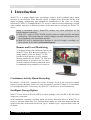

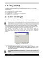
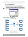
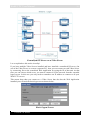
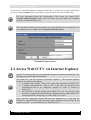
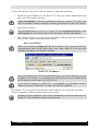
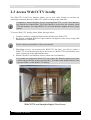

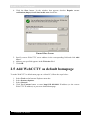
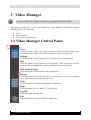
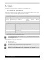
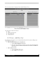
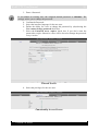
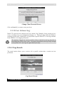
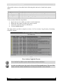
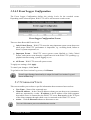
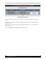

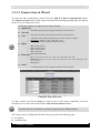
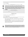
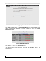

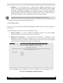
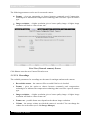
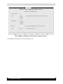
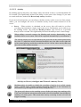
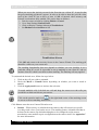
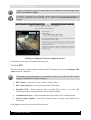
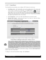
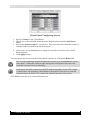
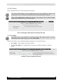
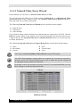
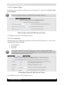
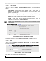
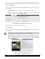
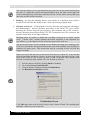
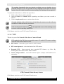

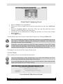
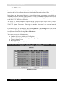
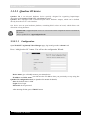
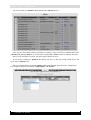
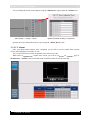

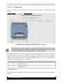
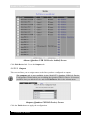
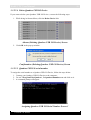

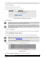
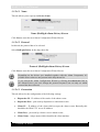
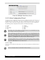

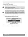
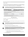
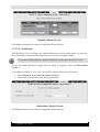
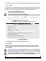
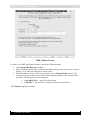
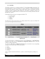
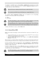
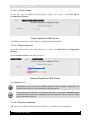
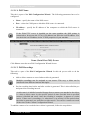
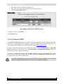
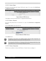
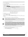
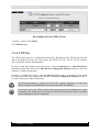
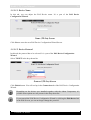
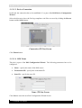
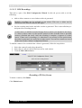
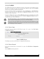
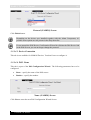

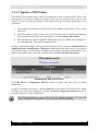


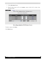
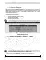
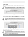
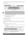
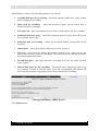
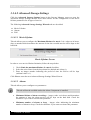
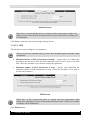
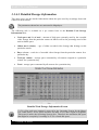
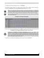

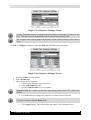
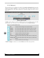
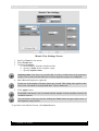
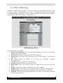
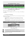

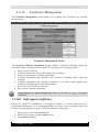
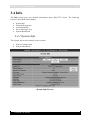
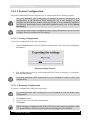

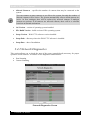
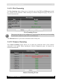
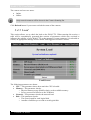
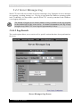
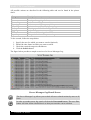
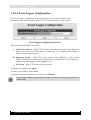
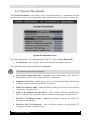

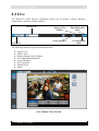
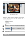
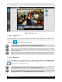
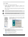
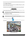
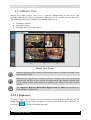
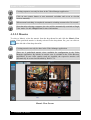
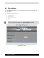
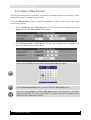
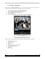
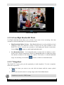

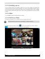
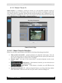
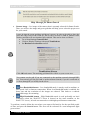
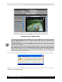
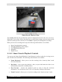

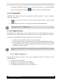
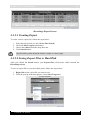
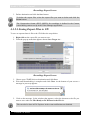
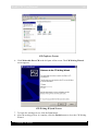


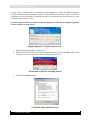
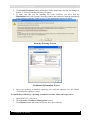
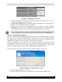
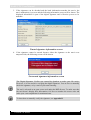
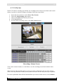
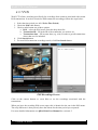
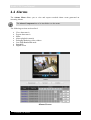
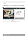
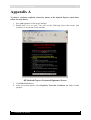

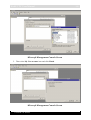
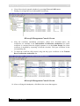
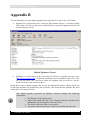
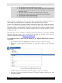
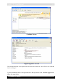
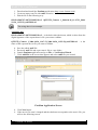
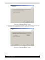


![[MANUAL] WebCCTV User Manual 4.4.0.0](http://vs1.manualzilla.com/store/data/005886634_1-9e25e0c8c7fa6f72c2b69bbb4cc67aa8-150x150.png)

![[MANUAL] WebCCTV Installation Manual 4.4.0.0](http://vs1.manualzilla.com/store/data/005935803_1-1275fe61ae4b5b7c0ce4f62506e594f6-150x150.png)

![[MANUAL] GuardNVR Installation Manual 4.4.0.0](http://vs1.manualzilla.com/store/data/005799040_1-22ffd5d438f0b0c95843f8ff9431bc2d-150x150.png)