1
Easidew Online
Dew-Point Hygrometer
User’s Manual
Ea
si
°Cd
p
°Fd
p
de
w
O
nl
in
e
H
yg
r
om
et
March 2014
er
Easidew Online
For Kahn Instruments' contact information please go to
www.Kahn.com
Easidew Online User’s Manual
Contents
Safety................................................................................................................................. iv
Electrical Safety............................................................................................................ iv
Pressure Safety............................................................................................................. iv
Toxic Materials.............................................................................................................. iv
Repair and Maintenance................................................................................................ iv
Calibration.................................................................................................................... iv
Safety Conformity......................................................................................................... iv
Abbreviations.......................................................................................................................v
Warnings.............................................................................................................................v
1INTRODUCTION.................................................................................................1
1.1Features............................................................................................................. 2
2INSTALLATION...................................................................................................3
2.1 Unpacking the Instrument.................................................................................... 3
2.1.1
Unpacking the Easidew Transmitter................................................................. 4
2.1.2
Unpacking the Monitor................................................................................... 4
2.1.3
Accessories Pack............................................................................................ 5
2.2 Easidew Online Components................................................................................ 5
2.3 Easidew Transmitter............................................................................................ 6
2.4Monitor............................................................................................................... 7
2.5 Monitor Panel Layout........................................................................................... 7
2.6 Function Keys...................................................................................................... 9
2.7 Mounting the Monitor........................................................................................ 10
2.8 Electrical Connections........................................................................................ 11
2.8.1
AC Power Supply Input................................................................................. 12
2.8.2
DC Power Supply Input (Optional)................................................................. 13
2.8.3
Preliminary System Test................................................................................ 14
2.9 Mounting the Sample Block and Transmitter........................................................ 14
2.9.1
Sample Block Gas Connections...................................................................... 14
2.9.2
Transmitter Mounting - Sample Block............................................................. 16
2.9.3
Transmitter Mounting - Direct Pipeline Connection.......................................... 17
2.10 Preparation of the Transmitter Cable................................................................... 18
2.11 Electrical Schematic........................................................................................... 19
2.11.1 Electrical Boundaries.................................................................................... 20
2.12 Transmitter Cable Connection............................................................................. 20
2.12.1 Transmitter Connections............................................................................... 20
2.12.2 Monitor Connection...................................................................................... 21
2.13 Signal Output Connections................................................................................. 22
3OPERATION.....................................................................................................24
3.1
3.2
3.2.1
3.3
3.3.1
3.3.2
3.3.3
3.3.4
3.4
3.4.1
3.4.2
General Operational Information ........................................................................ 24
Preparation For Operation.................................................................................. 25
First Time Operation..................................................................................... 25
System Alarms.................................................................................................. 26
Alarm Switching Logic (Default).................................................................... 26
Reversal of Alarm Switching Logic................................................................. 27
Alarm Level Set-Up...................................................................................... 29
Re-Transmitted Output Current Range Set-Up................................................ 30
Operating Temperature / ppmV Range ................................................................ 31
Temperature Range Default.......................................................................... 31
Span and Unit Settings ................................................................................ 32
Kahn Instruments
i
Easidew Online User’s Manual
3.4.3
Alarm Set-Point Limit Configuration............................................................... 33
3.4.4
Scale Units to ppmV Set-Up........................................................................... 34
3.4.5
Monitor Limits When Unit Scaled to ppmV ..................................................... 35
3.5 Digital Communication Parameters Set-Up........................................................... 36
3.6 Monitor – Reading the Displayed Value Using Modbus RTU Over RS232................. 38
4
GOOD MEASUREMENT PRACTICE......................................................................39
4.1 General Operational Guidelines .......................................................................... 40
4.2 Maintenance and Calibration ............................................................................. 41
4.2.1
Clean Monitor ............................................................................................. 41
4.3 Fault Conditions................................................................................................ 42
Figures
Figure
Figure
Figure
Figure
Figure
Figure
Figure
Figure
Figure
Figure
Figure
Figure
Figure
Figure
Figure
Figure
Figure
Figure
Figure
Figure
Figure
Figure
Figure
Figure
Figure
Figure
Figure
Figure
Figure
Figure
Figure
Figure
Figure
1
2
3
4
5
6
7
8
9
10
11
12
13
14
15
16
17
18
19
20
21
22
23
24
25
26
27
28
29
30
31
32
33
Easidew Online Monitor and Transmitter........................................................1
Unpacking Method.......................................................................................3
Transmitter Unpacking Method.....................................................................4
Monitor Unpacking Method...........................................................................4
Accessories Pack.........................................................................................5
Easidew Online Components........................................................................5
Easidew Transmitter....................................................................................6
Monitor Panel Layout...................................................................................7
Mounting the Monitor................................................................................10
AC Power Supply Connections....................................................................12
DC Power Supply Connections....................................................................13
Sample Block Gas Connections...................................................................15
Transmitter Mounting - Sensor Block...........................................................16
Transmitter Mounting - Pipe or Duct...........................................................17
Connector Terminal Block Removal.............................................................18
Wiring Connections....................................................................................19
2-Wire Connection Diagram........................................................................19
Maximum Load of Easidew - Including Cable Resistance...............................20
Connector Installation................................................................................20
Transmitter Connections............................................................................21
Monitor Rear Panel Connections.................................................................22
Typical Display..........................................................................................25
Change Alarm Switching Logic....................................................................28
Set-up Alarm Levels...................................................................................29
Configure Analog Output............................................................................30
Span and Unit Settings..............................................................................32
Set-up Alarm Set-Point Limits.....................................................................33
Set-up Monitor (to read ppmV)....................................................................35
Set-up Data Communications Parameters....................................................37
Installation Location..................................................................................40
Indication of Dead Space...........................................................................40
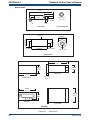
Dimensions ..............................................................................................46
RS232 Connections....................................................................................48
ii March 2014
Easidew Online User’s Manual
Tables
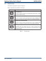
Table 1
Table 2
Table 3
Monitor Front Panel Controls and Indicators...................................................8
Function Keys...............................................................................................9
Summary of Electrical Connections.............................................................. 23
Appendices
Appendix A
Appendix B
Appendix C
Technical Specifications............................................................................... 43
RS232 Data Communications Port Connections (Optional)............................. 47
UL Certification........................................................................................... 49
Kahn Instruments
iii
Easidew Online User’s Manual
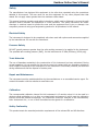
Safety
The manufacturer has designed this equipment to be safe when operated using the procedures
detailed in this manual. The user must not use this equipment for any other purpose than that
stated. Do not apply values greater than the maximum value stated.
This manual contains operating and safety instructions, which must be followed to ensure the safe
operation and to maintain the equipment in a safe condition. The safety instructions are either
warnings or cautions issued to protect the user and the equipment from injury or damage. Use
competent personnel using good engineering practice for all procedures in this manual.
Electrical Safety
The instrument is designed to be completely safe when used with options and accessories supplied
by the manufacturer for use with the instrument.
Pressure Safety
DO NOT permit pressures greater than the safe working pressure to be applied to the instrument.
The specified safe working pressure (SWP), for this instrument is 45 MPa (450 barg / 6500 psig).
Toxic Materials
The use of hazardous materials in the construction of this instrument has been minimized. During
normal operation it is not possible for the user to come into contact with any hazardous substance
which might be employed in the construction of the instrument. Care should, however, be exercised
during maintenance and the disposal of certain parts.
Repair and Maintenance
The instrument must be maintained either by the manufacturer or an accredited service agent. For
contact information visit the website at www.Kahn.com
Calibration
The recommended calibration interval for this instrument is 12 months unless it is to be used in a
mission-critical application or in a dirty or contaminated environment in which case the calibration
interval should be reduced accordingly. The instrument should be returned to the manufacturer,
Kahn Instruments Inc., or one of their accredited service agents for re-calibration.
Safety Conformity
This product meets the essential protection requirements of the relevant EU and US directives.
iv
March 2014
Easidew Online User’s Manual
Abbreviations
The following abbreviations are used in this manual:
AC alternating current
atm pressure unit (atmosphere)
barg pressure unit (=100 kP or 0.987 atm) gauge
bara bar absolute
°C degrees Celsius
°F degrees Fahrenheit
DC direct current
ft foot (feet)
ggram(s)
Hz Hertz
lbf-ft
pound force per foot
Nl/min
normal liters per minute
m
meter(s)
mA milliampere
max maximum
min minute(s)
mm millimeter(s)
MPa megapascal (Pascals x106)
m/sec
meters per second
Nm
Newton meter
ppmV parts per million (by volume)
RS232 serial data transmission standard
Rx receive
scfh
standard cubic feet per hour
scfs
standard cubic feet per second
SWP safe working pressure
sec second(s)
temp temperature
V
Volts
Ω
Ohms
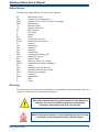
Warnings
The following general warnings listed below are applicable to this instrument. They are
repeated in the text in the appropriate locations.
Where this hazard warning symbol appears in the following
sections, it is used to indicate areas where potentially
hazardous operations need to be carried out.
Where this symbol appears in the following sections it is used
to indicate areas of potential risk of electric shock.
Kahn Instruments
v
Easidew Online User’s Manual
1
INTRODUCTION
INTRODUCTION
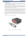
The Easidew Online dew-point hygrometer is an instrument designed for the continuous
online measurement of moisture content in non-corrosive gases, over an operational
range of -148 to +68ºFdp (-100 to +20ºCdp).
The system is comprised of a programmable monitor configured to accept a 4-20 mA
current loop signal from a capacitance-type dew-point measurement transmitter. The
range of the transmitter is set to cover the dew-point range -148 to +68ºFdp (-100 to
+20ºCdp) at operating pressures up to 5000 psig.
The monitor also has a re-transmission facility which buffers the transmitter output for
onward transmission to other systems. The transmitter input to the monitor is configured
as a 4-20 mA current loop signal and the re-transmitted output can be configured as
either a 4-20 mA or a 0-20 mA current loop signal (ranged as per the input).
Two alarm outputs (high and low) are provided for connection to external systems.
Alarm 1 provides a set of single pole make contacts and Alarm 2 provides a set of
changeover contacts. Both sets are potential free and Alarm 1 contacts (single pole
type) are rated at 250 V, 3 A and the Alarm 2 contacts (changeover) are rated at
250 V, 5 A.
Figure 1 shows the monitor and the transmitter.
Ea
si
°Cd
p
°Fd
p
de
w
O
nl
in
e
H
yg
r
om
et
Figure 1
er
Easidew Online Monitor and Transmitter
Kahn Instruments
1
INTRODUCTION
1.1
Easidew Online User’s Manual
Features
The Easidew Online Hygrometer is simple to use and install, and can be configured to
meet specific needs.
•
5/8”- 18 UNF process connections
•
Dew-point or ppmV moisture content
•
NEMA 4 (IP66) Sensor and NEMA 12 (IP65) Monitor (front panel only)
•
Measurement range -100 to +20°C (-148 to +68°Fdp)
•
Dual alarms
•
Accuracy ±2°Cdp
•
Clear and easy to read display
•
Calibration certificate (traceable to NIST)
2
March 2014
Easidew Online User’s Manual
2
INTRODUCTION
INSTALLATION
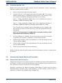
It is essential that the connection of electrical and gas supplies
to this instrument be undertaken by competent personnel.
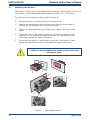
2.1
Unpacking the Instrument
The Easidew instrument and accessories are packed into a box and the method of
unpacking is shown as follows:
1
2
4
3
Figure 2
Unpacking Method
Open the box and unpack carefully as follows. Save all the packing materials for the
purpose of returning the instrument for re-calibration or any warranty claims.
1.
Remove the top packing (1)
2.
Remove the dew-point transmitter box (3)
3.
Remove the accessories pack (4)
4.
Remove the monitor box (2)
Kahn Instruments
3
Easidew Online User’s Manual
INSTALLATION
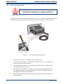
2.1.1
Unpacking the Easidew Transmitter
NOTE: For environmental and operating conditions refer to Appendix A.
Unpack the dew-point transmitter box as follows:
1
2
3
Figure 3
4
5
6
Transmitter Unpacking Method
1.
Remove the cap (1) from the packing tube (6). Remove the foam block
(2).
1.
Remove the transmitter from the tube, complete with the body cover (4)
and tip cover (5).
2.
Remove the body cover (4) and the tip cover (5) but leave the blue plastic
protective cover (3) in place until ready for installation.
NOTE: The transmitter sensing element is protected while in transit by a blue
cover containing a small desiccant capsule. The connection pins are protected
by a red plastic cap. None of these plastic items are required for the operation
of the transmitter.
2.1.2
Unpacking the Monitor
The monitor (2) is packed, together with its installation clamps (1) as shown below.
Figure 4
Monitor Unpacking Method
4
March 2014
Easidew Online User’s Manual
2.1.3
INSTALLATION
Accessories Pack
The accessories pack is shown below.
1
3
2
4
Figure 5
Accessories Pack
Remove the screwdriver (1), the two leads (2) and (3) and the sample block (4) from
the bag.
2.2
Easidew Online Components
On delivery please check that all the following standard components are present in the
packing box. Report any shortages to Kahn Instruments, immediately.
Figure 6
1.
Monitor clamps (2 off)
2.
Easidew Monitor
3.
Transmitter cable assembly
4.
Power cable
5.
Screwdriver
6.
User’s Manual
7.
Calibration certificate
8.
Sample block
9.
Easidew transmitter
Easidew Online Components
Kahn Instruments
5
Easidew Online User’s Manual
INSTALLATION
2.3
Easidew Transmitter
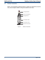
NOTE: The transmitter’s sensing element is shown for illustration purposes
only. Please keep the HDPE or SS guard installed at all times.
Sensing Element
Process Connection
Hexagonal Nut
HeEn
MIC
trum
Ins
09
SF72
R an ge:
0
- 100 / +2
06
B
y
Wa
st er
es
48 Lan ca
id g
m br
Ely, Ca
6
CB
g
in
dK
Un ite
Figure 7
Transmitter Label
Transmitter Cover
Electrical Connector
Easidew Transmitter
6
March 2014
Easidew Online User’s Manual
2.4
INSTALLATION
Monitor
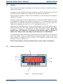
The controls and indicators associated with the Easidew Online are located on the front
panel of the monitor.
Connections to the Easidew dew-point transmitter, the RS232 communications port and
the external power supply are all made to the rear panel of the monitor.
Figure 8 shows the layout of these controls and Tables 1 and 2 describe their respective
operational functions.
Dew-point temperature units are displayed by one of the two LED’s located to the left
of the display. On delivery, the monitor is set-up as °F or °C depending on the order
specification. If required, the units can be changed from °C to °F or vice-versa. The
method of configuring the unit for °C or °F is described in Section 3.4.
Optionally, the instrument can be set-up to read dew point in parts per million (ppmV),
range 0 to 3000 ppmV. This option requires the transmitter to be set-up for ppmV either
at the time of ordering or subsequently via Kahn application software. NOTE: No
specific ppmV LED indicator is provided on the monitor; ppmV is selected if
neither the °Cdp nor the °Fdp temperature indicators are illuminated.
Two temperature alarm indications are provided by two LEDs located on the right hand
side of the display. These are marked AL1 (low) and AL2 (high). Access to the alarm
relay contacts is provided on the rear panel. The connection for these alarm relay
contacts is shown in Section 2.13.
NOTE: Every display is factory installed with 2 alarm relays as standard.
2.5
Monitor Panel Layout
Easidew Online
Hygrometer
6
Figure 8
Monitor Panel Layout
Kahn Instruments
7
Easidew Online User’s Manual
March 2014
INSTALLATION
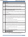
Item
Description
°Fdp
1
When illuminated, this LED indicates that the displayed dew-point reading is in degrees
Fahrenheit.
Note: If neither the °Fdp or °Cdp LED is lit, ppmV is selected.
°Cdp
2
When illuminated, this LED indicates that the displayed dew-point reading is in degrees
Celsius.
Note: if neither the °Cdp nor °Fdp LED is lit, ppmV is selected.
Main dew-point temperature display
3
Flashes to alternately indicate ErrL (error low) and temperature reading for low dewpoint
under-range (lower than -148°Fdp (-100°Cdp) or 199.9°Fdp (-129.9°Cdp) for an open
loop condition).
Flashes to alternately indicate ErrH (error high) and temperature reading for high
temperature over-range.
AL1
4
When illuminated, this LED indicates that the dew-point temperature programmed
for Alarm 1 has exceeded the programmed threshold. Under these conditions the
alarm relay contacts associated with this alarm (normally open) will change state
(close) and will remain closed until the dew-point temperature moves back within
the programmed operational limit.
Alarm 1 is usually allocated to the Low alarm setting.
These relay contacts are rated at 250 V, 3 A and are connected as shown in Section 2.13.
Section 3.3.3 describes the setting up of AL1 trip points.
AL2
5
When illuminated this LED indicates that the dew-point temperature programmed for
Alarm 2 has exceeded the programmed threshold. Under these conditions the alarm
relay changeover contacts associated with this alarm will change state and will remain in
this state until the temperature moves back to within the programmed operational limit.
Alarm 2 is usually allocated to the High alarm setting.
These changeover relay contacts are rated at 250 V, 5 A and are connected as shown
in Section 2.13.
6
Section 3.3.3 details the setting up of AL2 trip points.
The four function keys are used for setting up the
monitor.
SET
P
Table 2 describes the operation of the keys.
Table 1
Monitor Front Panel Controls and Indicators
8
March 2014
Easidew Online User’s Manual
2.6
INSTALLATION
Function Keys
The function key panel is shown in Figure 8.
Table 2 describes the operation of the keys.
Item
P
Description
P (Program) key
This key is used to access the programming menus and to select
sub-menus within the list.
Left arrow (decrement) key
This key is used to access sub-menus and, within individual submenus, to decrease the numeric value of the selected parameter.
Right arrow (increment) key
This key is used to access sub-menus and, within individual submenus, to increase the numeric value of the selected parameter.
SET key
SET
Depending upon the context, this key is used to access the set
value of the selected process field and as an Accept key for new
parameter values.
Table 2
Function Keys
Kahn Instruments
9
Easidew Online User’s Manual
INSTALLATION
2.7
Mounting the Monitor
The monitor is designed for panel mounting and requires a panel cut-out of 1.8 x 3.6”
(46 x 92mm). The recommended panel thickness is 0.08 to 0.2” (2 to 5mm).
To mount the unit, proceed as follows (refer to Figure 9):
1.
Pass the monitor (1) through the front of the panel (2).
2.
Support the monitor and insert the hook on the topside of the clamp (3)
into the slot (4) located on top of the monitor case
3.
Tighten the adjustment screw (5) finger tight, against the back of the
panel.
4.
Insert the hook on the second clamp (6) into the slot located on the
underside of the instrument casing and tighten the adjustment screw,
finger tight, against the back of the panel.
5.
Insure that the monitor is sitting flush to the front of the panel (2) and
tighten the adjustment screws evenly against the back of the panel.
Caution: Do not overtighten the screws as this could cause
the case to crack.
2
3
1
5
4
6
Figure 9
Mounting the Monitor
10
March 2014
Easidew Online User’s Manual
2.8
INSTALLATION
Electrical Connections
Electrical connections to the Easidew Online system are as follows:
•
AC power supply, 100 to 240 V AC (-15%, +10%), 50/60 Hz, 6 VA. A low
voltage (24 V DC) option is also available.
•
Transmitter current loop input, 4-20 mA (24 V DC loop power provided
by monitor).
•
Alarm 1 (Low), potential free contacts, single pole make. Contacts rated
at 250 V, 5 A.
•
Alarm 2 (High), potential free contacts, single pole changeover. Contacts
rated at 250 V, 5 A.
•
Re-transmitted input signal from the dew point transmitter 4-20 mA or
0-20 mA.
Kahn Instruments
11
Easidew Online User’s Manual
INSTALLATION
2.8.1
AC Power Supply Input
It is essential that the connection of electrical supplies to this
instrument be undertaken by competent personnel.
Connect the AC power supply to the monitor as shown in Figure 10. Refer also to Table
3 which gives a summary of all the connections to the rear panel of the monitor.
1
2
3
14 15
4
16
5
6
17
18
7
19
8
9
10 11
22 23
20 21
4
2
3
Monitor
viewed from underneath
Figure 10
AC Power Supply Connections
1.
Insure that no power is connected to the power lead.
2.
Connect the blue (white - US standard) (neutral) lead (2) to terminal 23
on the rear panel of the monitor.
3.
Connect the brown (black - US standard) (live) lead (3) to terminal 24 on
the rear panel of the monitor.
4.
Strip back the insulation on the free end of the power cable and wire to
an appropriate power supply plug (brown lead to live supply terminal,
blue lead to neutral supply terminal).
5.
Check that the wiring has been completed correctly before connecting to
a power supply.
12
March 2014
Easidew Online User’s Manual
2.8.2
INSTALLATION
DC Power Supply Input (Optional)
Connect the DC power supply to the monitor as shown in Figure 11. Refer also to Table
3 which gives a summary of all the connections to the rear panel of the monitor.
1
2
3
14 15
5
6
7
4
17
18
19
16
10 11
8 9
22 23
20 21
4
2
3
-
+
Monitor
viewed from underneath
Figure 11
DC Power Supply Connections
1.
Insure that no power is connected to the power lead.
2.
Connect the blue (white - US standard) lead (2) to terminal 23 on the rear
panel of the monitor.
3.
Connect the brown (black - US standard) lead (3) to terminal 24 on the
rear panel of the monitor.
4.
Strip back the insulation on the free end of the power cable and wire
to an appropriate power supply plug (brown lead to positive (+) supply
terminal, blue lead to negative (-) supply terminal).
5.
Check that the wiring has been completed correctly before connecting to
a 24 V power supply.
Kahn Instruments
13
INSTALLATION
2.8.3
Easidew Online User’s Manual
Preliminary System Test
Before wiring the external signal outputs and the transmitter (current loop open),
perform a system check as follows:
1.
Switch off and disconnect the power supply.
2.
Connect to an AC or DC supply and switch the supply ON. The monitor
display should come on. Depending on the version of the monitor, there
are 2 types of sequential messages appearing on the display.
Type 1: - Digits sequentially tested, each in turn displaying the figure 8
followed by rUO2 then oAor and Sbr
Type 2: - Digits sequentially tested, each in turn displaying the figure 8
followed by ruOO then oror and alternately flashing ErrL and -129.9
The ºCdp LED will, by default, also be illuminated and it is possible, that
even though no alarms are currently set-up, one of the alarm LED’s may be
illuminated.
NOTE: If the instrument is configured to read ppmV neither of the
temperature LED indicators will be lit.
3.
If a loop calibrator is available, set it to Ext loop and connect to terminal
4 (positive) and terminal 3 (negative) of the process indicator.
4.
Set the output current of the loop calibrator to 4 mA, the display should
now be reading -100.0.
5.
Set the output current of the loop calibrator to 20 mA, the display should
now be reading 020.0.
6.
Switch off and disconnect the loop calibrator.
Before wiring the external signal outputs and the transmitter, perform a system check
as follows:
2.9
Mounting the Sample Block and Transmitter
2.9.1
Sample Block Gas Connections
Sample gas connections are made to the Gas In and Gas Out ports on the sample block
see Figure 12. Either port on the sample block may be used as the Gas Input port (i.e.
for connection purposes the ports are interchangeable).
Normally, connections are made via stainless steel tubing, in which case the sensor
block/transmitter assembly will be self supporting. If Teflon tubing is used it may be
necessary to support the assembly with a support clip.
March 2014
14
Easidew Online User’s Manual
INSTALLATION
1
2
3
6
4
5
5
5
4
4
3
3
2
1
2
1
Figure 12
Sample Block Gas Connections
Both the Input and Output gas connections are ⅛” NPT. It is recommended that both
the Gas Input and Output connections are made made via ⅛” NPT to 6mm or ⅛” NPT
to ¼” stainless steel tube adaptors (2 to 5 - Figure 12). The method of connection to
the sensor block (6) is as follows:
NOTE: The following description relates to 6mm tube fixings. The sample
block ports are both ⅛” NPT female process connections. Tube adaptors are
not supplied with the equipment but can be obtained by contacting your local
distributor or Kahn Instruments (see www.Kahn.com for details).
1.
Cut a suitable length of ¼” U.S. 6mm (6mm) stainless steel tubing (1) to
the correct length and, if necessary, bend to shape to suit the location of
the sensor block assembly. NOTE: To facilitate ease of connection to
the port, at least 3” (75mm) of the tubing coming out of the Gas
In port must be straight.
2.
Clean off any burrs or metal shavings adhering to the tubing.
3.
Screw the ¼” U.S. (⅛” NPT) NPT Swagelok adaptor (5) into the ¼” U.S. (⅛” NPT) NPT inlet port in the sensor block (6) and tighten to a torque
setting of 25 lbf-ft (35 Nm).
4.
Pass the stainless steel tubing (1) through the locking nut (2). NOTE:
Threads towards the gas port.
5.
Fit the back ferrule (3) over the stainless steel tubing (1) with the bevelled
end facing the back of the front ferrule (4).
6.
Place the front ferrule (4) over the stainless steel tubing (1), bevelled end
towards the adaptor (5).
7.
Push the stainless steel tubing (1) as far as it will go into the adaptor (5)
and tighten up the locking nut (2) finger tight.
8.
Hold the adaptor (5) flats with a wrench and tighten up the locking
nut (2) to a torque setting of 25 lbf-ft (35 Nm) (1¼ turns). This action
compresses the front ferrule (4) and back ferrule (3) onto the tubing to
form a gas tight seal.
9.
Connect up the other gas port as described in steps 1 to 8 above.
Kahn Instruments
15
Easidew Online User’s Manual
INSTALLATION
2.9.2
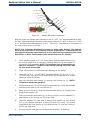
Transmitter Mounting - Sample Block
The following procedure must be carried out by a qualified
installation technician.
To mount the transmitter into the sensor block (preferred method), proceed as follows
(refer to Figure 13):
1.
Remove the blue protective cover (2) and its desiccant capsule (2a), from
the tip of the transmitter.
2.
Place the bonded seal (4) over the threaded part of the transmitter body.
WARNING: Under no circumstances should the filter guard be
handled with the fingers.
3.
Screw the transmitter (1) into the sample block (3) and tighten to a
minimum torque setting of 22 lbf-ft (30 Nm). NOTE: Use the flats of
the hexagonal nut and not the sensor body.
2
2a
1
3
4
Figure 13
Transmitter Mounting - Sensor Block
5
16
March 2014
Easidew Online User’s Manual
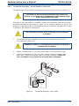
2.9.3
INSTALLATION
Transmitter Mounting - Direct Pipeline Connection
The transmitter may be directly mounted into a pipe or duct as shown in Figure 14.
CAUTION: Do not mount the transmitter too close to the
bottom of a bend where any condensate in the pipeline might
collect and saturate the probe.
The pipe or duct will require a thread to match the transmitter process connection.
Installation dimensions are shown in Figure 14. For circular pipework, to ensure the
integrity of a gas tight seal, a mounting flange will be required on the pipework in order
to provide a flat surface to seal against.
The following procedure must be carried out by competent
personnel.
1.
Insure that the blue protective cover has been removed from the tip of
the transmitter (Figure 13).
WARNING: Under no circumstances should the filter guard be
handled with the fingers.
2.
Attach a bonded seal (2) over the threaded part of the transmitter body.
3.
Screw the transmitter (3) into the pipe. Tighten enough to obtain a gas
tight seal. (Torque will depend upon the pipeline material.) NOTE: Do
not overtighten or the thread on the pipe may be stripped.
1
2
3
1
48mm
Figure 14
2
3
Transmitter Mounting - Pipe or Duct
Kahn Instruments
17
Easidew Online User’s Manual
INSTALLATION
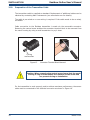
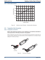
2.10
Preparation of the Transmitter Cable
The transmitter cable is supplied as standard. Replacement of additional cables can be
obtained by contacting Kahn Instruments (see www.kahn.com for details).
The cable is pre-wired so no user wiring is required. If the cable needs to be re-wired,
see below.
Cable connection to the Easidew transmitter is made via the removable connector.
Removing the central screw enables the connector terminal block to be removed from
the outer housing by using a small screwdriver to pry it clear.
O-ring
and washer
Figure 15
Connector Terminal Block Removal
Caution: When removing the central screw insure that the small
sealing O-ring and the washer are retained on the screw and
are present during re-installation.
For the transmitter to work properly, and to achieve maximum performance, the sensor
cable must be connected to the electrical connector as shown in Figure 16.
18
March 2014
Easidew Online User’s Manual
INSTALLATION
NOTE: The drawing below shows the identity of the connector terminals and
wiring connections of the cable manufactured by Kahn Instruments.
GN
GREEN - 4-20 mA
RED + POWER
BLUE - SCREEN
RD
BL
3
BLUE
BRAID
SCREEN
GREEN
YELLOW
RED
+POWER
1
BRAID
GREEN
SIGNAL (SOURCE)
SHORT
AS POSSIBLE
BLUE
RED
GND
2 4
GREEN - 4-20 mA
(SOURCE)
BLUE - SCREEN
RED + POWER
VIEW ON REAR
OF CONNECTOR
SCALE 2:1
Figure 16
Wiring Connections
Always connect the 4-20 mA return signal to a suitable load
(see Figure 16) before the power is applied. Without this
connection, the transmitter may be damaged if allowed to
operate for prolonged periods.
2.11
Electrical Schematic
NOTE: The screen/shield should be connected for maximum performance
and to avoid interference.
3
1
+
Screen/
Shield
Figure 17
Max Load
250R @ 12V
500R @ 24V
Supply
12V Min
28V Max
2-Wire Connection Diagram
Kahn Instruments
19
Easidew Online User’s Manual
INSTALLATION
2.11.1 Electrical Boundaries
Resistance (ohms)
600
500
400
300
200
100
12
14
16
18
20
22
24
26
28
Supply Voltage
Figure 18
2.12
Maximum Load of Easidew - Including Cable Resistance
Transmitter Cable Connection
2.12.1 Transmitter Connections
NOTE: The following procedure can be followed for transmitters mounted in
the sample block or directly mounted in the pipeline.
When installing the connector, and to insure that full ingress protection is achieved, the
securing screw (with the O-ring and washer) must be tightened to a minimum torque
setting of 2.5 ft-lbs (3.4 Nm).
O-ring
and washer
Figure 19
Connector Installation
20
March 2014
Easidew Online User’s Manual
INSTALLATION
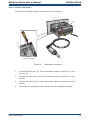
2.12.2 Monitor Connection
Connect the transmitter cable to the monitor as shown below:
2
3
4
1
2
3
14 15
4
3
5
6
7
4
17
18
19
16
10 11
8 9
22 23
20 21
2
Monitor
viewed from above
Figure 20
Transmitter Connections
1.
Connect the blue wire (2) of the transmitter cable to terminal 1 on the
monitor (1).
2.
Connect the green wire (3) of the transmitter cable to terminal 3 on the
monitor.
3.
Connect the red wire (4) of the transmitter cable to terminal 4 on the
monitor.
4.
Check that the transmitter cable wiring has been completed correctly.
Kahn Instruments
21
Easidew Online User’s Manual
INSTALLATION
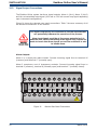
2.13
Signal Output Connections
The Easidew Online system has three signal outputs, Alarm 1 (ALr1), Alarm 2 (ALr2)
and the re-transmitted input signal (4-20 mA or 0-20 mA current loop signal depending
upon instrument configuration).
Figure 21 shows the relevant rear panel connections. Table 3 shows a summary of all
the electrical connections to the monitor.
The signal outputs will be connected to external systems that
can potentially influence the operation of the process.
Alarm level signals could be at line power potential so it is
essential that, before connecting these signal lines, checks are
made to insure that these inputs are not live and that it is safe
to handle them.
Alarm Outputs
Alarm 1 is a single pole make contact. Connect incoming signal lines to terminal 16
(common) and terminal 17 (normally open).
Alarm 2 comprises a set of changeover contacts. Connect incoming signal lines to
terminal 9 (common), terminal 8 (normally open) and terminal 7 (normally closed).
Figure 21
Monitor Rear Panel Connections
22
March 2014
Easidew Online User’s Manual
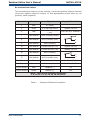
INSTALLATION
Re-transmission Output
The re-transmission output is current sourcing. Connect the positive output to terminal
14 and the negative output to terminal 13. Use appropriately colored wires eg, red
(positive), black (negative).
Terminal
Wire Color
Signal
Supply Information
1
Blue
0 V (GND)
3
Green
4-20 mA loop current
Default 4-20 mA
4
Red
Transmitter loop supply
(+ve)
+24 V DC w.r.t. terminal 1
7
User defined
ALR2 (normally closed)
8
8
User defined
ALR2 (normally open)
7
9
User defined
ALR2 (common)
9
13
User defined
Current loop out (-ve)
Default 4-20 mA
14
User defined
Current loop out (+ve)
Default 4-20 mA
16
User defined
ALR1 (common)
17
User defined
ALR2 (normally open)
23 (AC Version)
Blue
Power in (neutral)
100 – 240 V, 50/60 Hz
24 (AC Version)
Brown
Power in (live)
100 – 240 V, 50/60 Hz
23 (DC Version)
Blue
Negative (-)
0V
24 (DC Version)
Brown
Positive (+)
24 V
17
16
NOTE: There are no terminals in positions
5, 6, 10, 11, 12, 15, 18, 19, 20, 21 and 22
Table 3
Summary of Electrical Connections
Kahn Instruments
23
OPERATION
3
Easidew Online User’s Manual
OPERATION
As supplied, the instrument is ready for operation and has been set-up with a set of
default parameters. This section describes both the general operation of the instrument
and the method of setting it up and changing the default parameters should this become
necessary.
The default parameters are as follows:
•
Span -148 to +68°Fdp (-100 to +20°Cdp) or 0 to 3000 ppmV
•
Temperature units °Fdp or °Cdp.
•
Current loop input, 4-20 mA (13.5°F/mA or 7.5°C/mA)
•
Re-transmission current loop output, 4-20 mA (13.5°F/mA or 7.5°C/mA)
•
Alarm 1 set-point -4°Fdp (-20°Cdp)
•
Alarm 2 set-point -40°Fdp (-40°Cdp)
•
Data communications, Unit address 1, Baud rate 9600, Parity None, Stop
bits 1
For the supplied dew-point transmitter, the span and current loop input setting should
not be changed. The span will require changing if the instrument is to be ranged in
°F, if a different transmitter is employed, if the user chooses to re-range the Easidew
transmitter or if ppmV is selected.
The instrument must also have been installed as detailed in Section 2 and connected to
a sample gas supply that is representative of the process being monitored.
3.1
General Operational Information
Operation of the Easidew Online is completely automatic and once set-up requires little
or no operator intervention.
The dew-point transmitter is designed to operate in a flowing gas stream of between 2
and 10 scfh (1 and 5 Nl/min) when mounted in a sample block, at operating pressures
up to a maximum of 5000 psig. Direct pipeline mounting requires 0 to 33fps (1 to 10m/
sec) at pressures dependant on the type of material used (customer defined).
The sample gas is taken into the sample block via the Gas In port and, in flowing
through the sample block, comes into contact with the dew-point transmitter which,
in turn, produces a current loop output signal proportional to the measured dew-point
temperature. This output signal is converted to a real time analog dew-point temperature
reading by the monitor.
If data logging is required, the monitor will need to be connected to a suitable host and
temperature readings extracted via the RS232 interface.
The gas flow through the sample block must be controlled outside the instrument,
typically by means of a needle valve located in the sample gas input line.
24
March 2014
Easidew Online User’s Manual
3.2
Preparation For Operation
3.2.1
First Time Operation
OPERATION
To commence operation, proceed as follows:
1.
Check that electrical power supply and the relevant analog and alarm
outputs are connected to external systems as required and as described
in Sections 2.8 and 2.13.
2.
Check that the gas sample flow rate through the sample block, or the
pipeline in which the transmitter is located, is within the operational
limits. (Adjust any external flow control valves, located in the gas sample
input line to the instrument to achieve required flow rate.)
3.
Switch on the power supply to the instrument. The instrument display
will now come on, typically showing the default parameters and units as
detailed in Figure 22.
The instrument is now operational and after a few seconds, in which all the segments
of the display are tested, the monitor will display the measured dew-point temperature
as a steady reading within the range -148 to +68°Fdp (-100 to +20°Cdp) or 0 to 3000
ppmV depending upon how the instrument has been set-up.
In the absence of any error indications the instrument will now be operational using the
default parameters.
Easidew Online
Figure 22
Hygrometer
Typical Display
If the display is flashing, a fault condition exists. The following operational error
conditions may be encountered:
ErrL - If the display is alternately flashing (e.g.) ErrL and -103.3, this
indicates that the measured dew point is outside the lower operational limit
(-148°Fdp/-100°Cdp).
If the display is alternately flashing ErrL and -129.9 (-199.9 if set-up to read
temperature in °F), this could be an indication that the input current loop to
the monitor is open or that there may be a transmitter fault. Check that the
transmitter is wired correctly as detailed in Sections 2.10 and 2.12.
ErrH - If the display is alternately flashing (e.g.) ErrH and 021.4, this
indicates that the measured dew point is outside the upper operational
limit (+68°Fdp/+20°Cdp).
Kahn Instruments
25
Easidew Online User’s Manual
OPERATION
3.3
System Alarms
3.3.1
Alarm Switching Logic (Default)
The Easidew Online system has two alarm outputs. As supplied, the default alarm setpoints and the alarm switching logic are as follows (the default temperature units are
degrees Celsius):
Low Alarm - Alarm 1 (AL1) set to -20°Cdp
High Alarm - Alarm 2 (AL2) set to -40°Cdp
Alarm 1 (Low Alarm) is set-up to switch ON when the temperature reading is lower
(gas drier) than the alarm set-point value. For the default set-points therefore, the
default switching logic for these alarms is as follows:
Alarm 1 Temp < -20 Alarm 1 = ON
Temp > -20 Alarm 1 = OFF
Alarm 2 (High Alarm) is set to switch ON when the temperature reading is higher (gas
wetter) than its set-point value. For the default set-points therefore, the operation of
this alarm would be as follows:
Alarm 2 Temp < -40 Alarm 2 = OFF
Temp > -40 Alarm 2 = ON
Depending upon the application, if required, it is possible to reverse the switching logic
for either or both of the alarm channel outputs to provide the following alarm output
configurations:
Alarm 1 Temp < -20 Alarm 1 = OFF
Temp > -20 Alarm 1 = ON
Alarm 2 Temp < -40 Alarm 2 = ON
Temp > -40 Alarm 2 = OFF
Section 3.3.2 describes the method for reversing the default switching logic and Section
3.3.3 describes the method for setting up individual alarm set-points.
26
March 2014
Easidew Online User’s Manual
3.3.2
OPERATION
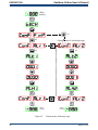
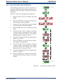
Reversal of Alarm Switching Logic
As described in Section 3.3.1, the switching logic for the alarm channels may, if required,
be individually reversed. Starting at the default state, the method of reversing the
switching logic for both alarms is as follows:
Figure 23 shows the operational key sequence.
For Alarm 1:
1.
Press the P key once and the display will read tECH.
2.
Press the SET key and the display will flash between ConF and PinP.
3.
Press the key twice and the display will flash between ConF and Alr1.
4.
Press the SET key twice to display Alt1.
5.
Press the key once to display a flashing 4 digit number. For the Alarm
1 default setting this will be 0001.
6.
Press the key once to change the display to 0000.
7.
Press the SET key to accept the new value. The default setting for Alarm
1 is now reversed.
8.
Either press the P key twice to return to the main display or press the P
key once followed by the key to move to the Alr2 setting sequence
from step 4 above.
To reverse the switching logic for Alarm 2 ONLY, proceed as follows:
1.
Press the P key once and the display will read tECH.
2.
Press the SET key and the display will flash between ConF and PinP.
3.
Press the key three times and the display will flash between ConF and
Alr2.
4.
Press the SET key twice to display Alt2.
5.
Press the key once to display a flashing 4 digit number. For the Alarm
2 default setting this will be 0000.
6.
Press the key once to change the display to 0001.
7.
Press the SET key to store the new value.
8.
Press the P key twice to return to the main display. The default setting for
Alarm 2 is now reversed.
Kahn Instruments
27
Easidew Online User’s Manual
OPERATION
Main
Display
P
SET
x3
x2
SET
(Change Alarm 2 Switching Logic)
SET
x2
SET
SET
P
P
P
P
Main
Display
Figure 23
x2
Main
Display
Change Alarm Switching Logic
28
March 2014
Easidew Online User’s Manual
3.3.3
OPERATION
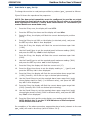
Alarm Level Set-Up
Main display
The alarm set-point levels are set-up
from the program menu as follows
(to exit to the main display without
saving any new settings press the P
key):
SET
Set x2 for Alarm 2 only
Figure 24 shows the operational key
sequence.
SET
Current
Value
To set-up both alarm set-points:
1.
2.
3.
4.
Press the SET key once, ALr1
will be displayed. (To set Alarm
2 only, press the SET key twice
and follow the Alarm 2 branch
instead).
Press the key to display the
flashing current Alarm 1 setpoint (-20°C in this example).
Use the and keys to set the
required value (-25.5°C in this
example).
Press the SET key once to store
the new (or existing) value for
Alarm 1 and to enter the setup menu for Alarm 2, ALr2. (To
exit to the main display without
changing Alarm 2 set-point
levels, press the P key.)
5.
Press the key to display the
flashing current Alarm 2 setpoint (-40°C in this example).
6.
Use the and keys to set
the required value (-50°C in
this example).
7.
Press the SET key once to store
the new value for Alarm 2. The
display then returns to the main
dew-point temperature display.
P
P to exit
without
setting
New
Value
P
SET
SET
P to exit
without
setting
P
P to exit if setting
Alarm 1 only
Current
Value
New
Value
SET
Main Display
Figure 24
Set-up Alarm Levels
Kahn Instruments
29
Easidew Online User’s Manual
OPERATION
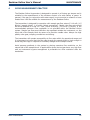
3.3.4
Re-Transmitted Output Current Range Set-Up
The Easidew Online is provided with an
analog current loop output module which
buffers and re-transmits the current loop
input signal from the dew-point transmitter.
P
By default, the re-transmission output is set
as a 4-20 mA current loop (to exactly follow
the input signal, i.e. 4 mA in, 4 mA out).
SET
For certain system processes, a 0-20 mA
current loop output may be required. The
set-up method is as follows:
Figure 25
sequence.
shows
the
operational
key
Change output from 4-20 mA to 0-20
mA
1.
Press the P key once, the display will
read tECH.
2.
Press the SET key and the display will
flash between ConF and PinP.
3.
Press the key and the display will
flash between out1 and ConF.
4.
Press the SET key to display oAt1.
5.
Press the key once to display a
flashing 4 digit number. For the default
setting (4-20 mA) this will be 0001.
6.
Press the key once to change the
display to 0000. This selects the retransmission output to be 0-20 mA.
7.
Press the SET key to accept the new
value. The output current loop is now
0-20 mA. The display will flash between
out1 and ConF.
8.
Press the P key once to return to the
main dew-point temperature display,
SET
Default setting
0001=4 to 20mA
New setting
0000=0 to20mA
SET
P
Main
Display
Figure 25
Configure Analog Output
Note: The transmitter current loop output signal is now scaled at 6 mA per °C
input, while the transmitter input remains scaled at 7.5°C per mA.
30
March 2014
Easidew Online User’s Manual
3.4
Operating Temperature / ppmV Range
3.4.1
Temperature Range Default
OPERATION
The default temperature unit for the Easidew Online instrument is in degrees Celsius.
This is indicated by the °Cdp LED indicator. The default settings associated with this
temperature scale are as follows:
•
Span -100 to +20°Cdp
•
Lower and upper span limits -100 and +20 (display flashes outside this
range)
•
Minimum alarm set-point -100°Cdp
•
Maximum alarm set-point +20°Cdp
To range the instrument for °F, all the above parameters need
to be changed to their Fahrenheit equivalent values (-148 and
+68°F). It is not sufficient just to change the °F/°C units.
To change the range to Fahrenheit follow the procedures in Sections 3.4.2 and 3.4.3.
Kahn Instruments
31
OPERATION
3.4.2
Easidew Online User’s Manual
Span and Unit Settings
To change the span and unit settings,
proceed as follows. Figure 26 shows the
operational key sequence.
1.
Press the P key once, the display will
read tECH.
2.
Press the SET key six times and the
display will read tPoL.
3.
Press the key and the display will
flash with the current minimum span
limit (-100.0).
4.
Use the and keys to set the
required equivalent Fahrenheit value
(-148.0) and press the SET key.
tPoH is then displayed.
5.
Press the key, the display will flash
the current maximum span limit
(020.0).
6.
Use the and keys to set the
required equivalent Fahrenheit value
(068.0) and press the SET key twice.
unit is then displayed.
7.
Press the key, the display will flash
the current unit (°C).
8.
Use the and keys to set the
required scale units (°F in this
example) and press the SET key.
LoL is then displayed.
9.
Press the key and the display will
flash with the current alarm lower
range limit (-100.0).
10. Use the and keys to set the
required equivalent Fahrenheit value
(-148) and press the SET key. uPL is
then displayed.
11. Press the key, the display will flash
the current alarm upper range limit
(020.0).
Figure 26
Span and Unit Settings
12. Use the and keys to set the required equivalent Fahrenheit value
(068.0) and press the SET key. PUoF is then displayed.
13. Press the P key twice to return to the main menu.
The maximum and minimum alarm level limits should now be changed to suit the new
(Fahrenheit) unit values (refer to Section 3.4.3).
32
March 2014
Easidew Online User’s Manual
3.4.3
OPERATION
Alarm Set-Point Limit Configuration
Main display
The following procedure is used to set limits to
which the alarm levels can be set (usually after reconfiguring the instrument’s range for Fahrenheit
readings).
P
Figure 27 shows the operational key sequence.
2.
Press the SET key once and the display will
flash between ConF and PinP.
3.
Press the key four times and the display
will flash between ConF and GEnn.
4.
Press the SET key once, the display will read
SU-L.
5.
Press the key once to display a flashing
4 digit number representing the current
minimum alarm level setting. (The default
setting for the °C range is -100.0).
6.
Use the and keys to set the required new
value (e.g. -148.0).
7.
Press the SET key to accept the new value.
The display will read SU-u.
8.
Press the key once to display a flashing
4 digit number representing the current
maximum alarm level setting. (The default
setting for the °C range is 020.0)
9.
Use the and keys to set the required new
value (e.g. 068.0).
x4
SET
Set alarm setpoint lower limit
Press the P key once, the display will read
tECH.
SET
Set span alarm setpoint upper limit
1.
SET
10. Press the SET key to accept the new value,
followed by the P key to return to the main
display.
SET
P
Main display
Figure 27
Set-up Alarm Set-Point Limits
Kahn Instruments
33
OPERATION
3.4.4
Easidew Online User’s Manual
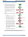
Scale Units to ppmV Set-Up
To change the monitor to read parts per million by volume (ppmV) proceed as follows:
Figure 28 shows the operational key sequence.
NOTE: The dew-point transmitter must be configured to provide an output
proportional to ppmV which can be set up at the time of order or by using the
Kahn application software. Contact Kahn Instruments for information (for
contact details see www.Kahn.com).
1.
Press the P key once, the display will read tECH.
2.
Press the SET key four times and the display will read dPnt.
3.
Press the key, the display will flash the current decimal point position
(0001).
4.
Press the key to set 0000 on the display (no decimal point), and press
the SET key twice. tPoL is then displayed.
5.
Press the key, the display will flash the current minimum span limit
(-1000)
6.
Use the and keys to set the required ppmV minimum reading (0000)
and press the SET key. tPoH is then displayed.
7.
Press the key, the display will flash the current maximum span limit
(0200).
8.
Use the and keys to set the required ppmV maximum reading (3000)
and press the SET key twice. unit is then displayed.
9.
Press the key, the display will flash the current unit (°C).
10. Press the key three times to set the display reading to ‘_’ (ppmV) and
press the SET key. LoL is then displayed.
11. Press the key, the display will flash the current alarm lower range limit
(-1000) (formerly -100.0 with no sign or decimal point showing).
12. Use the and keys to set the required alarm lower range limit (point
where display starts to flash) (0 or different value), and press the SET
key. uPL is then displayed.
13. Press the key, the display will flash the current alarm upper range limit
(0200) (formerly 020.0 with no decimal point showing).
14. Use the and keys to set the required alarm upper range limit (point
where display starts to flash) (3000 or different value), and press the SET
key. PUoF is now displayed.
15. Press the P key twice and the main display, now reading ppmV will show.
NOTE: Neither the °C nor the °F LED indicators on the front panel
of the monitor are now lit.
On completion of the above procedure, appropriate alarm levels (relevant to the new
ppmV scale) will need to be set-up (refer to Section 3.4.3).
34
March 2014
Easidew Online User’s Manual
OPERATION
Main Display, e.g. °C
x4
SET
x2
Set Span min, 0 ppm(v)
SET
SET
Set alarm upper range limit e.g. 3000 ppm(v)
Set decimal point (none)
Set Span max, 3000 ppm (v)
SET
Set alarm lower range limit e.g. zero
P
x2
x3
Select ppm(v)
SET
P
x2
SET
SET
Main Display, ppm(v)
Figure 28
3.4.5
Set-up Monitor (to read ppmV)
Monitor Limits When Unit Scaled to ppmV
When unit is scaled to ppmV the display will read zero when the mA input signal is
between 3 and 4 mA.
NOTE: On displays supplied before December 2011 the display will show
negative ppmV values when the sensor input signal is between 3 and 4 mA.
Kahn Instruments
35
OPERATION
3.5
Easidew Online User’s Manual
Digital Communication Parameters Set-Up
The default parameters for the Easidew Online instrument are as follows:
Default Address = 1, Baud rate = 9600, Parity = None, Stop bits = 1
To change these parameters, proceed as follows:
Figure 29 shows the operational key sequence.
1.
Press the P key once, the display will read tECH.
2.
Press the SET key and the display will flash between ConF and PinP.
3.
Press the key five times, the display will flash between ConF and Corn.
Set-up instrument address
4.
Press the SET key once to display SAdr.
5.
Press the key once to display a flashing 4 digit number. The default
setting is 0001.
6.
Use the and keys to give the required new value (e.g. 0002). NOTE:
The range of possible addresses is between 1 and 247. Press the
SET key to accept the new value.
Set baud rate
7.
bAud will now be displayed. Press the key once to display a flashing 4
8.
Use the and keys to give the required new value (the range is 0 to
4). 0 = 1200 baud, 1 = 2400 baud, 2 = 4800 baud, 3 = 9600 baud, 4 =
19200 baud. Press the SET key to accept the selected value.
digit number. The default setting is 0003, representing 9600 baud.
Set parity
9.
Prty will now be displayed. Press the key once to display a flashing 4
digit number. The default setting is 0000, representing no parity (none).
10. Use the and keys to give the required new value (the range is 0 to
2). 0 = none, 1 = Odd, 2 = Even. Press the SET key to accept the selected
value.
Set number of stop bits
11. StPb will now be displayed. Press the key once to display a flashing 4
digit number. The default setting is 0000, representing 1 stop bit.
12. Use the and keys to give the required new value (the range is 0 - 1)
0 = 1 stop bit, 1= 2 stop bits.
13. Press the SET key to accept the selected value, followed by the P key to
return to the main display.
36
March 2014
Easidew Online User’s Manual
OPERATION
Main display
P
Set Parity
SET
0000 = None
0001 = Odd
0002 = Even
x5
SET
SET
Set number of
stop bits
Set Address
Range between
0001 and 0247
SET
0000 = 1 stop bit
0001 = 2 stop bits
SET
P
Set baud
Main Display (°F)
0=1200,
1=2400
2=4800,
3= 9600
4=19200
SET
Figure 29
Set-up Data Communications Parameters
Kahn Instruments
37
Easidew Online User’s Manual
OPERATION
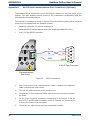
3.6
Monitor – Reading the Displayed Value Using Modbus RTU Over RS232
It is possible to communicate with the online monitor using Modbus RTU over RS232.
The monitor has a three pin serial port connection on the back – the required cable can
be supplied by Kahn (see Appendix B for set-up information).
To read the value displayed on the monitor a byte array must be created, containing
the following bytes:
Instrument
Address
Command
Reg
Address
High
Reg
Address
Low
Number
of Reg
High
Number
of Reg
Low
LRC
CRC
0x01
0x04
0x00
0x00
0x00
0x01
0x31
0xCA
Send this to the instrument with the correct delays between characters:
Baud Rate (bps)
Min Delay (ms)
Max Delay (ms)
1200
2400
4800
9600
19200
9.17
4.59
2.30
1.15
0.57
13.76
6.88
3.44
1.72
0.86
After a few seconds the instrument will send back the following response:
Instrument
Command
Address
Number of Display
bytes
High
Display
Low
LRC
CRC
0x01
0x02
0x67
(Varies)
(Varies)
0x03
0x00
Data MSB * 256 + Data LSB = 0 *256 + 103 = 103
This code, written in c, can be used to convert the 103 into a real dew-point value or
10.3:
float ConvertToReal(int Value) //convert dew-point value to real dew-point result
{float result; //declaration
if (Value > 32767) Value=(Value-65536); //convert to negative number
result = (float)(Value/10.0); //divide number by 10 to convert to float
return result; //return real value}
38
March 2014
Easidew Online User’s Manual
4
MAINTENANCE
GOOD MEASUREMENT PRACTICE
The Easidew Online Hygrometer is designed to operate in a flowing gas stream and is
suitable for the measurement of the moisture content of a wide variety of gases. In
general, if the gas (in conjunction with water vapor) is not corrosive to ceramics or base
metals then it will be suitable for measurement by the Easidew Online.
The transmitter is designed for operation with sample gas flow rates of 2-10 scfh (1-5
Nl/min) (sample block), 1-10 s/min (direct connection). Ideally, the flow rate should
be set-up between 8.5 and 12.7 scfh (4 and 6 Nl/min), (10.6 scfh (5 Nl/min) is the
recommended optimum. Flow regulation is not provided within the Easidew Online
system. Sample gas flow must therefore be regulated outside the instrument; on the
input side of the sample block by means of a precision needle valve. Always use high
quality valve gear, coupling connections and tubing.
The transmitter will operate successfully at flow rates within its operational range and
it is important to insure that the flow rate through the sample block is high enough to
avoid long time lags in response to humidity changes at the sample source.
Avoid pressure gradients in the system by placing excessive flow restriction on the
output side of the sample block. In applications where the test gas has a very high flow
rate, an instrument by-pass arrangement is preferable to a flow restriction after the
transmitter.
Kahn Instruments
39
Easidew Online User’s Manual
MAINTENANCE
4.1
General Operational Guidelines
General guidelines to be followed when setting-up a sampling system are as follows:
•
Transmitter Positioning
The sample point should be as close to the critical measurement point as possible. Also,
never sample from the bottom of a pipe as entrained liquids may be drawn into the
sensing element.
Figure 30
•
Installation Location
Avoidance of Dead Spaces
Dead space causes moisture entrapment points, increased system response times and
measurement errors, as a result of the trapped moisture being released into the passing
sample gas and causing an increase in partial vapor pressure.
Deadspace
Figure 31
•
Indication of Dead Space
Particulate and Oil Removal
Particulate matter at high velocity can damage the sensing element and similarly, at
low velocity, they may ‘blind’ the sensing element and reduce its response speed. If
particulate, such as degraded desiccant, pipe scale or rust is present in the sample gas,
use an in-line filter.
•
High Quality Tube and Fittings
Kahn Instruments recommends that, wherever possible, stainless steel tubing and
fittings should be used. This is particularly important at low dew points since other
materials have hygroscopic characteristics and adsorb moisture on the tube walls,
slowing down response and, in extreme circumstances, giving false readings. For
temporary applications, or where stainless steel tubing is not practical, use high quality
thick walled PTFE tubing.
March 2014
40
Easidew Online User’s Manual
•
MAINTENANCE
Complexity avoidance (tee pieces, in-line couplings, etc.)
Sample tubing should, ideally, be specially designed for each application rather than
adapted from that previously installed for another application. Dead space in sample
lines increases response time by holding water molecules which are more slowly released
to the passing gas sample.
•
Sample Gas Selection
Generally, if the sample gas (in conjunction with water vapor) is not corrosive to base
metals, it will be suitable for measurement by the Easidew Online system. Gases
containing entrained solids should be filtered before application to the sample block.
Care should be taken with gas mixtures containing potentially condensable components
in addition to water vapor, e.g. oil, to insure that only water vapor is present in the
sample.
4.2
Maintenance and Calibration
Routine maintenance of the Easidew Online Hygrometer is confined to regular recalibration. For most applications, annual re-calibration insures that the stated accuracy
of the Easidew Online Hygrometer is maintained.
Specialized calibration instrumentation is required to calibrate the transmitter and a true
calibration can only be performed by exposure of the dew-point sensor to a reference
gas of known dew point.
Calibration services are offered by Kahn Instruments. All calibrations are traceable to
the National Institute of Standards and Technology (USA).
The Easidew transmitter can be returned to Kahn Instruments for calibration at 13
points across the dewpoint range -148 to +68°Fdp (-100 to +20°Cdp).
Alternatively, Kahn Instruments can provide an exchange transmitter. Prior to recalibration, an exchange transmitter can be ordered from Kahn Instruments.
Once the replacement transmitter and calibration certificate have been received, the
original transmitter can be disconnected from the sample line and the monitor and
the replacement transmitter installed in its place. Refer to Section 2.1.1. The original
transmitter should be packed in its original packing (see Figure 3) and returned to Kahn
Instruments.
Easidew transmitters are fully interchangeable and can be used with any Easidew Online
monitor. Transmitter interchangeability is not affected by cable length.
4.2.1
Clean Monitor
The front panel of the monitor should be cleaned with a moist lint free cloth. Mild
detergent may be used to remove any stubborn marks or stains but DO NOT use any
type of solvent, e.g. acetone, which could damage the instrument.
Kahn Instruments
41
Easidew Online User’s Manual
MAINTENANCE
4.3
Fault Conditions
Message
Displayed
ErrL
Cause
Sensor failure
Instrument failure
Sbr
ErrH
Action
Check power supply to transmitter. Check
transmitter cable for continuity/damage.
Rectify/replace cable
Refer to Kahn Instruments for repair
Check transmitter cable for continuity/
Sensor failure or break in
damage.
sensor connection
Rectify/replace cable
Gas is wetter than +68°Fdp
Check gas source supply
(+20°Cdp)
Sensor contaminated
Replace/re-calibrate transmitter
outR
Input out of range
Check gas source supply.
Re-calibrate/replace transmitter
rurC
Reverse input connection
Swap input connections
transmitter to the monitor
from
the
42
March 2014
Easidew Online User’s Manual
APPENDIX A
Appendix A
Technical Specifications
Kahn Instruments
43
Easidew Online User’s Manual
APPENDIX A
Appendix A
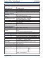
Technical Specifications
Monitor
Performance
Measurement Range
(Dew Point)
-148 to +68°F (-100 to +20°C) dew point
Electrical Specifications
Input Signal
Output Signal
Alr 1 Relay
Alr 2 Relay
Output
Analog Output Scaled
Range
Power Connection
Supply Voltage
Over Voltage Category
Display
Temperature and Alarms
Indicators
Load Resistance
Current Consumption
Power Connection
Transmitter Cable
4-20 mA input from Kahn dew-point transmitter
4-20 mA (or –20mA) (2-wire connection, current source)
User configurable over range
Single pole make contact, rating 3 A @ 250 V AC
Changeover contacts, rating 5 A @ 250 V AC
Dew point or moisture content for ppmV
Dew point: -148 to +68°F; -100 to +20°C
Moisture content in gas: 0-3000 ppmV
Non-standard available upon request
2 wire, length 2m (6.6ft)
100 to 240 V AC (+10%, -15%), 50/60 Hz
(Optional 24 V DC) (-15%, +10%) 6W
III, fixed installation category
20.3mm red 4 digit LED display
Red LED’s
Max 600 Ω
AL1, AL2, °C, °F
60 mA max
Copper braid screened cable; 4 core 7 / 0.2 (0.22mm²), stranded,
tinned copper conductors, PVC, insulated, Melinex taped, Black PVC
outer. Max length 800m (2,624 ft)
Operating Specifications
Environmental Ratings
Standard, indoor at an altitude of less than 6000 feet with noncondensing humidity
+32 to +122°F (0 to +50°C) 90% RH max (non condensing)
Continuous
Operating Temperature
Operating Mode
Mechanical Specifications
Ingress Protection
NEMA 4X (IP65) at front, IP20 at rear
Housing Material
1/8 DIN 43700 plastic housing
Dimensions
3.8 x 1.9 x 3.4” (96 X 48 x 86.5mm) horizontal
Mounting
Panel mounting (cut out 3.6 x 1.8” (92 x 46mm))
Weight
Approximately 7.4oz (210g)
March 2014
44
Easidew Online User’s Manual
APPENDIX A
Transmitter
Performance
Measurement Range (Dew Point) -148 to +68ºFdp (-100 to +20ºCdp)
Accuracy (Dew Point)
±3.6ºFdp (±2ºCdp)
Response Time
5 mins to T95 (dry to wet)
Repeatability
0.9ºFdp (0.5ºCdp)
Calibration
13 point calibration with traceable 7 point calibration certificate Electrical Specification
Output Signal
Output
Analog Output Scaled Range
Supply Voltage
Load Resistance
Current Consumption
CE Marked
4-20 mA (2-wire connection current source)
User-configurable over range
Dew point or moisture content for ppmV
Dew point: -148 to +68ºF (-100 to +20ºC) OR
Moisture content in gas: 0 - 3000 ppmV
Non-standard available upon request
12 to 28 V DC
Max 250 Ω @ 12 V
(500 Ω @ 24 V)
20 mA max
Certified
Operating Specifications
Operating Temperature
Operating Pressure
Flow Rate
Temperature Coefficient
-40 to +140ºF (-40 to +60ºC)
5000 psig max
2 to 10 scfh (1 to 5 Nl/min) mounted in standard sampling
block;
0 to 10 m/sec (0 to 33 fps) direct insertion
Temperature compensated across operating temperature range
Mechanical Specifications
Ingress Protection
Housing Material
Dimensions
Sensor Guard
Process Connection & Material
Weight
Interchangeability
Electrical Connection
Diagnostic Conditions (factory
programmed)
Digital Diagnostic
Communications
IP66 in accordance with standard BS EN60529:1992
NEMA 4 in protection accordance with standard NEMA 250-2003
316 stainless steel
Transmitter plus connector
L=5.19” x ø1.77” (132mm x ø45mm)
Standard: HDPE Guard < 10µm
Optional: 316 stainless steel sintered guard < 80µm
5/8” - 18 UNF
316 stainless steel
5.29oz (150g)
Fully interchangeable transmitter
Hirschmann GDS series (DIN 4350-C)
Condition
Output
Sensor fault
23 mA
Under-range dew point
4 mA
Over-range dew point
20 mA
RS485, 2-wire Modbus RTU
Kahn Instruments
45
Easidew Online User’s Manual
APPENDIX A
Dimensions
1/8” NPT
132mm
(5.19”)
46mm
(1.81”)
10mmø27mm
(0.39”)
ø25.4 x 2mm
(ø1 x 0.07”)
(1.06”)
27 A/F
5/8” 18 UNF
1/8” NPT
10mm
(0.39”)
Transmitter
5/8” Bonded Seal
1/8” NPT
ø25.4 x 2mm
(ø1 x 0.07”)
55.2mm
2.2”
1/8” NPT
m
9”)
5/8” Bonded Seal
5/8”-18 UNF
5/8”-18 UNF
Sample Block
48mm
(1.9”)
44mm
(1.73”)
96mm
(3.7”)
10.5mm
(0.41”)
94mm
(3.7”)
Easidew Online
SIDE VIEW
FRONT VIEW
Hygrometer
76mm
(3”)
92mm
(3.6”)
46mm
(1.8”)
5/8” 18 UNF
27 A/F
30mm
1.18”
46mm
(1.81”)
ø30mm
ø1.18”
OVERLAY
TOP VIEW
Monitor
Figure 32
Dimensions
March 2014
46
55.2mm
2.2”
Easidew Online User’s Manual
APPENDIX B
Appendix B
RS232 Data Communications
Port Connections (Optional)
Kahn Instruments
47
Easidew Online User’s Manual
APPENDIX B
Appendix B
RS232 Data Communications Port Connections (Optional)
The Easidew Online instrument has an RS232 port, situated on the rear panel of the
monitor. This port enables remote access to the instrument’s configuration and the
indicated dew-point temperature.
The method of connection is shown in Figure 33 and the following items will be required
(these are not supplied with the Easidew system):
•
Matching connector for monitor output port
•
Screened RS232 communications cable (max length permitted 40ft (12m))
•
9-pin, D-Type RS232 connector
Tx
Tx
Rx
Rx
9
8
GND
2
3
7
GND
1
6
4
5
9 Pin D-Type Connector
Process Indicator
Rear Panel
Figure 33
RS232 Connections
1.
Strip both ends of the communications cable to expose the individual
cable cores and the cable screen.
2.
Trim off the cable screening at the monitor end.
3.
Connect the Tx, Rx and ground (GND) cable cores to the monitor connector
as shown.
4.
On the 9-pin D-type PC connector, connect the Tx line to pin 3, the Rx
line to Pin 2 and the GND connection to Pin 5. Connect the Screen to Pin
5 and/or the frame of the connector.
5.
Check that the cable wiring has been completed correctly.
48
March 2014
Easidew Online User’s Manual
APPENDIX C
Appendix C
UL Certification
Kahn Instruments
49
Easidew Online User’s Manual
APPENDIX C
Appendix C
UL Certification
Below are listed the requirements of UL Certification:
Standards:
UL 61010-1, 2nd edition, 2005-07-22 (Electrical
Equipment for Measurement, control, and laboratory
use: Part 1: General requirements)
CAN/CSA-C22.2 No. 61010-1 2nd edition, 2004,-07,
(Electrical Equipment for Measurement, control, and
laboratory use: Part 1: General requirements)
Temperature: Maximum ambient temperature rating +50°C (+122°F)
Maximum Relative Humidity: 95%
Power Supply Source: To be powered by a certified NEC Class 2 or LPS output
power supply source or equivalent.
Pollution Degree: 2
50
March 2014