1
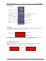
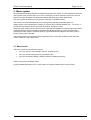
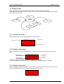
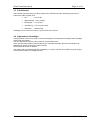
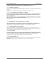
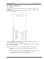
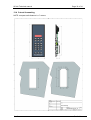
SC4x0 Technical manual
Page 1 of 34
SC4x0 Technical manual
Abstract:
This document is the technical manual for:
- SC410, a high-end flush mount telephone for wheelhouse & ECR.
-SC420, a high-end bulkhead mounted heavy-duty telephone for E.R. etc.
Doc ID:
Revision history
Date
D.Rev.
S.Rev.
Init.
Comment
2008 05 28
01.00
080409
LAF
Document created...
2008 11 12
01.01
081106
LAF
Document updated to new hands free funk.
2009 10 07
02.00
091007
LAF
Busy detect, local external mode
SeaCom
Rev 2.00
SC4x0 Technical manual
Page 2 of 34
Technical Manual
-SC410 / SC420
- P410 / P420
SeaCom
Rev 2.00
SC4x0 Technical manual
Page 3 of 34
Contents
1.
INTRODUCTION .............................................................................................................6
1.1
Purpose and Scope ....................................................................................................6
1.2
Required approval information....................................................................................6
2.
Overview .........................................................................................................................7
2.1
Display ........................................................................................................................7
2.2
Display -Power on info ................................................................................................7
3.
Menu system ...................................................................................................................8
3.1
Menu levels.................................................................................................................8
3.2
Display modes ..........................................................................................................10
3.2.1
Display –Idle mode ............................................................................................10
3.2.2
Display –Busy mode ..........................................................................................10
3.2.3
Display –Error mode ..........................................................................................10
3.3
Call indicator .............................................................................................................11
3.4
Light sensor & backlight............................................................................................11
4.
Data & control signals from the exchange.....................................................................12
4.1
Line voltage & ringing voltage detector.....................................................................12
4.2
16 kHz control signals...............................................................................................12
4.3
FSK / CLIP data ........................................................................................................12
5.
Hidden menu .................................................................................................................13
5.1
System info ...............................................................................................................13
5.1.1
Device & software family ...................................................................................13
5.1.2
Serial number ....................................................................................................13
5.1.3
Production date .................................................................................................13
5.1.4
System state ......................................................................................................13
5.1.5
E bank ...............................................................................................................14
5.1.6
Error code ..........................................................................................................14
5.2
Monitor line ...............................................................................................................14
5.3
Monitor input .............................................................................................................15
5.4
Set parameter xx ......................................................................................................15
5.5
Recall factory ............................................................................................................15
5.6
Erase eeprom ...........................................................................................................15
5.7
Reset ........................................................................................................................15
5.8
Sys test .....................................................................................................................15
6.
Protective measures......................................................................................................16
6.1
Reverse voltage ........................................................................................................16
6.2
Excessive voltage .....................................................................................................16
6.3
Excessive temperature .............................................................................................16
6.4
Program deadlock protection ....................................................................................16
6.5
PCB coating ..............................................................................................................16
7.
Audio path & voice control.............................................................................................17
7.1
Acoustic considerations ............................................................................................17
SeaCom
Rev 2.00
SC4x0 Technical manual
7.2
8.
Page 4 of 34
Voice control considerations .....................................................................................17
Electrical layout .............................................................................................................18
8.1
Example of a simple set up with headset .................................................................18
8.2
Example of a simple set up with handset .................................................................19
8.3
Example of set up with remote PTT for loudhailer ....................................................19
8.4
Ground & shield connections ....................................................................................19
9.
Mounting & programming ..............................................................................................20
9.1
Power supply & grounding considerations................................................................20
9.2
Programming the type of headset & VOX .................................................................20
9.3
Adjusting microphone gain .......................................................................................20
9.4
Relay function ...........................................................................................................21
9.5
Dial signal type .........................................................................................................21
9.6
Hands free voice control ...........................................................................................21
9.7
Bell signal and volume ..............................................................................................21
9.8
PA volume ................................................................................................................21
9.9
External speaker .......................................................................................................22
9.10
Adjusting external dimmer input ...............................................................................22
9.11
Local external microphone........................................................................................22
10.
Parameter list ................................................................................................................23
10.1
Level 1 parameters ...................................................................................................23
10.2
Level 2 parameters ...................................................................................................23
10.3
Level 3 parameters ...................................................................................................24
10.4
Parameter list for hidden menu.................................................................................25
11.
Serial monitor ................................................................................................................27
11.1
Function ....................................................................................................................27
11.2
Commands ...............................................................................................................27
11.3 Commands use full for workshop testing ..................................................................27
11.3.1 Set Relay -command .........................................................................................28
11.3.2 To pass audio from microphone to speaker ......................................................28
11.4 Commands use full for development & testing .........................................................28
11.4.1 Memory monitor & manipulation ........................................................................28
11.4.2 Eeprom data ......................................................................................................28
11.4.3 Busy tone detector.............................................................................................28
12.
Simple faultfinding .........................................................................................................29
12.1
No ‘life sign’ ..............................................................................................................29
12.2
Spontaneous reset....................................................................................................29
12.3
Unable to hang up in hands free mode.....................................................................29
12.4
Noisy or scratchy sound quality ................................................................................29
12.5
No direct in, no PA or no command call ...................................................................29
12.6
Dialing problems .......................................................................................................29
12.7
Low or distorted sound from microphone .................................................................29
SeaCom
Rev 2.00
SC4x0 Technical manual
13.
Page 5 of 34
Technical specifications ................................................................................................30
13.1 Connectors ...............................................................................................................30
13.1.1 Power ................................................................................................................31
13.1.2 PE protective Earth............................................................................................31
13.1.3 Line ....................................................................................................................31
13.1.4 Dimmer ..............................................................................................................31
13.1.5 Handset & cradle ...............................................................................................31
13.1.6 Relay output ......................................................................................................31
13.1.7 External speaker................................................................................................31
13.1.8 Headset .............................................................................................................32
13.1.9 Cable & terminals ..............................................................................................32
13.2
General environmental data .....................................................................................32
13.3
I/O & signaling interface............................................................................................32
13.4
Cutout & mounting ....................................................................................................33
SeaCom
Rev 2.00
SC4x0 Technical manual
Page 6 of 34
1. INTRODUCTION
1.1 Purpose and Scope
This document is intended to give detailed information on the SC4x0/P4x0 telephone during
installation. Information given here is intended for skilled service engineers and if not use
correct, could lead to possibly malfunction.
This manual cover installation and setting up the telephone e.i. adjusting parameters etc.
1.2 Required approval information
P410 is an alias for SC410, P420 is an alias for SC420, where SC is short for SeaCom and P
is Phone( Alphatron label).
•
The SC410 is intended for desk mounting in protected areas.
•
The SC420 is intended for bulkhead mounting in protected areas.
•
SC410 & SC420 are designed according to IEC 60945.
•
Keypad is according to ITU-T E.161
•
Compass safe distance: >7m.
•
Software ID. : 2007001
•
Software rev.: 091007
•
All produced units are marked with type id and serial number.
WARNING
Do not disassemble the device as high voltage may present on the PCB or terminals.
Telephone line signal may contain voltage ranging from 48Vdc up to 130Vac peak.
Always switch off ALL power or disconnect ALL terminals before disassemble.
DO NOT REMOVE PROTECTIVE EARTH (PE) when device is operational.
ONLY CONNECT POWER TO SUPPLY TERMINALS & RELAY TERMINALS.
IF SUBJECTED TO EXCESSIVE CURRENT PCB MAY CATCH FIRE, THEREFOR
ALWAYS USE FUSED POWER SUPPLY ESPECIALLY ON RELAY TERMINALS.
PROTECTIVE MEASURES ARE TAKEN TO PROTECT THIS EQUIPMENT.
DEVICE WILL TRY TO DISCONNECT IT SELF BY SHORTING THE SUPPLY VOLTAGE IF
IT EXCEEDS 33V.
DEVICE WILL TRY TO DISCONNECT IT SELF BY SHORTING THE SUPPLY VOLTAGE IF
CONNECTED WITH REVERS POLARITY.
DEVICE IS INTERNALLY SEQURED BY A THERMAL FUSE OF 1.5A, HOWEVER. PEAK
CURRENT EXCEEDING 1.5A WILL OCCUR UNTIL FUSE IS TRIPPED.
SeaCom
Rev 2.00
SC4x0 Technical manual
Page 7 of 34
2. Overview
Local Speaker
Display
Speed dial / Function keys
Menu key
Mem dial key
Vol. / Backlight
Menu navigation
Call indicator
Light sensor
Numeric keys
Local Mic.
Redial / Pause
R‐key
Hands free Key
Speaker key
Local PTT
2.1 Display
The display is a 3 line 16 char dot matrix display with adjustable red backlight & automatic temperature
compensated contrast control. Display is shown in idle mode.
Date & time
11/01 23:18
2
Status field
Info field
SPD1
SPD2
SPD3
Function key text
Display always revert to Idle mode after a general time out of 10 sec. When timing out, current process
is canceled. If timeout occurs during programming, data is lost and old data is restored.
2.2 Display -Power on info
When the phone is in power on state it will show information about hardware and what software it is
running.
4 sec. after power on display will enter idle state unless no line is detected.
HW Rev.
SW Rev.
SW ID..
SeaCom
01
080104
2007001
After 4 sec.:
00/00 00:00
SPD1
SPD2
SPD3
Rev 2.00
SC4x0 Technical manual
Page 8 of 34
3. Menu system
All adjustments and setup changes are made through the menu system. It is only possible to enter the
menu system if the phone is idle or if no line is connected. If a call is received or if phone is off hook
(active), all menu processes are aborted and display will show idle or busy status menu.
The menu system is divided in to two sections, user section & hidden section.
User section can be accessed directly from the keypad by pressing and holding down ‘M’.
Hidden section can be accessed by pressing ‘R’ 5 times with an interval between 0.5 – 1.0 sec on. If
another key is pressed or time is not within the window, operation is reset.
When the menu system is active and no keys are pressed, all operations will be canceled after 10 sec.
If data was being entered, operation is canceled and old data restored. If a call is received while
operating the menu system, immediate timeout is generated and the telephone will revert to idle to
show incoming call or idle state.
A few special menus are excepted from the general timeout. These are the dial function and some
monitor functions in the hidden menu.
3.1 Menu levels
There are 3 levels in the main menu system.
•
Level 1 is common used settings. (volume, ringer level etc.)
•
Level 2 is primary settings (memory dial setting etc.)
•
Level 3 is secondary settings. (Settings used for installing the phone)
There is one level in the hidden menu.
If more detailed information re. the menu system is required, please refer to user’s manual.
SeaCom
Rev 2.00
SC4x0 Technical manual
Page 9 of 34
Level 1: EXIT
Speaker volume
Backlight
Ringer volume
P.A. volume
Bell signal
Calls out
Calls in
SET_UP_MENU
Level 2:
Level 3:
Main Menu
Auto answer
Auto busy
Direct in
Hands free
External speaker
Date & Time
Speed dial
Memory 1-6
Special menu
SET_UP_MENU
Dial signal
Loop dial type
Remote PTT
Remote Hook switch
Lcl Ext Mic
Headset type
Headset VOX.
Gain local microphone.
Gain handset microphone.
Gain headset microphone.
Gain external microphone. (loudhailer)
Relay mode.
Relay hold off.
Contrast (display)
Hidden menu: System Info
Monitor line
Monitor input
Set param. XX.
Recall Factory.
Erase EEPROM
Reset
Sys. test
SeaCom
Rev 2.00
SC4x0 Technical manual
Page 10 of 34
3.2 Display modes
When display is not used for display the menu system it will enter idle state or mode.
Idle mode is the initial display mode or basic mode. From idle mode it can enter dial mode, busy mode,
error mode or menu mode.
Power
Idle mode
Menu System
Error
Dial mode
Busy mode
3.2.1 Display –Idle mode
When the telephone is in idle, display will show the following info.:
Date & time
11/01 23:18
SPD1
SPD2
Status field
2
SPD3
Function key text
3.2.2 Display –Busy mode
When the telephone is in conversation mode e.i., the phone is busy, display will show the following
info.:
Real time clock
Audio connection
10/27 14:08 HS*
00:12:35
LOCAL
Status field
Leap time
If mute state, speaker or hands free changes, status field is updated.
If change to another audio connection e.g. handset is made, it will be shown in the display.’
3.2.3 Display –Error mode
When the telephone detects missing line, it will enter error mode. Here the cause of current error will
be shown as flashing text or error code. Currently, only line error exits.
00/00 00:00
No Line
SeaCom
Rev 2.00
SC4x0 Technical manual
Page 11 of 34
3.3 Call indicator
Call indicator has two purposes. Primary purpose is to indicate line state. Secondary purpose is to
indicate lost calls & system error.
•
Off…………...: Line is idle.
•
Rapid flashing.: Line is ringing.
•
Steady light…: Line is busy.
•
1Hz flashing...: Line or system fault.
•
Short flash…..: Missed calls.
If flashing, but no line error is shown, a system error has occurred.
3.4 Light sensor & backlight
The light sensor in the front is used to control the backlight in the keyboard and display when backlight
mode is set to automatic.
The raw data from the sensor can be read out via the hidden menu.
If two units are placed side by side and dimming is controlled externally, dimmer input needs to be
calibrated for the two units to have same intensity.
NOTE: External dimmer is optional
The display and the keyboard light are controlled by a common function and variation in power supply
will a minimum impact on backlight intensity.
SeaCom
Rev 2.00
SC4x0 Technical manual
Page 12 of 34
4. Data & control signals from the exchange
Signals & data are sent from the exchange in different ways. Control signals are issued as 16kHz
burst, where the duration and current state of operation determine how to interpret date. CLIP signals
(Caller Line Information) are issued using FSK.
Line voltage is used to indicate ringing, busy or idle.
4.1 Line voltage & ringing voltage detector
The line interface fund in drawing SCH061212LAF01_xxx page 2 of 3 shows the line interface.
Line voltage and polarity is measured by the processor via U2A and the voltage divider placed across
the line.
Line Voltage
>25 volt dc
Line is idle
<18 volt dc
Line is busy
<5 volt dc
No line
If AC voltage >25Vac @50Hz is detected (pure AC or AC on top of DC), ringing is detected.
There is a 200ms delay before a valid change of state is detected.
4.2 16 kHz control signals
The line interface fund in drawing SCH061212LAF01_xxx page 2 of 3 shows the line interface. 16kHz
signals are filtered through the high pass filter and passed into the detector. The detector input is
compare to a DC level set by the processor. From the hidden menu system, it is possible to adjust
trigger level for the detector. Only I rare cases where noise is disturbing the detector, adjustment of the
16 kHz threshold level is needed or if the detector needs to be disabled. Setting the level to 0% or
100% will disable the detector.
4.3 FSK / CLIP data
If the exchange is programmed to issue FSK data, caller’s ID can be displayed. Data is sent in a single
burst of 575 ms from the exchange, 500ms after first ring signal. FSK data is decoded by U19 and sent
as 1200 baud data 8N1 to the processor. The processor’s UART 1 picks up any FSK data. Up to 20
digits and 50 chars can be sent as caller’s number & name in a single message. The telephone will,
however show the last 16 digits only of the number and the 16 first chars of the name.
The telephone needs no power on / wake up ringing signal as it runs on constant power and never
enters any power down mode. This means data can be received without the need of an alert ringing or
signal sequence.
NOTE: Only month and day data is defined in the time data frame for CLIP data. If year info is needed,
it must be keyed in manually from the menu system. The internal RTC use year info for leap year info.
Default year will be 00. This will have a potential impact on the date shift from 28->29 of feb.
SeaCom
Rev 2.00
SC4x0 Technical manual
Page 13 of 34
5. Hidden menu
This menu is hidden, as all items in this menu are intended for service or setting up the unit. Some
settings in this menu can possibly cause the unit to malfunction e.g. setting audio gain to line to 0.
The menu access is protected by a times key sequence. The ‘R’ button must be pressed 5 successive
times at an interval of 0.5 – 1 sec. If timing is not right, the 5 time counter will reset.
5.1 System info
This sub menu item displays the following items:
•
Device & software family
•
Serial number
•
Production date
•
System state
•
E_Bank
•
Error code
5.1.1 Device & software family
This item has partly been replaced by the power up menu, but will show in plain text the basic type of
device.
5.1.2 Serial number
This item is the device unique serial number. If this number is missing, error is indicated via the call
indicator flashing and an entry is made to the internal error log.
5.1.3 Production date
This item shows the production date of the device. It should be on the format YY/MM.
5.1.4 System state
This item shows current device state. If an unrecoverable error is detected, device will enter error state
and start flashing the Call indicator.
It should read ‘2’ for normal.
State code
SeaCom
State
0
Reset (debugging)
1
Boot (debugging)
2
Normal
3
Programming
4
Error
5
Manual (debugging)
Rev 2.00
SC4x0 Technical manual
Page 14 of 34
5.1.5 E bank
This item shows current NOV memory error info. If a check sum error is detected in an eeprom
memory bank, error state is entered and the ID of the last failed bank will be shown here.
5.1.6 Error code
If an error is detected, a new entry is made to the error log and last entry is shown here. If the device is
giving error indication, the cause should be identified here.
Each system error has a unique binary indicator. If more errors are present, error code will represent
the sum of all errors. The value 0 is no errors.
E.g. if error 0x0001 and error 0x0002 is both active, error code will show 0003
Error code
Cause
Function
0001
RAM error
Set error state
0002
Check sum error
0004
NOV memory error
0008
Temperature alarm
(set if board temp. >
80°C)
0010
Temperature warning
(set if board temp. >
70°C)
Switch off all backlight
Decrease speaker vol.
to step 7. (44%)
0020
No serial number
Set error state
0040
Watch dog error
Set error state
0080
IRQ time too long
Set error state
5.2 Monitor line
This item will monitor all line events. This menu will not exit idle when hook off or timeout. It is possible
to press ‘Speaker’ to go off hook or to call the phone.
Following items will be monitored. Display will update on change only
Line voltage:
Numerical value from 0 to 63 volt.
Line polarity:
Tip > Ring : 1, If Ring > Tip : 2. NOTE Voltage must be out of 5V dead band.
Line state:
-Idle
-busy
-ring
-NC
16 kHz signal: -Vol.
Indicating volume override (PA call).
-PA.
Indicating normal PA call
-Term. Termination of ongoing sequence or cancel call.
-HOFF. Hook Off command (used for command / group call with direct in)
-HON. Hook On command (used for init of device or cancel command call)
-DIRECT
Direct in call
SeaCom
Rev 2.00
SC4x0 Technical manual
Page 15 of 34
5.3 Monitor input
This item is mainly used for testing hardware. It will show input values from PTT, HOOK & sensors.
Temperature: -20 - +90°
Dimmer input: 0 – 100%
Light sensor: 0 – 100%
Displays actual board temperature.
Displays actual external dimmer input level.
Displays actual light sensor level.
If signal from headset PTT or handset hook switch is detected, display will show coherent text.
5.4 Set parameter xx
This item is used to adjust all hidden parameters not accessible from the main menu system. Each
parameter is given as id number. The number can be found in the section ‘Parameter list for hidden
menu’.
First key the number of the parameter to change. When pressing ‘M’, display will show current value
for that parameter. If the value is not to be changed, just press ‘M’ to return. If a change is requested,
key in a new value using 0-9. If range is 0-9, only one digit can be entered. To enter the new value,
press ‘M’.
If the new value is out of range, data will be replaced by high or low boundary value.
Depending on the type of data, ‘.’ Or ‘-‘ can be entered using the F-keys. F3 will erase last entered
digit.
5.5 Recall factory
This function will clear all user settings and restore them to factory values.
Use this function if there is any doubt re. current settings, to set all parameters.
From software 090928, all new parameters will automatically preset to factory values on first power up
after software update.
When updating software, it is always a god idea to note deviations from factory settings before
recalling.
Especially if adapted for special use.
NOTE: memory & speed dial data will NOT be erased by this function.
5.6 Erase eeprom
This function will erase all settings, all speed dial data, all mem dial data and call logs and cause the
unit to reload factory settings to all parameters on first power up
5.7 Reset
This function will cause the device to restart as if power was recycled. Use this function to read current
software rev., hardware rev or software id from the power up menu.
5.8 Sys test
This function will engage a small test sequence to test alarm relay and display.
Will revert to idle after 10 sec.
SeaCom
Rev 2.00
SC4x0 Technical manual
Page 16 of 34
6. Protective measures
6.1 Reverse voltage
The device is protected against wrong polarization of the supply voltage. In the supply line a protective
diode is connected across in non-conducting direct when connected right. When connected in reverse,
this diode will short through a PTC fuse and interrupt the supply current.
Supply must be disconnected for a few seconds before the fuse resets.
6.2 Excessive voltage
The device is protected against high voltage from e.g. battery charger. If the supply voltage exceeds
approx 33.5 volt a crow bar circuit will short the supply through a PTC fuse. This will either blow the
external fuse or lower the internal supply to below 0.5 volt until supply is disconnected.
Supply must be disconnected for a few seconds before the fuse resets.
6.3 Excessive temperature
If the board temperature exceeds 70°C a warning is given to the internal alarm log and error condition
is indicated by the ‘Call’ indicator.
If the temperature exceeds 85°C an alarm is given, backlight supply is disconnected if the unit is active
volume is lowered to step 7 if set higher for reducing the power dissipation.
When temperature of the power amplifier reaches approx 140°C it will shut down due to thermal
protection.
6.4 Program deadlock protection
The processors internal watchdog that is enabled at a rate of 106ms protects the device software.
It is only serviced by the main loop and a few time-consuming inline functions. In case software
accidental or by electrical noise injection enters a deadlock a timeout will occur and reset the
processor.
In parallel to that, an optional external watchdog can be enabled by means of a jumper in J7. If a
jumper is located in pos no. 3 from left to right, the watchdog is enabled. If the jumper is omitted, it is
disabled.
The external watchdog is for future implementing of PA and other options requiring an independent
monitor source and is have a service timeout of 1,6 sec.
6.5 PCB coating
The PCB is coated to protect it from the harsh environment at sea.
SeaCom
Rev 2.00
SC4x0 Technical manual
Page 17 of 34
7. Audio path & voice control
Below a schematic of the audio path is shown.
Line
Handset
Handset
Local
CODEC
Headset
Local
yP control
Ext. speaker
Headset
All audio is passed through the codec for signal processing. Volume control of the speakers and pregain control of the microphones are all made via processor control. There are no mechanical
adjustable.
All microphone inputs are balanced inputs for maximum noise suppression.
7.1 Acoustic considerations
To select the right setup for the installation is important to optimum sound quality.
In general, hands free works best in quiet areas, but if an external speaker is added it could be
functional in areas with moderate ambient noise.
If installed in areas with a very high level of ambient noise, headset is the only right solution.
Care should be taken to select headset or handset capable when making installations in high noise
areas.
If the microphone sensitivity is too high, it might suffer from signal saturation or cause the input to
suffer for saturation.
Location
Ambient noise
level
Operation
Bridge, Offices, Mess, etc Low
Hands free, handset.
Voice control: 10dB .. 25dB
ECR, Galley, SCC
Medium
Hands free, handset, possibly assisted by
external speaker.
Voice control: 30dB .. 40dB
ER, SGR, Generator
High
Handset, headset.
Thruster, Hydraulics
Very high
Headset and in some cases handset.
7.2 Voice control considerations
To get optimum performance from the automatic voice control when using hands free, the level of
speech must be approx. 10dB above background noise level. If not, voice control cannot detect voice
from noise and thus control direction of speech.
This is very important when using headset or hands free in every noisy areas, especially when using
headset in extreme noisy areas in one end and hands free at the other end, even more if combined
with VOX for the headset.
To be able to go above the background noise level, may require a high sound pressure that will
saturate the microphone input if the microphone is too sensitive or if the gain is too high.
SeaCom
Rev 2.00
SC4x0 Technical manual
Page 18 of 34
8. Electrical layout
Below a schematic of the electrical layout is shown.
DC/DC
Power Amp.
+5V
+24V
PTT
Speakers
0V
Mic.
Hook SW
Line
Hook SW 0V
0V
Tip
Dimmer
Ring
Frame
PE
The drawing below shows all connections and number of wires.
6
2
2
Ext. speaker / Loudhailer
Handset
Display
Keypad
+24V
Line
Dimmer
(optional)
2
6
Headset
2
2
8.1 Example of a simple set up with headset
This example shows how to connect supply & headset to the telephone.
T2A
+24V
0V
PE
SC410/420
T1A
Relay COM
To bell or alarm relay coil
NOTE: If connected to DC
coil –use protection diode.
Relay NO (or NC)
Headset Mic
Headset SP
Line
PE
Headset PTT
PE
NOTE: If shield is connected at
APBX do NOT connect to PE at
telephone end
Always only connect one end due
to possibly high ground current
when
used off shore
SeaCom
Rev 2.00
SC4x0 Technical manual
Page 19 of 34
8.2 Example of a simple set up with handset
This example shows how to connect supply & handset to the telephone.
T2A
PE
+24V
0V
Hook Sw. signal
Hook Sw. 0V
PE
SC410/420
T1A
Relay COM
To bell or alarm relay coil
NOTE: If connected to DC
coil –use protection diode.
Handset Mic
Handset SP
Cradle switch must be potential
free.
Switch must close when handset is
off hook.
Cradle Switch is connected to Hook
Sw. on telephone
If cradle have a double switch, use
the other for connecting speaker.
Relay NO (or NC)
Line
PE
NOTE: If shield is connected at
APBX do NOT connect to PE at
telephone end
Always only connect one end due
to possibly high ground current
when
used off shore
8.3 Example of set up with remote PTT for loudhailer
This example shows how to connect loudhailer in remote location
PE
T2A
Hook Sw. signal
Hook Sw. 0V
+24V
0V
PE
SC410/420
T1A
Relay COM
To bell or alarm relay coil
NOTE: If connected to DC
coil –use protection diode.
Handset Mic
Handset SP
Cradle switch must be potential
free.
Switch must close when handset is
off hook.
Cradle Switch is connected to Hook
Sw. on telephone
If cradle have a double switch, use
the other for connecting speaker.
Relay NO (or NC)
Line
Headset PTT
PE
NOTE: If shield is connected at
APBX do NOT connect to PE at
telephone end
Always only connect one end due
to possibly high ground current
when
used off shore
Ext. Speaker
PE
Headset PTT function needs to
be assigned to loudhailer PTT
from the menu system.
NOTE: When using headset
PTT for remote loudhailer,
due to noise picked up by the
cable, adding a slave relay
located next to the telephone
may prove beneficial.
8.4 Ground & shield connections
It is very important to connect or terminate all shields correct. Normally shields should be terminated to
ground or ship hull in both ends and not carry any signal (forward or return). Due to possible high
ground currents in case of earth leakage or lower shield resistance, it recommended to terminate in
one end only.
In general, power and line should be terminated at the exchange and remaining wires at the
telephone.
It is very important to connect ‘PE’ to ground or ship’s hull for protection and to avoided noise
interference. Connection between ‘PE’ and ground should be as short as possible.
SeaCom
Rev 2.00
SC4x0 Technical manual
Page 20 of 34
9. Mounting & programming
When setting up this unit, first disassemble the box if it is a 420 type.
Detach the terminals J4 & J6 by pulling them off. Connect all wires to the terminals and check power
and relay connections before attaching the terminals to the unit. Be careful not to relocate J4 at J6.
9.1 Power supply & grounding considerations
If powered from the exchange, make sure a fuse protects the unit and power supply is strong enough
to blow the fuse without shutting down the exchange. If more units are connected, make sure the
power supply has enough dynamic power to handle peak currents if external speakers are connected.
The telephone will consume approx 250mA max if no external speaker is connected. An 8ohm
speaker will take additional peak currents up to at least 1.8 amp.
Both the 410 & the 420 must have connected PE via a separate wire to a central earth/grounding
point.
9.2 Programming the type of headset & VOX
When using headset, always check the type of microphone. If it comes with an eletrect (condenser)
type, changes needed to be made to factory settings. Enter the menu system to select matching type.
Always make gain adjustments AFTER selecting type of microphone.
The headset can be used with full duplex or in PTT mode. However, in full duplex mode when
connected to another phone using hands free, some voice control may be needed to maintain control
of speech direction.
VOX will raise or lower gain towards the line for better speech detection at the hands free end. This
will enhance the speech quality by raising the gain when speaking into the headset microphone and
lower it when not. If voice switching is used at the hands free end, it will ease the detection of speech.
However, if speaking at the same time, it may difficult to hear what is said at both ends, so it requires a
little practice to learn to speak in shift for perfect connection.
9.3 Adjusting microphone gain
A key issue for best performance is correct adjusted microphone gain. This phone is designed for use
in very noisy areas but may just as well be used In quiet areas. However, this dynamic span can only
be achieved by adapting the microphone gain to the actual installation.
In most cases factory settings will work just fine. However, if used in noisy areas, gain must be
lowered to avoid distortion and signal saturation. A high level of background noise requires the user to
speak very loud.
When speaking very loud the microphone generates accordingly higher signals that not need the
same amount of gain.
For the hands free voice control to work as intended, any distortion must be eliminated. This is the
reason why microphones gain need to be adapted, especially in areas beyond normal office
conditions.
Likewise if used in quiet areas or for remote listening.
SeaCom
Rev 2.00
SC4x0 Technical manual
Page 21 of 34
To aid the adjustment, a bar graph of 11 chars is showing the actual signal level. When distortion is
detected a ‘P’ will be shown at the end of the bar.
The gain should be lowered or raised until this ‘P’ is not lit when speaking at a high nominal level
under normal working conditions.
For best performance, lower the gain by just one step when adjusted as described above.
---Local mic.-->********___ P<
>
<
Use ’▲’ or ’▼’ to select level and press ‘M’ for store and exit.
If used in quiet room for remote monitoring, raise the gain until a satisfying level is achieved at the
listener.
This may, however cause duplex conversation to become difficult, as the site telephone tends to be in
transmitting mode always. To overcome this problem either a compromise regarding the gain at the
site end must be set or PTT mode or command call mode has to be used at the site end.
This adjustment has to be made to all microphones in use.
NOTE: When adjusting the handset, remember to hold the hook switch down to access the
menu system.
9.4 Relay function
The relay function is used for external ringing indication in e.g. E.R. or for connecting a electro
mechanical bell. The relay function can be selected to give indication on telephone calls, PA calls or if
telephone is in use. The last is intended for disconnecting any local speaker for making PA calls to a
system outside the exchange to avoid feedback through the telephone.
The relay function can be programmed as inverse function is power fail indication is needed.
9.5 Dial signal type
Normally DTMF signals are use to dial numbers. However, if connected to older systems or special
adoption is needed, the telephone can be programmed to use pulse dialing (loop disconnect). Pulse
dial can selected for international or Swedish mode.
Pulse dial using earth connect mode is not possible.
9.6 Hands free voice control
If the telephone is to be used in very noisy areas, either PTT mode (manual mode) or stability margin
above 30dB should be used.
Performance can be improved by adding an external speaker to work in parallel with the local speaker
and raising the stability margin.
9.7 Bell signal and volume
There are 8 different bell signals to select from. Some are low tone some are high tone. Two have the
sound equivalent to an old mechanical bell.
The ringer has its own adjustable volume setting. The volume can be set from menu level 1.
NOTE: Setting the volume above step 11 will cause distortion of the ringer signal and may cause a
considerable current consumption from the power supply if external speaker is connected.
9.8 PA volume
There are two level of PA volume. One for normal PA call and one for PA call having volume override.
Using volume override means full volume and will bypass the PA volume setting from menu level 1.
SeaCom
Rev 2.00
SC4x0 Technical manual
Page 22 of 34
Full volume is not always practical or applicable. Therefore an absolute max volume for PA call can be
set from the hidden menu.
9.9 External speaker
The external speaker can be programmed to be on by default. It has an 1.5sec lead time delay
meaning
the first ring will only be in the local speaker.
If programmed to be on, hands free will use the external speaker by default It can always be turned on
or off manually.
9.10 Adjusting external dimmer input
When the unit is tested & shipped, it is ensured that full range can be obtained. However, an input
voltage of 28 may not give 100% brightness and 5 volt will not give 0%.
The input needs to be calibrated to the actual zero- and full-scale output from the central dimmer.
To calibrate the input, set the dimmer to zero or approx 5 volt. Go to the hidden menu and read out the
dimmer input value. Note it for later use.
Set the dimmer to max output and read out the dimmer input value from the hidden menu.
Use the following formula to calculate offset and gain factor.
AOffset = Dimmer input value in % at 5 volt.
AGain = 100 / (Dimmer input value in % at max - Dimmer input value in % at 5 volt)
The values for AOffset & AGain can be entered via set parameter xx.
After entering these values, backlight level should be approx 0% at 5 volt and 100% at max.
NOTE: Extern dimmer are optionally and require additional hardware.
9.11 Local external microphone
If a remote microphone is required to work in conjunction with local or external speaker, select this
option from the setup menu level 3.
The external microphone is selected by use of a switch connected to the headset PTT input.
This mode can be used to extend the operation of the telephone from another physical location e.g.
control desk.
The local push button is operated as if the phone was in local PTT mode using the PTT (mic) button.
SeaCom
Rev 2.00
SC4x0 Technical manual
Page 23 of 34
10. Parameter list
10.1 Level 1 parameters
Parameter
Range
Nominal level
(Av=1)
Speaker volume
0-100% in 16 steps.
(Factory setting: 31%)
69% or step 11
Each step is equal to
3dB
Backlight level
0-100% in 25 steps.
Ringer volume
0-100% in 16 steps.
(Factory setting: 44%)
69% or step 11
Each step is equal to
3dB
PA volume
0-100% in 16 steps.
(Factory setting: 37%)
69% or step 11
Each step is equal to
3dB
Bell signal
Tone 1 – Tone 8.
(Factory setting: Tone 1)
10.2 Level 2 parameters
Parameter
Range
Auto answer
0-50. 0=disabled.
(Factory setting: 0)
Auto busy
On – Off.
(Factory setting: Off)
Direct in
On – Off.
(Factory setting: On)
Hands free
Disabled.
10dB .. 40dB in steps of 5dB
External speaker
On – Off.
(Factory setting: Off)
Date & time
00/01/01 00:00:00 – 99/12/31 23:59:59
00/00/00 xx:xx:xx = not set
Speed dial
One number for each of F1, F2 & F3
Memory dial
Six numbers
SeaCom
Rev 2.00
SC4x0 Technical manual
Page 24 of 34
10.3 Level 3 parameters
Parameter
Range
Notes
Dial signal
LoopDial or DTMF
(Factory setting: DTMF )
LoopDial is loop disconnect dial or pulse
dial.
DTMF is tone signal dial.
Loop dial type
International or Swedish
(Factory setting: International)
International : 0 = 1 pulse, 1 = 2 pulses.
Swedish: 0 = 10 pulses, 1 = 1 pulse.
Remote PTT
Normal or Loudhailer
(Factory setting: Normal)
If set to loudhailer headset PTT input will
activate loudhailer only.
Headset can be operated from keypad &
loudhailer can be placed at a remote
location
Remote Hook sw.
Normal or Loudhailer
(Factory setting: Normal)
If set to loudhailer hook switch input will
activate loudhailer only.
If no handset is connected, hook switch
input can be used for loudhailer PTT if
placed at a remote location.
Local ext. mic.
On or Off
(Factory setting: Off)
When On, special external mic mode
using local speaker and headset mic.
Headset type
Electret (condenser) or dynamic
(Factory setting: dynamic)
Refers to the type of microphone used
with the headset.
Headset VOX
On or Off
(Factory setting: Off)
See user manual.
Gain local Mic.
0-100% in 16 steps.
(Factory setting: 64%)
Each step represents 2.7dB increase.
Step 9 to step 10 will change HW gain.
Gain handset Mic.
0-100% in 16 steps.
(Factory setting: 36%)
Each step represents 2.7dB increase.
Step 9 to step 10 will change HW gain.
Gain headset Mic.
0-100% in 16 steps.
(Factory setting: 43%)
Each step represents 2.7dB increase.
Step 9 to step 10 will change HW gain.
Gain external Mic.
0-100% in 16 steps.
(Factory setting: 43%)
Each step represents 2.7dB increase.
Step 9 to step 10 will change HW gain.
Relay mode
Ring, PA, Ring+PA, Invert
Inv.ring, Inv.PA, Inv.Ring+PA, Call
See user manual.
Relay hold off
0 – 10 sec.
(Factory setting: 0 );
Sets the time to hold relay between ring
signals.
Backlight control
Manual, Auto, external.
(Factory setting: Auto)
Contrast
0 - 100% in 20 steps.
(Factory setting: 60%)
SeaCom
Display will automatic compensate for
change in temperature.
Rev 2.00
SC4x0 Technical manual
Page 25 of 34
10.4 Parameter list for hidden menu
XX
number
Parameter
Range
Notes
00
Relay hold off
0 – 10 sec.
(Factory setting: 0 );
Sets the time to hold relay between ring
signals.
01
Auto answer
0 - 50. 0=disabled.
(Factory setting: 0)
Sets the number of ringing signals before
auto answer.
02
16 kHz threshold
0- 100%
(Factory setting: 50%)
Sets the detector trigger point & should
ONLY be changed if problems with remote
control of device.
03
Temp. sensor offset.
-12,7 - + 12,7 °C
(Factory setting: 0)
Used to compensate for offset error.
04
Temp. sensor gain
compensation
0 – 200%
(Factory setting: 100)
Used to compensate full range value. 100%
equals x1.00, 200% equals x2.00
05
Dimmer offset.
0-100%
(Factory setting: 0%)
Use to compensate for zero point failure.
06
Dimmer gain
0-200%
(Factory setting: 100%)
Used to compensate full range value. 100%
equals x1.00, 200% equals x2.00
07
Backlight ABS max.
0-100%.
(Factory setting: 100%)
Used to limit backlight intensity.
(Sets max endpoint of total span)
08
Backlight ABS min.
0-100%.
(Factory setting: 0%)
Used to prevent backlight from going total
off.
(Sets min endpoint of total span)
09
Max PA volume
0-17. Each step equals 3dB
(Factory setting: step 10)
Sets the volume used if PA call using
volume override is issued.
If set above step 11, gong sound may be
distorted)
(Normally used when priority PA or alarm
call)
10
DTMF to line gain
0-11. Each step equals 3dB
(Factory setting: step 10)
Sets the DTMF volume to the line
11
Audio to line gain
0-16. Each step equals 3dB
(Factory setting: step 15)
Sets the audio volume to the line.
12
UART speed
0 = Off
1 = 1200 baud
2 = 2400 baud
3 = 4800 baud
4 = 9600 baud
5 = 19.2kbd
6 = 38.4kbd
7 = 57.6kbd (Factory
setting)
8 = 115.2kbd
13
UART format
0 = Off
1 = 7bits, no parity, 1 stop
2 = 7bits, even parity, 1 stop
3 = 7bits, odd parity, 1 stop
4 = 8bits, no parity, 1 stop
5 = 8bits, even parity, 1 stop
6 = 8bits, odd parity, 1 stop
SeaCom
Rev 2.00
SC4x0 Technical manual
Page 26 of 34
14
Global Var1
0-65535
Used for SW development.
15
Global Var2
0-65535
Used for SW development.
16
Speaker relay delay
0.2 – 2.0
Cut in delay for ext speaker.
17
Busy gain level
50 – 200%
Signal level to busy detector.
18
Busy detection maskl 0x0000 – 0xFFFF
(Factory is 0x0006)
SeaCom
Mask set = tone pattern enab..
Rev 2.00
SC4x0 Technical manual
Page 27 of 34
11. Serial monitor
The serial output is to be used only for production test or field test. All technical data is based on this interface is
not connected. The interface is NOT certified for field use e.i. EMC proof and absolutely great care should be take
not to connect any device to this interface besides an electrically isolated monitor device, and for limited test
purpose only.
Connecting to this interface poses a great risk of introducing noise as ground current may flow through internal 0
volt reference and cause disturbance, depending on the actual connection setup.
If connected in the field for testing, always use an isolated interface.
11.1 Function
This interface is used for factory test and device debugging. A number of commands are available for manual
control and test of audio path.
It is possible to start a tone signal generator for test of codec, amplifiers and line interface, thus testing can be
made without injecting signals.
It is possible to route signal from any audio input to any amplifier, thus it is possible to do a manual test of each
microphone input.
It is possible to monitor all input signals (line, light, PTT & Hook) for test.
It is possible to monitor control signal from the exchange.
It is possible to activate all audio switches and relays.
It is possible to partly or totally erase eeprom memory.
It is possible to readout error stack and temperature statistics (used for manufactory statistic material to improve
future designs)
Some commands require the device to set into a specific internal system state of operation for command to
succeed. E.g. erase of eeprom is not possible unless a specific state is set to prevent accidental erase.
11.2 Commands
Some commands require arguments and/or specific state, other will ask for arguments presenting a list of choices.
‘codec off’
‘codec sine’
‘codec pass’
‘mirror on’ / ‘mirror off’
‘sgts xx’
‘sgtl xx’
-will cancel all audio processing and reset the codec hardware interface.
-will engage the codec to produce a 1kHz sine signal to amp and line.
-will engage the codec and pass audio from mic. to line, from line to speaker.
-will twist output channels on the codec on off. (used pass audio from mic to speaker)
-will set gain to speaker to the step xx in gain table. (0-20)
-will set gain to line to the step xx in gain table. (0-20)
‘gsin’
‘getb’
‘grly’
‘glos’ / ‘gstk’
-will display current system info. (software info, error info, re-boot statistic)
-will display statistic about lifespan temperature statistics.
-will display current relay status.
-will display info re. software and is used only for sw development/debug.
‘mban’
‘minp’
‘mlin’
‘mcmd’
‘maus’
‘mlos’
‘mb’, ‘mw’, ‘ml’, ‘mf’
‘mdmp’
-will display content of stated NOV memory bank ID.
-will monitor & display all inputs. ‘Enter’ will cause 1 sec. auto new line.
-will monitor & display line values. ‘Enter’ will cause 1 sec. auto new line.
-will monitor & display 16kHz commands from exchange.
-will monitor & display audio switches. ‘Enter’ will cause 1 sec. auto new line.
-will monitor loop speed values and is used for software development.
-will monitor & display memory location values and is used for development.
-will display a memory block of 256 bytes and is used for software development.
‘state xxxx’
‘smic’
‘sspk’
‘sinp’
‘srly’
‘spwm’
-will set operating state of software equal to argument. Used to gain manual control of
hardware during test.
-will select audio input from specified microphone. Used for hardware test.
-will select audio to be connected to specified speaker. Used for hardware test.
-will select audio input from specified line input. Used to test hardware.
-will set specified relay on or off. Used for hardware test.
-will set specified PWM duty cycle. Used for test of dimmer, 16kHz hardware etc..
‘reset’
-will cause software to enter dead lock & test of MCU watch dog
‘wb’, ‘ww’, ‘wl’
‘wdt’
-will write value of argument to specified memory address. Used for software test.
-will cause software to enter dead lock & test of external watch dog.
‘help’ / ‘?’
-will show most available commands.
11.3 Commands use full for workshop testing
When tracing hardware errors, some commands like ‘codec sine’ is very use full for tracing the signal path. Using
this command in conjunction with ‘sspk’, ‘sgts’ & ‘srly’ (if testing external speaker), total control and test of
SeaCom
Rev 2.00
SC4x0 Technical manual
Page 28 of 34
hardware is possible without using a single instrument, it only require a speaker to be connected.
A scope or volt meter (in volt AC) can be used for tracing the signal path on the pcb.
11.3.1 Set Relay -command
The command ‘srly’ will display an option for select of relay. This option must be succeeded by the requested state
of the relay.
First type: ‘srly’ + Enter. To set hook relay on relay on type: ‘1 on’. To set off, type: ‘1 off’
11.3.2 To pass audio from microphone to speaker
The command ‘smic’ will prompt for the microphone to be used. First use ‘codec off’ to reset the audio processing
hardware. Write ‘codec pass’ to activate the audio processing. Audio is passed from microphone to line and from
line to speaker as default. Use the command ‘mirror on’ to pass from microphone to speaker and use ‘sspk’ to
select the speaker to pass to.
Gain can be adjusted by ‘sgts xx’ where xx in a number from 0 to 15. 11 are nominal 100% FSD, but when testing
values in the range of 1 to 6 should be used to prevent feedback.
NOTE: when testing the external speaker/loudhailer input/output, loudhailer relay must be set in correct position to
select speaker or mic.
11.4 Commands use full for development & testing
These commands should only be used by system developers as they may potentially cause the software to
malfunction and reset. In general only commands changing the contents of the eeprom cannot be recovered from
a reset. Meaning at reboot will reset all data to initial values, except data in eeprom, if changed.
11.4.1 Memory monitor & manipulation
These commands will display changes made to specified memory location or change specified location. The
command must be succeeded by a 32bit address identifier for monitoring and data as specified by the command if
written to memory. All info, both address and data must be written in hex values.
11.4.2 Eeprom data
All vital data in the eeprom is protected by a check sum and is duplicated. Data like call lists, memory dial are only
protected by a check sum. Erase of eeprom will reset entire eeprom. Recall factory settings will only preset all vital
data, but not call lists and memory dial. To erase these data, use bank erase to preserve all setup data.
To erase eeprom data, the state command must be issued having ‘prog’ as argument
11.4.3 Busy tone detector
The detector will look for tones of 350, 440 or 480 Hz having a cadence of 150ms ON, 250ms OFF or 240ms ON,
260ms OFF.
This will cover the SeaCom system, most standard busy tones and the Ericsson systems
SeaCom
Rev 2.00
SC4x0 Technical manual
Page 29 of 34
12. Simple faultfinding
In this section, examples of simple faultfinding are given to ease installation & servicing on board.
In general there should be time update in the display and a green led inside next to display should be lit.
12.1 No ‘life sign’
When the telephone is connected to power, display should be lit (dependant on dimmer setting) and display should
and real time clock where the ‘:’ separator is flashing each sec.
Check if a green led is lit on the opposite side of J7 on the right side of the PCB when looking from the terminal
side.
Close to the edge of the PCB a green & red led is located. The green indicates 5 volt present, the red indicates
processor reset if lit. The green should be on and the red should be off.
Check power is connected, range is correct and check polarization on the power terminals.
Check the small black box to see if it is warm. Warm means power is flowing through in attempt to maintain
internal 5 volt.
If cold and no green light, no power is generated for internal electronics. If so try to disconnect external speaker if
connected.
If warm, try to disconnect all connections, except power, recycle the power.
12.2 Spontaneous reset
This event should never occur, but if it happens (especially when ambient temperature is hot), remove the jumper
in J7 on the PCB back side or make sure power do not drop below 18 volt.
If this happens during conversation at high volume, or when external speaker in on, check speakers for low
resistance or ground leaks.
12.3 Unable to hang up in hands free mode
If fitted with a handset or if hook switch input is shorted, it is not possible to end current session (conversation)
until handset is relocated in the cradle or input is open, when conversation is carried out in hands free mode.
If no handset is connected, remove any wires connected to hook switch input and recycle power. If input is used
for remote PTT, check setup parameters from the menu system.
12.4 Noisy or scratchy sound quality
Make sure power and line connection is not mixed.
Make sure power is absolutely floating e.i. no common voltage to ground from power supply input filter. This can
be a problem if a separate power supply is used for the SC4x0. If still a problem, connect 0 volt from separate
supply to 0 volt of the supply used to power the exchange. However, it should be possible to run on a separate
supply.
Make sure PE is properly connected.
Make sure no current is flowing via this unit e.i. no ground leak errors.
Make sure nothing is connected to the small PCB connector on the component side next to the internal speaker.
12.5 No direct in, no PA or no command call
Check if direct is disabled in the menu & check jumper is set on line interface unit (older board units)
Make sure the exchange settings are correct for the line in question.
12.6 Dialing problems
Check dial type settings in the menu, especially if pulse dial is used. If using pulse dial, make sure to select correct
type (Swedish or international).
12.7 Low or distorted sound from microphone
Check microphone type, wiring & polarity and make sure gain is set to match the current setup. (can be checked
from menu)
If it is the headset microphone, make sure to select correct type of microphone.
SeaCom
Rev 2.00
SC4x0 Technical manual
Page 30 of 34
13. Technical specifications
13.1 Connectors
All connectors are located on the back of the PCB. The PCB is an integrated part of the front part of
the telephone.
For the SC420/P420 this means the box must be opened to get access to the connectors. All screws
are accessed from the rear side.
Connectors are two block of 12 terminals and may be orientated with the cables 180° or 90° angled.
However 180 deg is the only option for the 420-type.
NOTE: If connected as 180deg and relocated as 90deg, all connections are mirrored posing a
great risk of damaging the unit.
Important: DO NOT remove / dispose the ventilation gland. Applicable for the SC420 only.
Only connect power to power & relay switch inputs, never apply power on any other
terminals.
Always used a fused power supply for relay & power connections and always connect PE.
DO NOT CONNECT SUPPLY 0V TO ANY OTHER TERMINALS BUT RELAY.
USE POTENTIALFREE SWITCHES FOR HOOK & PTT INPUTS
SeaCom
Rev 2.00
SC4x0 Technical manual
Page 31 of 34
13.1.1 Power
Power supply voltage must be 18-32Vdc capable of delivering at least 1.5 A. It is internal fused by a
1.5A thermal fuse allowing peak current of more than 2A. Should be short circuit protected by a fuse
not larger than 2A.
Power input is protected against wrong polarization and over voltage. If connected wrong or voltage is
>33V, internal protection will short circuit to interrupt thermal fuse or disconnect external fuse.
Disconnect power to reset the internal fuse.
13.1.2 PE protective Earth
Should always be connected to earth / ships hull. The frame of the 410-type is connected to PE.
13.1.3 Line
Line tip & Line ring are the two wires of a standard 2 wire analogue telephone line. Idle voltage should
be approx 48V, Ringing voltage approx 90Vac RMS and busy line voltage approx 10Vdc.
13.1.4 Dimmer
Input for external common dimmer. Input is galvanic separated and span is 5 –28 volt. Input will source
approx 15 - 25mA from transmitter.
NOTE: Extern dimmer control is optionally.
13.1.5 Handset & cradle
Handset is connected using 4 wires or 6 wires. 2 wires for microphone, 2 wires for speaker and 2
wires for the hook switch. The cradle switch for hook signaling must be a potential free switch capable
of switching 30Vdc and must be in off state when handset is positioned in the cradle. Depending on
the type of hardware, switch may be located either in the handset or in the cradle.
The speaker output is short circuit protected by a 47ohm serial resistor. The max output current is
approx 20mA equivalent to 3mW in 8 ohm or 13mW in 32ohm.
NOTE: handset speaker should be 32 ohm or more & microphone must be condenser/electret type.
13.1.6 Relay output
This output is a potential free switch for remote indication of present ringing signal or for indication of
PA call e.i. it is used to signal a present call. Should be short circuit protected by a fuse not larger than
2A.
See technical specification for max. load of the relay switch.
If connected to an inductive DC load protection diodes should be connected as close to the load as
possible to protect other equipment from receiving high voltage transients.
If connected to an inductive AC load protection capacitor should be connected as close to the load as
possible to protect other equipment from receiving high voltage transients.
13.1.7 External speaker
This output is for connection of an external speaker or loudhailer. Output power is approx. 12watt.
Speaker must be 8 ohm or higher.
The power stage used, has thermal protection and will automatically shutdown if overloaded.
SeaCom
Rev 2.00
SC4x0 Technical manual
Page 32 of 34
13.1.8 Headset
Handset is connected using 4 wires or 6 wires. 2 wires for microphone, 2 wires for speaker and 2
wires for the PTT. The PTT switch must be a potential free switch capable of operating 5Vdc.
Output power is approx. 1watt max for 8 ohm. Use 8 ohm speakers or higher in series. Microphone
may be both dynamic or electret type. Use a shielded cable and connect shield to PE (or PTT gnd).
PTT switch may be pulse or flip switch type located on the headset or separate box.
13.1.9 Cable & terminals
All terminals are 2.5mm2 flat head crew terminals.
All cables should be shielded cables. If terminated at the telephone, termination must be made to the
‘PE’ terminal.
13.2 General environmental data
Operating voltage
Ambient temperature –operation:
Ambient temperature –storage:
Humidity, vibration, EMC / ESD:
Compass safe distance:
Surface:
Environmental:
24Vdc/1.5Adc
-25 .. +70°C
-30 .. +70°C
IEC60945
>7 meters.
Water and oil resistant.
RoHS compliant
13.3 I/O & signaling interface
Supply:
Dimmer input:
Line voltage -idle:
Line voltage –ringing:
Line impedance:
Line signaling:
Ringing relay:
Local speaker output:
Headset speaker output:
External speaker output:
Local & handset mic.input:
Local microphone:
Headset mic.:
Loudhailer mic.:
PTT input:
Hook switch input:
Handset speaker
Headset speaker:
SeaCom
24Vdc +30%/-25%, 1.5Adc
0-30, 5-24V = 0-100%, <20mA
20-50Vdc
40-90Vrms @20-50Hz. Pure AC and AC mixed on DC.
600ohm
DTMF & LD (DTMF: -10dBm / 240mV @600ohm)
24-50Vdc @ 1-0.5A.
1W @ 8ohm, >85dB @ 1m
1W @ 8ohm
12W @ 8ohm, 115dB @ 1m – if speaker 96dB/W
(Speaker must be > 8ohm)
Electret type.
Normal operating signal range 70 – 110dB.
Electret & dynamic type,
max signal 135dB @ 2mV/Pa if dynamic type.
Dynamic type.
Potential free switch.
Potential free switch
>32ohm
>8ohm 1W
Rev 2.00
SC4x0 Technical manual
Page 33 of 34
13.4 Cutout & mounting
NOTE: compass safe distance is >7 meters.
SeaCom
Rev 2.00
SC4x0 Technical manual
SeaCom
Page 34 of 34
Rev 2.00