1
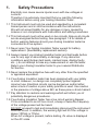
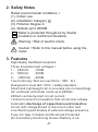
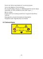
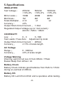
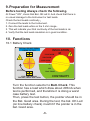
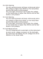
Instruction Manual
Model 307A Analog Insulation & Continuity Meter
Index
Safety Precautions........................................
Safety Notes.................................................
Features ......................................................
Connections ................................................
Specifications ...... .......................................
Why Test is necessary .................................
Instrument Layout ........................................
Lid Instruction Label ....................................
Preparation for Measurement .....................
Functions .............................. ......................
Battery & Fuse Replacement .......................
Calibration & Servicing .................................
Cleaning & Storage.......................................
Limited One-year Warranty...........................
Service Information.......................................
Page
1
2
2-3
3
4
5
6
7
8
8-14
15
16
16
17
18
YOUR COMMENTS ARE IMPORTANT TO US
We have become a market leader in test and
measurement in recent years, due to the company's
ability to design and bring to the market innovative
instruments and devices which offer real customer
benefits. The cornerstone of this ability is the
company's focus on customer requirements
and the emphasis placed on end-user satisfaction.
We appreciate customer information and requirement
to improve or design new products.
1.
1.1
1.2
1.3
1.4
1.5
1.6
1.7
1.8
Safety Precautions
Electricity can cause severe injuries even with low voltages or
currents.
Therefore it is extremely important that you read the following
information before using your Analog Insulation Tester.
This Instrument must only be used and operated by a competent
trained person and in strict accordance with the instructions.
We will not accept liability for any damage or injury caused by
misuse or non compliance with instructions and safety procedures.
This Instrument must not be used on live circuits. Ensure all circuits
are de-energised before testing. See paragraph 1.8 for details of
built-in warning features should your Analog Insulation tester be
connected to a live system.
Never open Your Analog Insulation Tester except for battery
replacement. (See Battery replacement section).
Always inspect you Analog Insulation tester and test leads before
use for any sign of abnormality or damage. If any abnormal
conditions exist (broken test leads, cracked case, display faulty
etc...) do not attempt to take any measurement or use the tester.
Return your Analog Insulation tester to your nearest Distributor
for Service.
Never replace the protective fuse with any other than the specified
or approved equivalent.
Your Analog Insulation tester has been designed with your safety
in mind. However, no design can completely protect against
incorrect use. Electrical circuits can be dangerous and/or lethal
when a lack of caution or poor safety practice is used. Use caution
in the presence of voltage above 24V as these pose a shock hazard.
Pay attention to cautions and warnings which will inform you of
potentially dangerous procedures.
Your Analog Insulation Tester has a live circuit warning bleeper.
If it is connected to an AC live circuit, a beep of twice the frequency
of the voltage present will be heard.
DO NOT proceed to test and immediately disconnect the instrument
from the circuit. In addition, the warning light will lit if the voltage is
above 100Vdc or 70Vac.
When AC voltage is present, before testing, it's value is displayed
on the AC scale.
-1-
2. Safety Notes
Rated environmental conditions
(1). Indoor use.
(2). Installation Category .
(3). Pollution Degree 2.
(4). Altitude up to 2000M
Meter is protected throughout by double
insulation or reinforced insulation.
Warning ! Risk of electric shock.
Caution ! Refer to this manual before using the
meter.
3. Features
Ÿ High Quality Taut Band movement.
Ÿ Three Insulation test voltages
Ÿ
Ÿ
Ÿ
Ÿ
Ÿ
Ÿ
Ÿ
Ÿ
Ÿ
Ÿ
1- 250Vdc
-100MW
2- 500Vdc
-200MW
3- 1000Vdc -400MW
Two Continuity Test on Low Ohms 500W & 3W
Designed to meet IEC 1010-1 safety standard..
Small and Lightweight, all in one case (do not need bag).
AC voltmeter with linear scale up to 600Vac.
200mA continuity short circuit current.
1mA test current on Insulation Test at nominal voltage.
Automatic discharge of capacitance and inductive
circuit with charge stored in the circuit under test.
Live Warning and display of external voltage presence.
Fuse, Air Gap, Crowbar and Overload Protected.
On line battery monitoring shows if battery is ok..
-2-
Ÿ Auto null of the test leads on continuity tests.
Ÿ Very Low Battery Consumption.
Ÿ On-Load battery check (+/-205mA load for worst case)
operates on 8 dry batteries (AA, R6P type..)
Ÿ Mirror scale.
Ÿ Push and Turn locking switch for long and hand free
testing.
Ÿ Designed to meet international standards.
Ÿ Supplied with High Quality test leads.
4. Connections
!
LINE
CAT. III
MAX 600V
-3-
EARTH
5. Specifications
INSULATION
Test Voltage
250Vdc
500Vdc
1000Vdc
+10%-0% +10%-0% +10%-0%
Mirror scale
100MW
200MW
400MW
Mid Scale
1MW
2MW
4MW
Scale Multiplier
x1/2
x1
x2
Accuracy
±3%
Output Short-Circuit Current
1.3mA
Regulated Output Voltage (up to 1mA current)
263.5V / 525V / 1052V
CONTINUITY
Low W
0 - 3W
0 - 500 W
Test Leads / Fuse Zero W Adjustment by knob
Output Short-Circuit Current
205mA
Accuracy
±1.5% of scale length
AC Voltage
Range
Accuracy
0 - 600Vac
±3% of scale length
Voltage Warning
Warning Light Circuit Live lit from 90Vdc / 70Vac
Buzzer Beep from 24Vac / dc
Battery Check
Battery Check indicate good batteries from 8Vdc to 13Vdc
during a Load test of 205mA.
Battery OK
Battery OK Led lit from 8Vdc and is operative while testing.
-4-
6. Why test is necessary ?
INSULATION
Every electrical apparatus and installation need to be safe
for the user and for the equipment itself.
Electrical conductors of electricity need to be insulated
from each other, so that they do not create electrical
hazard or unnecessary consumption.
Badly insulated circuits can create leakage current which
can be dangerous and trip your GFCI, RCCB or ELCB..
Each country regulate those levels at which the insulation
is acceptable.
Generally, Insulation resistance measurements are done
between each conductor and the earth, and between
each conductors.
CONTINUITY
Checking the continuity of wires, complete circuits,
connections, closure of contacts, circuit breakers, fuses,
bounding resistance of connections, etc... Are all very
important.
-5-
7. Instrument Layout
4
3
5
N-E
P-E
!
FOR Vac: DO NOT PRESS
PRESS TO TEST
INSULATION
MW
1000V/400MW
!
500V/200MW
250V/100MW
3W
500W
LOCK
1
Batt. Check
W
CONTINUITY
FOR CONTINUOUS
TESTING, PRESS AND TURN
ALWAYS ENSURE CIRCUIT TO TEST
IS FREE OF VOLTAGE BEFORE
PROCEEDING WITH CONTINUITY
OR INSULATION TESTING.
CATIII 600V
0W
ZERO
OHM
ADJUST
INSULATION-CONTINUITY METER
1. Test Button Switch.
2. Function Selector
3. Battery OK indicator
4. Mirror Scale
5. Live Circuit Warning Light
6. Test Leads and Fuse Zeroing Knob
-6-
2
6
INSTRUCTIONS ANALOG INSULATION-CONTINUITY TESTER
-7-
CONTINUITY TESTS - W Ranges
1. Select the desired ohm range, 3W or 500W.
2. Short the test leads, press test button and
adjust the ohms zero ADJ to zero the pointer
on the 0W (green scale)
3. Check the circuit is not LIVE.
4. Connect the test leads to the circuit under test.
Press the test button. Read the selected range
directly.
GENERAL:
Ÿ For AC Voltmeter, do not press test button, this is the default mode of the instrument.
Ÿ AC Voltmeter can works without batteries.
Ÿ Insulation or Continuity mode: for continous operation, press and turn the test button.
SAFETY PRECAUTION !
Ÿ The circuit must not be LIVE, conduct initial checks first. If at any time , the "LIVE"circuit light is lit,
or the warning buzzer sounds - DO NOT PROCEED, the circuit is live.
Ÿ Using the instrument in Insulation Mode may leave the circuits charged up if test leads are removed
too quickly. Avoid this by releasing the test button while the test leads are still connected to the
circuit for a few seconds.
INSULATION TESTS MW Ranges
1. Select the desired insulation test voltage
range, 250V, 500V, or 1000V.
2. Connect the leads to the instrument and circuit
under test.
3. Check the circuit is not LIVE.
4. Press the test button. Read the red MW scale
directly for 500V, multiply by 0.5 (or divide by 2)
for 250V and multiply by 2 for 1000V.
WARNING: This instrument must only be used by a competent trained individual. Consult the full
operating instructions. Never press the test button before connecting test leads to circuit to test.
INITIAL CHECKS:
1. Switch to "Batt. Check" and depress the test button. If the pointer does not move to "BATT. GOOD",
the battery needs to be replaced before proceeding.
2. Connect test leads to instrument, switch to 3W. Press and turn the test button (continuous mode),
short the test leads. The pointer should swing from infinite towards zero.
8. Lid Instruction Label
9.Preparation for Measurement
Before testing Always check the following.
At Power "ON", check that Bat. OK led lit. And check that there is
no visual damage to the Instrument or test leads.
Check the test Leads continuity
1. Connect the leads to the Instrument.
2. Zero the test leads while on the 3 ohm range..
3. This will indicate your that continuity of the test leads is ok.
4. Verify that the test leads insulation is in good condition.
10. Functions
10.1 Battery Check
FOR Vac: DO NOT PRESS
PRESS TO TEST
!
INSULATION
MW
1000V/400MW
500V/200MW
250V/100MW
3W
N-E
LOCK
!
500W
P-E
Batt. Check
W
CONTINUITY
FOR CONTINUOUS
TESTING, PRESS AND TURN
Turn the function selector to Batt. Check. This
function has a load which draw about 205mA when
test is performed, and therefore it is doing a worst
case battery test.
Then, press the test button, the pointer should be in
the Bat. Good area. During the test, the bat. OK Led
(on line battery check) must lit if the pointer is in the
bat. Good area.
-8-
10.2 DC Warning
The DC warning buzzer will beep continuously when
DC voltage is higher than 30Vdc on the test probes
and the test button is Not pressed.
The neon light "circuit live" will lit when the voltage
on the test probes is higher than 90Vdc and the test
button is not pressed.
10.3 AC Warning
The AC warning buzzer will beep continuously when
AC voltage is higher than 20Vac on the test probes
and the test button is Not pressed.
The neon light "circuit live" will lit when the voltage
on the test probes is higher than 65Vdc and the test
button is not pressed.
10.4 AC Measurement
The AC measurement is automatic on this instrument.
as soon as AC voltage is present on the test leads,
the instrument will display the AC voltage from 20 to
600Vac on the linear scale.
-9-
10.5 Low ohms measurement 0 - 500W
FOR Vac: DO NOT PRESS
PRESS TO TEST
!
INSULATION
MW
1000V/400MW
500V/200MW
250V/100MW
3W
N-E
LOCK
!
500W
P-E
Batt. Check
W
CONTINUITY
FOR CONTINUOUS
TESTING, PRESS AND TURN
Always check for voltage before testing and
measuring on a circuit. This instrument is intended
for measuring Low W and Insulation resistance on
un-energized circuits only.
Use the procedure explained at points 7.2, 7.3, 7.4.
The first procedure to follow, is to zero the test leads
and the fuse resistance.
The instrument is equipped with a Zero W Knob.
First, short circuit the test leads by connecting them
together, then, press the test button and adjust the
zero W knob until the pointer is precisely on the "0" of
the 500W scale. Use the mirror scale to be precise
With the pointer.
Connect the test leads to the circuit
0W
to be measured.
ZERO
OHM
For short test, press button and keep
ADJUST
pressed.
For long test or hand free Measurements, press and
turn the test button.
-10-
10.6 Low ohms measurement 0 - 3W
FOR Vac: DO NOT PRESS
PRESS TO TEST
!
INSULATION
MW
1000V/400MW
500V/200MW
250V/100MW
3W
N-E
LOCK
!
FOR CONTINUOUS
TESTING, PRESS AND TURN
500W
P-E
Batt. Check
W
CONTINUITY
Always check for voltage before testing and
measuring on a circuit. This instrument is intended
for measuring Low W and Insulation resistance on
un-energized circuits only.
Use the procedure explained at points 7.2, 7.3, 7.4.
The first procedure to follow, is to zero the test leads
and the fuse resistance.
The instrument is equipped with a Zero W Knob.
First, short circuit the test leads by connecting them
together, then, press the test button and adjust the
Zero W knob until the pointer is precisely on the "0"
of the 3W scale. Use the mirror scale to be precise
with the pointer.
Connect the test leads to the circuit
0W
to be measured.
ZERO
OHM
For short test, press button and keep
ADJUST
pressed.
For long test or hand free Measurements, press and
turn the test button.
-11-
10.7 Insulation Resistance Measurement @ 250Vdc
FOR Vac: DO NOT PRESS
PRESS TO TEST
!
INSULATION
MW
1000V/400MW
500V/200MW
250V/100MW
3W
N-E
LOCK
!
500W
P-E
Batt. Check
W
CONTINUITY
FOR CONTINUOUS
TESTING, PRESS AND TURN
Always check for voltage before testing and
measuring on a circuit. This instrument is intended
for measuring Low W and Insulation resistance on
un-energized circuits only.
Use the procedure explained at points 7.2, 7.3, 7.4.
Check the test leads and fuse resistance byzeroing
the test leads and fuse as per the 7.6 procedure.
Connect the test leads to the circuit to be measured
and wait for a few seconds. The instrument will
automatically discharge any remaining energy which
could be present on the circuit, and will check for
voltage at the same time.
Once you are sure that the circuit to be tested is not
Energized, then press the button for a short test
duration or press and turn the button for a long test.
Once you end the test, allow a few seconds for the
Instrument to automatically discharge the circuit.
-12-
10.8 Insulation Resistance Measurement @ 500Vdc
FOR Vac: DO NOT PRESS
PRESS TO TEST
!
INSULATION
MW
1000V/400MW
500V/200MW
250V/100MW
3W
N-E
LOCK
!
500W
P-E
Batt. Check
W
CONTINUITY
FOR CONTINUOUS
TESTING, PRESS AND TURN
Always check for voltage before testing and
measuring on a circuit. This instrument is intended
for measuring Low W and Insulation resistance on
un-energized circuits only.
Use the procedure explained at points 7.2, 7.3, 7.4.
Check the test leads and fuse resistance byzeroing
the test leads and fuse as per the 7.6 procedure.
Connect the test leads to the circuit to be measured
and wait for a few seconds. The instrument will
automatically discharge any remaining energy which
could be present on the circuit, and will check for
voltage at the same time.
Once you are sure that the circuit to be tested is not
energized, then press the button for a short test
duration or press and turn the button for a long test.
Once you end the test, allow a few seconds for the
Instrument to automatically discharge the circuit.
-13-
10.9 Insulation Resistance Measurement @ 1000Vdc
FOR Vac: DO NOT PRESS
PRESS TO TEST
!
INSULATION
MW
1000V/400MW
500V/200MW
250V/100MW
3W
N-E
LOCK
!
500W
P-E
Batt. Check
W
CONTINUITY
FOR CONTINUOUS
TESTING, PRESS AND TURN
Always check for voltage before testing and
measuring on a circuit. This instrument is intended
for measuring Low W and Insulation resistance on
un-energized circuits only.
Use the procedure explained at points 7.2, 7.3, 7.4.
Check the test leads and fuse resistance byzeroing
the test leads and fuse as per the 7.6 procedure.
Connect the test leads to the circuit to be measured
and wait for a few seconds. The instrument will
automatically discharge any remaining energy
which could be present on the circuit, and will check
for voltage at the same time.
Once you are sure that the circuit to be tested is not
energized, then press the button for a short test
duration or press and turn the button for a long test.
Once you end the test, allow a few seconds for the
instrument to automatically discharge the circuit.
-14-
11. Battery & Fuse Replacement
11.1 Battery Replacement
Your Analog insulation tester's battery is situated
under the tester. The Bat. OK will not lit when battery
need to be replaced.
Disconnect the test leads from the Instrument,
remove the battery cover and the batteries.
Replace with eight 1.5V R6 or L6 batteries, taking
care to observe the correct polarity.
Replace battery and the battery cover.
11.2 Fuse replacement
The Fuse is located next to the Batteries.
To replace Fuse, proceed as per Battery
replacement to open the battery cover, then remove
and replace the fuse located under the battery
holder. Only replace with same specification fuse.
(0.5A)
-15-
12. Calibration & Servicing
Contact your nearest distributor about Calibration
Certificate and Servicing .
Before returning the Instrument, ensure that :
Ÿ the leads have been checked for continuity and
signs of damage.
Ÿ The batteries are in good condition.
13. Cleaning & Storage
Periodically wipe the case with a damp cloth and
detergent; do not use abrasives or solvents.
If the meter is not to be used for long periods or
longer than 60 days, remove the batteries and store
them separately.
Warning
To avoid electrical shock or damage to the meter,
do not get water inside the case.
-16-
14. Limited One-year Warranty
B&K Precision warrants to the original purchaser that its
products and the component parts thereof, will be free from
defects in workmanship and materials for a period of one
year from date of purchase from an authorized B&K
Precision distributor.
B&K Precision will, without charge, repair or replace, at its
option, defective product or component parts. Returned
product must be accompanied by proof of the purchase
date in the form of a sales receipt.
To obtain warranty coverage in the U.S.A., this product
must be registered by completing the warranty registration
form on www.bkprecision.com within fifteen (15) days of
purchase.
Exclusions: This warranty does not apply in the event
of misuse or abuse of the product or as a result of
unauthorized alterations or repairs. The warranty is
void if the serial number is altered, defaced or removed.
B&K Precision shall not be liable for any consequential
damages, including without limitation damages resulting
from loss of use. Some states do not allow limitations of
incidental or consequential damages. So the above
limitation or exclusion may not apply to you.
This warranty gives you specific rights and you may have
other rights, which vary from state-to-state.
B&K Precision
22820 Savi Ranch Parkway
Yorba Linda, CA 92887
www.bkprecision.com
714-921-9095
-17-
15. Service Information
Warranty Service: Please return the product in the
original packaging with proof of purchase to the address
below. Clearly state in writing the performance problem
and return any leads, probes, connectors and
accessories that you are using with the device.
Non-Warranty Service: Return the product in the
original packaging to the address below. Clearly state in
writing the performance problem and return any leads,
probes, connectors and accessories that you are using
with the device. Customers not on open account must
include payment in the form of a money order or credit
card. For the most current repair charges please visit
www.bkprecision.com and click on "service/repair".
Return all merchandise to B&K Precision with pre-paid
shipping. The flat-rate repair charge for Non-Warranty
Service does not include return shipping. Return
shipping to locations in North American is included for
Warranty Service only. For overnight shipments and
non-North American shipping fees please contact B&K
Precision.
B&K Precision
22820 Savi Ranch Parkway
Yorba Linda, CA 92887
www.bkprecision.com
714-921-9095
Include with the returned instrument your complete
return shipping address, contact name, phone
number and description of problem.
-18-
B&K Precision
22820 Savi Ranch Parkway
Yorba Linda, CA 92887
U.S.A.
www.bkprecision.com
Printed in Taiwan / Ver. 1.0/0307
© 2007 B&K Precision Corporation