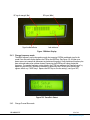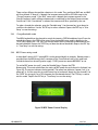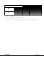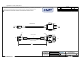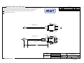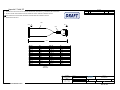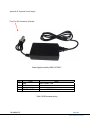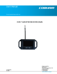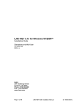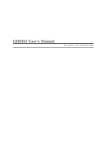
1
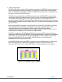
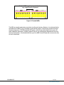
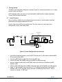
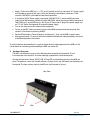
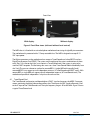
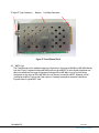
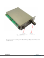
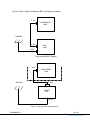
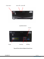
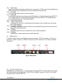
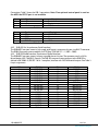
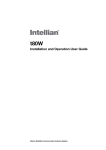
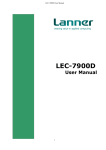
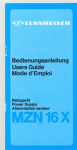
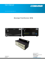
User’s Manual The most important thing we build is trust. Messenger Smart Receiver (MSR) 100-M0061X5C 05/22/09 Cobham Surveillance GMS Products 1916 Palomar Oaks Way Ste 100 Carlsbad, CA 92008 T: 760-496-0055 F: 760-496-0057 www.cobham.com/gms TABLE OF CONTENTS 1 INTRODUCTION ....................................................................................................................................................................... 5 1.1 Key System Features ............................................................................................................................................................. 5 2 THEORY OF OPERATION .................................................................................................................................................... 6 3 GETTING STARTED ................................................................................................................................................................ 8 3.1 Initial Checkout........................................................................................................................................................................ 8 4 HARDWARE OVERVIEW ...................................................................................................................................................... 9 4.1 Tuner/Demod Card.............................................................................................................................................................. 10 4.2 BDCC Card ............................................................................................................................................................................... 11 4.2.1 Power Switch .................................................................................................................................................................... 15 4.2.2 Active LED .......................................................................................................................................................................... 15 4.2.3 Locked LED......................................................................................................................................................................... 15 4.2.4 Control Panel (Optional) .............................................................................................................................................. 15 4.2.4.1 Display (Alpha-Numeric) .................................................................................................................................. 15 4.2.4.2 Arrow Keys (Up/Down) ..................................................................................................................................... 15 4.2.4.3 CTRL key ................................................................................................................................................................... 15 4.2.4.4 ENTR Key ................................................................................................................................................................. 15 4.3 MSR Rear Panel ..................................................................................................................................................................... 15 4.3.1 RS-232C and USB-1 Port ............................................................................................................................................ 15 4.3.2 DVB ASI Out (Asynchronous Serial Interface) ................................................................................................. 16 4.3.3 DVB SPI Parallel Interface (Synchronous Parallel Interface) ..................................................................... 16 4.3.4 DC Power ............................................................................................................................................................................ 17 5 SOFTWARE OVERVIEW........................................................................................................................................................... 17 5.1 System Requirements ........................................................................................................................................................ 18 5.2 Software Installation .......................................................................................................................................................... 18 5.3 Software Functions ............................................................................................................................................................. 19 5.3.1 Function Buttons and Selects ................................................................................................................................... 19 5.3.2 Pull-Down Menu Definitions ..................................................................................................................................... 20 5.3.2.1 File ............................................................................................................................................................................... 20 5.3.2.2 Configuration......................................................................................................................................................... 20 5.3.2.3 Help............................................................................................................................................................................. 32 5.3.3 Field Definitions .............................................................................................................................................................. 32 5.3.3.1 “Modulation (Captured)” region ................................................................................................................... 32 5.3.3.2 “Tuners” region ..................................................................................................................................................... 33 5.4 Control Panel (Optional) ................................................................................................................................................... 33 5.4.1 Change frequency mode ............................................................................................................................................ 35 5.4.2 Change Channel Plan mode....................................................................................................................................... 35 5.4.3 Change Bandwidth mode ........................................................................................................................................... 36 5.4.4 BDCC Power settings mode ....................................................................................................................................... 36 6 SPECIFICATIONS ................................................................................................................................................................. 37 7 USER NOTICE .......................................................................................................................................................................... 38 APPENDICES....................................................................................................................................................................................... 40 100-M0061X5C 2 of 43 www.cobham.com/gms List of Figures Figure 1 Four CH MSR w/optional BDCC-s ....................................................................................................................... 6 Figure 2 Chained MSRs .................................................................................................................................................................. 7 Figure 3 System Configuration two channels................................................................................................................ 8 Figure 4 Front/Rear views (with and without local control) ............................................................................ 10 Figure 5 Tuner/Demod Card .................................................................................................................................................... 11 Figure 6 BDCC Card........................................................................................................................................................................ 12 Figure 8B Front Panel w/Optional Control Panel...................................................................................................... 14 Figure 9 Rear Panel ........................................................................................................................................................................ 15 Figure 10 User Interface (Maximum info display) .................................................................................................. 18 Figure 11 MDL Configurator .................................................................................................................................................... 19 Figure 12 Configuration Menu ............................................................................................................................................... 20 Figure 13 Display Selection ..................................................................................................................................................... 21 Figure 14 Display with C/N and BER enabled.............................................................................................................. 21 Figure 15A Channel select method .................................................................................................................................... 22 Figure 15B BAS Frequency select method.................................................................................................................... 23 Figure 15C User defined selection table ........................................................................................................................ 24 Figure 15D User Defined select method ........................................................................................................................ 25 Figure 16 Password ........................................................................................................................................................................ 26 Figure 17A Remote BDC Setup ............................................................................................................................................. 28 Figure 17B Local BDCC Setup................................................................................................................................................. 30 Figure 18 Slot Power..................................................................................................................................................................... 31 Figure 19, DDP Set up Window ............................................................................................................................................. 31 Figure 19A The operational Program Flowchart ....................................................................................................... 34 Figure 19B Main Display ............................................................................................................................................................ 35 Figure 19C Save/Exit Select..................................................................................................................................................... 35 Figure 20 BDC Power Control Display .............................................................................................................................. 36 List of Appendices Appendix A: Cable, Power, MSR ............................................................................................................................................ 40 Appendix B: Cable, Power, MSR, Pigtail ........................................................................................................................... 41 Appendix C: Cable, SPI ................................................................................................................................................................ 42 Appendix D: Optional Power Supply ................................................................................................................................. 43 100-M0061X5C 3 of 43 www.cobham.com/gms Acronyms This section lists and describes the various acronyms used in this document. Name 16 QAM 64 QAM A A/V AES ASI BDC COFDM CVBS D/C DVB-T FEC GUI I/O Kbaud Kbps LO Mbps MDL MDT MSR MER MPEG NTSC PAL QPSK RF RX S/N SPI THD TS TX VAC VDC Meaning 16-State Quadrature Amplitude Modulation 64-State Quadrature Amplitude Modulation Amperes Audio/Video Advanced Encryption System Asynchronous Serial Interface Block Down Converter Coded Orthogonal Frequency Division Multiplexing Composite Video Down-Converter Digital Video Broadcasting - Terrestrial Forward Error Correction Graphical User Interface Input/ Output Kilobaud per second Kilobits per second Local Oscillator Megabits per second Messenger Digital Link Messenger Digital Transmitter Messenger Smart Receiver Modulation Error Rate Moving Picture Experts Group National Television System Committee Phase Alternation Line Quadrature Phase Shift Keying Radio Frequency Receiver Signal-to-Noise Ratio Parallel Transport Stream Total Harmonic Distortion DVB MPEG Transport Stream Transmitter Volts (Alternating Current) Volts (Direct Current) 100-M0061X5C 4 of 43 www.cobham.com/gms 1 Introduction GMS’ Messenger Smart Receiver (MSR) System is a VHF/UHF DVB-T Receiver with several powerful and unique features. When used in conjunction with GMS’ Block Down Converters (BDC), the MSR can cover frequency bands exceeding 7 GHz. The first unique feature is Multiple-Input Maximal-Ratio Diversity Combining, up to six independent receive paths per MSR. Another feature is the MSR’s Doppler handling ability. Multiple MSRs can be linked together to form very large Diversity systems. Unlike conventional DVB-T systems, the MSR is designed for mobile environments. With 2 K carriers and 16 QAM, a dual-input or greater MSR can handle greater than 570 Hz of Doppler frequency shift, which equates to 708 mph (1140 km/h) @ 504 MHz carrier frequency. With 8 K carriers and 16 QAM, a dual-input or greater MSR can handle greater than 125 Hz of Doppler frequency shift, which equates to 155 mph (250 km/h) @ 500 MHz carrier frequency. This feature is an enabling technology for COFDM based Helicopter and UAV links. This manual provides information on how to operate the MSR as well as pertinent technical information related to the overall system. Important --- Please refer to “User Notice” for updated operational limitations. 1.1 Key System Features Robust Link Performance with COFDM Multi-Input Diversity Maximal-Ratio Combining Provide superior coverage in the toughest reception areas Enhanced Doppler performance for tracking moving vehicles ASI output supports a wide variety of external decoders 49 MHz to 7 GHz (In-Bands) with Optional Internal or External Down - Converters 100-M0061X5C 5 of 43 www.cobham.com/gms 2 Theory of Operation The MDL system utilizes a robust digital modulation system known as COFDM that provides frequency diversity and powerful Forward Error Correction (FEC) algorithms. The end result is a robust wireless link that is effective against multipath interference experienced by analog systems, and provides crisp, clear pictures in the most difficult of terrains. The MSR receives and demodulates a DVB-T signal and recovers the DVB MPEG-2 transport stream containing the digital video, audio and ancillary data. This stream can be optionally encrypted with a 128-bit Advanced Encryption System (AES) to provide protection in sensitive applications. The recovered Transport Stream (TS) is decrypted (Option sold separately) and converted to Asynchronous Serial Interface (ASI) and SPI Parallel Transport Stream (SPI). The ASI and SPI are output from the back panel of the MSR. External Audio/Video/Data Decoders are sold separately that support SD and HD MPEG-2 4:2:0 and/or 4:2:2, H.264, AVC and any other format that can be transmitted in a transport stream. LAN IP streaming interfaces are also available from GMS to support distribution of the Wireless Audio/Video/Data anywhere in the world via the Internet. This system architecture supports single or multiple programs by looping the ASI interface to multiple Decoders. The MSR is normally used with GMS’ optional Block Down-Converters (BDCs) to provide frequency coverage from 862 MHz to 6 GHz. GMS’ BDCs can be mounted remotely, normally right at the antenna output (optimizing system performance) or within the MSR chassis. When remotely mounted, BDC power can be provided via the IF coax cable. The MSR’ MS Windows Control SW provides independent control of the power to each BDC. A single MSR with internally mounted BDCs, can support up to 4 independent antennas. With external BDCs, each single MSR can support up to 6 independent antennas. The system automatically configures itself for inputs from 1 to 6 per MSR. Both even and odd configurations are supported. 4 CH MSR with optional Block Down-Converters TUNER / DEMOD BLOCK DWN CONV TUNER / DEMOD BLOCK DWN CONV TUNER / DEMOD BLOCK DWN CONV TUNER / DEMOD BLOCK DWN CONV Figure 1 Four CH MSR w/optional BDCC-s 100-M0061X5C 6 of 43 www.cobham.com/gms Multiple MSRs can be connected to form very large Diversity Systems! Figure 2 Chained MSRs The MSR can provide autonomous acquisition, tracking and recovery. However, it was designed to be controlled via an IBM PC using a Window’s-based control program. The program provides control of the center frequency, COFDM bandwidth, BDC power, and the acquisition mode of the system. All other modulation parameters, including spectral inversion, are automatically detected and set during the acquisition process. Once locked onto the signal, the MSR Control SW provides an extensive array of status information. 100-M0061X5C 7 of 43 www.cobham.com/gms 3 Getting Started The MSR is pre-configured by GMS prior to shipment (based on customer requirements), thus is ready to work “right out of the box”. NOTE: Additional cables and antennas may be delivered by GMS based on customer application. Contact GMS for further information. 3.1 Initial Checkout Prior to installing an MSR unit into the desired target environment, an initial checkout should be performed to ensure proper operation of the unit. Figure 3 shows a basic MSR system configuration. The steps necessary to setup the system configuration in Figure 3 are shown below. LOCAL BDC CABLE ASSEMBLY 780-234 RS232 VIDEO ASI REMOTE BDC Power Supply DECODER MDT VIDEO MONITOR Video Source RECEIVER/DEMOD COMPUTER POWER SUPPLY 12VDC NOM. 473-051 Figure 3 System Configuration two channels Install Omni-directional antennas onto the MDT RF output port. Install antennas on Remote BDC RF input port and local BDC. Attach the MDT breakout cable (DB-44 end) to the MDT unit. Attach a RF cable from the BDC output port to MSR IF of RX/Demod card. Attach a composite video source to MDT BNC video input cable that is located on the MDT breakout cable. Attach a video cable from one of the BNC video output ports on the Decoder to a video monitor. Apply +12 Vdc to the MDT unit using the red (+12 V) and black (ground) wires from the MDT breakout cable. NOTE: The power supply used needs to be able to provide at least 1 Amp of current at a nominal +12 VDC input. 100-M0061X5C 8 of 43 www.cobham.com/gms Apply +12Vdc to the MSR, pins 1 (+12 V) and 2 (ground) to the 2 pin connector (P1). Power supply must be able to source up to 6 amps (when also powering external down converters). Cable assembly 780-C0242 is provided to make these connections. If an optional AC/DC Power supply is purchased (GMS # 473-051), attach the XLR connector (male) to the XLR connector (female) of cable 780-C0234. Attach the two pin Molex connector of 780-C0234 to P1 of the MSR chassis. (Ref. Figure 3). Plug in the AC plug of the power supply into an 115 VAC Outlet. See Appendix D for optional power supply. Turn on the video source and video monitor equipment. To turn on the BDC (down converter) from the front MSR control panel at the computer. See section 6.3 for details on powering the BDC. Set the RF Bandwidth & Center Frequency and then push “Tune” on the MSR’s control screen. After approximately 2-5 seconds, the link should be established and video provided by the source should be displayed on the monitor. The initial checkout described above is simply to check the basic video operation of the MSR unit. For further details on monitoring and controlling the MSR, see section 6.3 4 Hardware Overview The MSR’s versatile housing can sit on a desktop or be mounted with the optional 19-inch instrumentation rack-mount kit. It can be optionally supplied with a local control panel. All interface connectors (Power, RS232, USB, ASI and SPI) are located on the rear of the MSR unit panel. The power on switch and two led indicators (System Active and ASI locked) are located on the front panel. The front and rear view of the MSR unit are illustrated in Figure 4. Rear View Slot 8 100-M0061X5C Slot 1 9 of 43 www.cobham.com/gms Front View With display Without display Figure 4 Front/Rear views (with and without local control) The MSR chassis is fitted with an active backplane motherboard consisting of eight 80-pin connectors. The motherboard is protected with a 2.5 amp resettable fuse. The MSR is designed to accept 9-15 VDC input power. The 80 pin connectors on the motherboard can accept a Tuner/Demod card, a local BDCC card or a Digital Data Processor Card (DDPC). The system can be configured for various combinations of these cards. Slot 1 (first slot on the right), must contain a Tuner/Demod card if the system is going to be used for DVB-T reception. The remaining slots must use a slave Tuner/Demod filled incrementally from slot 2 to 6.The user can choose to use local or remote BDCs. A single MSR with internally (local) mounted BDCCs can support up to 4 independent antennas (4 Tuner/Demod and 4 BDCC cards). With remote BDCs, a single MSR can support up to 6 independent antennas (6 Tuner/Demod cards). The motherboard provides 8 independent 1 amp fuses to each card slot. 4.1 Tuner/Demod Card The Tuner/Demod card receives and demodulates a DVB-T signal and recovers the MPEG-2 transport stream containing the digital video audio ancillary data. The output of a BDC (Local or Remote) is fed to the IF input of the Tuner/Demod card. The input frequency range is 49 to 862 MHz. Figure 5 shows a typical Tuner/Demod card. 100-M0061X5C 10 of 43 www.cobham.com/gms IF Input (F Type Connector) Bottom Card Edge Connector Figure 5 Tuner/Demod Card 4.2 BDCC Card The Tuner/Demod card is capable of receiving frequencies in the range of 49 MHz to 862 MHz directly into the IF input. Frequencies above 862 MHz make use of the BDCC in which higher frequencies are down converted into the range of frequencies between 49 to 862 MHz. In cases in which direct frequencies in the range of 49 to 862 MHz are used, there is no need for a BDCC. However an LNA (Low Noise Amplifier) can be used if the antenna is remotely mounted to overcome cable losses. Figure 6 shows a typical BDCC card. 100-M0061X5C 11 of 43 www.cobham.com/gms RF Input SMA Connector IF Output F Type connector Figure 6 BDCC Card The antenna is attached to the RF input of the BDC. The IF Output (BDC) is fed to the IF input of the Tuner/Demod card. 100-M0061X5C 12 of 43 www.cobham.com/gms Figure 7 shows a typical Tuner/Demod, BDC, and antenna connection. IF IN TUNER/DEMOD CARD ANTENNA IF OUT BDCC CARD RF IN Tuner and Local BDCC diagram IF IN TUNER/DEMOD CARD ANTENNA IF OUT REMOTE BDC RF IN Figure 7 Tuner/Demod and BDC diagrams 100-M0061X5C 13 of 43 www.cobham.com/gms Power Switch Active LED Locked LED Figure 8A Front Panel CTRL Key Display Arrow keys ENTR Key Figure 8B Front Panel w/Optional Control Panel 100-M0061X5C 14 of 43 www.cobham.com/gms 4.2.1 Power Switch Depressing the Power On toggle switch will cause system power (12 VDC nominal) to be applied to the MSR unit. Depressing the switch again will cause system power to be removed. 4.2.2 Active LED The Active LED indicates that the system has power. 4.2.3 Locked LED The Locked LED indicates that at least one of the Demodulators is locked and outputting an MPEG TS if it is available. Note: A lit; Locked LED indicator does not guarantee that the TS is completely error free. A blinking LED indicates a non-locked condition. 4.2.4 Control Panel (Optional) 4.2.4.1 Display (Alpha-Numeric) The display gives the user a visual indication of the reception status and allows the user to enter data for key parameters. 4.2.4.2 Arrow Keys (Up/Down) The up/down arrow keys are used to increment (up) or decrement (down) data entry values to be entered for a specific parameter. 4.2.4.3 CTRL key The CTRL key allows the user to scroll thru the various modes of operation. 4.2.4.4 ENTR Key The ENTR key is used to enter data for a specific parameter. 4.3 MSR Rear Panel Located on the rear panel, are the following interface connectors: a “SPI Out” connector, a “Diversity In” connector, a “USB-1” connector, a “RS232C” connector, two “ASI” connectors, and a “Power” connector. See Figure 9. USB-1 RS232C ASI Out SPI Power Figure 9 Rear Panel 4.3.1 RS-232C and USB-1 Port Full MSR System control and status is accessed through either the RS-232C or USB-1 control ports via the MS Windows based control application. The RS-232C uses a DB9-F connector. The USB-1 uses a USB-B connector. Table 1 shows the RS-232C 100-M0061X5C 15 of 43 www.cobham.com/gms Connections. Table 2 shows the USB-1 connections. Note: If an optional control panel is used on the MSR, the RS232 port is not available. Pin 2 3 5 Signal Tx Rx Gnd Description Transmit Receive GND Connection Table 1 Pin 1 2 3 4 Signal 5V USBDM USBDP USB GND Description 5V POWER DD+ GND Table 2 4.3.2 DVB ASI Out (Asynchronous Serial Interface) The DVB MPEG transport stream in high-speed serial format is output on this port via a BNC-F connector. The DVB ASI transport stream conforms to ETSI Spec TR101891 V1.1.1 (2001 – 2002). 4.3.3 DVB SPI Parallel Interface (Synchronous Parallel Interface) The DVB MPEG transport stream is output as parallel data at this port. The connector used is a 34 Pin Micro-Header, ASP-114859-01, Samtec. The DVB SPI transport stream conforms to the DVB-SPI as defined in EN 50083-9 (ISO/IEC 13818-1 compliant) interface with LVDS differential outputs. See Table 3 for pin assignments. PIN 1 2 3 4 5 6 7 8 9 10 11 12 13 14 15 16 17 100-M0061X5C SIGNAL MP DATA0+ MP DATA0MP DATA1+ MP DATA1MP DATA2+ MP DATA2MP DATA3+ MP DATA3MP DATA4+ MP DATA4MP CLK+ MP CLKMP FRM+ MP FRMMP STR+ MP STRCLKOUT+ Table 3 PIN 18 19 20 21 22 23 24 25 26 27 28 29 30 31 32 33 34 SGNAL CLKOUT GND I2C0 I2C1 DEV4 GND DIF LIN 1 MP DATA5+ MP DATA5MP DATA6+ MP DATA6MP DATA7+ MP DATA7MP LOCK+ MP LOCKMP FAIL+ MP FAIL- 16 of 43 www.cobham.com/gms 4.3.4 DC Power A 2-pin connector is used to provide an interface for the DC power input. The pin assignments for this connector are shown in Table 4. For further equipment protection, reverse polarity circuitry has been implemented internal to the MSR. The MSR can draw approximately 5.75 Amps max if fully loaded and driving eight BDCs. Pin 1 2 5 Signal POWER 9-15VDC GND Description Nominal +12VDC, 1 to 5.75 amp draw max GND Connection Table 4 Software Overview Configuration, control and monitoring of the MSR unit can be implemented by using the Windows based control program. This program provides control of the center frequency, COFDM bandwidth, power for remote BDCs and the acquisition mode of the system. All other modulation parameters are automatically detected and set during the acquisition process. Once locked onto the signal, the MSR Control software provides an extensive array of status information as shown in Figure 10. 100-M0061X5C 17 of 43 www.cobham.com/gms Figure 10 User Interface (Maximum info display) Note: The display can be adjusted from a very simple screen up to the most complex Screen as shown in Figure 10 (See section 6.3.2.2) 5.1 System Requirements The MSR Control program has been developed and tested on Microsoft Windows 2000 and Windows XP. 5.2 Software Installation The following instructions outline the installation process for MSR Control program: 100-M0061X5C 18 of 43 www.cobham.com/gms Insert provided CD-ROM into computer CD reader. Run ‘setup.exe’ file. This will launch the GMS_MSR setup program and several initial setup files will begin to be copied into the computer. After the initial setup files are copied, the GMS_MSR setup program will prompt the user to close any applications that are running. Once all other programs are exited, click on the ‘OK’ button. The GMS_MSR setup program will prompt the user to click on the ‘computer icon’ button to begin installation. If desired, the user can change the destination directory from the default. Click on the ‘computer icon’ button. The GMS_MSR setup program will then prompt the user to ‘Choose Program Group’. If desired, the user can change the program group from the default. Click on the ‘Continue’ button. After installing the MSR program, the setup program will display a window indicating the setup was completed successfully. Click ‘OK’. 5.3 To load USB Drivers see “Loading USB Drivers for MSR” on CD-ROM. Software Functions The MSR control software provides the user access to many different configuration, control and monitoring options. When the program is launched, the screen shown in Figure 11 is displayed. The user should first select the serial port the computer is connected to via the Serial Port Selector and Status region. If the selected serial port is valid, the gray-colored status box will show ‘Ready’. The Device Selector region allows the end user to select the MSR unit. To configure the MSR, select the ‘MSR’ box in the Device Selector region. Once the ‘MSR” box is selected the screen shown in Figure 8 is displayed. The MSR Control program contains function buttons and all the configurable settings available on a MSR. The following sections explain the various functions. Figure 11 MDL Configurator 5.3.1 Function Buttons and Selects Reset System Button: Clicking on this button re-initializes all tuners to a known state. Bandwidth Select Option: The system bandwidth can be selected in this field. The selections are 6,7 or 8 MHz bandwidth. 100-M0061X5C 19 of 43 www.cobham.com/gms Frequency Option: The system receive frequency is set in this field. The units are displayed in MHz. Tuning resolution is 10 KHz per step. Tune Button: Clicking on this button initiates the acquisition process. In this mode all modulation parameters are automatically detected and set during this process. The parameters which are captured are displayed in the “Modulation (Captured) region. 5.3.2 Pull-Down Menu Definitions There are pull-down menus that are included in the MSR Control program. The following section describes these menus in detail. Refer to Figure 12. Figure 12 Configuration Menu 5.3.2.1 File This pull-down menu is used solely to exit the MSR Control program. Alternatively, the ‘X’ box in the upper right hand corner of the window can be used to exit the program. 5.3.2.2 Configuration This pull-down menu contains five configuration options as outlined below: Select Display: This selection allows the user to configure the main display (See Figure 13). By applying a check to the desired feature the main display will show the selection. For example, if the user wants to only display the “C/N” and the “BER” then the “C/N Indicator” and the “BER Indicator” would be checked. See Figure 14. 100-M0061X5C 20 of 43 www.cobham.com/gms Figure 13 Display Selection Figure 14 Display with C/N and BER enabled 100-M0061X5C 21 of 43 www.cobham.com/gms Channel Select: This selection allows the user to choose the desired frequency input method. There are four basic methods: Manual, BAS New ,BAS Old, and “User Defined”. The selection pulls up a menu as shown in figure 15A. Using the manual method, the user can enter the desired center frequency manually at the main screen. Using the BAS method, pre-determined frequencies as established by the Federal Communication Commission, for the broadcast auxiliary services band, are used for the center frequency input. Using the “User Defined” method, user-defined frequencies are used for center frequency input. Figure 15A Channel select method If “Manual” is selected from the “Channels” pull down menu, the main screen as shown in figure 10 will be displayed The “User Selected” selection from the “Channels” menu, displays a screen which allows the user to input user defined frequencies (see figure 15C). Up to 30 different frequencies can be stored. When defined frequencies have been entered, click the “Save Changes” button to store settings. Figure 15D shows the main screen when the “User Selected” method is used. The pull down menu (User Channels) on the main screen is used to select the desired frequency. After the selection is made then the system can be tuned to the selected frequency by clicking on the “Tune” button of the main screen. Figure 15B shows the main screen when the “BAS Old” or “BAS New” is selected from the “Channels” menu. The pull down menu (BAS new/old Channels) on the main screen is used to select the desired frequency. After the selection is made then the system can be tuned to the selected frequency by clicking on the “Tune” button of the main screen. The “BAS New” selection is the latest defined frequencies as established by the Federal Communications Commission 100-M0061X5C 22 of 43 www.cobham.com/gms Figure 15B BAS Frequency select method 100-M0061X5C 23 of 43 www.cobham.com/gms Figure 15C User defined selection table 100-M0061X5C 24 of 43 www.cobham.com/gms Figure 15D User Defined select method 100-M0061X5C 25 of 43 www.cobham.com/gms Tuner-BDC: This selection pulls up a password window as shown in Figure 16. Upon initial installation of the MSR unit, the user will be asked to enter a password twice. This is now the password for the system. The user has the ability to change the password as discussed later in this section. After the correct password is entered a window as shown in Figure 17A or 17B is pulled up. Each slot of the MSR, except slot number one, can be configured to accept a Tuner/Demod card or a BDCC card (Local block down converter). Slot number one must be a Tuner/Demod card. The Tuner/Demod card can accept IF input from a Remote BDC or Local BDCC. The “Tuner Configuration” menu allows the user to setup various parameters based on system requirements. Figure 16 Password The MSR (and many other digital receivers) are capable of receiving direct frequencies in the range of approximately 49MHz to 861MHz. If the transmitter is not in this range, then a down-converter (BDC/BDCC) is used to convert the frequency to this range. The frequency out of the down-converter is called the IF (intermediate frequency) which is fed to a Tuner/Demod card installed in a MSR. Down-converters have an LO (local oscillator) which is mixed with the DBV-T transmitter frequency and converts it to the IF frequency. The MSR locks on to the IF frequency. The MSR must know the LO of the BDC and the frequency of the DVB-T transmitter to calculate for the correct IF frequency to tune to. This is the value that must be entered in the “Set BDC LO Frequency” field. (See Figures 17A & 17B). 100-M0061X5C 26 of 43 www.cobham.com/gms The following equation will determine the IF frequency: “Transmitter frequency - LO = IF frequency”. For example, if the transmitter is set for 2000 MHz and the LO of the down-converter is 2800 MHz, then the difference (IF frequency) is 800 MHz. Each time the transmitter frequency is changed, the MSR must be re-tuned to make corrections for the correct IF frequency. It should be noted that the equation can produce negative or positive answers. The negative answer may indicate the receiver wants the signal to be inverted. See section 6.3.3.2 of the MDT-B user manual (100-M0056) for inverting the signal. Reference the GMS web site for BDC details under “RF modules/blockdown converters” at http://www.cobham.com/gms Remote BDC Configuration Window (See Figure 17A) (The “BDC Type” must be set to “remote” in this mode) “Select Tuner”: Each tuner used in the MSR system must be configured. The “Tuner Select” is used to choose the tuner to be configured. This pull down menu has a selection from 1 thru 6 corresponding to tuner cards. “Set BDC LO”: The LO frequency of the BDC is entered in this field. The units are in MHz. All BDC-s have 1 MHz steps for LO frequency, except BDCF-s (0.01 MHz steps). “Tuner Slot Location”: Slot number one of the MSR is always configured with a Tuner/Demod card provided that the housing is being used for reception (Note: The MSR housing can be used as a housing for tuner/demods that are connected to a second housing that is performing the reception. In this case slot one can be used). Therefore, normally “Tuner Slot Location” will be set to “1” from the pull down selection. If, for example, physical slot number two is configured with a BDCC card installed then the next available slot for a tuner would be number three. In this case Tuner/Demod card number two would be configured for “Tuner slot location” number “3”. In effect a BDCC card eliminates a physical MSR slot. “Gain from Ant to Tuner”: Allows the user to specify the gain from the BDC input to the MSR input. If a long cable is used to connect the BDC to the MSR or a power splitter is used, the overall gain will be reduced. A typical BDC has a gain of 30 dBm. If the cable loss at the operating frequency was 5dB, for example, then the effective BDC Gain would be 25 dBm. “BDC Type”: The type is selected from this pull down menu. The choices are “None”, “Local” and “Remote”. If a BDCC is installed in a specified slot then the selection would be “None”. “BDC Power”: Remote BDCs can be powered locally or remotely. Remote power is provided from the MSR through the F connector of the Tuner/Demod card. Clicking the “BDC Power button” to “On’ will supply +12 VDC through the coax cable to the BDC. Power can be turned on or off independently for each channel. If the BDC is located relatively close to the MSR unit then using remote power makes sense. However, if the BDC is located at a great distance away from the MSR, there may be excessive DC drop in the 100-M0061X5C 27 of 43 www.cobham.com/gms coax cable (due to cable resistance). If this is the case, then local DC power should be considered. If unsure of the DC voltage drop, then measure the DC voltage present (using a DMM) at the end of the coax cable run. The DC normal operating voltage is approximately +12 VDC but can operate down to +10 VDC. Local power is provided by applying +12 VDC to pin 1, GND to pin 3 of the DB-9 connector located on the bottom of the BDC. The +12 Volt power must be able to source at least 500ma. The power switch (located on the side of the BDC) enables the user to control the ‘ON’/’OFF’ positions for local power. NOTE: If using local power, the remote power should be turned ‘OFF’ using the BDC Power On/Off button. Not doing so could cause damage to the tuner Figure 17A Remote BDC Setup Local BDCC Configuration Window (See Figure 17B) (The “BDC Type” must be set to “Local” in this mode) The following functions have been previously defined in the Remote BDC section: “Select Tuner”, “Set BDC LO”, “Tuner slot location”, “BDC Type”, “Gain from Ant to Tuner” and “BDC Power”. Note: BDCC cards are powered remotely only (From MSR) 100-M0061X5C 28 of 43 www.cobham.com/gms “BDCC Address”: Each locally mounted BDCC is assigned a unique address. If a tuner is to operate with a specific BDCC then the tuner must be set to match the address of the BDCC. The address will be labeled on the BDCC chassis. “IF Attenuation”: A BDCC has a typical maximum gain of 39 dBm. The gain of the BDCC can be attenuated with this setting. The value can be changed in increments of 1dB. BDCCs are typically shipped with the gain adjusted to 30 dBm (+/- 2 dBm) with an IF attenuation set between 9 and 11 dBm. This attenuation can be reduced if you need to drive long cable runs. “RF AGC Mode”: The two selections from this pull down menu are “Auto” and “Manual”. In normal operation the AGC (Automatic Gain Control) is set to “Auto In the “Auto” mode, RF attenuation is automatically adjusted based on the strength of the RF Input signal or signals going in to the BDCC. By selecting the “Manual” mode, the “Auto” mode is disabled and the RF gain of the BDCC is fixed at approximately 20 dBm. NOTE: Caution must be taken when operating in the “Auto mode”. If multiple Transmitters are operating within the band of the system and an unwanted frequency has a higher power at the antenna than the tuned frequency, then the overall performance of the BDCC could be affected. The unwanted frequency could cause the AGC to decrease the gain of the BDCC thereby decreasing the signal to noise ratio and increasing the noise figure. If the desired transmitter is a long distance away from the receiver antenna, reception problems may occur. If this condition should occur the “Manual mode” would be recommended. “RF Attenuation”: This display allows the user to monitor the level of the RF attenuation of the BDCC. This function is available when the BDCC RF AGC mode is in “Auto”. If in the “Manual mode” the RF attenuation will always be zero. “LO Frequency”: The LO frequency of the BDCC is displayed in this field. “Poll On”: This selection provides the user with the status of the RF attenuation level (dB). This is typically used or turned on when the BDCC is switched to “Auto” RF attenuation mode. . This setting defaults to “Poll ON” when in the “Auto” mode and “Poll Off” when “Manual” mode is selected. The “Poll On/Off” can be toggled on or off manually. 100-M0061X5C 29 of 43 www.cobham.com/gms Figure 17B Local BDCC Setup “Query”: This selection is used to query the system for the latest settings for the selected tuner. “Apply Button”: This selection is used to apply all changeable parameters of the system. “Close”: Exit the tuner configuration “Reset Password”: This selection allows the user to change the password. The user will be asked to enter the new password twice to confirm input. The password is case sensitive. After clicking this button the user will be asked to re-enter a new password upon re-entry to the Tuner-BDC configuration “Save Configuration”: Once the previous steps have been completed, “Save Configuration” to ensure all selections have been properly saved. Slot Power Remote or local BDCs/BDCCs are normally powered thru a Tuner/Demod card. Remote power is provided from the MSR through the “F” connector of the Tuner/Demod card. Clicking one of the “Slot Power” buttons” to “On’ will supply +12VDC through the coax cable to the BDC/BDCC. See Figure 18. Position “1” corresponds to Tuner/Demod card 1, position “2” corresponds to Tuner/Demod card “2”, etc. If a BDCC is configured to reside in one of the slots then it would be invalid to turn on the “Slot Power” in which the BDCC resides. 100-M0061X5C 30 of 43 www.cobham.com/gms Figure 18 Slot Power DDP Set up This selection opens up a window where user can control various features, depending on the system configuration. If the system has Encryption, High Speed Data and User Data capabilities, then the window will look like one in Figure 19. Figure 19, DDP Set up Window 100-M0061X5C 31 of 43 www.cobham.com/gms AES, NEVER Store the key in the DDP mode: This mode does AES Decryption but the Decryption key must be reloaded every time it is powered off. This is for higher security. AES, Store the key in DDP mode: This mode does AES Decryption and the DDPC remembers the Decryption key so when the DDPC is powered on it will come up working. Descrambling key: This box loads the decryption key. The Descrambling mode must be set to an AES mode before this input is available. User Data enables User Data capabilities. High Speed Data enables MSR to receive High Speed Data. “Reset”: Clicking on this button re-initializes the DDPC to a known state. “Query”: Clicking on this button will set all the fields to the current operation mode, except the Descrambling Key. This selection is used to query the system for the latest settings. “Apply”: This selection is used to apply all changeable parameters of the system. “Save”: Saves the current settings to the DDPC so when power is recycled the DDPC will remember the last settings. “Exit”: Exit the DDP configuration 5.3.2.3 Help This pull-down menu contains information about the MSR Control software. The information is outlined as below: About: This selection pulls up a window that displays the Version number of the GMS MSR Control program, as well as FW and HW versions, model and serial number of MSR. 5.3.3 Field Definitions There are several different fields used for monitoring by the MSR Control program. These fields are broken out by regions on the main MSR Control screen. The following sections address the regions and their associated fields. 5.3.3.1 “Modulation (Captured)” region Frequency (MHz): RF input frequency at the BDC input. Format: COFDM modulation type. The modulation types are QPSK, 16 QAM, or 64 QAM. Guard Interval: Modulation guard interval size. The following values can be selected: 1/32, 1/16, 1/8, or ¼. 100-M0061X5C 32 of 43 www.cobham.com/gms Bandwidth: COFDM bandwidth. The following values can be selected: 6, 7 or 8 MHz. Viterbi HP/LP: Forward Error Correction Hierarchy: XXX Spectral Inversion: OFDM polarity status. Values can be yes (inversion) or no (no inversion). Throughput MB/S: Channel data rate FFT Size: Number of carriers. 2 K or 8 K. 5.3.3.2 “Tuners” region This region displays the status of several important parameters. The MSR system can be configured with up to 6 tuners. So there are 6 columns of status information to correspond to the 6 possible tuners. AGC: The tuners Automatic Gain Control is locked and tracking the input signal. A periodic on/off of this signal is normal. Carrier: A COFDM Carrier has been detected and locked at the selected tuning frequency. Tuned: The carrier is being demodulated because the symbol-tracking loop has locked. Mpeg Sync: The SPI Transport stream sync signal is active. Mpeg Data: The SPI Transport stream is locked RF Power: This field represents the RF power at the input of the tuner/demod module. Value expressed in dBm. C/ (N + I): This is the ratio of carrier level and noise + interference (in dB). BER: Bit Error Rate. This field conveys the BER of the received signal. The BER is a Pre FEC error correction. MER: Modulation Error Ratio. This field conveys the MER of the received signal as measured by the demodulator. Value expressed in dB. Timing Offset: This is the Offset from the expected timing due to Doppler or variations in incoming data stability (in PPM). Carrier Offset: This is the offset between the detected carrier frequency and the MSRs internal frequency standard (in KHz). 5.4 Control Panel (Optional) The control panel allows the user to monitor RF input and change key parameters such as Frequency, bandwidth, the channel plan, or BDC power settings. The operational program flow chart is shown in Figure 19A. Note that Front Panel is operational only if the GUI isn’t open. Figure 19B shows a typical main display screen. The display shows the status of the selected RF input, the Signal to Noise ratio (CNR), and the Lock status (LOCK). The LOCK indicator is displayed when the system is in the RF lock condition. Depressing the arrow key (up or down) will temporarily (5 seconds) display the MPEG2 packet errors in place of the CNR. Under normal conditions the packet errors should be 0 to 1. Packet errors are accumulated in a packet error counter. The packet error counter is reset based on the “PKT Err Timeout” value in seconds. The default time is 10 seconds. The value can be changed on the control panel using the arrow (up/down) key. The screen used to make the “PKT Err Timeout” change is made available to the user when exiting the “Setup mode”. 100-M0061X5C 33 of 43 www.cobham.com/gms RF MONTOR DISPLAY CTRL CHANGE SLOT POWER? CTRL/ ENTR UP/DOWN ENTR CTRL CTRL CHANGE FREQUENCY? CHANGE BANDWIDTH? CHANGE SLOT POWER ENTR UP/DOWN ENTR CTRL CHANGE BANDWIDTH CHANGE FREQUENCY PKT ERR TIMEOUT CTRL CTRL CTRL ENTER SETUP? CTRL CHANGE 2K/4K? CTRL RESET MSR? ENTR ENTR ENTR CTRL CHANGE CH PLAN? CHANGE 2K/4K RESET MSR UP/DOWN ENTR CHANGE CHANNEL PLAN CTRL CTRL SAVE SETUP? CTRL DISPLAY ON? CTRL SET LO FREQUENCY? ENTR ENTR SAVE SETUP UP/DOWN ENTR DISLAY ON/OFF SET LO FREQUENCY SOFTWARE VERSION CTRL CTRL CTRL EXIT SETUP? Figure 19A The operational Program Flowchart 100-M0061X5C 34 of 43 www.cobham.com/gms RF signal strength (Bar) RF input (dBm) Signal to Noise Ratio Lock indicator Figure 19B Main Display 5.4.1 Change frequency mode The MSRs frequency can be changed to match the incoming COFDM modulated signal in this mode. From the main display depress the CTRL or the ENTR key (See Figure 19). Use the up or down arrows to increment or decrement to the desired frequency. Once the desired frequency has been achieved release the up/down button. Depressing the ENTR key will select the desired frequency. To save the frequency setting, depress the CTRL key and enter the “Detailed setup” by depressing the ENTR key. Scroll thru the menu by depressing the CTRL key until the message appears which says “SAVE Setup”. Depress the ENT key to save the settings (see figure 19C). Figure 19C Save/Exit Select 5.4.2 Change Channel Plan mode 100-M0061X5C 35 of 43 www.cobham.com/gms There are four different channel plan selections in this mode. They are Manual, BAS new, and BAS old, User defined. If “Manual” is selected, the increment amount will be 0.25 MHz steps in the “Change Frequency mode”. If the “BAS” new or old is selected, the increment amount in the “ Change Frequency mode” will be pre-determined as established by the Federal Communication Commission. If the “User defined” is selected, the increment will be as specified by the user. To make a channel plan selection, enter the “Detailed setup”. Use the arrow key (up or down) to scroll thru the selections. Use the “ENTR” key to make a selection. Depress the ENT key in “Save Setup” to save the settings. 5.4.3 Change Bandwidth mode The MSRs bandwidth can be changed to match the incoming COFDM modulated signal. From the main display Depress the CTRL button twice. Enter the detailed setup mode by depressing the “ENTR” key. Depress the “CTRL” key. Use the up or down arrow to increment or decrement to the desired bandwidth. Depress the “ENTR” key to select the desired bandwidth. Depress the ENT key in “Save Setup” to save the settings 5.4.4 BDCC Power settings mode As described I section 6.3.2.2 remote BDCs can be powered locally or remotely. Remote power is provided from the MSR through the F connector of the Tuner/Demod card. In this mode each individual channel can be configured to supply 12 VDC power to a remote BDC/BDCC or not. To set the BDC power (on or off), enter the Detailed Setup . Depress the CTRL Button twice. The screen which allows the setting of BDC power for each channel is displayed (see Figure 20). The top row indicates the slot position. The second row indicates if power is on (y) or power off (n). Use the arrow key to scroll forward (up) or backwards (down) thru the channels. Use the “ENTR” key to toggle (On or Off) the power for the selected channel. The CTRL key is used to exit this mode. Depress the ENT key in “Save Setup” to save the settings Figure 20 BDC Power Control Display 100-M0061X5C 36 of 43 www.cobham.com/gms 6 Specifications The following sections outline the overall specifications for the MSR unit. Main Chassis Card Slots Per Chassis Number of Slots: 8 Number of Tuner/Demod Cards: Up to 6 (Slot 1 must contain a Tuner/Demod Card) Slots 2-8 can be any combination of Tuner/Demod Cards and/or Block Down-Converter Cards Interfaces Control RS-232C via DB9-F Connector USB-1 via USB-B Connector Transport Stream Out ASI (2 CH) via BNC-F Connector SPI via 34 Pin Micro-Header, SAMTEC, ASP-114859-01Connector MSR Serial Chaining Interfaces (For Special Applications) SPI/Diversity Out (Same port as Transport Stream Out, SPI Interface) Diversity In via 34 Pin Micro-Header, SAMTEC, ASP-114859-01Connector DC Power 2 pin, AMP 350786-2 Connector AC Power (Optional with external in-line cable assembly) Controls & Status Main Power: Front-Panel On/Off Control BDC Power: Independent On/Off control via Windows Control SW Front-Panel Status LEDs: “ACTIVE” – Provides indication that system is powered “LOCKED” – Provides indication that the TS output is valid Full MSR System control and status is accessed through either its RS-232C or USB-1 control ports via the supplied MS Windows based control application. A GMS remote control unit (RCU) is also available. Physical Dimensions: 8.55” (W) x 4.36” (D) x 4.0” (H) 21.7 cm x 11.07 cm x 10.16 cm Weight: 32.07 oz (906 grams) Environmental: Operational Temperature: -10 to 70 deg C Humidity: Up to 100% non-condensing DC Power DC Voltage Range: 9 -15 V Power Consumption: 54 Watts (with 6 Tuner/Demods, powering 6 external BDCs) Tuner/Demod Cards Part Number: 710-A0619 Fully compliant with DVB-T ETS 300.744 COFDM RF Inputs Number of Carriers: 2 K or 8 K MSR Input Frequency: 49 – 862 MHz 100-M0061X5C 37 of 43 www.cobham.com/gms User Control Input Frequency: translated to the input of the BDC’s RF input band. Frequency tuning resolution: 500 KHz Frequency Acquisition and Recovery Range: +/- 350 KHz Input Impedance: 75 Ohms Noise Figure: Max: < 10 dB, Typical: <7 dB System Frequency Accuracy: dependant on both MSR and BDC accuracy. Bandwidth: Selectable 6,7,8MHz Threshold**: Single Input Dual Input Quad Input QPSK ½: <-91 dBm QPSK ½: <-93.5 dBm QPSK ½: <-95 dBm 16-QAM ½: <-85 dBm 16-QAM ½: <-87.5 dBm 16-QAM ½: <-89 dBm 64-QAM ½: <-80 dBm 64-QAM ½: <-82.5 dBm 64-QAM ½: <-84 dBm Modulation Modulation Type: COFDM w/QPSK or 16 QAM or 64 QAM FEC: 1/2, 2/3, 3/4 Guard Intervals: 1/32, 1/16, 1/8, 1/4 COFDM Carriers: 2 K or 8 K Carriers Block Down Converter Cards and Modules (Sold Separately) See separate data sheets Rack-Mount (Sold Separately) 7 User Notice MSR Operational Limitations Date: 9-17-2005 The MSR was originally released as an up to 8-channel receiver. GMS has been notified by the supplier of the diversity demodulator Integrated Circuit (IC) used in the MSR of certain operational limitations described in this document. These limitations are related to the number of diversity inputs that can be reliably used under different operational modes where one or more channels are going in and out of lock. The term “Lock” refers to the Carrier and Symbol tracking loops remaining locked onto the received signal. Note that these circuits will loose lock under very low signal-level conditions. Typically, somewhere <95dBm. GMS’s M.S. Windows control program provides visual indications of the status of these loops. Refer to “Carrier” and “Tuned” lock status indicators. Note that in many reception applications, this situation does not occur. If all channels in-use remain locked and all channels not in use remain unlocked the system will operate reliably with up to 8 channels. For optimum error-free performance, under any input conditions, the MSR is currently limited to 6 installed input channels as described below. If you install channels 7 or 8 and only use the first 6 channels you will still take hits (interruptions in the transport stream) when one or more channels are going in and out of lock. For general operation, it is recommended that only 6 Tuner/Demod cards be installed. The following table described the maximum number of channels that can be used for optimum error-free performance when one or more channels are going in and out of lock, which varies as a function of the Number of Carriers, Guard Interval and the RF Bandwidth: 100-M0061X5C 38 of 43 www.cobham.com/gms Number of Carriers 8K* 2K Guard Interval ¼ 1/8 1/16 1/32 ¼ 1/8 1/16 1/32 Maximum Number of Channels 6 MHz 7 MHz 6 6 6 6 6 6 6 6 5 5 4 5 2 2 2 2 8 MHz 6 6 6 6 6 6 3 2 * GMS’ Messenger C-OFDM Txs only support 2 K carriers. The lowest channels must be used when limited to less than 6 channels. For example, when using 2 K carriers with 1/32 Guard Interval and 8 MHz RF Bandwidth, input channels #1 & #2 should be used. 100-M0061X5C 39 of 43 www.cobham.com/gms Appendix A: Cable, Power, MSR REVISIONS NOTES: 1. REFERENCE BOM 780-C0234X3 FOR PART REFERENCE DESIGNATORS (REFERENCED AS [ ] ON DRAWING) AND DESCRIPTIONS. ECO REV DESCRIPTION DATE E0351X1 X1 INITIAL RELEASE 05/05/05 RJE 2. BAG AND TAG FINAL CABLE ASSEMBLY WITH PART NUMBER 780-C0234X3 USING BEST COMMERCIAL METHOD. EO351X2 X2 CHANGED CONNECTOR P1 05/23/05 3 LABLE CONNECTOR WITH REFERENCE DESIGNATION AS SHOWN USING BEST COMMERCIAL METHOD. EO351X5 X3 REVERSED POWER & GND CONNECTIONS ON P2 08/29/05 APPROVED ASSEMBLED CABLE 3 P2 P1 SLV1 3 CNT1 WIRING DIAGRAM P2 4 3 NC 2 1 RED 2 RED W1 P1 NC 1 BLACK SLV2 BLACK 12 " TOLERANCES UNLESS OTHERWISE SPECIFIED DIMENSIONS ARE IN INCHES DO NOT SCALE DRAWING LINEAR X.X = ± 0.5 X.XX = ± 0.125 X.XXX = ± 0.020 100-M0061X5C ENG/TECH DRAWN ENG PROD QC DWG TITLE RJE GMS Products ASSY,CABLE,POWER,MSR SIZE DATE DWG NO B 05/05/05 100-C0234X3 SCALE NONE SHEET 40 of 43 REV X3 1 OF 2 Appendix B: Cable, Power, MSR, Pigtail REVISIONS NOTES: 1. REFERENCE BOM 780-C0242X1 FOR PART REFERENCE DESIGNATORS (REFERENCED AS [ ] ON DRAWING) AND DESCRIPTIONS. ECO REV DESCRIPTION DATE E0351X2 X1 INITIAL RELEASE 05/23/05 RJE APPROVED 2. BAG AND TAG FINAL CABLE ASSEMBLY WITH PART NUMBER 780-C0242X1 USING BEST COMMERCIAL METHOD. 3 LABLE CONNECTOR WITH REFERENCE DESIGNATION AS SHOWN USING BEST COMMERCIAL METHOD. 4 STRIP WIRES ENDS 0.25" AND TIN ASSEMBLED CABLE RED P1 BLACK 3 CNT1 WIRING DIAGRAM RED 2 RED W1 4 BLACK P1 1 BLACK SLV1 2" 36" TOLERANCES UNLESS OTHERWISE SPECIFIED DIMENSIONS ARE IN INCHES DO NOT SCALE DRAWING LINEAR X.X = ± 0.5 X.XX = ± 0.125 X.XXX = ± 0.020 100-M0061X5C ENG/TECH DRAWN ENG PROD QC DWG TITLE RJE GMS Products CABLE,MSR,POWER,PIGTAIL SIZE DATE DWG NO B 05/23/05 100-C0242X1 SCALE NONE SHEET REV X1 1 OF 2 41 of 43 Appendix C: Cable, SPI REVISIONS NOTES: 1. REFERENCE BOM 780-C0249X1 FOR PART REFERENCE DESIGNATORS (REFERENCED AS [ ] ON DRAWING) AND DESCRIPTIONS. ECO REV DESCRIPTION DATE E0351X3 X1 INITIAL RELEASE 09/28/05 APPROVED 2. BAG AND TAG FINAL CABLE ASSEMBLY WITH PART NUMBER 780-C0249X1 USING BEST COMMERCIAL METHOD. 3 LABLE CONNECTOR WITH REFERENCE DESIGNATION AS SHOWN USING BEST COMMERCIAL METHOD. 4. WIRING DIAGRAM ON PAGE 2 CBL1 P100 3 SPI 3 SLV2 24.5 FROM P100-13 P100-19 P100-29 P100-27 P100-25 P100-9 P100-7 P100-5 P100-3 P100-1 P100-33 P100-15 P100-23 TO SPI-1 SPI-2 SPI-3 SPI-4 SPI-5 SPI-6 SPI-7 SPI-8 SPI-9 SPI-10 SPI-11 SPI-12 SPI-13 FROM TO P100-16 SPI-14 P100-23 SPI-15 P100-30 SPI-16 P100-28 SPI-17 P100-26 SPI-18 P100-10 SPI-19 P100-8 SPI-20 P100-6 SPI-21 P100-4 SPI-22 P100-2 SPI-23 P100-34 SPI-24 P100-16 SPI-25 SPI-13* SPI-15* * JUMPER WIRE 30 AWG TABLE 1 WIRE LIST TOLERANCES UNLESS OTHERWISE SPECIFIED DIMENSIONS ARE IN INCHES DO NOT SCALE DRAWING LINEAR X.X = ± 0.5 X.XX = ± 0.125 X.XXX = ± 0.020 100-M0061X5C ENG/TECH DRAWN ENG PROD QC DWG TITLE R.ERVIN GMS Products CABLE,MSR,SPIB SIZE DATE DWG NO B 06/08/05 100-C0249X1 SCALE NONE SHEET 42 of 43 REV X1 1 OF 4 Appendix D: Optional Power Supply Four Pin XLR Connector (Female) Power Supply Assembly (GMS # 473-051) Pin 1 2 3 4 Signal GND No Connection No connection POWER 12VDC Notes GND CONNECTION Nominal +12VDC, 6.66 Amp draw max Table 5 XLR Connector wiring 100-M0061X5C 43 of 43 www.cobham.com/gms