1
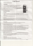
1. Scopeof appliiation
This IushLlatiqoManual suirs for theI iber Opric SpticeClosure(Hereafterabbreviat€dasFOSC),asrhe
gudatrceol properinsLallarion.
Tbe st0F oi applicationisr aerial,undereround,pipeline,ha.d-holes.The ambienttemperarure.dses
eom 4Ot to 6{'t
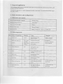
2. Basic structure and configuration
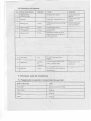
2.1DiEensionand capacity
Ousibdinension(Heishtx
siteqsciuding
Diamorsr)
oltside box)
4 I 5mnLXl90mm
23509-2600g
N@b6 of inletoutlerports
Dill]Eroff,be'
Labic
O Smm-O20mm
CaFciry'ofFOSC
B&chy: l2-96(cores),
Ribbon:up to 288(cores)
22 Main cornponents
NoI
Nane ofcomponents
Quantiq
Usage
FOSCcover
Fiber opiic splice tray
2
Remarks
Heightx Diameter
Max. 6 tmys
(bnrchy)
Fixinghearshrinkable
(ribbon)
holdiryfibere
Bunchyrl2.24(corcs)
Ribbon:6(piecas)
(EOST)
Fib€r holding tray
Floldingfibetswith
Base
Fixilg internal and extenal
1
FixingbeNeenFOSC
6
Sealfittitrg
SealingbetweerFOSC
7
Pressu.e
testingvalve
A iter injccrair itis.usedfor
pressure
testlngad sealhg
testing
8
Earthingderiving
Defivingmetalparrsof
fibercablcsitr FOSCibf
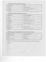
2.3 DimeNion and capacify
No.
Name ofaccessories
Quantity
Usag€
Protcctingfi bersplices
f , n g U b c r \ i r h p r u r L ! t i \ ec o d t
2
E J h i d gs j L c
Puitingthroughbcnvcencrrthidg
Scmtcling fibefcdbles
5
IrNiaUingandlighteningnut of
reinlbfccdcoreandnut (plaslic)
l0
Fof Yrll mountinga.d fol€
nugS'ng
llilchedto fibers and flrcd with
ll
l_OSl: mdDagiDgbu11ir:
l2
Pul intoIOSC beforeesalinglor
3. Necessarytools for installation
3.1Supplementary
materinls( to be providedby operator)
Name of maieriah
Usage
Lrbrling ten pon.il). U\ing
Elhyl alcohol
Cleaning
Clcaning
Retrlarks
3.2 Specialtools(lobe providedb) operator)
Nane oftools
Usage
Cutling offilbercablc
Strip olfprotective coat offibe. cable
AssemblingFOSC
33 Liniversal toole( to be provided by operator)
Nameoftools
Usrgeand sp€cification
Mcasurins1lbff cable
Takr onprorcc !e coaf offibir cabte
Cullingoff reinforcedcore
C r c s s i n e / P a m l l esl jcnfg( * d r n e r
!ri-:!:
Waterp.ooidusLproof
Tighteninenut of reinntrced core
3..1Splicingand testinginstrumetrts( to be proyidedby operator)
\ame ofinstruments
Usage and specification
F-LiotrSplicingMachine
O]DR
Splicingtesling
Pro!isionalsplicingtools
\otice: The above-mentioned
tools andtestinginstrumentsshouldbe pfovided by the operatore
lnemselves.
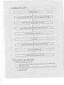
4. Installation flow ch4rt
l OPenthe closure
-F-_rI
I
.Il*,...ni*
t"ne,h or nber crble to be fi)'edand rlripped
inqideFosc
and fiber
3. Strip off protectivecoatsoffiber cabl€
I
I
-s"pn*t"
fixins liber
nl*. *."" o"d preparework priorto
I
I
I
I
5. Fix fiber cableand reinforcedcore
I
I
6' Splicenbers
I
I
?t*,u,,
housefibers
n"u, ro.tnuobleprot€ctiveslcevesnd
L
I
8. Check uP colnPrehensivelY
9. AssembleFOSChousirgand fixFOSC
oI installingFOSC'
Tbe process
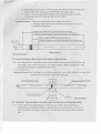
5.1 StePOne-OPenthe closure
to install the FOSC and thefl place
5.1-1 Cleaningthe locale and determinewhere
fibef cablosreqriired'
and accessorieshave been well prepare'l
5.1.2 Check whetherthe rnam compon€nts
iNide the Package'
5.1-3 Open the closure'
O demounthoopfixing bolt andpull hooplockingsystemout, thenproceedir
demourring
thelroop.
@ Pull the FOSCcoverupwardsout, installationcouldbegin.
5.1.4 SceDfa$ing I
Important issues:Ifthe weatherconditionis not goodenough,thena tentmust
'
bepitch€dfor waterproofanddtlstproof.
FOSC hoop(left)
.---
FOSC hoop(right)
o D
Drawing I
5.2 StepTwo-Determinelengthoffiber cableto be fixed an<istrippetlinside
FOSC
5.2.1 O FibercableiD 11omlnlength:thedistancefrom smallgasketring to fibercablc
pressboard.
ra Fibel cablein 1720mmlength:it is usedto bewindedandsplicedafter.
stripping.
Fiber with protective coat in l20mm length: the distancefiom the fixing point
offiber cable to the fixing point ofIOST({iber optic spLiceiray).
g Fiber in I600mm length: aiter stripping offthe prctectibe coat, it is to be
winded inside the FOST after splicing with other fibers5-2.2 SeeDrawing 2
3
Important
issues: L Reserveenoughlengthofliber cableto be spliced.
2. Stripping length also could be decidedby customersaccordingto
installationrequirement.
11(]fln fixing lengthoffiber oableinsideinlevoutlettube
l720mm 1effth ofDrotectivecoat of fiber cableto be srr
1 2 0 m n l e n g t h o f f i b e f w i t h p r o t e c t j b ec o a t
l600mn length ofprotectibe coat offiberto be stripled off
Drawing 2
5,3 Step Three-Strip offprotective coat ofliller cable .nd liber
5.3.1 Stripotl prot€ctivecoatofliber cablefrom thetemp,locatingmarkwith the cutterand
the stipper,ploasercfer to Drawing2 for strippinglength.Strippinglengthalsocouid
bedecidedaccordiigto installationrcquirement.
5.3.2SeeDrawing3.
Important issues:If it is difticuit to pu1lall the protectivecoat offiber cableat onc tiine, strip
it off sectionby sectionto aboid fiber breakage.
Inlcr terminaliber cable
S ni ! ! i n B i e n n i n a il i b ( r ( r h e
Drawing 3
5,4 StepFour- Separatefiber coresand prepirrervork prior to fixing fiber cable.
5.4.I Wind2 layersof insulation
coatoffibercorefoeprotection.
tapeonproteclive
Mwanwhile, get rid ofthc stulling to separatefibel core and clean therr. Form a ring
with the diameterof I00mm or so and fox it on the fiber cable telnDorarilv bv adhesive
tape.
-1'
5-4.2 Reservereinforcedcorein 50lnmlengthandcut offthe ufirecessary
ones.
5.4.3 SeeDrawing4.
Important issuesiInlet/oDtlet
tubesareto beselect€d
accurately
to makeit easyfor splicing
andsealing.
I
c
60
I
!
t
l
a
3
0
:
0
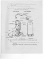
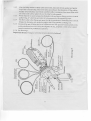
Fix reinforecedcore,.nd pyrocondense,
fL{ and sealliber cable.
5.5.1ThisIOSCis plobided
tubes,
rhi;h suitsforllbercable
withmax.
with4 inlet/outlet
Diam€t€l@ 16nm.
5.5.2
After deciding number offibe. cable inlet/outlet,delnoulrtthe nut, gasketand gaskef
ring ofthe coresponding inlet/outlet tub€saccoiding to the diam€ters
offiber oaores
actually to be installed, insert them into fiber cable in sequence,fien insert
fiber cable
into inlet/outlet cable, tighten the nut ;n order to seal orcDerlv
5-5.3 While diameteris small enlargethe dianeter w ith sealtape
at fixing position ofsmall
gasketring, ofwhich the perimeteris to be measuredwith measuringpaper
5.5.4 Fix fiber cable to rhe fixing seat,pr€ssit with the pressboard.
While liameter istmall,
enlargethe diameterwiih insulatior tape at the fixing pseition offixing
s€at.
5.5.5 Demount the nui offixing device ofreinforced corc with
specialwrench lplastic one),
setthe reinforced core into fixing slot, tighten the nut, retighten it with
metal wrench
(metal wrench to be probided by operator).
5.5.6 SeeDralving 5.
Important issues: Fixing nut ofreinforced core shouldbe tiehtened.
qD
i
I
U i
;i
ii:
';
i.
1>,
nl
Tt
a
!
:
€E
5.6 Step Six-Splicelibers
5.6.1 Follow usermanualof fusjonsplicingmachineto splicefiber'
Imporfant issues: Pay attention to the twist and bend offiber
5.7 Step Seven- Install heat shrinkable protectibe sleeveanalhouse fibers.
5.7.1 Whenhavingcompletedsplicingthefibers,the firstfiber ring shouldbehoused
on the fatthestsideofFOST.Theremainitgfiber shouldbe winded'forminga ring
with diameiernot lessthan80mm,thenput it into FOST(FiberOptic SpliceTray)
togetherwith heatshrinkableprotesttvesleeve.
(Firstlyfix heatshrinkableprotectibesleoveirto the slot,thenenlargethe diameterof
fiberringproperly.)
5.7.2 SeeDrawing6
Impoitatrt issues: Pay attention to the tlvist and bend offiber
slocvc(buncl'yor ribbon)
D r a w i n g6
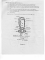
5.8 StepEight - Ch€ckup comprehensively
.To ensu.ethe technical requirem€l1tsthe following instructionsmust be followect:
5.3.1 Fibers with protective coatarefixed with nylon tie atthe
€ntranceofFOST.
5.8.2 crommet should be pressedfrom inside to outside in order properly
to
install IOST.
5-8.3 Ifthere are fibers wirh protective coat rese ed available wind
it into the tib€r hotding
tmy.
5.8.4 Check whether the internal tightene.sand reinforced
core are welt tighrened.
5.8.5 Check rrhether gasketring is installedneatly and snoothly
without any breakage.Tf
not leve it up with sealtape.
5.8.6 SeeDrawing7.
Important issuesiIfany p.oblemsoccur,theyshouldbe solvedrighl
away.
D r a w i n g7
t0
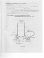
5.9 StepNine - AssembleFOSC housingard Iix FOSC
5.9.1putFOSCcovcronli?sedire€rly.
5.9.2 Install ptasric hoop betwee! FOSC cover anclthe base,tighten hoop locking sysrem,
which is to be tixed try hoop fixing bolt rhl)n.
i.9.3 All nuts (plastic ones) ofbase needto be retightenddonce more.
5.9.4 IOSC installation
O Acrirl applicat;on:fix metal hoop and transomto the pole. pleaserefer to Drawing 8
,? Will flountilg application: Iix
the bracketon the wall w;th the bott.(metalhoop is
not required.)
O Undergroundapplication: metathoop is not required.
5.9.5 Seedrawine8
'f
Important issues:1. Payattentiorwiile installingplastichoop.
2. The specification
ofthe bolt for wall_mounting
is M8.
ell
D r a w i n g8
.l
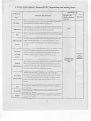
6. Fiber Optic Sptice Closures(IOSC) inspecting and testing items
Routine test
(Before leaving
factory)
Technical Requirenents
Erch snrallpackrsecontxinsonDfiberoptiospliceclosurc,rogelherwith
iis accc$oriestoos,insiallarion
nanualandpacki.glisi.
Intrcl in shape.no bu.n, bnbblcs,chdps,pores,waqrs,nnpurniesandorher
deiech,all backgrcundcolosshouldbeevenandconrlnldt.
Thcrcisa clearsignon thehousing,suchasnanc andmodetoilheprcduct
Thetibes Eseryedareio bewindcdin fibcr opticsplicerratrFOST).
the
Fiber storage
lengihoriibea housedinIOSTis>1.6m thecufrcdradiush >30nn
Duringthe installdionandfraint€nance,
theE shouldbcno ahenurrio.
onnbe6
trlectricnl
joiriing
InsideFOSC:nclauioconporenhoffiborcablcshisthennctio.sof
e|ec(rcalputturgthroush,
ea hnrscomectionanddisconnectnrgrt is
' o . b l e r o i 1r , - , f i l o J c r . \ . n . . e \ r c c o d
' eIr'',|
At l€ast3
08.
sampled
At Ieast3 sets I eachrime
Alierseali.g accodinglo thestipuiatedopcralion
prooedurcs.
lhe joieoted
S€aling
atr fre$ure is looKPal5Kpa, whenimneGedin ciea.w.rer ornornal
temperalure
1brIt minutes,rhcrcshouldbeno rn bubbles,
Lhenobse^ed
lbr z4 hous, thereshouldbeno cha.georan prcssuE.
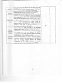
Atter reoteningandresealine
according
10thcsripulared
opcrarion
Re-sealing
procedu.es,
ihc inj.crcdai pres e is l00ktatsKpa.vhcn rrrm.seo n
clea. waterofnomal ictupemtuEfor l5 ninutes.lheresioutd bc no rir
b u b b l e ish c n o b s e r y e d f o .h2o4u s ,t h c o s h o u l d b e ncoh r . : r . : i .
i
Bearingpullis>S00N at .xic oriDntaLion
,theEshouldbeno bc.kaee
Punching
Bciinepressurcof2000N/locnlor I ni.u!cs,thercshoutqoeno
breakd-qe
on lhe housing
B e a r n r g i m p a o l e n e r el 6
t oNf . d , 3 l i m e s o f i m p a c r s r h e E s h o u l d b e n . l
brcakage
oo the housing
)2
The rpot beiween the FOSC and seal fitting can bear
bendinglensionof 150Na! bendingatgle of 1450 for 10
circles,the.e shouldbe no breakageot the housing
B eari.g :orsion50N'm, I 0 circleat torsionangle+9o*
There should be no breakageon the housing'
lnjecledair prcssureof 60KPai5 KPa,the temperature
circlerangingfrom _40C'+65C, 10timesofthe circular
for 2 hours
of hightenperalure
tests(onecircularconsists
Temperatsre + indoor temperaturefor 2 hours+ low tempemturefor 2
f;or 2 hours ) when the
hours + indoot lemperature
circle
the
pressure
declines,the amplitudejs =sKpa' immerse
for 15
swatchit clean water of normaltemperature
thereshouldbeno a;rbutbles
minutes,
Voltage
resistaEce
strergth
After sealing the FOSC according to the stipulated
operationprocedures,immerseit in cleanwaterofnormal
temperalurein 1.5m depth for 24 hours,ihere shouldbe
no breakdown or ar! over between ihe metallic
componentsof the FOSC, betweenmetallic components
andthegrourdai DC I sKvlFll1lglli
Isolathg
iesistance
operation
to stipuiated
An", ."uiing ttt" losc according
procedwe,immerseit in cleanwaterin 15m depthfor
24h, the :solating resistancebetweenthe me:allic
componentsof the FOSC, between the metallic
andthegrounqlE!19]1-!1yg
components
l3