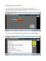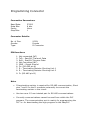
1
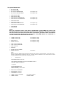
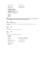
Easy PLC micro User Manual WARNING! The Easy PLC has been designed for use in multiple applications. It is practically impossible to test the performance, or assess the suitability of the Easy PLC, in any or all of them. Please assess the suitability of using the Easy PLC micro for your application before using it. We will not be responsible in any way for any results, which you may achieve by using the Easy PLC micro either correctly or incorrectly. Be careful while downloading the program to the Easy PLC micro which is connected to a machine which is powered up. The download could trigger an erratic operation which can be dangerous to equipment and personnel. The Easy PLC Programmer software has been developed as an aid for programming the Easy PLC but has not been extensively tested or debugged. The syntax and error detection capabilities have not been ascertained rigorously. Kindly follow the syntax of statements as shown in the manual to prevent errors. Incorrect use of Easy PLC micro can result in damage to equipment, machinery and/or personnel. Be careful! Easy PLC micro and other PLCs from the family are recommended to be used by trained personnel only for real life applications. EASY PLC micro Specifications: Power Supply: 24VDC +/- 10% @250mA 5 Digital Inputs – 24 VDC (Logic 0 = 0 to 12VDC, Logic 1 = 18VDC to 30VDC) (2 High Speed Inputs for counting or encoder feedback – not tested/implemented) 4 Digital 24VDC / Analog Inputs 0-10VDC (13 bits resolution with DRE technology) 6 Digital Outputs 24VDC @0.5A / Optional 4A can directly drive solenoid valves Sink Type – Open Collector. Free Wheeling Diodes for inductive loads built in. (2 PWM outputs, can drive proportional valves, 1 PTO output for servo drive – not tested /implemented) 256 Memory Flags (240 General Purpose + 16 special Flags) 64 Timers (0.1 sec to 3276.7 sec) / Counters (0 to 32767) 128 Datawords for storage of parameter values / 64 datawords for temporary data 32 Messages for display of 16 characters each 64 subroutines with nesting depth of 8 routines Cycle time 4.6 milliseconds / 1000 statements approximately 2000 statements Program Memory Built in HMI – 16x2 LCD display + 16 key Keyboard 8 keys PB1 to PB8 can be used in PLC program Information display for status of Inputs and Outputs 1 x RS232 / RS485 port for interface to PC Execution Structure: The Easy PLC like almost all other PLCs operates in an infinite loop which has the following form. GET INPUTS EXECUTE LOGIC PROGRAM WRITE OUTPUTS The PLC reads all inputs. Then executes the logic program and generates outputs which are stored in the outputs image in the PLC memory. The outputs image is then dumped on to the terminals in the third and final step. The program execution loops back and executes the process infinitely. Instructions: Note: In the following, element is the name of INPUT, OUTPUT, FLAG, TIMER, COUNTER, DATAWORD, SUBROUTINE, MESSAGE, ANALOGINPUT or ANALOGOUTPUT except as noted. Assignment Statements: element IS INPUT For e.g. START_PB IS INPUT 3 n (0-8) element IS OUTPUT For e.g. FWD_SOL IS OUTPUT 1 n (0-5) element IS FLAG n (0-239) For e.g. SEMIAUTO_MODE IS FLAG 36 element IS TIMER n (0-63) For e.g. COOLING_TIMER IS TIMER 24 element IS COUNTER n (0-63) For e.g. NO_OF_PIECES IS COUNTER 10 element IS DATAWORD n (0-191) VALUE n FORMAT $$$$$ n = -32768 to 32767 $$$$$ = XXXXX or XXXX.X or XXX.XX or XX.XXX or X.XXXX or .XXXXX Value of datawords 0 to 127 is retained in Power off condition and hence should be used for storing set values and timer values. The value of datawords 128 to 191 is not retained in Power Off condition and hence should be used to store intermediate and final results of calculations during scaling and other functions. For e.g. COOLING_TIME IS DATAWORD 24 VALUE 300 FORMAT XXXX.X (cooling time of 30.0 secs) element IS SUBROUTINE n (0-63) For e.g. MANMODE_RTN IS SUBROUTINE 3 element IS MESSAGE For e.g. IUF_MSG IS MESSAGE n (0-31) VALUE cccccccccccccccc (16 chars) 15 VALUE INJ_UNIT_FORWARD element IS ANALOGINPUT n (0-3) For e.g. MOLD_POS IS ANALOGINPUT 0 element IS ANALOGOUTPUT n (0-1) For e.g. FLOW IS ANALOGOUTPUT 1 Note: Spaces are not allowed in Parameter names and messages. Use hyphen. It is displayed as space character Program Statements: IF IF IF IF element element element element ON OFF RISINGEDGE FALLINGEDGE AND AND AND AND OR OR OR OR AND BLOCK OR BLOCK element element element element element element element element ON OFF RISINGEDGE FALLINGEDGE ON OFF RISINGEDGE FALLINGEDGE for inputs only for inputs only for inputs only for inputs only for inputs only for inputs only Note: Every ‘IF’ statement starts a new block. ‘AND BLOCK’ logically ANDs the result of the last block with the result of the block just before that. Similarly, ‘OR BLOCK’ logically ORs the result of the last block with result of the block just before that. A maximum of nine IF statement blocks can be used before using ‘AND BLOCK’ or ‘OR BLOCK’ or else the result of the first block will be lost. THEN element ON THEN element OFF for outputs / flags for outputs / flags SET element RESET element for outputs / flags for outputs / flags CALL element IFTRUE CALL element IFFALSE CALL element RETURN START element TIMER RESET element for timers Note: Before using the START Timer instruction, load the timer value in the accumulator. Timer values are stored in the datawords numbered 0 to 127. All timers have a resolution of 0.1 seconds hence a value of 107 indicates a time value of 10.7 seconds. For e.g. * Assignments DECOMPRESSION IS FLAG 30 COOLTIME IS DATAWORD 10 VALUE 100 FORMAT XXXX.X COOLING_TIMER IS TIMER 21 * Program IF DECOMPRESSION ON LOAD COOLTIME START COOLING_TIMER TIMER SET element COUNTER INCREMENT element DECREMENT element LOAD element COUNTER LOAD element for counter values for data words STORE element for data words READ element STORE element for analog inputs for analog outputs COMPARE COMPARE COMPARE COMPARE COMPARE COMPARE ADD SUBTRACT MULTIPLY DIVIDE IF IF IF IF IF IF EQUAL NOTEQUAL GREATER GREATEROREQUAL LESS LESSOREQUAL Note: Load first dataword, Load second dataword, Comparison is always done of first dataword with second dataword. Numeric operation follows the same order. For e.g. LOAD DW1 LOAD DW2 COMPARE IF GREATEROREQUAL The above statements check if DW1 >= DW2 and the RLO (Result of Logic Operation) is updated accordingly. LOAD LOAD SUBTRACT DW1 DW2 The accumulator holds the result of DW1 – DW2. LOAD LOAD DIVIDE DW1 DW2 The accumulator holds the result of DW1 / DW2. PWM ON PWM OFF PTO ON PTO OFF not currently implemented not currently implemented SUBROUTINE element for subroutines only DISPLAY element for messages only END PROGRAM END FILE Program Structure: All assignment statements are entered first, followed by program statements. After the logic program is entered it must be followed by END PROGRAM statement which indicates end of the logic program. Following the END PROGRAM statement, write all the subroutines. Each subroutine ends with a RETURN statement. The last instruction in the program must be the END FILE statement which indicates the end of the entire program. The structure of the program is indicated below. Note: All lines beginning with asterisk ‘*’ are treated as comments and are ignored. * Assignment Statements . . . * Program Statements . . . END PROGRAM SUBROUTINE element . . . RETURN SUBROUTINE element . . . RETURN END FILE Template File A template file has been provided with predefined names for all Inputs, Outputs, Flags, Timers/Counters, Subroutines, Messages, Data words, Analog Inputs Analog Outputs and all the special flags defined in the EasyPLC. This file should be copied and pasted into new application program and the names changed as per the requirements of the application. Unwanted names may be retained or may be dropped. This will make the job of developing the applications easier. Programming Examples Subroutine Test * Subroutine Test Program * The program toggles two outputs M1 and M2. When M1 is ON the program calls * subroutine 1 and when M2 is ON it calls subroutine 2. Subroutine 1 displays message * “Subroutine 1” and subroutine 2 displays message “Subroutine 2” * Define Outputs M1 IS OUTPUT 1 M2 IS OUTPUT 2 * Define timer values M0_TIME is not used M0_TIME IS DATAWORD 0 VALUE 256 FORMAT XXXX.X M1_TIME IS DATAWORD 1 VALUE 10 FORMAT XXXX.X M2_TIME IS DATAWORD 2 VALUE 10 FORMAT XXXX.X * Define Timers M1_TIMER IS TIMER 1 M2_TIMER IS TIMER 2 * Define Subroutines MODE1_RTN IS SUBROUTINE 1 MODE2_RTN IS SUBROUTINE 2 * Define messages SUB1_MSG IS MESSAGE 1 VALUE SUBROUTINE_1 SUB2_MSG IS MESSAGE 2 VALUE SUBROUTINE_2 * Switch ON output M1 IF M1 OFF AND M2 OFF SET M1 IF M1 ON LOAD M1_TIME START M1_TIMER CALL MODE1_RTN IFTRUE IF M1 ON AND M1_TIMER ON RESET M1 SET M2 IF M2 ON LOAD M2_TIME START M2_TIMER CALL MODE2_RTN IFTRUE IF M2 ON AND M2_TIMER ON RESET M2 SET M1 END PROGRAM SUBROUTINE MODE1_RTN IF M1 ON DISPLAY SUB1_MSG RETURN SUBROUTINE MODE2_RTN IF M2 ON DISPLAY SUB2_MSG RETURN END FILE Scaling * * * * * * * * * Program for scaling of analog input. Input 0 is connected to a Pressure Transducer giving 0-10VDC for a pressure range of 0-250.0 bar. The Signal is simulated by pressing keys PB1 to PB8. 0-10VDC is converted by the PLC to 0-8191 counts. PB1 sets the current pressure value to 1000 counts, PB2 = 2000 counts, PB3 = 3000, PB4 = 4000, PB5 = 5000, PB6 = 6000, PB7 = 7000, PB8 = 8000 Formula Pressure = y = Y2 – (Y2-Y1)*(X2-x)/(X2-X1) where y is current pressure value x is current reading in counts. X1=0, X2=8191, Y1=0, Y2=2500 Format for PRESSURE is XXXX.X * PRESS_VAL IS ANALOGINPUT 0 * Push Button Assignments PB1 PB2 PB3 PB4 PB5 PB6 PB7 PB8 IS IS IS IS IS IS IS IS FLAG FLAG FLAG FLAG FLAG FLAG FLAG FLAG 240 241 242 243 244 245 246 247 * DATAWORDS X1_DATA IS DATAWORD 0 VALUE 0 FORMAT XXXXX X2_DATA IS DATAWORD 1 VALUE 8191 FORMAT XXXXX Y1_DATA IS DATAWORD 2 VALUE 0 FORMAT XXXX.X Y2_DATA IS DATAWORD 3 VALUE 2500 FORMAT XXXX.X PB1_DATA IS DATAWORD 4 VALUE 1000 FORMAT XXXXX PB2_DATA IS DATAWORD 5 VALUE 2000 FORMAT XXXXX PB3_DATA IS DATAWORD 6 VALUE 3000 FORMAT XXXXX PB4_DATA IS DATAWORD 7 VALUE 4000 FORMAT XXXXX PB5_DATA IS DATAWORD 8 VALUE 5000 FORMAT XXXXX PB6_DATA IS DATAWORD 9 VALUE 6000 FORMAT XXXXX PB7_DATA IS DATAWORD 10 VALUE 7000 FORMAT XXXXX PB8_DATA IS DATAWORD 11 VALUE 8000 FORMAT XXXXX * * * * THE FOLLOWING ARE READ WRITE DWORDS AND THEIR VALUES ARE NOT STORED DURING POWER OFF. THESE WORDS ARE TO BE USED FOR CALCULATIONS WHERE ONLY THE CURRENT VALUE IS REQUIRED. FOR EG. IN SCALING ANALOG INPUT PRESSURE IS DATAWORD 128 VALUE 0 FORMAT XXXX.X Y2Y1DIFF IS DATAWORD 129 VALUE 0 FORMAT XXXXX X2X1DIFF IS DATAWORD 130 VALUE 0 FORMAT XXXXX CURRDIFF IS DATAWORD 131 VALUE 0 FORMAT XXXXX TMP_PROD IS DATAWORD 132 VALUE 0 FORMAT XXXXX SUBTRAD IS DATAWORD 133 VALUE 0 FORMAT XXXXX CURR_RDG IS DATAWORD 134 VALUE 0 FORMAT XXXXX * MESSAGES * VALUES ARE MESSAGES TO BE DISPLAYED ON LCD * MAX OF 16 CHARS ALLOWED "_" WILL BE DISPLAYED AS SPACE PB1_MSG PB2_MSG PB3_MSG PB4_MSG IS IS IS IS MESSAGE MESSAGE MESSAGE MESSAGE 0 1 2 3 VALUE VALUE VALUE VALUE PB1_PRESSED_____ PB2_PRESSED_____ PB3_PRESSED_____ PB4_PRESSED_____ PB5_MSG PB6_MSG PB7_MSG PB8_MSG IS IS IS IS MESSAGE MESSAGE MESSAGE MESSAGE 4 5 6 7 VALUE VALUE VALUE VALUE PB5_PRESSED_____ PB6_PRESSED_____ PB7_PRESSED_____ PB8_PRESSED_____ * PROGRAM STARTS HERE IF PB1 ON LOAD PB1_DATA STORE CURR_RDG DISPLAY PB1_MSG IF PB2 ON LOAD PB2_DATA STORE CURR_RDG DISPLAY PB2_MSG IF PB3 ON LOAD PB3_DATA STORE CURR_RDG DISPLAY PB3_MSG IF PB4 ON LOAD PB4_DATA STORE CURR_RDG DISPLAY PB4_MSG IF PB5 ON LOAD PB5_DATA STORE CURR_RDG DISPLAY PB5_MSG IF PB6 ON LOAD PB6_DATA STORE CURR_RDG DISPLAY PB6_MSG IF PB7 ON LOAD PB7_DATA STORE CURR_RDG DISPLAY PB7_MSG IF PB8 ON LOAD PB8_DATA STORE CURR_RDG DISPLAY PB8_MSG * * Use the following 3 lines for using the actual Analog Input 0 instead of the push buttons simulation program above * * * IF ALWAYS_1 ON READ PRESS_VAL STORE CURR_RDG IF ALWAYS_1 ON LOAD Y2_DATA LOAD Y1_DATA SUBTRACT STORE Y2Y1DIFF IF ALWAYS_1 ON LOAD X2_DATA LOAD X1_DATA SUBTRACT STORE X2X1DIFF IF ALWAYS_1 ON LOAD X2_DATA LOAD CURR_RDG SUBTRACT STORE CURRDIFF IF ALWAYS_1 ON LOAD Y2Y1DIFF LOAD CURRDIFF MULTIPLY LOAD X2X1DIFF DIVIDE STORE SUBTRAD IF ALWAYS_1 ON LOAD Y2_DATA LOAD SUBTRAD SUBTRACT STORE PRESSURE END PROGRAM END FILE Sequence Test * * * * * * Many automated machines follow the sequential mode, where different operations are performed in sequential steps. At each step, a set of outputs may be switched ON or OFF. The end of a step is generally decided by an Input or end of a timer. The program is self-documentary, which is an important feature of CLARITY language The program can be written in upper or lower case. The compiler converts everything to upper case while processing step1 is flag 1 step2 is flag 2 step3 is flag 3 step4 is flag 4 step5 is flag 5 continue is flag 6 start is flag 240 st0 st1 st2 st3 st4 st5 is is is is is is output output output output output output 0 1 2 3 4 5 Torqk is dataword 0 value 2500 format xx.xxx s1timer is timer 1 s1_time is dataword 1 value 20 format xxxx.x s2timer is timer 2 s2_time is dataword 2 value 20 format xxxx.x s3timer is timer 3 s3_time is dataword 3 value 20 format xxxx.x s4timer is timer 4 s4_time is dataword 4 value 20 format xxxx.x s5timer is timer 5 s5_time is dataword 5 value 20 format xxxx.x cycles is dataword 6 value 3 format xxxxx cyc_counter is counter 6 s1msg is message 1 value ARM_FORWARD s2msg is message 2 value MEASURE_TORQUE s3msg is message 3 value MEASURE_ANGLE s4msg is message 4 value ARM_REVERSE s5msg is message 5 value ARM_HOME_POS WAITMSG IS MESSAGE 0 VALUE WAIT_FOR_START * Program starts here IF ST1 OFF AND ST2 OFF AND ST3 OFF AND ST4 OFF AND ST5 OFF DISPLAY WAITMSG if start on load cycles set cyc_counter counter reset continue IF START ON or continue on AND ST1 OFF AND ST2 OFF AND ST3 OFF AND ST4 OFF AND ST5 OFF SET ST1 reset continue DISPLAY S1MSG IF ST1 ON LOAD S1_TIME START S1TIMER IF ST1 ON AND S1TIMER ON RESET ST1 SET ST2 DISPLAY S2MSG IF ST2 ON LOAD S2_TIME START S2TIMER IF ST2 ON AND S2TIMER ON RESET ST2 SET ST3 DISPLAY S3MSG IF ST3 ON LOAD S3_TIME START S3TIMER IF ST3 ON AND S3TIMER ON RESET ST3 SET ST4 DISPLAY S4MSG IF ST4 ON LOAD S4_TIME START S4TIMER IF ST4 ON AND S4TIMER ON RESET ST4 SET ST5 DISPLAY S5MSG IF ST5 ON LOAD S5_TIME START S5TIMER IF ST5 ON AND S5TIMER ON RESET ST0 RESET ST1 RESET ST2 RESET ST3 RESET ST4 RESET ST5 decrement cyc_counter if cyc_counter on and s5timer on set continue END PROGRAM END FILE Simple GATES demo * Sample test program to demonstrate simple functions * program segment 1 - a,b,c,d... are part of this single large program. * All inputs, outputs, flags, timers, counters, datawords must be * assigned before they are used in the program. * program segment 1a - AND gate * program segment 1b - OR gate * program segment 1c - NOT gate * program segment 1d - NAND gate * program segment 1e - NOR gate * program segment 1f - XOR gate * program segment 1g - XNOR gate * program segment 1h - Buffer/Follower *************************************************************** * program segment - 1a * AND gate. If Input 0 AND Input 1 are On then output 0 is ON *************************************************************** inp0 is input 0 inp1 is Input 1 out0 is output 0 if and then inp0 inp1 out0 on on on *************************************************************** * program segment - 1b * OR gate. If Input 2 OR Input 3 are On then output 1 is ON *************************************************************** inp2 is input 2 inp3 is Input 3 out1 is output 1 if or then inp2 inp3 out1 on on on ****************************************************************** * program segment - 1c * NOT gate. If Input 4 is OFF then output 2 is ON and vice-versa. ****************************************************************** inp4 is input 4 out2 is output 2 if then inp4 out2 off on *************************************************************** * program segment - 1d * NAND gate. If Input 5 AND Input 6 are On then output 3 is OFF * else it is ON *************************************************************** inp5 is input 5 inp6 is Input 6 out3 is output 3 if and then inp5 inp6 out3 on on off *************************************************************** * program segment - 1e * NOR gate. If Input 7 OR Input 8 are On then output 4 is OFF *************************************************************** inp7 is input 7 inp8 is Input 8 out4 is output 4 if or then inp7 inp8 out4 on on off *************************************************************** * program segment - 1f * XOR gate. If Input 9 AND Input 10 have the same state i.e. both * are ON or both are OFF, then output 5 is OFF else it is ON. *************************************************************** inp9 is input 9 inp10 is Input 10 out5 is output 5 if and inp9 inp10 on off if and inp9 inp10 off on or then block out5 on *************************************************************** * program segment - 1g * XNOR gate. If Input 11 OR Input 12 have the same state i.e. both * are ON or both are OFF, then output 6 is ON else it is OFF. *************************************************************** inp11 is input 11 inp12 is Input 12 out6 is output 6 if and inp11 inp12 on on if and inp11 inp12 off off or then block out6 on ****************************************************************** * program segment - 1h * Buffer or Follower gate. If Input 13 is ON then output 7 is ON * and vice-versa. ****************************************************************** inp13 is input 13 out7 is output 7 if then inp13 out7 on on end end program file Programming Software Write the PLC program in Notepad or similar editor and store it as a simple text file. To program the Easy PLC micro, run the Easy PLC Programmer software and follow the steps below. One the first page, choose a COM Port of your PC using the drop down list box and pressing SELECT button. There must be no error the “comm err” box. Go to the next page (TAB) and press the LOAD FILE button to load the file. Any final editing if required can be done here. Remember to save the file if changed using the SAVE FILE button. Go to compile page (TAB) and press the compile button to compile the program. Errors if any will be shown in the “Errors” box below. Also, the line containing errors will be highlighted in RED in loaded file on the EDIT page and focus will shift to the last line containing the error. Once the program is error-free then, go to the WRITE page and press the WRITE button to write the logic program to the PLC memory. This overwrites the earlier program in the PLC. Also ensure that the PLC is connected to the PC using cable provided for the purpose. WARNING! Be careful while downloading the program to the Easy PLC micro which is connected to a machine which is powered up. The download could trigger an erratic operation which can be dangerous to equipment and personnel. Please assess the suitability of using the Easy PLC for your application before using it. We will not be responsible for in any way for any results that you may achieve by using the Easy PLC micro either correctly or incorrectly. Once the program has been downloaded then monitor and debug the program using the MONITOR page and pressing the MON ON button. Before leaving the page, kindly ensure that the MONITOR mode is switched OFF using the MON OFF button. Pressing EXIT will exit the Easy PLC Programmer software. Easy PLC micro can be put in RUN mode or STOP mode and can be RESET using the buttons provided for the purpose. DATAWORD values can also be changed using the controls provided for the purpose. To RUN, STOP and RESET the PLC the Monitoring mode must be ON. The MONitor mode ON is indicated by a green lamp named MON as shown in the image below. RESET PLC works only when the PLC is in STOP mode. To RESET PLC first press STOP button once and then press the RESET button once. PLC can then be put in RUN mode. The FIRST_SCAN flag (Flag 253) is ON after this software RESET. Easy PLC Front Panel Keypad Operation The Easy PLC front panel has a 16 key keypad. The various keys on the front panel and their functions are as follows: i Key – The “i” key is the information key. It toggles the display between the normal mode display and the status display. The status display, displays the state of all the inputs and outputs. This helps in debugging an application and aids in fault finding and diagnostics on a machine. SET key – The SET key is used for setting the values of Data words. To change the value of a data word, please use UP and DOWN keys to display the data word and then press the SET key. This changes the mode of keypad to “edit mode”. In this mode PB1 to PB8 work as numeric keys 1 to 8. The “edit mode” can be ended only by pressing either the CAN key or the ENT key. CANcel key restores the original value of the data word and ENTer key stores the new value of the data word. UP and DOWN arrow keys – The UP and DOWN arrow keys are used to scroll UP and DOWN through the list of data words from 0 to 191. By pressing the UP or DOWN arrow key continuously the data words are scrolled in up and down direction till it reaches either data word 0 or data word 191. PB1-1 to PB8-8 keys – The PB1 to PB8 keys function as Push Button keys in the normal mode and function as numeric keys 1 to 8 in the “edit mode”. Multiple key presses are not allowed. A key has to be released before another key can be recognized. So PB1 to PB8 work like Push-to-ON push buttons with NO contact. The state of the keys PB1-PB8 is represented in the PLC as flags 240-247 respectively. DW-9 Key – The DW-9 key is used to display a particular Data word in the display. Press DW key once and display asks for the data word number. Use the numeric keypad to enter number from 0 to 191 and then press the ENTer key to display that data word. In the “edit mode” this key functions as numeric key 9. - or 0 Key – The “minus” or “-“ key works only in the “edit mode”. Pressing the key first in the “edit mode” signals the entry of a negative number. The first key press is treated as “minus sign”. In subsequent key presses, this key functions as numeric 0 key. CAN Key – The CAN key or the CANcel key is used to cancel the “edit mode” and restore the original value of the data word before entering the “edit mode”. CAN key only functions in “edit mode” and has no operation in normal mode. ENT Key – The ENT key or the ENTer key is used to store the new value of data word to the memory and exit the “edit mode”. ENT key only functions in “edit mode” and has no operation in normal mode. Wiring Diagram AI 0 DI 8 9 AI 1 DI 7 AI 2 DI 6 8 7 AI 3 DI 5 6 DI 4 5 DI 3 4 DI 2 3 DI 1 2 DI 0 1 +24VDC Power Supply 0VDC DO 0 10 Relay/Sol DO 1 11 Relay/Sol DO 2 12 Relay/Sol DO 3 13 Relay/Sol DO 4 14 Relay/Sol DO 5 Relay/Sol 15 +24VDC 16 0VDC Earth 17 18 Programming Connector Connection Parameters: Baud Rate: Data Bits: Parity: Stop Bits: 57600 8 bits None 1 Connector Details: No. of Pins: Gender: Type: 9 PIN Female D Connector PIN functions 1. 2. 3. 4. 5. 6. 7. 8. 9. Not connected (NC) TxD – EasyPLC Transmit Data RxD – EasyPLC Receive Data Not Connected (NC) GND – Signal Ground D+ (RS-485 pin A) R – Terminating Resistor Shorting Link 1 R – Terminating Resistor Shorting Link 2 D- (RS-485 pin B) Note: If terminating resistor is required for RS-485 communication, Short pins 7 and 8 on the D connector externally to connect the terminating resistor in the circuit. Use two core 0.5 mm twisted pair for RS-485 communications. Currently communications cannot be used from within the PLC program. The communication port is mainly for programming the PLC i.e. for downloading the logic program to the EasyPLC.