1
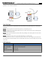
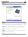
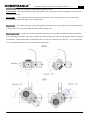
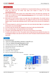
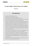
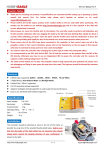
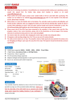
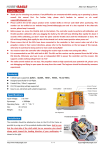
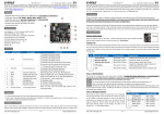
Brushless Gimbal Controller User Manual F/W Ver.1.0 1 Features 2-axis stabilization for roll and pitch. Self-tuning PID control algorithm is used to make it much easier to setup. Easy-to-use program card which supports both Simplified Chinese and English. 2 RC modes supported including Position Mode and Speed Mode. Adjustable angle limits for both axes, roll: 45°~+45°, pitch: -90°~+135°. ±45° adjustable initial angle offset for both axes. The firmware can be upgraded very easily. Specifications Input Voltage: 7.4V~12.6V (2S/3S Lipo battery with JST connector, 2S/7.4V is recommended) BEC Output: 5V, only for the receiver. Gyroscope: ±1000 dps Accelerometer: ±2g Max Current: <5A PWM Frequency: 62.5kHz(Noiseless) Motor Update Frequency: 1kHz Operating Temperature: -40 ℃ ~ 85 ℃ Size: 50×50mm Weight: 19g (including sensor and wires) Package Contents HTTP://WWW.HOBBYEAGLE.COM Oct. 18, 2013 2 Brushless Gimbal Controller User Manual F/W Ver.1.0 (1) Controller × 1 (2) Sensor × 1 (3) Sensor Wire (25cm) × 1 (4) Receiver Wires (15cm) × 2 (5) USBKEY × 1 (6) Data Cable (40cm) × 1 (7) Double-sided tapes × 1 (8) * Program Card × 1 (optional) Connection Connect the board to the receiver and the sensor according to the illustration below. One thing to note is that the controller provides 5V output voltage through the pins “RX-1” and “RX-2” which can be used as the power supply for the receiver (receiver only, don’t use to driver the servos). If your receiver has been powered from other device such as an ESC, BEC or battery, you need to pull out the middle red wire and keep it unconnected. You might not even connect these 2 channels if you don’t want to control the gimbal via radio. Sensor Mounting The sensor should be mounted on the camera by using the provided double-sided tape. There are two mounting ways: face up and face down. Default is face down. Once mounted, you need to choose the correct mount orientation using the program card or config tool. When mounting, make sure that the white arrow is along with the heading direction HTTP://WWW.HOBBYEAGLE.COM Oct. 18, 2013 Brushless Gimbal Controller User Manual F/W Ver.1.0 3 of the gimbal and locate the sensor as close to the CG of the gimbal as possible. A neat wiring is needed to leave the gimbal free to move without any hindrance. Start Up Steps Before use, make sure that a CG adjustment has been well performed for the gimbal and power on it following the steps below. Step 1 Move the gimbal back to the horizontal position by your hand then power on. Step 2 The Blue LED will start flashing rapidly for about 3 seconds, which means the sensor is initializing, don’t move the gimbal during this phase. Step 3 After successful initialization, the Blue LED will keep flashing 3 times and the gimbal will start to find its initial position slowly. Step 4 The gimbal is ready to work once the Blue LED changes to a continuous light. The Red light will turn on if there is a communication failure with the sensor, when it happens, please double check the connection between the board and the sensor. The Blue LED on the sensor is just used to display the power status of the sensor. LED Indicator Color Description Blue, Fast Flashing Sensor initializing, don’t move the gimbal until initialization is done. Blue, 3 Slow Flashes Find and return to the initial position. Solid Blue Ready to work. Blue&Red, Fast Flashing Stick centering. Solid Red Sensor error. HTTP://WWW.HOBBYEAGLE.COM Oct. 18, 2013 4 Brushless Gimbal Controller User Manual F/W Ver.1.0 Config Tool The config tool can be downloaded from our website following the link below. We also provide a step by step instruction to help you complete the installation. When the controller is working (solid blue), connect it onto the USB key using the data cable, run the tool to start setting. http://www.hobbyeagle.com/bgc/ Operations To read the settings from the controller into the tool, select the correct port number in the drop-down box next to the "Select Port" and click the button "Read". If the port is not found in the list, try to click the button to refresh. Once read, you can find the current firmware version number next to the “F/W Version”. When you finish with the settings, click the button "Write" to save them into the controller. The new settings will take effect immediately without a restart. Once saved, a message will be shown in the status bar. Save current settings as a file (*.epp file) on your PC. Load settings from an archive file (*.eep file) on your PC. After loaded. you can continue to modify the settings or click "Write" to save them into the controller. Reset the controller to the factory default settings. HTTP://WWW.HOBBYEAGLE.COM Oct. 18, 2013 5 Brushless Gimbal Controller User Manual F/W Ver.1.0 Click this button in the “Device” tab to perform a stick centering, before doing this, move the sticks (may be a slide lever or knob of your transmitter) to the middle position. While centering, both the Blue and Red lights will keep flashing very rapidly, don’t move the sticks until centering is done. The sensor will perform a calibration after power on automatically. When the controller is operating, you can make it recalibrate by clicking this button. While calibrating, the Blue light will keep flashing rapidly for about 3 seconds, don’t move the gimbal until the calibration is done. Parameters Sensor Mounting It is used to select the correct mount orientation of the sensor. Incorrect setting will result in a complete failure. Gyro Direction After installation, you have to check whether the gyros compensates in the correct direction or not. To perform the examination, first turn the gyro gain to 0% and the acc gain to a lower volume (e.g. 10%) . Rotate the gimbal to a certain angle lightly by your hand, after releasing it, you will see the gimbal begin moving back to the starting position very slowly. If not, reverse the gyro direction on that axis. Power It is used to adjust the maximum driving voltage of the motor PWM. The adjustment range is 0-100%. The higher the volume, the larger the torque of the motor, and the heavier the gimbal it can drive. But too large power setting might lead to an increase in the working current and consumption. If you are using a 2S lipo battery and a GoPro camera, a setting about 30-45% will be enough. Angle Offset It is used to specify the initial angle of the gimbal for both axes. The adjustment range is -45°~ +45°. The default is 0°, which means that the gimbal will always maintain level position during flight. Gyro Gain It is used to adjust the gain of the gyro. Gyro makes a dynamic correction so the gimbal can always return to its initial position very quickly even if the plane keeps swinging strongly. We provide you 0-200% adjustable range to meet the needs of different gimbals. Please note that an excessive gain might result in vibration of the motors. You need to fine-tune it and get the best result. Acc Gain It’s used to adjust the gain of the accelerometer. Unlike the gyro, the accelerometer makes a static correction to the gimbal so it can return to its initial position very accurately. The accelerometer will not stop reacting until the error (error between the current position and the initial position) disappears. After you rotating the gimbal to a certain angle lightly by your hand, you will see that the gimbal begin moving back to the starting position very slowly. The larger the gain is, the faster the movement will be. We also provide you 0-200% adjustable range for fine-tuning. An excessive acc gain might cause it to swing back and forth near the initial position. HTTP://WWW.HOBBYEAGLE.COM Oct. 18, 2013 6 Brushless Gimbal Controller User Manual F/W Ver.1.0 RC Mode There are 2 modes for controlling the gimbal by radio. Position Mode The stick controls the angle of the gimbal. Once you release the stick, the gimbal will return to its starting position then. Speed Mode The stick controls the moving speed of the motor. Once you release the stick, the motor stops moving and the gimbal will stays at the current position. RC Rate It’s used to specify the speed of the gimbal movement when you moving the sticks of the transmitter. A range from 0% to 10% can be adjusted and the default setting is 5%. Angle Limits It’s used to specify the maximum rotation angle of the gimbal on both side of the roll and pitch axes controlling by the radio. The positive number represents the maximum angle and the negative number represents the minimum. The maximum angle is limited between -45° and +45° for the roll axis, and -90°~+135° for the pitch axis. The illustration below shows you the definition of the angle. HTTP://WWW.HOBBYEAGLE.COM Oct. 18, 2013 7 Brushless Gimbal Controller User Manual F/W Ver.1.0 Program Card You can also use the program card for setting the controller. But please note that the card needs to be upgraded to Ver.2.2 (or above) or it can not identify the controller. Please visit our website to get the instructions of the program card. All the functions and parameters will be similar whether you are using the config tool or a program card. HTTP://WWW.HOBBYEAGLE.COM Oct. 18, 2013