1
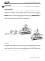
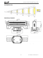
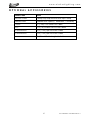
user manual E L A TI ON | ACL 360 BAR™ | user manual
ACL 360 BAR™
www.elationlighting.com
©2015 ELATION PROFESSIONAL all rights reserved. Information, specifications,
diagrams, images, and instructions herein are subject to change without notice.
ELATION PROFESSIONAL logo and identifying product names and numbers herein
are trademarks of ELATION PROFESSIONAL. Copyright protection claimed includes
all forms and matters of copyrightable materials and information now allowed by
statutory or judicial law or hereinafter granted. Product names used in this
document may be trademarks or registered trademarks of their respective
companies and are hereby acknowledged. All non-ELATION brands and product
names are trademarks or registered trademarks of their respective companies.
ELATION PROFESSIONAL and all affiliated companies hereby disclaim any and all
liabilities for property, equipment, building, and electrical damages, injuries to any
persons, and direct or indirect economic loss associated with the use or reliance of
any information contained within this document, and/or as a result of the improper,
unsafe, insufficient and negligent assembly, installation, rigging, and operation of
this product.
Elation Professional USA | 6122 S. Eastern Ave. | Los Angeles, CA. 90040
323-582-3322 | 323-832-9142 fax | www.elationlighting.com | [email protected]
Elation Professional B.V. | Junostraat 2 | 6468 EW Kerkrade, The Netherlands
+31 45 546 85 66 | +31 45 546 85 96 fax | www.elationlighting.eu | [email protected]
DOCUMENT
VERSION
Please check www.elationlighting.com for the latest revision/update of this manual.
Date
Document
Version
Software
Version
DMX
Channel
Modes
Notes
IU01: ≥1.12
8/5/15
1
2U01: ≥1.06
17 / 19 / 43
Initial release.
3U01: ≥1.12
2
ACL 360 BAR™ User Manual Ver 1
www.elationlighting.com
CONTENTS
General Information
4
Warranty
6
Safety Instructions
7
General Guidelines
8
Fixture Overview
9
Fixture Installation
10
Fixture Menu
13
DMX Channel Functions And Values
18
Error Codes
23
Cleaning and Maintenance
24
Technical Specifications
25
Optional Accessories
27
3
ACL 360 BAR™ User Manual Ver 1
www.elationlighting.com
GENERAL INFORMATION
INTRODUCTION
Congratulations, you have just purchased one of the most innovative and
reliable lighting fixtures on the market today! This fixture has been designed to
perform reliably for years when the guidelines in this booklet are followed. Please
read and understand the instructions in this manual carefully and thoroughly
before attempting to operate this unit. These instructions contain important
information regarding safety during use and maintenance.
UNPACKING
Every fixture has been thoroughly tested and has been shipped in perfect
operating condition. Carefully check the shipping carton for damage that may
have occurred during shipping. If the carton appears to be damaged, carefully
inspect your unit for
damage and be sure all accessories necessary to
operate the unit have arrived intact. In the event damage has been found or
parts are missing, please contact our customer support team for further
instructions. Please do not return this unit to your dealer without first contacting
customer support at the number listed below. Please do not discard the shipping
carton in the trash. Please recycle whenever possible.
BOX CONTENTS
(1) Omega Bracket
(1) powerCON Cable
Manual & Warranty Card
4
ACL 360 BAR™ User Manual Ver 1
www.elationlighting.com
CUSTOMER SUPPORT
Elation Professional® provides a customer support line, to provide set up help and
to answer any question should you encounter problems during your set up or
initial operation. You may also visit us on the web at www.elationlighting.com for
any comments or suggestions. For service related issue please contact Elation
Professional®.
ELATION SERVICE USA - Monday - Friday 8:00am to 5:00pm PST
Voice: 323-582-3322
Fax: 323-832-9142
E-mail: [email protected]
ELATION SERVICE EUROPE - Monday - Friday 08:30 to 17:00 CET
Voice: +31 45 546 85 30
Fax: +31 45 546 85 96
E-mail: [email protected]
WARRANTY REGISTRATION
Please complete and mail in the enclosed warranty card or register online:
http://www.elationlighting.com/Login.aspx
to
validate
your
purchase.
All
returned service items whether under warranty or not, must be freight pre-paid
and accompany a return authorization (R.A.) number. The R.A. number must be
clearly written on the outside of the return package. A brief description of the
problem as well as the R.A. number must also be written down on a piece of
paper and included in the shipping container. If the unit is under warranty, you
must provide a copy of your proof of purchase invoice. Items returned without a
R.A. number clearly marked on the outside of the package will be refused and
returned at customer’s expense. You may obtain a R.A. number by contacting
customer support.
IMPORTANT
NOTICE!
There are no user serviceable parts inside this unit. Do not attempt any repairs
yourself; doing so will void your manufactures warranty. Damages resulting from
modifications to this fixture and/or the disregard of safety and general user
instructions found in this user manual void the manufactures warranty and are
not subject to any warranty claims and/or repairs.
5
ACL 360 BAR™ User Manual Ver 1
www.elationlighting.com
LIMITED WARRANTY
A.
Elation Professional® hereby warrants, to the original purchaser, Elation Professional® products to
be free of manufacturing defects in material and workmanship for a period of two years (730 days),
and Elation Professional® product rechargeable batteries to be free of manufacturing defects in
material and workmanship for a period of six months (180 days), from the original date of purchase.
This warranty excludes discharge lamps and all product accessories. This warranty shall be valid only
if the product is purchased within the United States of America, including possessions and territories. It
is the owner’s responsibility to establish the date and place of purchase by acceptable evidence, at
the time service is sought.
B.
For warranty service, send the product only to the Elation Professional® factory. All shipping
charges must be pre-paid. If the requested repairs or service (including parts replacement) are within
the terms of this warranty, Elation Professional® will pay return shipping charges only to a designated
point within the United States. If any product is sent, it must be shipped in its original package and
packaging material. No accessories should be shipped with the product. If any accessories are
shipped with the product, Elation Professional® shall have no liability what so ever for loss and/or or
damage to any such accessories, nor for the safe return thereof.
C.
This warranty is void if the product serial number and/or labels are altered or removed; if the
product is modified in any manner which Elation Professional® concludes, after inspection, affects
the reliability of the product; if the product has been repaired or serviced by anyone other than the
Elation Professional® factory unless prior written authorization was issued to purchaser by Elation
Professional®; if the product is damaged because not properly maintained as set forth in the product
instructions, guidelines and/or user manual.
D.
This is not a service contract, and this warranty does not include any maintenance, cleaning or
periodic check-up. During the periods as specified above, Elation Professional® will replace
defective parts at its expense, and will absorb all expenses for warranty service and repair labor by
reason of defects in material or workmanship.
The sole responsibility of Elation Professional® under
this warranty shall be limited to the repair of the product, or replacement thereof, including parts, at
the sole discretion of Elation Professional®. All products covered by this warranty were manufactured
after January 1, 1990, and bare identifying marks to that effect.
E.
Elation Professional® reserves the right to make changes in design and/or performance
improvements upon its products without any obligation to include these changes in any products
theretofore manufactured.
F.
No warranty, whether expressed or implied, is given or made with respect to any accessory
supplied with the products described above. Except to the extent prohibited by applicable law, all
implied warranties made by Elation Professional® in connection with this product, including
warranties of merchantability or fitness, are limited in duration to the warranty periods set forth above.
And no warranties, whether expressed or implied, including warranties of merchantability or fitness,
shall apply to this product after said periods have expired. The consumer’s and/or dealer’s sole
remedy shall be such repair or replacement as is expressly provided above; and under no
circumstances shall Elation Professional® be liable for any loss and/or damage, direct and/or
consequential, arising out of the use of, and/or the inability to use, this product.
G.
This warranty is the only written warranty applicable to Elation Professional® products and
supersedes all prior warranties and written descriptions of warranty terms and conditions heretofore published.
6
ACL 360 BAR™ User Manual Ver 1
www.elationlighting.com
SAFETY INSTRUCTIONS
This fixture is an extremely sophisticated piece of electronic equipment. To
guarantee a smooth operation, it is important to follow the guidelines in this
manual. The manufacturer of this device will not accept responsibility for
damages resulting from the misuse of this fixture due to the disregard of the
information printed in this manual.
This device falls under PROTECTION CLASS 1. It’s essential this device be
grounded properly. Only qualified personnel should perform all electrical
connections.
I N D O O R S
U S E
O N L Y !
DO NOT EXPOSE FIXTURE RAIN AND MOISTURE!
UNPLUG POWER BEFORE SERVICING FIXTURE!
DO NOT PLUG FIXTURE INTO A DIMMER PACK!
NEVER TOUCH FIXTURE DURING OPERATION, AS IT MAY BE HOT!
NEVER LOOK DIRECTLY INTO THE LIGHT SOURCE!
SENSITIVE PERSONS MAY SUFFER AN EPILEPTIC SHOCK!
For proper operation, follow the Installation guidelines described in this manual. Only qualified
and certified personnel should perform installation of this fixture and only the original rigging parts
(brackets) included with this fixture should be used for installation. Any modifications will void the
original manufactures warranty and increase the risk of damage and/or personal injury.
Never look directly into the light source of this fixture to prevent risk of injury to your retina, which
may induce blindness. Those suffering from E P I L E P S Y should avoid looking directly into the light
source of this unit at all times.
The fan and air inlets must remain clean and never blocked. Allow approx. 6” (15cm) between
this fixture and other devices or a wall for proper cooling.
Always disconnect from main power source before performing any type of service and/or
cleaning procedure. Only handle the power cord by the plug end, never pull out the plug by
tugging the wire portion of the cord.
Do not operate this fixture if the power cord has become frayed, crimped and/or damaged. If
the power cord is damaged, replace it immediately with a new one of similar power rating.
7
ACL 360 BAR™ User Manual Ver 1
www.elationlighting.com
GENERAL GUIDELINES
N E V E R
O P E N
T H I S
F I X T U R E
W H I L E
I N
U S E !
During the initial operation of this fixture, a light smoke or smell may emit from the
interior of the fixture. This is a normal process and is caused by excess paint in the
interior of the casing burning off from the heat associated with the lamp and will
decrease gradually over time.
This fixture is a professional lighting effect designed for INDOOR / DRY LOCATIONS
ONLY on stage, in nightclubs, theatres, etc.
Please make sure there are NO FLAMMABLE MATERIALS close to the fixture while
operating, to prevent any fire hazard.
The fixture must be installed in a location with adequate ventilation, at least 1.5
feet (.5m) from adjacent surfaces. Be sure no air ventilation slots are blocked.
DO NOT attempt installation and/or operation without knowledge how to do so.
DO NOT permit operation by persons who are not qualified to operate this type
of fixture. Most damages are the result of operations by nonprofessionals.
Consistent operational breaks may ensure the fixture will function properly for
many years to come.
DO NOT shake fixture, avoid brute force when installing and/or operating fixture.
Always install the fixture with an appropriate safety cable. When installing the
fixture in a suspended environment, always use mounting hardware that is no less
than M10 x 25 mm, also be sure the hardware is insert in the pre-arranged screw
holes in the bracket of the fixture.
Use the original packaging and materials to transport the fixture in for service.
DO NOT TOUCH the housing bare-hand during its operation. Turn OFF the power
and allow approximately 15 minutes for the fixture to cool down before replacing
or serving.
8
ACL 360 BAR™ User Manual Ver 1
www.elationlighting.com
FIXTURE OVERVIEW
4
3
1
2
5
6
10
7
8
9
1:
LCD Control Display
6:
Fuse
2:
DC Switch
7:
powerCON IN
3:
UP, DOWN, LEFT, RIGHT, ENTER Buttons
8:
3pin, 5pin DMX IN
4:
MODE Button
9:
3pin, 5pin DMX OUT
5:
NET IN/OUT (RJ45 Ethernet)
10:
9
powerCON OUT
ACL 360 BAR™ User Manual Ver 1
www.elationlighting.com
FIXTURE INSTALLATION
FLAMMABLE MATERIAL WARNING
Keep fixture at least 5.0 ft (1.5m) away from any
flammable materials, decorations, pyrotechnics, etc.
ELECTRICAL
CONNECTIONS
A qualified electrician should be used for all
electrical connections and/or installations.
CAUTIONS
For added protection, mount the fixture in areas outside walking paths, seating
areas, or in areas were unauthorized personnel might reach the fixture.
Ambient operating temperature range for this fixture is 5° to 113°F. (-15° to 45°C)
Do not use the fixture under or above this temperature.
Before mounting the fixture to any surface, make sure the installation area can
hold a minimum point load of 10 times the weight of the fixture.
Fixture installation must always be secured with a secondary safety attachment,
such as an appropriate safety cable.
Never stand directly below the device when mounting, removing or servicing.
10
ACL 360 BAR™ User Manual Ver 1
www.elationlighting.com
MOUNTING POINTS
Overhead mounting requires extensive experience, including amongst others
calculating working load limits, installation material being used, and periodic
safety inspection of all installation material and the device. If you lack these
qualifications, do not attempt the installation yourself. Improper installation can
result in bodily injury.
Fixture is fully operational in the specific mounting positions as illustrated below.
SAFETY
CABLE
Always use a Safety Cable whenever installing this fixture in a suspended
environment to ensure the fixture will not drop if the clamp fails.
11
ACL 360 BAR™ User Manual Ver 1
www.elationlighting.com
POWER LINKING
Max number of units that can be power linked is 7 units @110V and 16 units @240V.
CLAMP MOUNTING
The fixture provides a unique mounting assembly (Omega Bracket) that integrates
the bottom of the base. (See the illustration below). When mounting this fixture to
truss be sure to secure an appropriately rated clamp to the included Omega
Bracket using a M10 screw fitted through the center hole of the Omega Bracket. Be
sure to attach an appropriate Safety Cable (not included) to the fixture using the
safety cable rigging point integrated in the base assembly.
SECURING
Regardless of the rigging option you choose for your fixture always be sure to secure
your fixture with a safety cable. The fixture provides a built-in rigging point for a
safety cable. Be sure to only use the designated rigging point for the safety cable
and never secure a safety cable to a carrying handle.
12
ACL 360 BAR™ User Manual Ver 1
www.elationlighting.com
FIXTURE MENU
ON-BOARD SYSTEM MENU
The fixture comes with an easy to navigate system menu. The next section will detail
the functions of each command in the system menu.
LCD MENU CONTROL PANEL
The control panel (see image below) located on back of the fixture allows you to
access the main menu and make all necessary adjustments to the fixture. During
normal operation, pressing MODE button once will access the fixture’s main menu.
Once in the main menu you can navigate through the different functions and
access the sub-menus with the UP, DOWN, RIGHT, and LEFT buttons. Once you reach
a field that requires adjusting, press the ENTER button to activate that field and use
the UP and DOWN buttons to adjust the field. Pressing the ENTER button once more
will confirm your setting. You may exit the main menu at any time without making
any adjustments by pressing the MODE/ESC button.
NOTE: To access the LCD Menu Control Display via the internal battery, press and
hold the DC SWITCH button for 3 seconds. The LCD Menu Control Display will shut
OFF automatically about 1 minute from the last button press.
INFORMATION DISPLAYED DURING INITIAL POWER ON
When the fixture is initially powered ON, the display shows the following information:
Software Update
Please Wait...
Motor Reset
Please Wait...
13
ACL 360 BAR™ User Manual Ver 1
www.elationlighting.com
ELATION© ACL 360 BAR™
SYSTEM MENU
MAIN MENU
Receive
User Mode
Specifications and features are subject to change without any prior written notice.
SUB MENU
OPTIONS / VALUES (Default Settings in BOLD)
DESCRIPTION
Set DMX Address
User Mode
Edit A
Edit B
Edit C
Status
A001~AXXX
Standard, Basic, Extend, User A, User B, User C
DMX Address Setting
Set DMX Channel Mode
Max. Chan
:
Fade Time
Edit User Defined
Channel Assignments
Remote Add
ON/OFF
Address Via DMX
NoDMX Mode
Hold / Auto / Blackout
Fucntion If NO DMX Detected
Pan Invert
TiltInvert
Pan Degree
Feedback
Move. Spd
ON/OFF
ON/OFF
Pan Reverse Movement
Tilt Reverse Movement
Pan Degree Select
Movement Feedback
Movement Mode Select
630/540
ON/OFF
Speed 1 ~ 4
OFF, 01M~99M,
15M
PIN=XXX
XXXXX
XXX.XXX.XXX.XXX.
000-255
Stand By
Fixture ID
Function
ProtocolSet
Net Switch
LCD. Set
Dim Curve
Temp. C/F
Init. Effect
Disp. Set
DFSE
Time. Info
Information
Temp. Info
Error. Info
Model. Info
Software Version
Error Info
Stand By Mode
ServicePIN
RDM PID
UnitIPAddr
Universe
ArtNet, Kling-Net
ON/OFF
Backlight
02~60m 05m
FlipDisplay
ON/OFF
Key Lock
ON/OFF
Disp Flash
ON/OFF
Standard, Stage, TV, Architectur, Theatre
Celsius/Fahrenheit
PAN =XXX
Chan. Value
Slave Set
Auto.Pro
ON/OFF
Current
Total Time
Last Clear
Timer PIN
Clean Last
Head Temp.
PAN...
Slave 1, Slave 2, Slave 3
Alone, Master
XXXX (Hours)
XXXX (Hours)
XXXX (Hours)
PIN= 066
ON / OFF
XXX C° / F °
ACL 360 Bar
1U01:
≥V1.12
2U01:
≥V1.06
3U01:
≥V1.12
Error Record 1 ~ Error Record 10
14
Service PIN 050
RDM PID Code
Enter Fixture's IP Address
Enter Universe Number
Fans Speed Select
Activate NET OUT Port.
LCD Backlight Shut Off Time
Flip Display 180º
Control Buttons Key Lock
Display flashes when NO DMX
Set Dimmer Curve Mode
(4<?4A0CDA4'F8C274CF44=P
P
Initial Effect Position
Value of each Channel Displayed
Set Slave Mode Preset
Set Auto Program Mode
Restore Factory Settings
Fixture Run Time From Power ON
Fixture Total Run Time
Clear Fixture Last Run Time
Enter PIN to Acess Clear Last. Menu
Reset Fixture Last Run Time
Temperature in Fixture Head
Reset Error Message
Display Model Name
Software Versions
Pan....
ACL 360 BAR™ User Manual Ver 1
www.elationlighting.com
ELATION© ACL 360 BAR™
SYSTEM MENU
MAIN MENU
Test
Specifications and features are subject to change without any prior written notice.
SUB MENU OPTIONS / VALUES (Default Settings in BOLD)
DESCRIPTION
Reset. M
Test. Chan
Panel. Ctrl
Calibrate
Select. Pro
Edit. Pro
Program
Edit. Sce
Sce. Input
Password
Password= 050
Auto Pro Part1 = Program 1~9 (Program 1)
Auto Pro Part2 = Program 1~9 (Program 2)
Auto Pro Part3 = Program 1~9 (Program 3)
Program 1
Program Test
:
Step 01=SCxxx
Program 9
Step 64=SCxxx
Pan,Tilt,……
Scene 001
--Fade Time-~
--Scene Time-Scene 250
Input By Outside
XX~XX
Reset of Pan/Tilt Motors
Test Functions
Fine Adjustments
Calibration of Motors and LEDs
Select Programs To Be Run
Testing Program
Program In Loop
Save and Exit
Save and Automatically Return
Manual Scenes Edit
Stores Scenes via Ext DMX Console
Automatic Scenes Recorder
Function - Status - Remote Add
When ON, define the desired DMX address of fixture via an external controller.
1. Connect the fixture to the external controller and power ON.
2. Set the DMX value of Channel 1 on the controller to (7).
3. Set the DMX value of Channel 2 on the controller to (7) or (8).
When set to (7), the DMX address can be set between (1) and (255).
When set to (8), the DMX address can be set between (256) and (511).
4. Using Channel 3 on the controller set the desired DMX address of the fixture.
Example 1:
If the desired DMX address is 57, set Channel 1 to a value of (7), set Channel 2 to
a value of (7), and then set Channel 3 to a value of (57).
Example 2:
If the desired DMX address is 420, set Channel 1 to a value of (7), set Channel 2 to
a value of (8), and then set Channel 3 to a value of (164). (256+164=420)
5. After setting Channel 3 to the desired DMX address value, wait for approximately
20 seconds for the fixture to complete the address reset function.
15
ACL 360 BAR™ User Manual Ver 1
www.elationlighting.com
Function – Fixture ID - RDM PID
Select various submenus via RDM.
RDM stands for "Remote Device Management", which provides the ability to control
the device remotely while connected to a DMX-bus. ANSI E1.20-2006 by ESTA
specifies the RDM standard as an extension of the DMX512 protocol. Manual settings
like adjusting the DMX starting address are no longer needed. This is especially useful
when the device is installed in a remote area.
RDM ready and conventional DMX devices can be operated in one DMX line. The
RDM protocol sends its own packages in the DMX512 data feed and does not
influence conventional devices. If DMX splitters are used and RDM control is to be
used, these splitters must support RDM. The number and type of RDM parameters
depend on the RDM controller being used.
Function - Dim Curve
Select desired DIMMER MODE (Standard, Stage, TV, Architectural, Theatre).
16
ACL 360 BAR™ User Manual Ver 1
www.elationlighting.com
Test – Calibrate
ONLY QUALIFIED TECHNICIANS SHOULD PERFORM THIS FUNCTION.
This function allows small adjustments to be made to the effect wheels to
compensate for ware or in the event a sensor has been knocked slightly out of
place. Because improper use of this function can result in undesired operation this
function has been password protected. The password is 050 and must be entered
each time the calibration menu function is entered. Because calibration is an
extremely delicate procedure, instructions on performing this action are left out of
this manual. For a first time calibrator, please contact our customer support team for
step-by-step instructions.
17
ACL 360 BAR™ User Manual Ver 1
www.elationlighting.com
DMX CHANNEL FUNCTIONS AND VALUES
ELATION© ACL 360 BAR™
DMX Channel Values / Functions Version 1 (43 DMX Channels)
Specifications are subject to change without any prior written notice.
MODE / CHANNEL
VALUE
BASIC
STAND
EXTEND
1
1
1
2
2
3
3
4
4
2
FUNCTION
PAN MOVEMENT [8 BIT]
0-255
PAN Movement 630/540
0-255
Fine Control of PAN Movement
0-255
TILT Movement
0-255
Fine Control of TILT Movement
0-127
NO FUNCTION
PAN FINE MOVEMENT [16 BIT]
TILT MOVEMENT [8 BIT]
TILT MOVEMENT [16 BIT]
PAN CONTINUOUS MOVEMENT
3
5
5
128-189
PAN Clockwise from FAST to SLOW
190-193
NO Rotation
194-255
PAN Counter-Clockwise from SLOW to FAST
TILT CONTINUOUS MOVEMENT
0-127
4
6
6
TILT Clockwise from FAST to SLOW
190-193
NO Rotation
194-255
5
7
6
8
7
9
8
10
NO FUNCTION
128-189
TILT Counter-Clockwise from SLOW to FAST
RED (ALL LEDs)
0-255
0 to 100%
0-255
0 to 100%
GREEN (ALL LEDs)
BLUE (ALL LEDs)
0-255
0 to 100%
0-255
BLUE FINE Adjustment
0-255
0 to 100%
0-255
0 to 100%
0-255
0 to 100%
WHITE (ALL LEDs)
7
8
9
10
11
12
13
14
*RED - LED 1
*GREEN - LED 1
*BLUE - LED 1
*WHITE - LED 1
0-255
0 to 100%
0-255
0 to 100%
0-255
0 to 100%
0-255
0 to 100%
*RED - LED 2
*GREEN - LED 2
*BLUE - LED 2
*WHITE - LED 2
0-255
0 to 100%
18
ACL 360 BAR™ User Manual Ver 1
www.elationlighting.com
ELATION© ACL 360 BAR™
DMX Channel Values / Functions Version 1 (43 DMX Channels)
Specifications are subject to change without any prior written notice.
MODE / CHANNEL
BASIC
STAND
VALUE
FUNCTION
EXTEND
15
16
17
18
19
20
21
22
23
24
25
26
27
28
29
30
31
32
33
34
*RED - LED 3
0-255
0 to 100%
*GREEN - LED 3
0-255
0 to 100%
*BLUE - LED 3
0-255
0 to 100%
*WHITE - LED 3
0-255
0 to 100%
*RED - LED 4
0-255
0 to 100%
*GREEN - LED 4
0-255
0 to 100%
*BLUE - LED 4
0-255
0 to 100%
*WHITE - LED 4
0-255
0 to 100%
*RED - LED 5
0-255
0 to 100%
*GREEN - LED 5
0-255
0 to 100%
*BLUE - LED 5
0-255
0 to 100%
*WHITE - LED 5
0-255
0 to 100%
*RED - LED 6
0-255
0 to 100%
*GREEN - LED 6
0-255
0 to 100%
*BLUE - LED 6
0-255
0 to 100%
*WHITE - LED 6
0-255
0 to 100%
*RED - LED 7
0-255
0 to 100%
*GREEN - LED 7
0-255
0 to 100%
*BLUE - LED 7
0-255
0 to 100%
*WHITE - LED 7
0-255
0 to 100%
19
ACL 360 BAR™ User Manual Ver 1
www.elationlighting.com
ELATION© ACL 360 BAR™
DMX Channel Values / Functions Version 1 (43 DMX Channels)
Specifications are subject to change without any prior written notice.
MODE / CHANNEL
BASIC
STAND
VALUE
FUNCTION
EXTEND
COLOR MACROS
0
1-4
9
11
35
OFF
COLOR MACRO 01
5-8
COLOR MACRO 02
9-12
COLOR MACRO 03
13-16
COLOR MACRO 04
17-20
COLOR MACRO 05
21-24
COLOR MACRO 06
25-28
COLOR MACRO 07
29-32
COLOR MACRO 08
33-36
COLOR MACRO 09
37-40
COLOR MACRO 10
41-44
COLOR MACRO 11
45-48
COLOR MACRO 12
49-52
COLOR MACRO 13
53-56
COLOR MACRO 14
57-60
COLOR MACRO 15
61-64
COLOR MACRO 16
65-68
COLOR MACRO 17
69-72
COLOR MACRO 18
73-76
COLOR MACRO 19
77-80
COLOR MACRO 20
81-84
COLOR MACRO 21
85-88
COLOR MACRO 22
89-92
COLOR MACRO 23
93-96
COLOR MACRO 24
97-100
COLOR MACRO 25
101-104
COLOR MACRO 26
105-108
COLOR MACRO 27
109-112
COLOR MACRO 28
113-116
COLOR MACRO 29
117-120
COLOR MACRO 30
121-124
COLOR MACRO 31
125-128
COLOR MACRO 32
20
ACL 360 BAR™ User Manual Ver 1
www.elationlighting.com
ELATION© ACL 360 BAR™
DMX Channel Values / Functions Version 1 (43 DMX Channels)
Specifications are subject to change without any prior written notice.
MODE / CHANNEL
BASIC
STAND
VALUE
FUNCTION
EXTEND
COLOR MACROS [continued]
9
11
35
129-132
COLOR MACRO 33
133-136
COLOR MACRO 34
137-140
COLOR MACRO 35
141-144
COLOR MACRO 36
145-148
COLOR MACRO 37
149-152
COLOR MACRO 38
153-156
COLOR MACRO 39
157-160
COLOR MACRO 40
161-164
COLOR MACRO 41
165-168
COLOR MACRO 42
169-172
COLOR MACRO 43
173-176
COLOR MACRO 44
177-180
COLOR MACRO 45
181-184
COLOR MACRO 46
185-188
COLOR MACRO 47
189-192
COLOR MACRO 48
193-196
COLOR MACRO 49
197-200
COLOR MACRO 50
201-204
COLOR MACRO 51
205-208
COLOR MACRO 52
209-212
COLOR MACRO 53
213-216
COLOR MACRO 54
217-220
COLOR MACRO 55
221-224
COLOR MACRO 56
225-228
COLOR MACRO 57
229-232
COLOR MACRO 58
233-236
COLOR MACRO 59
237-240
COLOR MACRO 60
241-244
COLOR MACRO 61
245-248
COLOR MACRO 62
249-252
COLOR MACRO 63
253-255
COLOR MACRO 64
FLASH / STROBE
10
12
36
0-31
LEDs OFF
32.63
LEDs ON
64-95
Strobe Effect SLOW to FAST
96-127
LEDs ON
128-159
Pulse Effect in Sequences
160-191
LEDs ON
192-223
Random Strobe Effect SLOW to FAST
224-255
LEDs ON
21
ACL 360 BAR™ User Manual Ver 1
www.elationlighting.com
ELATION© ACL 360 BAR™
DMX Channel Values / Functions Version 1 (43 DMX Channels)
Specifications are subject to change without any prior written notice.
MODE / CHANNEL
VALUE
BASIC
STAND
EXTEND
11
13
37
12
14
38
FUNCTION
DIMMER INTENSITY
0-255
Intensity 0 to 100%
0-255
Dimmer Intensity FINE Adjustment
DIMMER INTENSITY FINE
AUTO PROGRAM MACROS
0
13
14
15
16
39
40
NO FUNCTION
1-20
PROGRAM MACRO 01
21-40
PROGRAM MACRO 02
41-60
PROGRAM MACRO 03
61-80
PROGRAM MACRO 04
81-100
PROGRAM MACRO 05
101-120
PROGRAM MACRO 06
121-140
PROGRAM MACRO 07
141-160
PROGRAM MACRO 08
161-180
PROGRAM MACRO 09
181-200
PROGRAM MACRO 10
201-220
PROGRAM MACRO 11
221-240
PROGRAM MACRO 12
241-250
PROGRAM MACRO 13
251-255
PROGRAM MACRO 14
AUTO PROGRAM MACRO SPEED
0-255
Auto Program Macro Speed SLOW to FAST
DIMMING CURVE MODES
15
17
41
0-20
STANDARD
21-40
STAGE
41-60
TV
61-80
ARCHITECTURAL
81-100
THEATRE
101-255
Default to Unit Setting
PAN / TILT MOVEMENT SPEED
16
18
42
0-225
MAX to MIN SPEED
226-235
Blackout By Movement
236-255
NO FUNCTION
LAMP ON/OFF, RESET, INTERNAL PROGRAMS
17
19
43
0-79
Normal
80-84
ALL Motor Reset
85-99
NO FUNCTION
100-119
Internal Program 1 (scene1~8 of EEPROM)
120-139
Internal Program 2 (scene9~16 of EEPROM)
140-159
Internal Program 3 (scene17~24 of EEPROM)
160-179
Internal Program 4 (scene25~32 of EEPROM)
180-199
Internal Program 5 (scene33~40 of EEPROM)
200-219
Internal Program 6 (scene41~48 of EEPROM)
220-239
Internal Program 7 (scene49~56 of EEPROM)
240-255
NO FUNCTION
22
ACL 360 BAR™ User Manual Ver 1
www.elationlighting.com
ERROR CODES
When power is applied, the unit will automatically enter a “Motor Reset” mode,
which brings all the internal motors to a home position. If there is an internal problem
with one or more of the motors, an error code (see below) will flash on the control
display.
ELATION© ACL 360 BAR™
ERROR
CODES
Specifications and features are subject to change without any prior written notice.
ERROR CODE
DESCRIPTION
TILT Er
The TILT movement is not located in the default position after the reset.
This message will appear after a fixture reset if the magnetic-indexing circuit
malfunctions (sensor failed or magnet is missing) or there is a motor failure
(defective motor or defective motor IC drive on main PCB). This error may also
be displayed if the head was blocked during a reset function
PAN Er
The PAN movement is not located in the default position after the reset.
This message will appear after a fixture reset if the magnetic-indexing circuit
malfunctions (sensor failed or magnet is missing) or there is a motor failure
(defective motor or a defective motor IC drive on the main PCB). This error
may also be displayed if the head/yoke was blocked during a reset function.
23
ACL 360 BAR™ User Manual Ver 1
www.elationlighting.com
CLEANING AND MAINTENANCE
C
A
U
T
I
O
N
Disconnect power before cleaning or maintenance.
CLEANING
Frequent cleaning is recommended to insure proper function, optimized light output,
and an extended life. The frequency of cleaning depends on the environment in
which the fixture operates: damp, smoky or particularly dirty environments can
cause greater accumulation of dirt on the fixture’s optics.
Clean the external lens surface at least every 20 days with a soft cloth to avoid
dirt/debris accumulation.
Never use alcohol, solvents, or ammonia based cleaners.
MAINTENANCE
Regular inspections are recommended to insure proper function and extended life.
There are no user serviceable parts inside this fixture, please refer all other service
issues to an authorized Elation service technician. Should you need any spare parts,
please order genuine parts from your local Elation dealer.
Please refer to the following points during routine inspections:
A detailed electric check by an approved electrical engineer every three
months, to make sure the circuit contacts are in good condition and prevent
overheating.
Be sure all screws and fasteners are securely tightened at all times. Lose screws
may fall out during normal operation resulting in damage or injury as larger parts
could fall.
Check for any deformations on the housing, color lenses, rigging hardware and
rigging points (ceiling, suspension, trussing). Deformations in the housing could
allow for dust to enter into the fixture. Damaged rigging points or unsecured
rigging could cause the fixture to fall and seriously injure a person(s).
Electric power supply cables must not show any damage, material fatigue or
sediments. Never remove the ground prong from the power cable.
24
ACL 360 BAR™ User Manual Ver 1
www.elationlighting.com
TECHNICAL SPECIFICATIONS
SOURCE
(7) 15W RGBW 4-in-1 LEDs
100,000 Hour Average Lamp Life
PHOTOMETRIC DATA (31° Full ON)
44,440 LUX 4,128 FC @3.3’ (1m)
25,260 LUX 2,347 FC @6.6’ (2m)
15,430 LUX 1,433 FC @9.8’ (3m)
10,960 LUX 1,018 FC @13.1’ (4m)
8,081 LUX 751 FC @16.4’ (5m)
EFFECTS
Individual Pixel Control
Strobe and Selectable Dimming Curves
COLOR
RGBW
CONTROL / CONNECTIONS
(3) DMX Channel Modes (17 / 19 / 43)
RDM (Remote Device Management)
6 Button Touch Control Panel
Full Color 180° Reversible LCD Menu Display
8 / 16 Bit Resolution Adjustable Movement
3pin/5pin DMX In/Out
RJ45 Ethernet In/Out (KlingNET™ / Art-NET)
powerCON Power In/Out
SIZE / WEIGHT
Length: 22.6” (575mm)
Width: 7.2” (184mm)
Vertical Height: 10.2” (258mm)
Weight: 22.0 lbs. (10 kg)
ELECTRICAL / THERMAL
AC 100-240V - 50/60Hz
135W Max Power Consumption
5F to 113°F (-15°C to 45°C)
APPROVALS / RATINGS
CE | IP30
Please Note: Specifications and improvements in the design of this unit and this manual are subject to change without any prior written notice.
25
ACL 360 BAR™ User Manual Ver 1
www.elationlighting.com
PHOTOMETRIC DATA
DIMENSIONAL DRAWINGS
Please Note: Specifications and improvements in the design of this unit and this manual are subject to change without any prior written notice.
26
ACL 360 BAR™ User Manual Ver 1
www.elationlighting.com
OPTIONAL ACCESSORIES
ORDER CODE
ITEM
TRIGGER CLAMP
Heavy Duty Wrap Around Hook Style Clamp
EWDMXSYSTEM
Wireless DMX System (1 Transmitter, 1 Receiver)
CAT005
5’ (1.5m) CAT6 EtherCON Cable
PLC3
3 ft. (1m) PowerCON PRO Link Cable
AC3PDMX5PRO
5 ft. (1.5m) 3pin PRO DMX Cable
AC5PDMX5PRO
5 ft. (1.5m) 5pin PRO DMX Cable
Additional Cable Lengths Available
27
ACL 360 BAR™ User Manual Ver 1