1
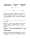
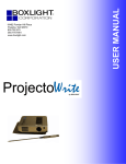
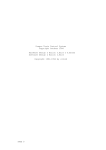
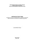
CSUS, ECS SENIOR DESIGN, MAY 2015 1 End of Project Documentation Jonathan Giacomelli, Jonathan Lloyd, Erik Metzner, Jeff Moffet, Anthony Phan Abstract—With an increase in technological growth, one major problem in education is the inability to keep up with the advancements that can benefit school systems. Not only could upgrading school systems save time and money in the long run, it could also increase learning capabilities of students as well. With younger children being exposed to more and more interactive technology each and every day, it would be wise to bring these familiar interactive methods into schools for use in educational purposes. The LightPen team has taken cost effective infrared based interactive whiteboard technology that integrates with other existing resources such as classroom installed projectors and computers, and made it more intuitive for those who are accustomed to traditional chalkboards or whiteboards to interact in an evolving technological environment. This document records the process of designing such a product over the course of two semesters. VIII-E VIII-F VIII-G VIII-H VIII-I VIII-J VIII-K VIII-L . . . . . . . . 6 6 6 6 6 6 6 6 IX Design Documentation IX-A Hardware . . . . . . . . . . . . . . . . . IX-A1 ATtiny84 . . . . . . . . . . . IX-A2 MCU 1 . . . . . . . . . . . . IX-A3 MCU 2 . . . . . . . . . . . . IX-B Software . . . . . . . . . . . . . . . . . IX-C Mechanical . . . . . . . . . . . . . . . . IX-C1 The Pen . . . . . . . . . . . IX-C2 Proximity Sensor Encasement 6 7 7 7 8 8 9 9 9 X Test Plan X-A Drawing Resolution Test X-B Concussive Drop Test . . X-C Communication Path Test X-D Proximity Sensor Test . . Keywords—interactive whiteboard, education, presentation, smartboard, digital whiteboard, eLearning, classroom technology, collaboration. C ONTENTS I Introduction 2 II Societal Problem 2 III Design Idea 3 IV Funding Proposals 3 V Project Work Breakdown Structure & Project Time Line 4 VI Risk Assessment VI-A Risk Mitigation by Severity Level . . . 4 4 VII Task Assignments 5 VIII User Manual VIII-A Introduction . . . . . VIII-B Contents . . . . . . . VIII-C System Requirements VIII-D Operating System . . . . . . . . . . . . . . . . . . . . . . . . . . . . . . . . . . . . . . . . . . 5 5 5 5 6 The contributors are students at the Department of Engineering and Computer Science, California State University Sacramento. J. Giacomelli is an accomplished Computer Engineer and will graduate in Spring 2015. J. Lloyd is studying Computer Engineering and will graduate in Spring 2015. E. Metzner is studying Computer Engineering and has two years of industry experience. J. Moffet is studying Computer Engineering and will graduate in Fall 2015. A. Phan is studying Electrical Engineering and will graduate in Fall 2015. Manuscript revised April 28, 2015. Setting Up Your LightPen . Setting Up Software . . . . Using Your LightPen . . . Keys and Functions . . . . Safety Precautions . . . . . Troubleshooting . . . . . . Technical Support . . . . . Regulatory Compliance . . . . . . . . . . . . . . . . . . . . . . . . . . . . . . . . . . . . . . . . . . . . . . . . . . . . . . 9 9 10 10 10 XI Integration Plans XI-A Dual Wiimotes . . . . . . . . . . . . . . XI-B Diffused IR Emitter . . . . . . . . . . . 11 11 11 XII Conclusion 11 . . . . . . . . . . . . . . . . . . . . . . . . . . . . References Appendix A: A-A A-B A-C 12 Acknowledgment Professor Dahlquist . . . . . . . . . . . Professor Rahimi . . . . . . . . . . . . ST Micro . . . . . . . . . . . . . . . . . 12 12 12 13 Appendix B: Important Data Sheets and Device Information 13 Appendix C: Team Member Resumes Biographies Jonathan Lloyd . . Jonathan Giacomelli Anthony Phan . . . Erik Metzner . . . . Jeff Moffet . . . . . . . . . . . . . . . . . . . . . . . . . . . . . . . . . . . . . . . . 13 . . . . . . . . . . . . . . . . . . . . . . . . . . . . . . . . . . . . . . . . . . . . . 19 19 19 19 19 19 CSUS, ECS SENIOR DESIGN, MAY 2015 I. I NTRODUCTION Every generation sees technology come and go through their classrooms, from chalkboards to whiteboard, to overhead projectors and PowerPoint lessons. This constant evolution of classroom tools are designed to make things much more easier and accessible, but some systems fail in that area, instead creating more problems. Every member of Team 8 has horror stories and success stories in their background, from teachers who best utilized the technology of the age, to those who terrorized students with archaic lesson plans. Each of us envisions a world benefited by a technology that helps the flow of ideas, from the instructor to the student in the most efficient and permanent manner. Through much brainstorming, the team set for the best way to tackle such a fundamental societal problem. How does one learn? How best can ideas be expressed? What technologies are available that augment human capacities in those regards? We came up with our compass, what was dubbed The Brainstorm Document, which in various forms is shown below. The LightPen IWB created by Team 8 has followed that course charted therein and will undoubtedly surpass the current state of technology used in education for the generation to come. II. S OCIETAL P ROBLEM We found in our research that the use of digital content in instructional settings is becoming more and more popular if not the only option in available materials in many instances. One of the difficulties in using digital resources is the ability to visually interact with them in real time. This loss of visual pedagogical methods such as writing on an overhead projection slide with a dry erase marker is often due to the use of digital content on a digital projector as teaching aids. While there are technologies available such as Interactive Whiteboards, these technologies are often not adopted due to limited budgets, limitations in implementation with existing resources, or difficulty in transitioning into a new workflow. A big problem in classrooms today is keeping up with technology that can help the classroom be more efficient with time and money. Another problem is the disadvantaged state visual learners are placed in when the use of digital resources lacks real time visual interaction. Its also worth while to point out how those who are presenting the material are often chained to a computer mouse and keyboard which can limit their interactive presence in the learning environment. Interruptions to an instructor’s teaching style such as these can actually drive them away from adopting such technology. For a long time now it has become clear that Information and Communication Technology, ICT, in learning environments is necessary for information processing, problem solving and utilizing visualization to be successful [1]. At least one study has shown that technical courses such as mathematics are greatly enhanced when smart technology is implemented in the classroom [2]. Even though the majority of instructors strive to communicate their understanding on a given topic, students do not always reach the potential of what is being taught. These gaps can be bridged by augmenting the instructor’s efforts 2 with applicable technology as opposed to previous pedagogical approaches [3], [4]. In fact, technologies that encourage interaction are shown to enhance student and teacher interaction [5] [6] [7]. In one study of undergraduate chemistry courses, it has even been shown to increase student activity. (see figure below) Fig. 1. Activity index, Science Direct Not all instructors are eager to change their teaching methods to accommodate technological advance. With this in mind it is important for new technologies and implementations to provide a path to help transition hesitant adopters to use the new technology [8]. In addition to educational value there are other perks to technology such as digital whiteboards. For example, dry erase marker supplies constantly need replenishing. After a while, the whiteboard becomes permanently stained and replacements will have to be acquired. Another important consideration is that existing technology in classrooms may vary widely so technological solutions would need to be versatile. From a cost effective point of view, integration with the existing technology would be beneficial such that the need for additional supporting technology would be limited. Also, much of the interactive technologies available are very expensive which limits availability to many educational institutions where budgets are limited. Simba Information published a report a couple of years ago on the different technology used for education, based on the number of hours used each day. The gathered data is depicted in the figure below. It is interesting to see that interactive whiteboards are used very often, which could possibly mean that students have grown accustomed to using this technology. More so for us, it is interesting to see that the two main ingredients for our system, projectors and desktop computers, are used respectively, 40% and 45% of the day. Integrating our system with the existing technology, projectors and desktop computers, may not be too much of a hassle. Technology can help a classroom setting be more interactive, by projecting whatever is on a computer onto the wall, and being able to write all over that image. This does not have to be confined to the classroom, but can also be visualized CSUS, ECS SENIOR DESIGN, MAY 2015 Fig. 2. Use of technology per day to teach ELL students, Academic Business Advisors [9] in a business setting as well. Business meetings can utilize this technology and make their Powerpoint presentations more interactive, as they never were before. Technology in learning environments that encourage interaction between instructors and students, and that provide visual interaction with presented materials are critical as other educational technologies move forward. These interactive technologies need to take account of the needs of instructors as well as limited budgets of schools. Those of us in Team 8 will tackle these shortcomings in our LightPen design, which brings us to the discussion of our design idea. III. D ESIGN I DEA We took our solution to create a better interface between the knowledgeable and those who seek knowledge and found the best way to summarize our idea was with this elevator pitch: The learning environment is strained by poor transmission of ideas from instructor to student; This can be improved using superior tools such as the following proposed digital whiteboard. Our idea is to create a pen, that fires an IR led when the user is writing, ie. when the pen is close to the board. The IR leds movements will be captured by the Pen Location System. Other information such as color changing and erasing can be transmitted by the pen to the Pen Location System as well. This information that is being transmitted by the pen will be relayed to the View. The View is a piece of software that writes when the user is writing, and changes color when the user wants to write in a different color, and so on. By moving traditional teaching methods towards digital means, this enables both teachers and students to be more interactive with class material and help foster educational improvements. We designed a featureset that best encompasses the flow from the instructor, through the technology, and to the student, which is listed below in our abridged punchlist: – The Pen will detect proximity to a flat surface • Outcome: The Pen will detect when it is close to a flat surface, and will detect when the Pen has moved away from the surface. 3 – The Pen will emit IR when close to a flat surface • Outcome: The Pen will be able to emit IR, given the successful detection of the previous feature. The Pen will not emit IR without the detection signal. – The Receiver will receive IR • Outcome: The Receiver will detect the IR signal and pass that data to the View. – Given the IR received, The Receiver/View will determine the X,Y coordinate of The Pen near the flat surface. • Outcome: When the Pen is close enough to the flat surface, the View will be able to determine where the Pen is on the flat surface. – The Receiver/View will change display on the flat surface, drawing lines • Outcome: The View will draw on the flat surface where the Pen is present. – The View will be able to have different colors and be able to erase • Outcome: The View will draw in the correct color, to include erasing. – The Pen will take user input to determine draw/color/erase state. • Outcome: The User will be able to change the color of what is written or be able to use erase mode, by only having to interact with the Pen in some way. We focused on the realizable physical phenomenon that will occur using our technology, so that we would have the most flexibility to solve such a complex problem and really plunge into the depths of all possible solutions. Using these, we matched each section within our brainstorm document, to produce a number of tasks. Each of us at Team 8 eagerly signed up for and tackled those tasks with vigor. With all of the excitement about our new project, it was easy to work on our new Lightpen, but paying for our new project didnt come as easy. IV. F UNDING P ROPOSALS When we decided to switch projects we talked briefly about how we would fund the project without Wijit’s help. I think we discussed each of us kicking in $70 maybe more or less. Anyway, Erik has been buying a lot on his own that I feel has been very useful toward the project, as well as donating a lot of his previously acquired items such as MCU/diodes etc. Each of us have pitched in here and there as well. I feel like we need to get a dialog going on budget, and what we expect/want to contribute. Then have a way to tag team purchases that we want to make. I feel like Erik is in a little deeper than he should be, and I’ve set aside a $20 emergency relief fund, cash, in my wallet for the next time I see him. After we all get a chance to talk about funding a little more I’m willing to send a little more his way if needed. At any rate I plan to be more involved in future purchases. Before we even had all of the funding details figured out, we were going full speed ahead into the work breakdown structure and project timeline. CSUS, ECS SENIOR DESIGN, MAY 2015 4 V. P ROJECT W ORK B REAKDOWN S TRUCTURE & P ROJECT T IME L INE Below is our infamous Gantt Chart. This details each of the tasks in the brainstorm document and attaches both a Resource (aka a member of Team 8) and a timeframe to ensure all features are being given their due processing. Fig. 4. Fig. 3. Project Work Breakdown Structure & Project Timeline The details of the Gantt Chart will be fully displayed in the Task Assignments section of this document. We have met numerous times and had lengthy discussions to ensure all teammates are on the same page and have a clear understanding of each member’s ideas. We have instituted a number of skilled communication techniques to expedite and parallelize these discussions, and we were able to produce a well formed document that describes all known tasks. Some tasks are not known, either because the precluding research tasks are still in progress, or because they depend on other tasks and modules to be complete before the research can begin in earnest. Either way, these unknowns have also been described below to ensure that they are recognized and properly addressed when the time comes, and so that no evolution or process gets lost in the cracks. Below is a simplified chart of our work breakdown structure. Each feature is divided into six steps. First research, then procure necessary parts, breadboard, PCB, software coding, and finally integrating each component into the final product. Each step was divided among our team members, based on their interests and skill set. Even with all of the skills that we, as a team, possess, Murphys Law and several other issues still exist that could hamper the progress of our project; Thus, we must evaluate the risks. VI. R ISK A SSESSMENT Considering risk was part of our planning early on in the project, especially when planning the Work Breakdown Structure (WBS). The team generally had a good handle on individual priorities and dealing with the associated risks. One of the big priorities for some team members were family life as they were expecting children. Involvement from these team Work Breakdown Structure members in the WBS was minimized during the time directly after their new children would arrive. Everyone had the task of balancing this project with other projects, class work, and exams. Part of mitigating these risks was creating a Google Calendar which integrated detailed individual schedules and availabilities. This made it possible to make the best scheduling decisions, especially if they needed to be made quickly. The team needed to anticipate risks such as equipment being lost, or a crucial project component being damaged. Perhaps we could experience a problem with software tools after it is updated. All of these were considered when determining the priority of tasks, and subtasks such as ordering parts. More critical tasks were scheduled early so that if there were any emergencies there would be time to take corrective action. Also, emphasis on ordering parts early before they were needed was made to reduce wait time as much as possible. Another critical point was to order extra parts. A. Risk Mitigation by Severity Level ◦ Green: • Work, other school related demands ◦ Team member schedule on Google Calendar gives visibility of potential time demand conflicts so that tasks are prioritized to reduce conflicts •One team member is given a task instead of another team member because the other team member has heavy time demands that would limit the amount of time they would have to work on the task causing delays. • Sick or injured team member ◦ Team members keep in communication about what they are doing, and if they need help completing a task. ◦ Yellow: • Equipment breaking/lost ◦ Have extra tools on hand. • Senior Design assignments ◦ Order parts early so that they are in transit while we are working on documentation assignments. ◦ Red: • Part lost/broken/inadequate CSUS, ECS SENIOR DESIGN, MAY 2015 • • • • ◦ Have extra parts on hand ◦ Do small test cases, and have backup plans •Build small breadboard proofs of features before integrating them into the complete system. Technical difficulties ◦ Make sure there is time planned for setting up tools such as IDEs etc. Insufficient Funds ◦ Budget ◦ Factor in time to fabricate parts such as the enclosure from existing resources such as pens and markers. Physical system damage/accident ◦ Have extra parts on hand ◦ Take a modular approach such that integration of features into a complete system do not use the parts from the breadboard proof which can be used as a backup. Family emergencies ◦ Plan for team members that are expecting children to be less involved when the time comes. ◦ Plan for more than one team member to be involved in any given task for redundancy. 5 • Fig. 6. For such tasks as documentation, we were equipped with extra experience the second time around, to the point that we were able to be much more productive in a short amount of time. Task and Team Member Hours Distribution Table With this understanding tasks have been summarized by feature for easier reading and now we come to the User Manual for more specific information about our project. Fig. 5. Risk Assessment Chart Now that we have a better understanding of the many risks that are involved in completing this project in a timely manner, we will exercise more diligence in how we assign the multitude of tasks that are required for this project. VII. TASK A SSIGNMENTS The hours spent on tasks are shown in the Task and Team Member Hours Distribution Table. The hours reported here bring attention to the point that we did change projects in week eight which causes our hours to be less than would be expected. However, the following considerations should be made: • Many of the efforts that we had put toward the previous project were transferable, such as research for MCU selection. VIII. U SER M ANUAL A. Introduction Thank you for using the LightPen as part of your Infrared(IR) based Interactive Whiteboard(IWB) solution. The LightPen is designed to IR IWB usage intuitive for those accustomed to traditional whiteboard, and additionally offer features that take advantage of what IWBs have to offer. B. Contents • LightPen • User Guide • (Optional) USB Receiver C. System Requirements Hardware • Wiimote (or other IR Positioning Human Interfacing Device) connected to PC • USB port for optional USB Receiver Software • gtkWhiteboard • Ardesia CSUS, ECS SENIOR DESIGN, MAY 2015 D. Operating System Linux E. Setting Up Your LightPen Carefully open the battery compartment, remove the battery holder, and insert batteries into the battery holder while following the positive and negative battery symbols. Insert the battery holder in the direction the arrow points on the battery holder. F. Setting Up Software Obtain a copy of gtkwhiteboard and follow their instructions for installing it on the computer you will be using the LightPen to interact with: http://www.stepd.ca/gtkwhiteboard/ Also, install the overlay software Ardesia found here: https://code.google.com/p/ardesia/ G. Using Your LightPen First, the LightPen activates when the writing tip is within a certain distance to the screen. This distance can be slightly customized by putting the tip near the screen and pressing the calibrate button on the LightPen when youre comfortable with the distance. Always make sure that the Wiimote has a clear view of the writing tip of the LightPen when you expect it to be active. Now, lets proceed. Make sure the LightPen is calibrated to activate when desired. Position the Wiimote so that it has a clear view of video display where the LightPen will be used. Launch gtkwhiteboard. Press 1 & 2 button on Wiimote, then click Start in gtkwhiteboard to begin the calibration. Activate the LightPen at the four corners of the screen, as directed by gtkwhiteboard. Once successful calibration is complete, the LightPen will be ready for use in Ardesia. Launch Ardesia and begin using the LightPen. 6 1 Laser Button 2 Calibrate Button Turns pointing laser on and off. With the LightPen near the writing surface this button sets the current position as the distance to the surface when the LightPen should activate. 3 Next Button (Optional with USB Receiver and software) 4 Back Button (Optional with USB Receiver and software) 5 Communication Light 6 Laser Pointer Laser beam is goes in the direction of the arrow. DO NOT LOOK DIRECTLY AT THE LASER BEAM 7 Writing Tip The LightPen’s writing tip needs to be visible by the Wiimote or similar device while attempting to write with the LightPen 8 Color Change (Optional with USB Receiver and software) Changes the color of the line TABLE I. This part of the pen needs to be visible to the Wiimote or similar device when attempting to write with the LightPen K EY F EATURES E XPLANATION I. Safety Precautions • Make sure you always have a firm hold on the LightPen. • Never point the laser at a person or pet. Do not look at the laser directly or with any optics like binoculars or a magnifying glass. • Keep the LightPen out of reach of children. • Do not attempt to repair or alter the LightPen. J. Troubleshooting I’m not able to write on the screen, or the writing is intermittent. . . Make sure of the following: • The yellow light flashes once when the LightPens writing tip is close to the screen. • The batteries are fully charged. • The calibration button on the LightPen has been pressed with the writing tip of the LightPen close to the screen. • There is nothing blocking the Wiimotes view of the writing tip of the pen at any time. • The Ardesia overlay software is running, the Wiimote has been connected to the computer and has been calibrated. K. Technical Support Email: [email protected] H. Keys and Functions L. Regulatory Compliance This device complies with Part 15 of the FCC Rules. Operation is subject to the following two conditions: (1) This device may not cause harmful interference, and (2) This device must accept any interference received, including interference that may cause undesired operation. IX. Fig. 7. Key Feature Map D ESIGN D OCUMENTATION The design documentation consists of the system hardware and software . Block diagrams, hardware and software descriptions will be discussed. CSUS, ECS SENIOR DESIGN, MAY 2015 7 Fig. 8. LASER RADIATION–DO NOT STARE INTO BEAM OR VIEW DIRECTLY WITH OPTICAL INSTRUMENTS CLASS II LASER PRODUCT Fig. 9. MCU 1 A. Hardware For clearer purposes of describing the hardware design, a block diagram will be used. There are two block diagrams due to using two separate microcontrollers. The use of two microcontrollers were chosen due to the number of useable pins (12 pins). MCU1, figure 9, controls the front end components of the pen, and MCU2, figure 10, controls the back end components of the pen. MCU1 • Laser Diode: A common red laser pointer. • Proximity Sensor: A sensor to detect when the pen is near the board to allow the user to write. Once in proximity, the MCU will turn on the IR LED. • Indication LED: A yellow LED to indicate to the user that the pen is in proximity and can begin writing. . . . • IR Output: An IR LED that will be turned on for the Wiimote to track. MCU2 • Radio: Communication between the pen and computer, mainly for color changing purposes. • Rotary Encoder: User input device to change between colors. • RGB LED: RGB diode for user to see which color has been selected. 1) ATtiny84: The chosen microcontroller for the system is an ATtiny84 and seemed the right choice due to its size and achievable speed. It could easily be soldered onto a pcb and fit into the pen without taking too much room. The ATtiny84 has built in ADCs which has a resolution of 5 volts mapped to 1024 units and can be ran up to 20 Mhz [10], well above our range of desired speed. One ADC pin (pin 9) was used for MCU1 and the other useable pins were used as either strictly digital output pins or analog output (PWM) pins. A pinout of of the ATtiny84 is depicted in figure 11. 2) MCU 1: As stated before, MCU1 controls the components at the front end of the pen. This consists of the proximity sensor, red laser pointer and an indicator LED as shown in figure 12. Fig. 10. MCU 2 Fig. 11. ATtiny84 pinout [10] Red laser pointer - The laser pointer is a common tool that teachers use to catch students attention. As such, it seemed appropriate to add it into the system. This is not tied in with the MCU, but is controlled by a simple push button switch. The Laser pointer is labeled LaserDiode1 in figure 12. Indicator LED - The indicator led is a visual cue for the user that they are close enough to the surface to begin writing. When the user holds the pen up close to a surface, the LED indicator will turn on for a second and then turn off, letting them know that the pen is activated for writing. The LED used is the TLCs5101, a 5mm yellow LED. The indicator is labeled LED3 in figure 12. Proximity Sensor - The proximity sensor will detect when the pen is held close to the surface. It is designed by having CSUS, ECS SENIOR DESIGN, MAY 2015 one LED forward biased, and the other reversed biased. The forward biased LED has its anode connected to the MCU, and will be sending constant pulses through pulse width modulation. This is pulsing LED is labeled LED1 in figure 12. The second LED, labeled LED2, has its cathode connected to the supply rail. When it sees the pulses from LED1, a voltage will be created at LED2s anode. This output voltage is connected to the ADC (pin 9) of the MCU as seen in the MCU1 circuit. IR LED - The IR LED will output the infrared light that the Wiimote will catch and follow as the user is writing about the surface. The IR LED used was the TSAL4400, a 3mm IR LED. This IR LED has a maximum forward current of 100 mA [11], well above what the MCU can output. To overcome this, a switching MOSFET was used with the gate being controlled by the MCU. The IR LED is labeled IrED1 in the MCU1 Circuit. Fig. 12. 8 Fig. 13. MCU1 circuit Fig. 14. Software Relational Diagram MCU1 circuit 3) MCU 2: MCU2 controls the components at the front end of the pen. This consists of the rotary encoder, RGB LED, and the radio as shown in figure 13. Rotary Encoder - The rotary encoder acts as a user input device to change the color the user is writing in. The rotary encoder is mapped for eight different colors, red, orange, yellow, green, blue, purple, white, and black. Earlier stages of the pen utilized a potentiometer, but was replaced by the rotary encoder, due to its ability to swing full 360 degrees without having to backtrack to zero. The rotary encoder is labeled RotEncoder in figure 13. RGB LED - The RGB LED is a four pin common cathode LED, labeled LED4 in figure 13. Its purpose is to give the user visual cues of what color they have chosen. In order to change colors of the LED correctly, the RGB pins had to be connected to the designated PWM pins of the MCU. Radio - The radio takes the input from the rotary encoder and communicates that information to the Ardesia software. The radio takes the most pins of MCU2 (pins 6-10), and is labeled Radio Reserved 1-5. B. Software As the User interacts with the LightPen hardware, code running on the embedded microcontroller sends data via serial bus to an embedded radio. A second radio is paired to the one in the PEn and is attached the the PC, which uses an API to convert that received USB data from the radio into hotkey presses. Shown below is where the driver software currently finds the double click state in touchpad mode, changing the signals sent from simple mouse position, to a left-click held down plus the mouse’s position used to draw in the overlay software. Fig. 15. Double-Click code override section We send those Hotkeys to the overlay software through the existing OS of the PC. Since both driver and overlay softwares are Open Source and Multiplatform, this should be useable by all OSs. We are currently developing in Ubuntu 14.04, with testing occurring simultaneously in Windows 7. We extended the overlay software to receive the Hotkeys we choose, and CSUS, ECS SENIOR DESIGN, MAY 2015 purposefully chose extremely non-standard combinations to prevent clashing with other major software suites. 9 Each PCB in the pen has a custom 3D printed capsule, figure19, to protect its circuit from outside damage due from dropping, dust, etc. Each capsule has slots for wire connections. C. Mechanical The mechanical component of the system consisted of the physical encasement of the pen. Through many iterations, the final pen is now built using pvc pipe and custom 3D printed pieces for the end caps and a tray for buttons to be mounted, as well as holders for each PCB. 1) The Pen: The pen body is created from a inch diameter pvc pipe purchasable from a local hardware store. The length of the pipe is 9 inches long. A portion of the pvc pipe was cut out and a 3D printed piece was created to be mounted in the cut out portion. This 3D printed piece was designed to easily mount the buttons on a flat surface, rather than a curved surface. This can be seen in figure 16. Fig. 16. Button tray with and without cover Two other printed pieces were created for the front end and back end of the pipe. The front end, figure 17,houses the proximity sensor, the laser diode, IR LED, and an indicator LED. The back end printed piece, figure 18, houses the rotary encoder and RGB LED. Fig. 17. Fig. 18. Pen front end Pen back end Fig. 19. Pen back end 2) Proximity Sensor Encasement: The front end of the pen houses the proximity sensor, a major feature of the project. Multiple prints were designed for testing the various angles between the two LEDs to find a satisfactory angle. Finding the correct angle between the two LEDs to detect the right distance for the user to begin writing is very important. If the angle between the two were too large, the LED would reflect back into the other at a closer distance such as figure 20a. The IR LED may not turn on at all for the pen could possibly obstruct reflection back into the proximity sensor. If it were too small, such as figure 20b, the LED would reflect back into the other at a farther distance which would turn on the IR LED at a farther distance. An optimal angle would be one that does not detect at a large distance, but also not too close, such as figure 20c. Through testing and multiple 3D printed pieces to hold the two LEDs at specific angles, it was found that 10 degrees between the two were optimal for our case. Fig. 20. Proximity sensor angles X. T EST P LAN To ensure a working product, the product should be put under as many relevant tests as possible. Having a test plan for a product is highly important, not only to see if it is functional, but to see if it performs consistently in many settings and situations. Tested factors included, but were not limited to, the Wiimotes position as it pertains to angle and occlusion, the Wiimotes effect on display quality in terms of its distance from the screen, and light interference on the proximity sensor of the pen. A. Drawing Resolution Test The purpose of this test was to maximise the hardware and software related to drawing such that The Pen draws into the screen as close to the performance of a real whiteboard pen ( inch resolution) on a surface approximately as large as a regular whiteboard surface (4ft tall x 8ft wide). The resolution is restricted to the Wiimotes IR camera. In some cases, maybe to due to a faulty Wiimote, or perhaps a counterfeit one, drawing straight lines ended up being jagged and pixilated CSUS, ECS SENIOR DESIGN, MAY 2015 10 Test 1 Front End Cap Back end cap Button Cover Functionality Run # Vertical Horizontal Test 2 secure secure Front End Cap Secure Secure Back end cap Seperated Seperated Button Cover Functional Functional Functionality Vertical Horizontal Test 3 secure secure Front End Cap Secure Secure Back end cap Seperated Seperated Button Cover Functional Functional Functionality Vertical Horizontal secure secure Secure Secure Seperated Seperated Functional Functional 030915-01 030915-02 030915-03 030915-04 030915-05 030915-06 030915-07 030915-08 030915-09 TABLE III. D ROP TEST RESULTS as seen in figure 21. This test was carried out by attempting to draw the smallest square possible on the screen. The goal of this test was to drive the area of the square so low that it is comparable to a whiteboard marker, and is equally difficult to measure. If the square is too small to measure using a common ruler, then the requirement is met. Otherwise, the area of the smallest possible drawn square was logged. These squares are also depicted in figure 21. Pen Angle Occlusion Pass/Fail 30 30 30 45 45 45 60 60 60 Full Partial None Full Partial None Full Partial None Fail Fail Pass Fail Fail Pass Fail Fail Pass TABLE IV. P EN ANGLE AND OCCLUSION RESULTS C. Communication Path Test The purpose of this test was to ensure that the Pen and the PC running the overlay software can communicate, meaning that the Wiimote does in fact see the IR LED emitting from the pen. The procedure was simple, the software and Wiimote were set up and drawing was attempted. If the Wiimote detects the IR LED and the able to draw in the software, this resulted in a pass. The test results showed that the the software functions correctly and the Wiimote does in fact detect the IR LED. D. Proximity Sensor Test Fig. 21. Jagged lines due to poor resolution During this test it was found that the resolution was approximately the same as tests before in the previous semester. After troubleshooting, it was found that if the IR LED was aimed directly back towards the wiimote, instead of reflecting off the surface, the resolution became far better, as shown in the test result in table II. After some investigation, it was found that the IR LED was drawing approximate 30mA, which is much less than the anticipated 100mA. It was concluded that the IR LED was not emitting at full brightness and has been causing problems for the IR camera in the wiimote to detect. By running the IR LED at its maximum forward current, better results were observed in terms of resolution. B. Concussive Drop Test The concussive drop test examined the physical durability of our product. The pen was held a meter high above the floor and dropped onto the ground both in a vertical position and horizontal position. The use of 3D printed pieces to hold all the components resulted in a much more durable product. The test was ran three times and through each one, both the front and back end caps were intact. The button cover was separated from the tray after each test. Results are displayed in table III. This test examined the different factors and elements that the proximity sensor would be subjected to. Factors included were the material that the LEDs would be reflecting off of, the angle between the two LEDs and the ambient light in the room. The angle between the two LEDs were tested at 6, 8, and 10 degrees. Using the 10 degree angle between the two, the proximity sensor produced a maximum of roughly 1.2V. This maximum signal occurred at about an inch away from a flat surface. The 6 and 8 degree test produced a 1V maximum at a closer distance. For practicality the 10 degree angle was chosen because the front end of the pen where the proximity sensor lays could possibly obstruct the proximity sensor from detecting a surface at all and also produced a much higher signal. Another test was ran to see at what angle the user holds the pen to the surface. This is to mimic the size of a whiteboard, where users will have to hold the marker high above there head and possibly at an acute angle. This is to take account that the user will not be holding the pen perpendicular to the surface at all times. Using the 10 degree angle between the two LEDs, it was found that the user can hold the pen to at least 60 degrees to the surface. Any higher than that, and depending on the material of the surface, the proximity sensor can have trouble detecting closeness. Occlusion was accounted for and it was found that the Wiimote needs a direct line of sight of the IR LED in order to detect the infrared light. Results are depicted in table IV. The material that the user writes on plays a big factor on the proximity sensors ability to reflect its light back into itself. If the user writes on a glossy material such as a computer screen, the light does not reflect back very well and the proximity sensor did not produce usable signal very well. This test was done on a laptop screen. Materials that do not absorb light are CSUS, ECS SENIOR DESIGN, MAY 2015 Run # 030915-01 030915-02 11 Screen Size (in x in) Wiimote Distance (in) Wiimote Angle (deg) Lighting Hand Resolution (area in2̂) 117x66 117x66 166 166 82 82 fluorescent fluorescent right right 10.5 1.44 TABLE II. D RAWING RESOLUION TEST RESULTS Rating (1 least optimal, 5 most optimal) Material Glossy Screen (laptop, tv, etc...) Matte Screen (laptop, tv, etc) Canvas Screen White painted wall TABLE V. 3 4 5 5 S URFACE MATERIAL RESULTS much better for our product. Testing on the pull down screen at the front of the senior design room worked very well. The light was able to reflect back and there were no problems with detecting closeness to the screen. Table V depicts results for surface material. The ambient light in the room also plays another factor for our proximity sensor. In the MCU code, the threshold for sensing proximity at the highest to remove ambient light. This means that light from the proximity sensor can only activate itself. However, if the proximity sensor is pointed directly at light source, it has a tendency to think that it is detecting proximity. This test was ran in both darkened and fully lit rooms and was successful through both. B. Diffused IR Emitter Another course of testing found that using a diffused IR source for the Wiimotes to track created more consistency. This is because alternative methods such as tracking the light from the emitter shining on the display may be inconsistent depending on the reflectivity of the surface. A reflective surface can cause the IR light to bleed outwards on the surface and cause confusion to what the Wiimote is seeing. As concluded in table V, a less reflective surface is the most optimal. The IR light does not bleed out as much and is kept in a finer circle on the surface. One solution to create diffused IR emission would be to create a small window of infrared light onto the pen, so that it could be seen from any angle and position, as shown in figure 23. Fig. 23. XI. I NTEGRATION P LANS This section considers possible solutions to problems that were found during testing. A. Dual Wiimotes Testing showed that there was a problem with resolution on larger displays. This lead us to find that the Wiimotes are actually rather low resolution. One potential solution we found was HID driver software for the Wiimotes that allows two Wiimotes divide the display which effectively increases the resolution as shown in figure 22. By having two Wiimotes, a finer resolution can be obtained, as well as the user not having to deal with being in the line of sight between the Wiimote and the IR LED. Fig. 22. Dual Wiimote concept IR window concept XII. C ONCLUSION Through two semesters and a ton of hours put into this project, we are confident to say we have a system that can compete with current implementations of digital whiteboards and allow the instructor and the student to communicate far more effectively than previous technologies have allowed. Each member of Team 8 has shown the desire and capability to take this technology from its current state, into a more full and realized version by the end of the year. Each generation sees this a change in technology, and our LightPen IWB is at the forefront of the next generation of technologies that empower learning! CSUS, ECS SENIOR DESIGN, MAY 2015 I III IV II V 1 2 3 4 5 6 7 8 9 10 11 12 13 14 15 16 17 18 19 20 21 22 23 L IST OF TABLES Key Features Explanation . . . . Drop test results . . . . . . . . . Pen angle and occlusion results . Drawing resoluion test results . Surface material results . . . . . 12 [8] . . . . . . . . . . . . . . . . . . . . . . . . . . . . . . . . . . . . . . . . . . . . . L IST OF F IGURES Activity index, Science Direct . . . . . . . . . . Use of technology per day to teach ELL students, Academic Business Advisors [9] . . . . . . . . Project Work Breakdown Structure & Project Timeline . . . . . . . . . . . . . . . . . . . . . . Work Breakdown Structure . . . . . . . . . . . . Risk Assessment Chart . . . . . . . . . . . . . . Task and Team Member Hours Distribution Table Key Feature Map . . . . . . . . . . . . . . . . . LASER RADIATION–DO NOT STARE INTO BEAM OR VIEW DIRECTLY WITH OPTICAL INSTRUMENTS CLASS II LASER PRODUCT . . . . . . . . . . MCU 1 . . . . . . . . . . . . . . . . . . . . . . . MCU 2 . . . . . . . . . . . . . . . . . . . . . . . ATtiny84 pinout [10] . . . . . . . . . . . . . . . MCU1 circuit . . . . . . . . . . . . . . . . . . . MCU1 circuit . . . . . . . . . . . . . . . . . . . Software Relational Diagram . . . . . . . . . . . Double-Click code override section . . . . . . . Button tray with and without cover . . . . . . . . Pen front end . . . . . . . . . . . . . . . . . . . Pen back end . . . . . . . . . . . . . . . . . . . Pen back end . . . . . . . . . . . . . . . . . . . Proximity sensor angles . . . . . . . . . . . . . . Jagged lines due to poor resolution . . . . . . . . Dual Wiimote concept . . . . . . . . . . . . . . . IR window concept . . . . . . . . . . . . . . . . 6 10 10 11 11 2 3 4 4 5 5 6 7 7 7 7 8 8 8 8 9 9 9 9 9 10 11 11 R EFERENCES [1] [2] [3] [4] [5] [6] [7] Barak, M. (2007). Transition from traditional to ICT-enhanced learning environments in undergraduate chemistry courses. Computers & Education, 48, 30-43 A. C. Edmondson and I. M. Nembhard ”Product development and learning in project teams: the challenges are the benefits” Journal of Product Innovation Management, vol. 26, pp. 123-138, 2009 J. V. Chen, D. C. Yen and K. Chen ”The acceptance and diffusion of the innovative smart phone use: A case study of a delivery service company in logistics” Information & Management, vol. 46, pp. 241-248, 2009 B. Han and V. R. Prybutok ”’I guess’ to ’I get’: an effective use of smart technology to transform undergraduate statistics education” International Journal of Information and Operations Management Education, vol. 5, pp. 78-85, 2012 M. Pero, N. Abdelkafi, A. Sianesi and T. Blecker ”A framework for the alignment of new product development and supply chains” Supply Chain Management: An International Journal, vol. 15, pp. 115-128, 2010 D. Blanchard ”Supply chain management best practices” 2010, John Wiley & Sons, USA J. Yue, Y. Xia and T. Tran, ”Selecting sourcing partners for a make-toorder supply chain” Omega, vol. 38, pp. 136-144, 2010 Al-Qirim, N.; Mesmari, A.; Mazroeei, K.; Khatri, S.; Kaabi, Z., ”Developing teaching scenarios in the classroom using interactive smart board ecosystem,” Digital Ecosystems and Technologies (DEST), 2010 4th IEEE International Conference on , vol., no., pp.525,530, 13-16 April 2010 [9] Mitch Weisburgh, ”Research on ELL Students and on Technology Adoption” Academic Business Advisors, April 2012 [10] Atmel, ”8-bit Microcontroller with 2/4/8k Bytes In-System Programmable Flash”, ATtiny84 datasheet, 2010 [11] Vishay, ”High Power Infrared Emitting Diode”, TSAL4400 datasheet, 2014 A PPENDIX A ACKNOWLEDGMENT A. Professor Dahlquist Professor Dahlquist provided valuable guidance and counsel as our Project Advisor during the first term of the project. He expressed interest in our project, gave constructive feedback and criticism, and provided possible ideas for solutions that we could further explore. Furthermore, He made sacrifices to meet with our team outside of assigned lab schedule due to our teams scheduling conflicts. We are also very grateful for his support while our team switched projects Professor Dahlquist, We would like to thank you for your critical role in our project as our Faculty Advisor. We cannot express how valuable your motivative influence, guidance, and counsel have been to the success weve had so far with this project, and also in our academic careers. We are especially grateful for your support when we decided to switch this project, AKA Plan B. We are very aware that we would not have been able to successfully switch without your support. The switch has generated untold amounts of project motivation and excitement. Best Regards, Team 8: Light Pen Jonathan Lloyd, Jonathan Giacomelli, Anthony Phan, Erik Metzner B. Professor Rahimi Professor Rahimi was our Faculty Adviser during the second semester of the project. He usually gave us a prospective that we had not considered before which often lead to better results. Though he may not have known, his positive attitude took us from low moral before a meeting to feeling up beat about how things were going afterward. Without further adieu: Professor Rahimi, Thank you so much for exceeding your role as Faculty Adviser. The unstructured moments where you offered advise from your life experience thus far are rarely had in a class room. We especially appreciate what you shared with us in regards to preparing for and presenting to an audience. We appreciate that you transitioned into your role as our adviser while we were half way through the project, and seamlessly CSUS, ECS SENIOR DESIGN, MAY 2015 offered assistance when we needed it at a level that one would imagine you had been our adviser from the beginning. Best Regards, Team 8: Light Pen Jonathan Lloyd, Jonathan Giacomelli, Jeff Moffet, Anthony Phan, Erik Metzner C. ST Micro ST Micro has graciously given us samples of their photon proximity sensor. Their commitment to education and innovation goes far beyond what one might expect. ST Micro Samples Program Administrator, We would like to express our gratitude for sending us samples of your Time of Flight proximity sensor: VL6180X Proximity sensor Your faith in our educational experience and emerging abilities has left impressions that have not only fostered a good industry relationship, but have also influenced our view of industry and working together for a good cause. Best Regards, Senior Design Team 8: Light Pen California State University Sacramento: Computer Engineering Department Jonathan Lloyd, Jonathan Giacomelli, Anthony Phan, Erik Metzner A PPENDIX B I MPORTANT DATA S HEETS AND D EVICE I NFORMATION ATtiny84 Datasheet [10] 13 A PPENDIX C T EAM M EMBER R ESUMES CSUS, ECS SENIOR DESIGN, MAY 2015 14 Jonathan Lloyd OBJECTIVE Obtain a computer engineering position in embedded system development with possible leadership opportunities. EDUCATION B.S. DEGREE ▪ Computer Engineering ▪ California State University Sacramento Spring 2015 A.A. DEGREE ▪ Social Science ▪ American River College, Sacramento 2014 A.A. DEGREE ▪ Language Studies ▪ American River College, Sacramento 2012 • Awarded Osher Scholars, and Fanselau Computer Science Scholarships. • Maintained a 3.59 GPA while taking upwards of 15 units per semester and working 20hrs per week. PROJECTS AND ACTIVITIES • Wrote a robust C program utilizing multiprocessing and socket programming with a double pumping scheme. • Senior Design Project – Light pen for use with IR based digital whiteboards. ◦ Integrated 2.4GHz radio communication on a shared SPI bus with a USB interface and firmware. ◦ Promoted a photon proximity sensor and developed a rapid prototype using its I2C interface. ◦ Exemplified by instructors for engaging the audience during presentations. • Designed a MIPS based RISC ASIC processor with a seven stage pipeline, and other advanced features. • Developed an OS in C/Assembly in a team of two in Linux using vi, gcc, make, gdb, Git, and Doxygen. RELATED COURSES • Adv. Computer Organization • Computer Hardware Design • Computer Nwk and Internet • PCB Design Fundamentals • • • • Data Structures and Algorithms DB Web Apps PHP/MySQL Operating System Pragmatics Obj Orient Prog in C++ • • • • System Level Prog in C Intermediate Network Tech Group Communication Small Business Mgmt PROFESSIONAL EXPERIENCE COMPUTER/SOFTWARE ENGINEER 2013 – Present Echelon Corp... San Jose, California; and Lumewave Inc. which was acquired by Echelon Corp. • Selected to lead project to overhaul hardware and software implementation of the control management system. • Implemented and managed Git source control with a work flow adapted to accommodate the existing team needs. • Integrated a Google Maps Javascript API solution into VB.net based control management software to dynamically display outdoor lighting control node geo-locations and detailed status information stored in a SQLite DB. • Wrote proof of concept message relay program in C which contributed to the migration to a Linux based solution. • Updated production firmware written in assembly to add functionality or accommodate hardware changes. • Took the lead in maintaining factory production software, providing support, and training international associates. • Trained technician to use a sophisticated voltage source, DMM, and custom equipment. • Significantly involved in engineering solutions to expand current product offering capabilities. • In-depth experience with SQLite optimization involving transaction queuing, and sophisticated queries. AREA SUPERVISOR 2006 – 2008 L.D.S Church... Caribbean Islands • Promoted to Team Leader, then District Leader, supervising 4-6 area representatives. • Developed strong Spanish reading and writing skills with significant on-site experience including translation. DATA CONTROLLER 2005 – 2006 FDI Collateral Management (now known as Dealer Track)... Sacramento, California • Designed a program in C# .NET and MS SQL to log process execution statistics on production servers. • Completed assignments ahead of schedule by programming scripts to automate tasks. CUSTOMER SERVICE ASSOCIATE 2004 – 2005 Sears Home Central... Sacramento, California • Dramatically increased daily printing efficiency of over 300 service orders by programming scripts. • • OTHER ACHIEVEMENTS AND EXPERIENCE Attained the Eagle Scout award in the Boy Scouts of America program, and served in leadership positions. Received an award for best leadership skills out of more than 20 participants in a leader training program. CSUS, ECS SENIOR DESIGN, MAY 2015 15 CSUS, ECS SENIOR DESIGN, MAY 2015 16 CSUS, ECS SENIOR DESIGN, MAY 2015 17 CSUS, ECS SENIOR DESIGN, MAY 2015 18 ERIK R. METZNER erik.r.metzner [at] gmail {dot} com Professional Objective: Obtain a position at a major computer systems engineering firm. Long-term: System architecture, artificial intelligence, OS development. EDUCATION Computer Engineering B.S. – CSU Sacramento – Senior, Graduating December 2015 Physical Science/Mathematics A.S. – American River College – December 2011, GPA: 3.2 WORK EXPERIENCE Software Engineering Intern, VeriFone, Rocklin, California. (May 2014 – August 2014) • • Designed an energy efficiency and software optimization project for portable point-of-sale terminals. Collaborated with hardware engineers to resolve existing embedded OS bugs and hardware faults. Architecture R&D Intern, Micron Technology, Folsom, California. (May 2012 – September 2013) • • • Created the HydraDrive system for SQA: Automated massive-multiboot server drive deployment. Provided infrastructure support for automated Jenkins regression testing of the enterprise SSD product line. Maintained and redeployed over one hundred SQA servers through multiple product expansions. Engineering Contractor, Intel, Folsom, California. (2008) • • Liaised with developers on graphics driver and firmware SQA for chipset-level graphics. Conducted competitive graphics hardware performance analysis of nVidia & AMD product lines. Owner, Performance Computing, Carmichael, California. (1999 – 2007) • • • Developed custom computer systems for professionals, with emphasis on OS performance optimization. Applied OS-hardening, IO optimization, extensive overclocking, and custom cooling-system design. Perfected OS-minimization: The extreme surgical reduction of bloated OS subsystems. TECHNICAL EXPERIENCE Development: C, C++, Python, Perl, Bash, Verilog, VHDL, MATLAB, x86-assembly, Linux IPC, debugging, concurrency, OO paradigms, source control, UML, the SDLC, Agile development, ADTs, CMOS layout, OpenSource RTOS, and JIRA / Confluence. System Expertise: Linux & Windows optimization, hardware virtualization, Microsoft Sysprep, GRUB, SYSLINUX, MD-RAID, OS-minimization & hardening, and system stability testing. Hardware Related: I2C, SPI, CAN, FPGAs & microcontrollers, PCB design & construction, electrical schematics, datasheets, thermal resistance, electronics packaging, soldering, battery chemistry / recharging, logic analyzers, oscilloscopes, DMMs, signal generators, extensive PC system-building & overclocking, custom PC cooling-system design. Familiar with (and own) over one thousand analog-glue and IC components from various manufacturers. Limited 3D CAD, 3D Printing, NI LabVIEW, and MySQL experience. Senior Project: Projector-based digital whiteboard. Hobby Projects: Pseudo A.I. personal assistant, 24-core parallel processing microcontroller network, performance-optimized custom android ROM, Linux kernel minimization, software-defined radio, and homemade acrylic vacuum forming. Other Notables: Nine years experience in Boy Scouts of America (Order of the Arrow). Lifelong experience with local community service. Five years experience in metalworking; lathe, machining, forging, casting, welding. Top 1% in state-wide mathematics and physical science testing as a youth. CSUS, ECS SENIOR DESIGN, MAY 2015 Jonathan Lloyd Currently studying at California State University Sacramento. J. Lloyd will complete a B.S. in Computer Engineering in Spring 2015. While going to school J. Lloyd also works for Echelon. During J. Lloyds time with Echelon/Lumewave he has been involved in the development of microwave motion sensor, production test software for lighting control modules, commercial system management software for lighting control modules, and other endeavors. In 2014 J. Lloyd was a key player in modifying the lighting control module firmware to accommodate new components that required changes in operational timing. Jonathan Giacomelli I have been an avid computer user since the age of three and have extensive knowledge; from manually constructing basic circuits all the way to high-level UI and UX design. I have successfully delivered high-quality enterprise software, consisting of a polished UX/UI web-app front-end and a secure industry compliant back-end database. I have been frequently praised for my novel and rapidly deployed solutions to complex technical problems. Anthony Phan I have good analytical skills as well as being very hands on. Analog design has been my favorite classes here at Sac State. Ive fixed up my guitar and bike a bunch of times, built my computer from scratch, and done basic home modifications. I have also been messing around with audio amplifier circuits and would love to build my own quality audio amplifier. 19 Erik Metzner I am uniquely qualified for this project due to the fact that it was originally conceived in a basic form at American River College, in the student engineering club ArcDev, with the oversight and design input of professor Tak Auyeung. I have roughly a year and a half experience with the project in the past and was the primary hardware designer in ArcDev. Our senior design team was in a uniquely prepared position to switch to this project mid-stream as Plan-B due to the fact that I already had the majority of the parts, had prototyped most of the subsystems multiple times in the past, and contributed many hours to this projects research and development. The project was abandoned by the ArcDev club after we lost too many members to university transfer. We spooled this project up as a backup plan when we started noticing serious issues piling up with the Wijit project and the people involved. Additionally, I have well over ten years experience constructing and optimizing computer hardware and software. I also began an avid electronics hobby when I was a child, breadboarding circuits from books by Forrest M. Mims III at RadioShack. I started soldering when I was ten and have since spent hundreds of hours on all of the popular IC manufacturers websites, ordering thousands of sample components, and spending more time than I would care to admit reading datasheets and dreaming up a slew of electronics projects. My main skills are in the computer domain though, in OS minimization and performance optimization, system administration (Linux+Windows), C&C++ / Python / Perl programming, followed by OS hardening and computer hardware thermodynamics optimization; additionally I am fairly familiar with the hardware of popular microcontrollers, common discrete offerings from ten major electronics companies, datasheets in general, parts procurement, component shopping aggregators, rapid prototyping, and other associated information. Jeff Moffet I am a good fit for our LightPen project because I have done really well in my software and hardware classes that go towards my Computer Engineering Degree. I also have 25 years of experience working with all types of computer related devices. Since I joined this team in the second semester, all of the other members already had their role in our project. Since I didnt want to intrude on what anybody else was doing, I chose to take a back seat and just help out however I could. I wish I could have started at the beginning of our LightPen project, because then I could have been more involved in the project. Taking everything into consideration, it worked out okay.