1
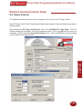
EZ Series Touch Panel
Software Manual
Manual Part Number EZ-PANELEDIT
Revision A
The Most Sensible Automation Products
Direct From the Factory
EZ Series Touch Panel
Software Manual
Manual Part Number EZ-PANELEDIT
Revision A
WARNING!
Programmable control devices such as EZ Series Touch Panel are not fail-safe devices and as such
must not be used for stand-alone protection in any application. Unless proper safeguards are used,
unwanted start-ups could result in equipment damage or personal injury. The operator must be made
aware of this hazard and appropriate precautions must be taken.
In addition, consideration must be given to the use of an emergency stop function that is in
dependent of the programmable controller.
The diagrams and examples in this user manual are included for illustrative purposes only. The
manufacturer cannot assume responsibility or liability for actual use based on the diagrams and
examples.
Caution
Do not press the EZ Series Touch Panel touchscreen with any sharp objects. This practice may
damage the unit beyond repair.
Trademarks
This publication may contain references to products produced and/or offered by other companies.
The product and company names may be trademarked and are the sole property of their respective
owners. EZ Automation disclaims any proprietary interest in the marks and names of others.
Manual Part Number EZ-PANELEDIT
© Copyright 2005, EZAutomation
All Rights Reserved
No part of this manual shall be copied, reproduced, or transmitted in any way without the prior written consent of EZAutomation. EZAutomation retains the exclusive rights to all information included
in this document.
Designed and Built by AVG
4140 Utica Ridge Rd. • Bettendorf, IA 52722-1327
Marketed by EZAutomation
4140 Utica Ridge Road • Bettendorf, IA 52722-1327
Phone: 1-877-774-EASY
• Fax: 1-877-775-EASY •
www.EZAutomation.net
EZ-PANELEDIT
Touch Panel Programming Software User Manual
Table of Contents
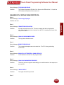
EU Information............................................................................................................................................ix
EZ Series Touch Panel Editor .....................................................................................................................x
Compatibility of Software.......................................................................................................................x
EZ Series Touch Panel Editor Enhancements.......................................................................................x
Enhancement for AB Drivers................................................................................................................. xi
New PLC/Drivers added....................................................................................................................... xi
Chapter 1
Manual Organization....................................................................................................................................2
Introduction...................................................................................................................................................3
What you need to get started.......................................................................................................................3
Hardware...............................................................................................................................................3
Software.................................................................................................................................................3
Need HELP?................................................................................................................................................4
Onscreen HELP.....................................................................................................................................4
Fly-Over HELP.......................................................................................................................................4
PLC HELP..............................................................................................................................................4
Technical Support..................................................................................................................................4
Warranty Repairs...................................................................................................................................4
Out of Warranty Repairs........................................................................................................................4
EZ Series Touch Panel Models....................................................................................................................5
6-inch Monochrome Models..................................................................................................................5
6-inch Color Models...............................................................................................................................6
8-inch Color Models...............................................................................................................................7
10-inch and 15-inch Models...................................................................................................................8
Features.................................................................................................................................................9
PLCs Supported by EZ Series Touch Panel...............................................................................................10
PLC Cable Part Numbers...........................................................................................................................11
................................................................................................................................................................
EZ Series Touch Panel Editor Programming Software...............................................................................12
Installing the Software..........................................................................................................................12
Installation Screens..............................................................................................................................12
EZLaunch Pad............................................................................................................................................15
Chapter 2
Tutorial — Configure PLC..........................................................................................................................18
Tutorial — Create a Project........................................................................................................................19
Step 1...................................................................................................................................................19
Step 2...................................................................................................................................................21
Step 3...................................................................................................................................................28
Chapter 3
Project Setup..............................................................................................................................................32
Decide now if you want to work ON-LINE or OFF-LINE......................................................................32
Step 1 Project Information..................................................................................................................33
SELECT ACTION..........................................................................................................................33
Edit Program OFF-LINE (Write to Panel Later).......................................................................33
Read Program from Panel and Edit OFF-LINE.......................................................................35
Edit Program ON-LINE...........................................................................................................36
A QUICK REVIEW for “ENTER PROJECT INFORMATION”........................................................37
Step 2 Design Your Screens................................................................................................................39
Step 3 Write Your Program to Panel....................................................................................................41
iv
Touch Panel Programming Software User Manual
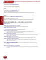
Chapter 4
Objects Menu.............................................................................................................................................44
Button Object.......................................................................................................................................46
Protection Tab................................................................................................................................48
Visibility/Details Tab.......................................................................................................................50
Indicator Button Object........................................................................................................................51
Radio Buttons Object...........................................................................................................................53
Switch Object.......................................................................................................................................56
Step Switch Object...............................................................................................................................58
Tri-State Switch Object........................................................................................................................60
Numeric Entry Object...........................................................................................................................62
Scaling Tab....................................................................................................................................64
Recipe Object......................................................................................................................................66
Thumbwheel Object.............................................................................................................................69
Indicator Light Object...........................................................................................................................71
Numeric Display Object.......................................................................................................................73
Scaling Tab....................................................................................................................................75
Text Objects.........................................................................................................................................76
Static Text......................................................................................................................................76
Triggered Text................................................................................................................................77
Lookup Text...................................................................................................................................79
Message Database.................................................................................................................80
Dynamic Text.................................................................................................................................81
Text Entry.......................................................................................................................................83
Clock Objects.......................................................................................................................................85
Analog Clock.................................................................................................................................85
Digital Clock...................................................................................................................................86
Meter Object........................................................................................................................................87
Alarms Tab.....................................................................................................................................89
Digital Display Tab.........................................................................................................................90
Scaling Tab....................................................................................................................................90
Bar Graph Object.................................................................................................................................92
Digital Display Tab.........................................................................................................................93
Scaling Tab....................................................................................................................................94
Line Graph Object................................................................................................................................95
Pen Tab.........................................................................................................................................97
XY Axis Tab...................................................................................................................................97
PID Faceplate Object...........................................................................................................................99
Legends Tab................................................................................................................................101
Change Screen Object.......................................................................................................................102
Alarm History Object..........................................................................................................................104
System Objects..................................................................................................................................106
Increment/Decrement Hour.........................................................................................................106
Activate Screen Saver.................................................................................................................108
Adjust Contrast............................................................................................................................109
Select Language.......................................................................................................................... 111
Multi-state Indicator............................................................................................................................112
Messages Tab.............................................................................................................................114
Embedding a Data Value......................................................................................................115
Copy Messages....................................................................................................................118
v
Touch Panel Programming Software User Manual
Bitmap Objects...................................................................................................................................120
Dynamic Bitmap Object...............................................................................................................120
To Edit a Bitmap....................................................................................................................122
Bitmap Button .......................................................................................................................125
Multi-state Bitmap........................................................................................................................128
Images Tab............................................................................................................................130
Increment/Decrement Value Object..................................................................................................133
Report Object.....................................................................................................................................135
View File Object.................................................................................................................................141
Unicode Text......................................................................................................................................143
Choosing International Languages....................................................................................................145
Unicode Indicator Light......................................................................................................................147
Unicode Indicator Button....................................................................................................................148
Unicode Multi-state Indicator ............................................................................................................149
Single Position Animation..................................................................................................................151
MultiPosition Animation......................................................................................................................156
Chapter 5
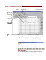
Main Programming Screen.......................................................................................................................161
Title Bar..............................................................................................................................................161
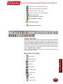
Main Menu Bar...................................................................................................................................161
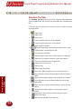
Standard Tool Bar..............................................................................................................................162
Object Tool Bars.................................................................................................................................163
Basic Objects Tool Bar................................................................................................................163
Text Objects ToolBar....................................................................................................................164
System Objects Tool Bar.............................................................................................................164
Bitmap Objects Tool Bar..............................................................................................................164
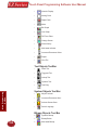
Draw Tool Bar....................................................................................................................................165
Panel Tool Bar....................................................................................................................................165
Status Bar..........................................................................................................................................165
3 Easy Steps Tool Bar........................................................................................................................166
Project Screens Explorer View..........................................................................................................166
Programming Screen.........................................................................................................................168
Chapter 6
Reference ................................................................................................................................................170
File Menu...........................................................................................................................................170
Transfer to Panel.........................................................................................................................173
Edit Menu...........................................................................................................................................175
Tag Name as Address ................................................................................................................177
Objects Overlapping Warning......................................................................................................177
Overlapping Objects Information ................................................................................................177
Pick Attributes . ...........................................................................................................................178
Apply Attributes............................................................................................................................178
Simulate Next and Previous States ............................................................................................179
Screen Menu......................................................................................................................................180
Draw Menu.........................................................................................................................................185
Sizing a Bitmap in Symbol Factory..............................................................................................188
Panel Menu . ....................................................................................................................................189
Setup Menu........................................................................................................................................198
Tag Database..............................................................................................................................198
Tag Cross Reference...................................................................................................................201
Message Database......................................................................................................................215
vi
Touch Panel Programming Software User Manual
Export Messages.........................................................................................................................217
Project Attributes.........................................................................................................................220
Project Description......................................................................................................................230
Select PLC...................................................................................................................................230
Upgrade Firmware.......................................................................................................................230
Tag Verification............................................................................................................................202
Export Tags..................................................................................................................................204
Import Tags..................................................................................................................................205
Importing ControlLogix Tags........................................................................................................208
Alarm Database...........................................................................................................................210
Export Alarms..............................................................................................................................212
Import Alarms..............................................................................................................................213
Import Messages.........................................................................................................................218
Printer Tab.............................................................................................................................220
Passwords Tab......................................................................................................................221
Clock Tab..............................................................................................................................222
Panel to PLC Tab..................................................................................................................223
How do I switch screens from a PLC?..................................................................................225
PLC to Panel Tab..................................................................................................................225
Language Tab.......................................................................................................................227
Alarm Protection Tab.............................................................................................................228
Window Menu....................................................................................................................................232
Help Menu..........................................................................................................................................233
Right Click Menus..............................................................................................................................234
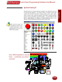
Symbol Factory®...............................................................................................................................235
Appendix A Troubleshooting
Frequently Asked Questions (FAQs)......................................................................................................2
Troubleshooting.....................................................................................................................................5
PLC Driver Error Messages.................................................................................................................15
SIEMENS S7 MPI ADAPTER .................................................................................................................
EZ-Ethernet Error Code Descriptions......................................................................................................
EZ Series Touch Panel Error Messages..............................................................................................61
Appendix B ASCII and ANSI Characters
EZ Series Touch Panel ASCII Characters.............................................................................................2
EZ Series Touch Panel ANSI Characters...............................................................................................5
Appendix C PLC Communications Setup
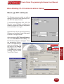
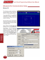
Allen-Bradley PLC Communications Setup...........................................................................................3
MicroLogix DF1 Full Duplex............................................................................................................3
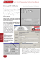
MicroLogix DF1 Half Duplex............................................................................................................4
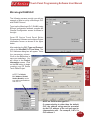
MicroLogix DH485/AIC....................................................................................................................5
SLC 5/03, 5/04, and 5/05 DF1 Full Duplex......................................................................................6
SLC 5/03, 5/04, and 5/05 DF1 Half Duplex.....................................................................................7
SLC 500, 5/01, 5/02 and 5/03 DH485/AIC......................................................................................8
PLC5 DF1........................................................................................................................................9
Data Highway Plus........................................................................................................................10
Remote I/O....................................................................................................................................12
Generic DeviceNet I/O Communications Setup...................................................................................14
DirectLogic PLC Communications Setup.............................................................................................16
Generic EtherNet/IP Communications Setup.......................................................................................17
vii
Touch Panel Programming Software User Manual
General Electric (GE) PLC Communications Setup.............................................................................20
GE 90-30/90-70 SNPX..................................................................................................................20
GE VERSAMAX............................................................................................................................21
Mitsubishi PLC Communications Setup...............................................................................................22
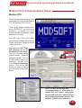
Modicon PLC Communications Setup.................................................................................................23
OMRON C200 and C500 PLC Communications Setup.......................................................................24
Generic Profibus-DP PLC Communications Setup..............................................................................26
Siemens S7 MPI Adapter PLC Communications Setup.......................................................................30
Entivity’s Think & Do (WinPLC) Communications Setup....................................................................32
Aromat PLC.........................................................................................................................................35
Control Techniques..............................................................................................................................36
Control Technology Corporation (CTC)................................................................................................37
Idec......................................................................................................................................................38
Mitsubishi CC Link...............................................................................................................................39
Siemens...............................................................................................................................................40
Square D Symax..................................................................................................................................41
Texas Instruments................................................................................................................................42
Modicon Communications Setup.........................................................................................................43
Universal Ethernet: DF1 for AB, I/P for ControlLogix SRTP for GE and Modbus TCP/IP....................44
Appendix D Setting COM1 for a Printer
Setting COM1 for Printer........................................................................................................................2
viii
Touch Panel Programming Software User Manual
EU Information
The EZ Series Touch Panel is manufactured in compliance with European Union (EU) Directives and carries the
CE mark. EZ Series Touch Panel has been tested under CE Test Standard #EN55011, and is listed under UL File
#E209355. The following information is provided to comply with EU documentation requirements.
Please NOTE: Products with CE marks perform their required functions safely and adhere
to relevant standards as specified by EU Directives provided they are used according
to their intended purpose and that the instructions in this manual are adhered to. The
protection provided by the equipment may be impaired if this equipment is not used in
accordance with this manual. Only replacement parts supplied by EZAutomation or its
agents should be used.
Technical
Support
Consult EZ Series Touch Panel Editor Programming Software Help or you may find answers
to your questions in the operator interface section of our website @ www.EZAutomation.
net. If you still need assistance, please call our technical support from 6 a.m. to Midnight
CST at 1-877-774-EASY or FAX us at 1-877-775-EASY.
SELV Circuits
All electrical circuits connected to the communications port receptacle are rated as Safety
Extra Low Voltage (SELV).
Environmental
Specifications
Operating Temperature
6” White on Blue & Mono non-expandable...............................................0 to 45 °C
6” Color............... 0 to 50 °C
6” Color TFT.............................................................................................0 to 55 °C
8” Color............... 0 to 50 °C
8” Color TFT.............................................................................................0 to 55 °C
10” Color...................................................................................................0 to 55 °C
15” Color...................................................................................................0 to 55 °C
Storage Temperature
6” White on Blue & Mono non-expandable......................................... -20 to +60 °C
6” Color . ............................................................................................ -25 to +60 °C
6” Color TFT....................................................................................... -25 to +65 °C
8” Color............... -25 to +60 °C
8” Color TFT....................................................................................... -25 to +65 °C
10” Color............................................................................................. -25 to +65 °C
15” Color............................................................................................. -25 to +65 °C
Operating Humidity ..................................................10 - 95% R.H>, noncondensing
Air Composition ............................................................No corrosive gases permitted
Preventative
Maintenance
and Cleaning
No preventative maintenance is required. The EZ Series Touch Panel touchscreen
should be cleaned as needed with warm, soapy water. See the EZ Series Touch Panel
Hardware Manual (P/N EZP-PANEL-M) for a list of compatible/incompatible chemicals
and compounds.
ix
Touch Panel Programming Software User Manual
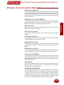
EZ Series Touch Panel Editor
The EZ Series Touch Panel product has been modified to offer new features in:
•
Software
•
Drivers
Compatibility of Software
The EZ Series Touch Panel Editor is compatible with your existing EZ Panels as well as the new EZ Series Touch
Panel models. The EZ Series Touch Panel Editor version 4 provides many new features. These features include
the following:
EZ Series Touch Panel Editor Enhancements
•
Projects saved in a convenient single file: EZ Series Touch Panel Editor software saves screen
projects in multiple files EZ Series Touch Panel ver. 4 software saves the projects in one single file
making copying, moving or backing up projects much easier.
•
Monitoring of tags: Now you can monitor tags on your PC for easy machine diagnosis.
•
Bitmap creation and editing from within the software: EZ Series Touch Panel was probably the
first panel editor allowing you to resize bitmaps from within the editor. With EZ Series Touch Panel
Editor ver. 4, offers you additional bitmap editing features, such as creation, color change, cropping,
etc.
•
EZPackager: New EZ Series Touch Panel software incorporates a unique utility called EZPackager.
EZPackager allows OEMs to distribute their projects to their end users, cutting time and cost for
project maintenance. (See EZPackager User Manual.pdf in your EZ Series Touch Panel install
directory)
•
Overlapping of Objects: Save a great deal of screen real estate by making available a great deal of
information on one screen at any given time.
•
Free Sizing of Touch Objects: Finally, you can make all objects as large or as small as you want
them to be, as the software no longer restricts you to the touch grid, making screen design easier and
more functional.
•
Pick and Apply Styles: When designing screens, there are many attributes assigned to objects,
such as an object’s color, shape, text size, text color... All these details in completing a “style” takes
time! This feature allows you to copy and paste a style from one object to as many as you select.
•
Display of Tag Addresses on Objects: The PLC addressing uses Tag names, so that you can
associate meaningful, easy to remember names to the addresses. Additionally, tags are useful if you
use different PLCs with the same HMI program. You only need to design the HMI program once!
Just change the tag definitions to match the PLC you have to use - saving you a great deal of screen
development and troubleshooting time.
•
Support for Importing New Image Formats: JPEG, GIF, and ICO images are now supported,
allowing you to easily import more images into your projects.
•
New 4,000 Symbol Library: The EZ Series Touch Panel software provides an even larger library of
pre-built objects allowing you to create great new graphical screens.
•
Report object: Send reports from your application to your printer.
•
View File object added for EZCE Touchpanel: Configure a button that when pressed, will launch
a Windows CE File Viewer to view a Windows file. The File Viewer application launched can be
x
Touch Panel Programming Software User Manual
determined both manually and automatically.
Enhancement for AB Drivers
•
Support for ST & Long File types in AB Drivers
•
Support for full range of I/O and direct addressing of I/O for DF1 and Micrologix
•
Support ControlLogix and Compact Logix Tag names
•
Support for binary files (B3:0/0) using the shortcut method of B3/0, B3/1, and B3/2
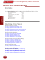
New PLC/Drivers added
•
Aromat
•
Control Techniques - Unidrive 2-wire, 4-wire (binary)
•
Control Technology Corporation (CTC) - CTC2600, 2700, and 5100 (CTC Binary)
•
Idec - Computer Link
•
Mitsubishi - CC Link (CC Link protocol)
•
Siemens S7_200
•
Square D Symax - 300 Series CPU, 400 Series CPU (Symax)
•
Texas Instruments - TI5x5 Series, TI505, TI545-1102, TI545-1104
•
Uni Telway - Telemecanique TSX 37 Micro (UNI-TE Version 1.1)
•
Universal Ethernet: Ethernet/IP, DF1 over Ethernet, Modbus TCP/IP, GE SRTP
xi
Introduction
1
In this chapter....
— Manual Organization
— Introduction
— What you need to get started
— Need HELP?
— Models
— Features
— PLCs Supported by EZ Series Touch Panel
— PLC Cable Part Numbers
— Programming Cable Part Number
— EZ Series Touch Panel Editor Programming
Software Installation
Chapter 1
Touch Panel Programming Software User Manual
Manual Organization
Introduction
The EZ Series Touch Panel Editor Programming Software User Manual is arranged in chapters. A description of
key information contained in each chapter is provided below.
Chapter
2
Description
1
Introduction
Provides Manual Organization, and lists what you need to get started, hardware and
software. Discusses how to get help with questions or problems you might encounter
through Onscreen Help and Technical Support. Provides you with a table listing the
various models, their part numbers and special features. Lists the important features
of all EZ Series Touch Panel models. Lists the PLCs supported by the panels, by
brand, model and protocol. Lists the part numbers for PLC cables and the programming cable. Tells how to install programming software.
2
Tutorial
Provides instructions to create an example (or “demo”) project. Discusses how
to configure a PLC ladder logic program to use with the demo project. Takes you
through the steps necessary to create an EZ Series Touch Panel project using the
programming software. Shows you how to transfer the project to the panel, and testing the project once transferred.
3
Project Setup
Discusses ON-LINE and OFF-LINE configuration options. Tells you how to set up a
project by entering project information (Step 1). Discusses screen design (Step 2), and
how to transfer the project to the panel (Step 3).
4
Objects
Provides step-by-step instructions for configuring each of the EZ Series Touch Panel
objects.
5
Main Programming Screen
Familiarizes you with the EZ Series Touch Panel Editor Programming Software work
area. Briefly identifies and describes the main features of the screen, where you will
design your EZ Series Touch Panel operator interface screens.
6
Reference
Provides more details on menu commands. Takes you through the main menu bar
item by item, command by command, with instructions. Contains information on the
various tool bars and the status bar. Describes right click menus and Screens Explorer
view.
A
Appendix A Troubleshooting
Aids in diagnosing problems you might encounter when installing or operating your
EZ Series Touch Panel. Provides steps to take to isolate and correct problems. Lists
panel error messages, programming software error messages, and PLC Driver Error
messages.
B
Appendix B Characters
Provides a list of the ASCII Characters supported by the EZ Series Touch Panel. This
information may be useful when creating a Text Entry or Dynamic Text object.
C
Appendix C PLC Communications Setup
Provides instructions on how to set up most PLC Types to communicate with the EZ
Series Touch Panel.
D
Appendix D Setting COM1 to Printer
Provides instructions on how to set COM1 on the EZ Series Touch Panel to “Printer.”
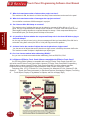
Touch Panel Programming Software User Manual
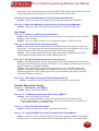
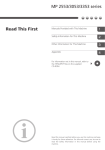
There are two manuals that you will need for installation — this manual, the
EZ Series Touch Panel Editor Programming Software User Manual, and the
EZ Series Touch Panel Hardware User Manual (P/N EZ-PANEL-M) shipped
with your EZ Series Touch Panel touchpanel.
EZ Series Touch
These manuals will take you through the steps necessary to get your EZ
Series Touch Panel up and running in the shortest possible time. Although
your familiarity with programmable graphic operator interface devices will
determine how quickly you move through the steps — it’s as easy as
1 — 2 — 3.
Install the EZ Series Touch Panel
using the instructions in the
Hardware Manual.
Program the EZ Series Touch
Panel using the instructions in
this Software Manual.
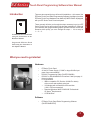
What you need to get started
Hardware
•
•
EZ Series Touch Panel
24 Volt DC Power Supply (1.5 AMP or larger Slo-Blo input
power fuse recommended)
•
RS-232C Programming Cable (P/N EZ-PGMCBL)
•
RS-232C or RS-422A/485A PLC Interface Cable (see page 11
for part numbers)
•
PC requirements:
— IBM or compatible PC (Pentium 166 MHZ or better)
with a mouse and separate serial port
— VGA display with at least 800 x 600 resolution (1024 x 768 recommended)
— Standard Windows 98/NT4.0/2000/XP Professional/
XP Home® Requirements
— CD ROM Drive
Software
•
EZ Series Touch Panel Editor Programming Software
(P/N EZ-PANELEDIT)
3
Introduction
Introduction
Introduction
Touch Panel Programming Software User Manual
Introduction
Need HELP?
PLEASE NOTE: The Troubleshooting section (Appendix A) should be able to help you with most problems you might encounter.
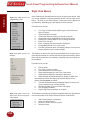
Onscreen HELP
One of the most important features of the EZ Series Touch Panel Editor
Programming Software is the availability of context sensitive onscreen help.
To access the Help windows, simply press the F1 function key while on the
topic where you need help. For example, if you need help while working
with screens, press the F1 function key while in that area and a popup
window will be displayed. You may also click on the Help button located
at the bottom of most dialog boxes to go to the help topic.
Fly-Over HELP
When the mouse cursor comes to rest over any tool bar or object button
for a short while, a small window will appear containing a brief description
of the function of that particular button. The window will disappear as soon
as the cursor has been moved off the button.
PLC HELP
If you need help with the PLC to EZ Series Touch Panel Interface, consult
the EZ Series Touch Panel Editor Programming Software Help. Each
PLC Driver has a Help Topic that lists the error messages and provides
an explanation for each. Also provided are PLC to EZ Series Touch Panel
wiring diagrams.
Technical Support
Although most questions can be answered with EZ Series Touch Panel
HELP or the manuals, you may find answers to your questions in the
operator interface section of our web site @ www.EZAutomation.net. If
you still need assistance, please call our technical support from 6 a.m. to
Midnight at 1-877-774-EASY or FAX us at 1-877-775-EASY.
Warranty Repairs
If your EZ Series Touch Panel is under warranty, contact www.
EZAutomation.net or call us @ 1-877-774-EASY.
Out of Warranty Repairs
If your EZ Series Touch Panel is out of warranty, contact EZAutomation’s
Service Department for an evaluation of repair costs @ 1-877-774EASY. You can then decide whether it is more economical to proceed with
factory repairs or purchase a new panel.
4
Touch Panel Programming Software User Manual
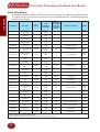
EZ Series Touch Panel Models
6-inch Monochrome Models
Description
User
Memory
Field
Expandable
User RAM?
EZ-S6M-R
6” Mono with
Standard Bezel
256KB
No
No
See Note below
NEMA 4,
4X
*EZ-S6W-RS
6” Mono White
on Blue with Slim
Bezel
256KB
No
No
All Serial Drivers
NEMA 1,
FDA
*EZ-S6W-RSU
6” Mono White
on Blue with Slim
Bezel
256KB
No
No
ONLY Universal
Ethernet
NEMA 1,
FDA
EZ-S6M-RS
6” Mono with Slim
Bezel
256KB
No
No
See Note below
NEMA 1,
FDA
EZ-S6M-F
6” Mono with
Standard Bezel
512KB
Yes, to 1 or
2 MB
Yes
All, plus EZ
Ethernet
NEMA 4,
4X
EZ-S6M-FH
6” Mono with
Standard Bezel
512KB
Yes, to 1 or
2 MB
Yes
All, plus AB DH+
and Remove I/O
NEMA 4,
4X
EZ-S6M-FS
6” Mono with Slim
Bezel
512KB
Yes, to 1 or
2 MB
Yes
All, plus EZ
Ethernet
NEMA 1,
FDA
EZ-S6M-FSH
6” Mono with Slim
Bezel
512KB
Yes, to 1 or
2 MB
Yes
All, plus AB DH+
and Remove I/O
NEMA 1,
FDA
*EZ-S6M-FSD
6” Mono with Slim
Bezel
512KB
Yes, to 1 or
2 MB
Yes
All, plus DeviceNet
NEMA 1,
FDA
*EZ-S6M-FSE
6” Mono with Slim
Bezel
512KB
Yes, to 1 or
2 MB
Yes
All, plus Ethernet
I/P
NEMA 1,
FDA
*EZ-S6M-FSM
6” Mono with Slim
Bezel
512KB
Yes, to 1 or
2 MB
Yes
All, plus MB+
NEMA 1,
FDA
*EZ-S6M-FSP
6” Mono with Slim
Bezel
512KB
Yes, to 1 or
2 MB
Yes
All, plus Profibus
NEMA 1,
FDA
*EZ-S6M-FST
6” Mono Grayscale
with Slim Bezel
512KB
Yes, to 1 or
2 MB
Yes
All, plus ModBus
TCP/IP
NEMA 1,
FDA
*EZ-S6M-FSC
6” Mono Grayscale
with Slim Bezel
512KB
Yes, to 1 or
2 MB
Yes
All, plus CC Link
NEMA 1,
FDA
*EZ-S6M-FSU
6” Mono Grayscale
with Slim Bezel
512KB
Yes, to 1 or
2 MB
Yes
ONLY Universal
Ethernet
NEMA 1,
FDA
*EZ-S6M-ES
6” Mono Grayscale
with Slim Bezel
512KB
Yes, to 1 or
2 MB
Yes
ONLY EZ Series
PLC
NEMA 1,
FDA
PLC Drivers
Upported?
NEMA
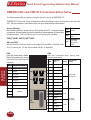
EZAutomation EZ Series Touch Panel NEMA Ratings
The NEMA rating of all operator interface products in this manual relates to only the front bezel since only the front bezel is exposed to the external
environment and the backend is enclosed inside an appropriately sealed enclosure used by the customer. The Touchpanels in this manual have either
NEMA 1 FDA Compliant or NEMA 4, 4X (indoor) rating. Please note that the touchpanels that are rated NEMA 1 FDA Compliant can handle typical
NEMA 4, 4X environments such as water splashing or hosedown. The only reason these panels do not have NEMA 4, 4X rating is because the plastic
material used for NEMA 1 FDA Compliant models does not support the flame retardancy required for NEMA 4 models.
5
Introduction
Introduction
Part Number
Nonvolatile Flash
Backup
Card Option
for Program
Backup?
Touch Panel Programming Software User Manual
Introduction
6-inch Color Models
In the table below are the 6-inch Color EZ Series Touch Panel models. If using an option board connector,
you cannot use the PLC port at the same time to connect to another type PLC. The panel supports only
one PLC driver at a time.
Part Number
EZ-S6C-K
EZ-S6C-KS
EZ-S6C-F
EZ-S6C-FH
EZ-S6C-FS
Description
6” STN Color with
Standard Bezel
6” STN Color with
Slim Bezel
6” STN Color with
Standard Bezel
6” STN Color with
Standard Bezel
6” STN Color with
Slim Bezel
User
Memory
512KB
512KB
512KB
512KB
512KB
Field
Expandable
User RAM?
Yes, to 1 or
2 MB
Yes, to 1 or
2 MB
Yes, to 1 or
2 MB
Yes, to 1 or
2 MB
Yes, to 1 or
2 MB
Nonvolatile
Flash Backup
Card Option
for Program
Backup?
PLC Drivers Upported?
NEMA
Yes
ONLY Direct Logic PLC
Yes
ONLY Direct Logic PLC
Yes
All, plus EZ Ethernet
Yes
All, plus AB DH+ and Remote I/O
Yes
All, plus EZ Ethernet
NEMA 4,
4X
NEMA 1,
FDA
NEMA 4,
4X
NEMA 4,
4X
NEMA 1,
FDA
EZ-T6C-FS
6” TFT Color with Slim
Bezel
512KB
Yes, to 1 or
2 MB
Yes
All, plus EZ Ethernet
NEMA 1,
FDA
*EZ-S6C-FSD
6” STN Color with
Slim Bezel
512KB
Yes, to 1 or
2 MB
Yes
All, plus DeviceNet
NEMA 1,
FDA
Yes
All, plus DeviceNet
Yes
All, plus Ethernet I/P
Yes
All, plus Ethernet I/P
Yes
All, plus AB DH+ and Remote I/O
*EZ-T6C-FSD
*EZ-S6C-FSE
*EZ-T6C-FSE
EZ-S6C-FSH
EZ-T6C-FSH
EZ-S6C-FSM
EZ-T6C-FSM
EZ-S6C-FSP
EZ-T6C-FSP
*EZ-S6C-FST
*EZ-T6C-FST
*EZ-T6C-FSC
*EZ-S6C-FSU
*EZ-T6C-FSU
*EZ-S6C-ES
EZ-T6C-ES
6” TFT Color with Slim
Bezel
6” STN Color with
Slim Bezel
6” TFT Color with Slim
Bezel
512KB
512KB
512KB
6” STN Color with
Slim Bezel
6” TFT Color with Slim
Bezel
6” STN Color with
Slim Bezel
6” TFT Color with Slim
Bezel
6” STN Color with
Slim Bezel
512KB
6” TFT Color with Slim
Bezel
512KB
6” STN Color with
Slim Bezel
6” TFT Color with Slim
Bezel
6” STN Color with
Slim Bezel
6” STN Color with
Slim Bezel
6” TFT Color with Slim
Bezel
6” STN Color with
Slim Bezel
6” TFT Color with Slim
Bezel
512KB
512KB
512KB
512KB
512KB
512KB
512KB
512KB
512KB
512KB
512KB
Yes, to 1 or
2 MB
Yes, to 1 or
2 MB
Yes, to 1 or
2 MB
NEMA 1,
FDA
Yes, to 1 or
2 MB
Yes, to 1 or
2 MB
Yes, to 1 or
2 MB
Yes, to 1 or
2 MB
Yes, to 1 or
2 MB
Yes
All, plus AB DH+ and Remote I/O
Yes
All, plus MB+
Yes
All, plus MB+
Yes
All, plus Profibus
Yes, to 1 or
2 MB
Yes
All, plus Profibus
NEMA 1,
FDA
Yes
All, plus ModBus TCP/IP
Yes
All, plus ModBus TCP/IP
Yes
All, plus CC Link
Yes
ONLY Universal Ethernet
Yes
ONLY Universal Ethernet
Yes
ONLY EZPLC
Yes
ONLY EZPLC
NEMA 1,
FDA
NEMA 1,
FDA
NEMA 1,
FDA
NEMA 1,
FDA
NEMA 1,
FDA
NEMA 1,
FDA
NEMA 1,
FDA
Yes, to 1 or
2 MB
Yes, to 1 or
2 MB
Yes, to 1 or
2 MB
Yes, to 1 or
2 MB
Yes, to 1 or
2 MB
Yes, to 1 or
2 MB
Yes, to 1 or
2 MB
*Indicates NEW EZ Series Touch Panel Models.
NOTE: Suppots Automation Direct (Direct Logic) serial drivers including H2-WPLC-XX.
6
NEMA 1,
FDA
NEMA 1,
FDA
NEMA 1,
FDA
NEMA 1,
FDA
NEMA 1,
FDA
NEMA 1,
FDA
NEMA 1,
FDA
Touch Panel Programming Software User Manual
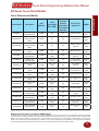
8-inch Color Models
User
Memory
Field
Expandable User
RAM?
Nonvolatile
Flash Backup
Card Option
for Program
Backup?
Part Number
Description
PLC Drivers Upported?
NEMA
EZ-S8C-F
8” STN Color with Slim Bezel
512KB
Yes, to 1 or 2 MB
Yes
All, plus EZ Ethernet
NEMA 4, 4X
EZ-T8C-F
8” TFT Color with Slim Bezel
512KB
Yes, to 1 or 2 MB
Yes
All, plus EZ Ethernet
NEMA 4, 4X
EZ-S8C-FH
8” STN Color with Slim Bezel
512KB
Yes, to 1 or 2 MB
Yes
EZ-T8C-FH
8” TFT Color with Slim Bezel
512KB
Yes, to 1 or 2 MB
Yes
All, plus AB DH+ and
Remote I/O
All, plus AB DH+ and
Remote I/O
NEMA 4, 4X
NEMA 4, 4X
EZ-S8C-FS
8” STN Color with Slim Bezel
512KB
Yes, to 1 or 2 MB
Yes
All, plus EZ Ethernet
NEMA 1, FDA
*EZ-S8C-FSD
8” STN Color with Slim Bezel
512KB
Yes, to 1 or 2 MB
Yes
All, plus DeviceNet
NEMA 1, FDA
*EZ-S8C-FD
8” STN Color with Slim Bezel
512KB
Yes, to 1 or 2 MB
Yes
All, plus DeviceNet
NEMA 4, 4X
*EZ-T8C-FD
8” TFT Color with Slim Bezel
512KB
Yes, to 1 or 2 MB
Yes
All, plus DeviceNet
NEMA 4, 4X
*EZ-S8C-FSE
8” STN Color with Slim Bezel
512KB
Yes, to 1 or 2 MB
Yes
All, plus Ethernet I/P
NEMA 1, FDA
*EZ-S8C-FE
8” STN Color with Slim Bezel
512KB
Yes, to 1 or 2 MB
Yes
All, plus Ethernet I/P
NEMA 4, 4X
*EZ-T8C-FE
8” TFT Color with Slim Bezel
512KB
Yes, to 1 or 2 MB
Yes
All, plus Ethernet I/P
NEMA 4, 4X
EZ-S8C-FSH
8” STN Color with Slim Bezel
512KB
Yes, to 1 or 2 MB
Yes
All, plus AB DH+ and
Remote I/O
NEMA 1, FDA
*EZ-S8C-FSM
8” STN Color with Slim Bezel
512KB
Yes, to 1 or 2 MB
Yes
All, plus MB+
NEMA 1, FDA
*EZ-S8C-FM
8” STN Color with Slim Bezel
512KB
Yes, to 1 or 2 MB
Yes
All, plus MB+
NEMA 4, 4X
*EZ-T8C-FM
8” TFT Color with Slim Bezel
512KB
Yes, to 1 or 2 MB
Yes
All, plus MB+
NEMA 4, 4X
*EZ-S8C-FSP
8” STN Color with Slim Bezel
512KB
Yes, to 1 or 2 MB
Yes
All, plus Profibus
NEMA 1, FDA
*EZ-S8C-FP
8” STN Color with Slim Bezel
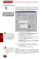
512KB
Yes, to 1 or 2 MB
Yes
All, plus Profibus
NEMA 4, 4X
*EZ-T8C-FP
8” TFT Color with Slim Bezel
512KB
Yes, to 1 or 2 MB
Yes
All, plus Profibus
NEMA 4, 4X
*EZ-S8C-FST
8” Color with Slim Bezel
512KB
Yes, to 1 or 2 MB
Yes
All, plus ModBus TCP/IP
NEMA 1, FDA
*EZ-S8C-FT
8” STN Color with Slim Bezel
512KB
Yes, to 1 or 2 MB
Yes
All, plus ModBus TCP/IP
NEMA 4, 4X
*EZ-T8C-FT
8” TFT Color with Slim Bezel
512KB
Yes, to 1 or 2 MB
Yes
All, plus ModBus TCP/IP
NEMA 4, 4X
*EZ-S8C-FSC
8” STN Color with Slim Bezel
512KB
Yes, to 1 or 2 MB
Yes
All, plus CC Link
NEMA 1, FDA
*EZ-S8C-FC
8” STN Color with Slim Bezel
512KB
Yes, to 1 or 2 MB
Yes
All, plus CC Link
NEMA 4, 4X
*EZ-T8C-FC
8” TFT Color with Slim Bezel
512KB
Yes, to 1 or 2 MB
Yes
All, plus CC Link
NEMA 4, 4X
*EZ-S8C-FSU
8” Color with Slim Bezel
512KB
Yes, to 1 or 2 MB
Yes
ONLY Universal Ethernet
NEMA 1, FDA
*EZ-S8C-FU
8” STN Color with Slim Bezel
512KB
Yes, to 1 or 2 MB
Yes
ONLY Universal Ethernet
NEMA 4, 4X
*EZ-T8C-FU
8” TFT Color with Slim Bezel
512KB
Yes, to 1 or 2 MB
Yes
ONLY Universal Ethernet
NEMA 4, 4X
*EZ-T8C-E
8” TFT Color with Slim Bezel
512KB
Yes, to 1 or 2 MB
Yes
ONLY EZ Series PLC
NEMA 4, 4X
*Indicates NEW EZ Series Touch Panel Models.
7
Introduction
Introduction
In the table below are the 8-inch EZ Series Touch Panel models. If using an option board connector, you
cannot use the PLC port at the same time to connect to another type PLC. The panel supports only one
PLC driver at a time.
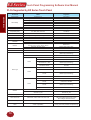
Touch Panel Programming Software User Manual
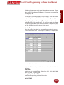
Introduction
10-inch and 15-inch Models
In the table below are the 10-inch and 15-inch EZ Series Touch Panel models. If using an option board
connector, you cannot use the PLC port at the same time to connect to another type PLC. The panel supports
only one PLC driver at a time.
Part Number
Description
User
Memory
Field
Expandable User
RAM?
Nonvolatile
Flash Backup
Card Option
for Program
Backup?
EZ-T10C-F
10.4” TFT Color with Slim Bezel
512KB
Yes, to 1 or 2 MB
EZ-T10C-FH
10.4” TFT Color with Slim Bezel
512KB
Yes, to 1 or 2 MB
PLC Drivers Upported?
NEMA
Yes
All Serial Drivers
NEMA 4, 4X
Yes
All, plus AB DH+ and
Remote I/O
NEMA 4, 4X
EZ-T10C-FS
10.4” TFT Color with Slim Bezel
512KB
Yes, to 1 or 2 MB
Yes
All, plus EZ Ethernet
NEMA 1, FDA
EZ-T10C-FD
10.4” TFT Color with Slim Bezel
512KB
Yes, to 1 or 2 MB
Yes
All, plus DeviceNet I/O
NEMA 4, 4X
NEMA 1, FDA
EZ-T10C-FSD
10.4” TFT Color with Slim Bezel
512KB
Yes, to 1 or 2 MB
Yes
All, plus DeviceNet I/O
EZ-T10C-FE
10.4” TFT Color with Slim Bezel
512KB
Yes, to 1 or 2 MB
Yes
All, plus Ethernet I/P
NEMA 4, 4X
EZ-T10C-FSE
10.4” TFT Color with Slim Bezel
512KB
Yes, to 1 or 2 MB
Yes
All, plus Ethernet I/P
NEMA 1, FDA
EZ-T10C-FSH
10.4” TFT Color with Slim Bezel
512KB
Yes, to 1 or 2 MB
Yes
All, plus AB DH+ and
Remote I/O
NEMA 1, FDA
EZ-T10C-FM
10.4” TFT Color with Slim Bezel
512KB
Yes, to 1 or 2 MB
Yes
All, plus Modbus Plus
NEMA 4, 4X
EZ-T10C-FSM
10.4” TFT Color with Slim Bezel
512KB
Yes, to 1 or 2 MB
Yes
All, plus Modbus Plus
NEMA 1, FDA
EZ-T10C-FP
10.4” TFT Color with Slim Bezel
512KB
Yes, to 1 or 2 MB
Yes
All, plus Profibus
NEMA 4, 4X
EZ-T10C-FSP
10.4” TFT Color with Slim Bezel
512KB
Yes, to 1 or 2 MB
Yes
All, plus Profibus
NEMA 1, FDA
EZ-T10C-FT
10.4” TFT Color with Slim Bezel
512KB
Yes, to 1 or 2 MB
Yes
All, plus ModBus TCP/IP
NEMA 4, 4X
NEMA 1, FDA
EZ-T10C-FST
10.4” TFT Color with Slim Bezel
512KB
Yes, to 1 or 2 MB
Yes
All, plus ModBus TCP/IP
EZ-T10C-FC
10.4” TFT Color with Slim Bezel
512KB
Yes, to 1 or 2 MB
Yes
All, plus CC Link
NEMA 4, 4X
EZ-T10C-FSC
10.4” TFT Color with Slim Bezel
512KB
Yes, to 1 or 2 MB
Yes
All, plus CC Link
NEMA 1, FDA
EZ-T10C-FU
10.4” TFT Color with Slim Bezel
512KB
Yes, to 1 or 2 MB
Yes
ONLY Universal Ethernet
NEMA 4, 4X
EZ-T10C-FSU
10.4” TFT Color with Slim Bezel
512KB
Yes, to 1 or 2 MB
Yes
ONLY Universal Ethernet
NEMA 1, FDA
EZ-T10C-E
10.4” TFT Color with Slim Bezel
512KB
Yes, to 1 or 2 MB
Yes
ONLY EZPLC
NEMA 4, 4X
EZ-T15C-FS
15” TFT Color with Slim Bezel
1MB
Yes, to 1 or 2 MB
Yes
All, plus EZ Ethernet
NEMA 1, FDA
EZ-T15C-FSD
15” TFT Color with Slim Bezel
1MB
Yes, to 1 or 2 MB
Yes
All, plus DeviceNet I/O
NEMA 1, FDA
EZ-T15C-FSE
15” TFT Color with Slim Bezel
1MB
Yes, to 1 or 2 MB
Yes
All, plus Ethernet IP
NEMA 1, FDA
EZ-T15C-FSH
15” TFT Color with Slim Bezel
1MB
Yes, to 1 or 2 MB
Yes
All, plus AB DH+ and
Remote I/O
NEMA 1, FDA
EZ-T15C-FSM
15” TFT Color with Slim Bezel
1MB
Yes, to 1 or 2 MB
Yes
All, plus Modbus Plus
NEMA 1, FDA
EZ-T15C-FSP
15” TFT Color with Slim Bezel
1MB
Yes, to 1 or 2 MB
Yes
All, plus Profibus
NEMA 1, FDA
EZ-T15C-FST
15” TFT Color with Slim Bezel
1MB
Yes, to 1 or 2 MB
Yes
All, plus Modbus TCP/IP
NEMA 1, FDA
EZ-T15C-FSC
15” TFT Color with Slim Bezel
1MB
Yes, to 1 or 2 MB
Yes
All, plus CC Link
NEMA 1, FDA
EZ-T15C-FSU
15” TFT Color with Slim Bezel
1MB
Yes, to 1 or 2 MB
Yes
ONLY Universal Ethernet
NEMA 1, FDA
8
Touch Panel Programming Software User Manual
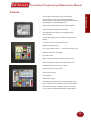
Features
•
Pre-built panel components for easy screen design
•
Screen Objects such as: Toggle Switch, Slide Switch,
Selector Switch, Throw Switch, Thumbwheel Object, Meters,
PID Face plates, and Analog/Digital Clock
•
Flash memory-based design for easy firmware upgrade
•
Field expandable user RAM (not all models)
•
Nonvolatile flash card option for user program backup
(not all models)
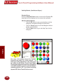
•
Color models support 128-color palette for components and bitmaps
•
16 shades of gray on monochrome models
•
Multiple languages (up to 9)
•
PLC
Two communications ports — Computer (RS-232C) and
•
Up to 999 screens
•
Built-in clock and calendar or reference the PLC clock
•
Built-in soft keypad for numeric and alphanumeric entry
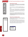
•
Password Protection for every touch object
•
Passwords for up to 8 user groups
•
16 level undo and redo
•
Import bitmaps
•
Serial Printer support
Introduction
Introduction
(RS-232C, RS-422A, or RS-485A)
•
40-character tag names allow you to use meaningful names for PLC memory locations instead of cryptic PLC addresses
•
New features including: overlapping of objects, free-sizing of touch objects, Pick and Apply Attributes, display address 9
Touch Panel Programming Software User Manual
Introduction
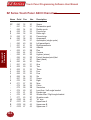
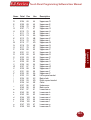
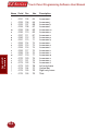
PLCs Supported by EZ Series Touch Panel
PLC Brand
Model
Protocols
Supported
EZAutomation
EZ Series PLC
MicroLogix 1000/1200/1500, SLC500,5/01, /02, /03
MicroLogix 1000/1200/1500SLC 5/03, 5/04, and 5/05
SLC 504, PLC5
PLC 5
PLC 2, 3, and 5
Aromat
Unidrive 2-wire, 4-wire
EZ Protocol
DH 485/AIC/AIC+
DF1 Half Duplex/DF1 Full Duplex
DH+ (Option Card)
DF1
Remote I/O (with DH+ Plus Option Card)
Mewtocol COM
Binary
Allen Bradley
Aromat
Control Techniques
Control Technology
Corporation (CTC)
DeviceNet
Ethernet
General Electric
Idec
Mitsubishi
Modicon
Omron
Profibus
CTC 2600, 2700, and 5100
CTC Binary
DeviceNet I/O
Control Logic, Micro Logic, Compact Logic, GE Versamax
90/30 and 90/70 Versamax
Idec
FX Series (all)
CC Link
984 CPU, Quantum 113 CPU, AEG Modicon Micro Series
110, CPU: 311-xx, 411-xx, 512-xx, 612-xx
984 Series, Qunatum Series
C200, C500, CQM1, CPM1, CPM2
Profibus-DP
DeviceNet I/O (OptionCard)
Ethernet I/P, SRTP, DF1, Modbus TCP/IP
SNPX/SNP
Computer Link
FX, Direct
CC Link Protocol
DL105
DL105
DL205
Modbus RTU
Modicon Plus (Option Card)
Host Link
Generic Profibus DP(Option Card)
K-Sequence, DirectNet,
Modbus (Koyo Addressing)
K-Sequence
D2-230
K-Sequence
D2-240
K-Sequence; DirectNet
D2-250/D2-250 - 1/260
K-Sequence; DirectNet;
ModBus (Koyo addressing)
D2-240/250 w/DCM
DirectNet
D3-330/330P
DirectNet
Direct Logic
DL305
D3-340
DirectNet
D3-350
K-Sequence; DirectNet;
ModBus (Koyo addressing)
D3-350 w/DCM
DirectNet
D4-430
K-Sequence; DirectNet
D4-440
K-Sequence; DirectNet
D4-450
K-Sequence; DirectNet;
ModBus (Koyo addressing)
All with DCM
DirectNet
DL405
Siemens S7 MPI Adaptor
3964R
Siemens S7_200
Siemens S7_200
Square D Symax
300 Series CPU, 400 Series CPU
Symax
Texas Instruments
TI5X5 Series, TI505, TI545-1102, TI545-1104
TBP (Transparent ByteProtocol) or NITP
(Non-Intelligent Terminal Protocol)
Uni-Telway
Telemecanique TSX 37 Micro
UNI-TE (Version 1.1)
Other
H2- WinPLC (Entivity (Think & Do) V5.2 orlater, check for
version compatability
Entivity (Think & Do) Modbus RTU (Serial Port)
Siemens
10
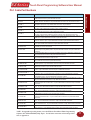
Touch Panel Programming Software User Manual
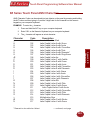
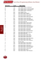
PLC Cable Part Numbers
EZ-CBL
EZ-2CLB
EZ-2CBL-1
EZ-3CBL
EZ-4CBL-1
EZ-4CBL-2
EZ-MLOGIX-CBL
EZ-SLC-232-CBL
EZ-PLC5-232-CBL1
EZ-DH485-CBL
EZ-90-30-CBL
EZ-MITSU-CBL
EZ-MITSU-CBL-1
EZ-S7MPI-CBL
EZ-OMRON-CBL
EZ-ARCOL-CBL
EZ-CTRLUNI-CBL
EZ-CTRLUNI-CBL-1
EZ-CTCBI-CBL
EZ-IDECM-CBL
EZ-MODUNI-CBL
EZ-MODRTU-CBL
EZ-S7200-CBL
EZ-SYMAX-CBL
EZ-TX505-CBL
EZ-IDECS-CBL
EZ-TX545-CBL
EZ-TX545-CBL1
Cable Description
RS232C shielded cable to connect any EZ Series Touch Panel to EZ Series PLC. 15 pin Dshell male connector to 9 pin D-shell male connector.
10’ RS232C shielded cable to connect any EZ Series Touch Panel to DL05, DL06, DL105,
DL205, D3-350 or D4-450 CPU. 15 pin D-shell male connector to RJ 12 modular connector.
10’ RS232C shielded cable to connect any EZ Series Touch Panel to a DL06, D2-250(-1) or D2260 (bottom port) CPU. 15 pin D-shell male connector to 15 pin male HD.
10’ RS232C shielded cable to connect any EZ Series Touch Panel to a D3-340 CPU top or bottom port. 15 pin D-shell male connector to RJ11 modular connector.
10’ RS232C shielded cable to connect any EZ Series Touch Panel to DL 405 (top port) CPU. 15
pin D-shell male connector to 15 pin D-shell male connector.
10’ RS 232C shielded cable to connect any EZ Series Touch Panel to a D2-DCM, D3-350 (bottom port), a D3-232-DCU installed on D3-333 or D3-340, or DL 405 (bottom point) CPU.
6’ shielded cable to connect any EZ Series Touch Panel to an AB Micrologix 1000, 1200, or
1500 CPU. 15 pin D-shell male connector to 8 pin DIN connector
10’ RS232C shielded cable to connect any EZ Series Touch Panel to an AB SLC 5/03, 5/04 or
5/05 CPU with DF-1 port. 15 pin D-shell male connector to 9 pin D-shell female connector.
10’ RS232C shielded cable to connect any EZ Series Touch Panel to an AB PLC5 CPU with DF1
port. 15 pin D-shell male connector to 25 pin D-shell male connector.
10’ RS232C shielded cable to connect any EZ Series Touch Panel to an AB SLC 500 CPU with
a DH485 port and 747-A/C Module.
10’ RS232C shielded cable to connect any EZ Series Touch Panel to GE Fanuc Series 90/30,
90/70 serial port using SNPX protocol. 15 pin D-shell male connector to 15 pin D-shell male
connector.
10’ RS422 shielded cable to connect any EZ Series Touch Panel to Mitsubishi FX series CPU.
15 pin D-shell male connector to 25 pin D-shell male connector.
10’ RS422 shielded cable to connect any EZ Series Touch Panel to Mitsubishi FX series CPU.
15 pin D-shell male connector to 8 pin min. din.
10’ shielded cable to connect any EZ Series Touch Panel to Siemens Simatic S7 series CPU. 15
pin D-shell male connector to 9 pin D-shell connector
10’ RS232C shielded cable to connect any EZ Series Touch Panel to Omron C200 or C500 with
Hostlink protocol. 15 pin D-shell male connector to 25 pin D-shell male connector.
10’ RS232C shielded cable to connect any EZ Series Touch Panel to Aromat PLC. 15 pin DShell male connector to 5 pin mini DIN male connector.
10’ RS422 shielded cable to connect any EZ Series Touch Panel to Control Techniques Unidrive
4-wire. 15 pin D-Shell male connector to 9 pin D-shell female connector.
10’ RS485 shielded cable to connect any EZ Series Touch Panel to Control Techniques
Unidrive 2-wire. 15 pin D-Shell male connector to 9 pin D-shell female connector.
10’ RS232 shielded cable to connect any EZ Series Touch Panel to Control Technology
Corportation (CTC). 15 pin D-Shell male connector to RJ12.
10’ RS485 shielded cable to connect any EZ Series Touch Panel to IDEC Micro 3 PLC.
15 pin D-Shell male connector to 8-pin Mini DIN connector.
10’ RS485 shielded cable to connect any EZ Series Touch Panel to Modicon Uni-Telway
Telemecanique TSX 37 Micro PLC. 15 pin D-Shell male connector to 8 pin mini DIN
connector.
10’ RS232C shielded cable to connect any EZ Series Touch Panel to Modicon Modbus
RTU. 15 pin D-Shell male connector to 9 pin D-shell male connector.
10’ RS485 shielded cable to connect any EZ Series Touch Panel to Siemens S7 200
PLC. 15 pin D-Shell male connector to 9 pin D-shell male connector.
10’ RS422 shielded cable to connect EZ Series Touch Panel to Square-D symax. 15 pin
D-Shell male connector to 9 pin D-shell male connector.
10’ RS232C shielded cable to connect any EZ Series Touch Panel connect to Texas
Instrument 505 Series PLC. 15 pin D-Shell male connector to 9 pin D-shell female
connector.
10’ RS232C shielded cable to connect any EZ Series Touch Panel to IDEC Micro Smart
PLC. 15 pin D-Shell male connector to 8 pin mini DIN male connector.
10’ RS422 shielded cable to connect any EZ Series Touch Panel to Texas Instrument
545-1102 series PLC. 15 pin D-Shell male connector to 9 pin D-shell male connector.
10’ RS422 shielded cable to connect any EZ Series Touch Panel to Texas Instrument
545-1104 PLC. 15 pin D-Shell male connector to 9 pin D-shell female connector.
NOTE: See Appendix A for cable pinouts, or use the EZ Series Touch Panel Editor Programming
Software (P/N EZ-PANELEDIT) Help Topics. For RS-422A connections to DirectLogic PLCs
also see Appendix A.
11
Introduction
Introduction
Cable Part Number
Touch Panel Programming Software User Manual
Introduction
EZ Series Touch Panel Editor Programming
Software
EZ Series Touch Panel models are configured with software running on an
IBM or compatible personal computer. This software is available through
EZ Automation, part number EZ-PANELEDIT. The panel can be configured
on-line or off-line (See page 3 for requirements).
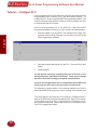
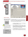
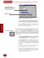
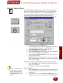
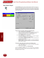
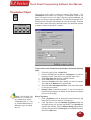
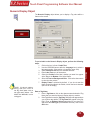
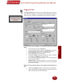
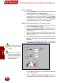
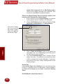
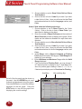
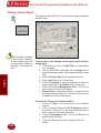
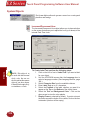
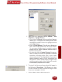
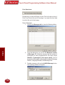
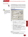
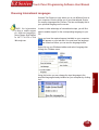
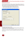
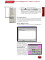
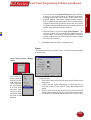
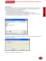
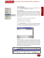
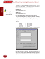
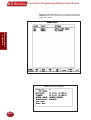
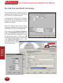
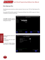
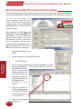
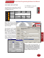
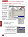
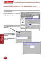
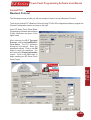
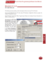
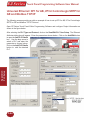
Installing the Software
Perform the following steps to install the EZ Series Touch Panel Editor
Programming Software onto your PC.
• Place the CD into your CD ROM drive.
The install program should launch automatically. If it does not,
perform the following steps.
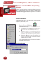
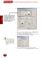
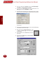
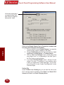
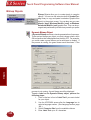
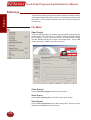
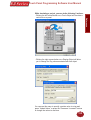
1
From Windows click on the Start Button, and then click on
Run from the menu. The Run dialog box will pop up.
2
At the prompt type D:\ (or your CD ROM drive) setup.exe
or click on the Browse Button and find the Setup.exe file
for EZ Series Touch Panel Editor Programming Software.
3
Click on the OK button to begin the installation. The
EZ Series Touch Panel Editor Programming Software
Installation Screen will appear.
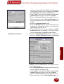
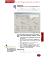
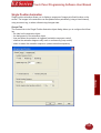
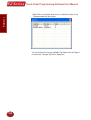
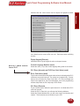
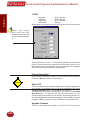
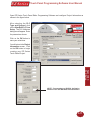
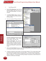
• Follow the onscreen prompts to load the software. (Installation
screens are shown, next page).
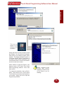
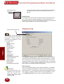
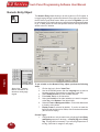
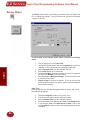
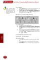
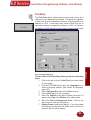
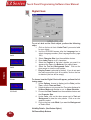
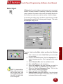
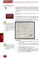
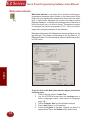
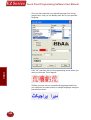
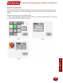
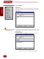
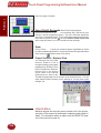
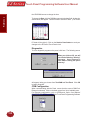
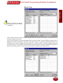
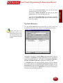
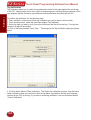
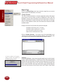
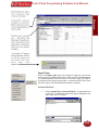
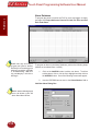
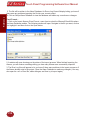
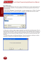
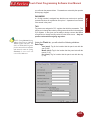
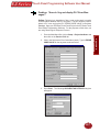
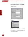
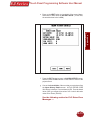
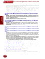
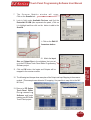
Installation Screens
12
Touch Panel Programming Software User Manual
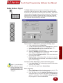
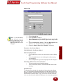
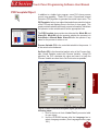
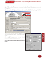
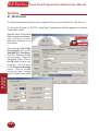
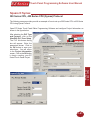
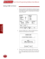
Introduction
Introduction
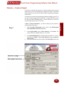
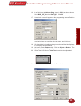
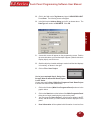
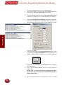
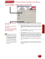
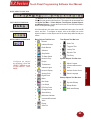
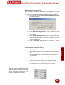
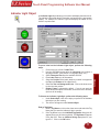
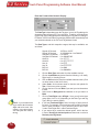
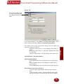
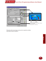
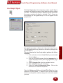
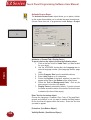
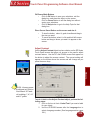
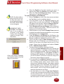
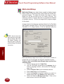
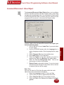
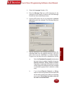
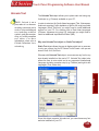
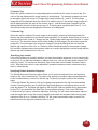
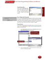
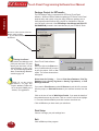
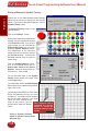
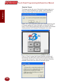
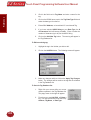
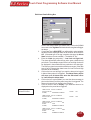
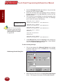
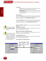
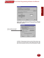
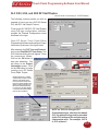
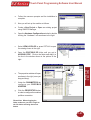
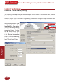
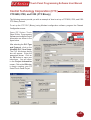
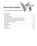
This icon will
appear on your
desktop after
installation.
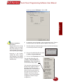
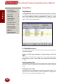
Simply follow the onscreen prompts to install
the software. You will select the destination
folder where your software program will be
installed. The default destination location is
C:\Program Files\EZ Series Touch Panel. If
you wish to select another destination, click
on the Browse button, choose the destination
and click on the Next > button.
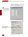
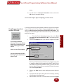
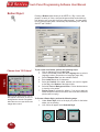
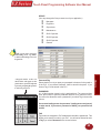
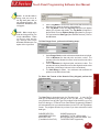
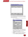
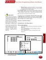
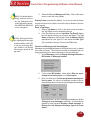
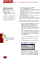
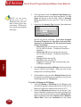
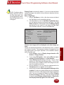
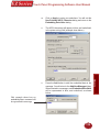
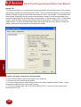
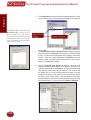
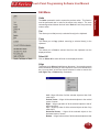
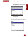
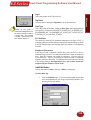
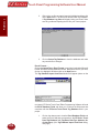
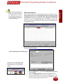
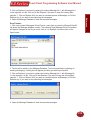
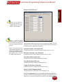
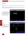
Select whether to install the English or the
Spanish version of EZ Series Touch Panel
Editor Programming Software. Click on the
Next> button.
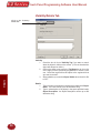
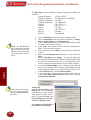
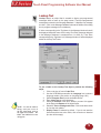
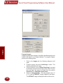
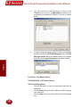
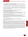
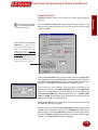
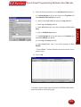
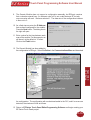
To complete the installation, click on Finish >
button. That’s all there is to it! The EZ Series
Touch Panel Icon shown above will appear on
your desktop. Simply click on it to open the
Programming Software!
NOTE: A different version
number may appear
depending on which version
of the software you are
installing.
13
Touch Panel Programming Software User Manual
Introduction
Once you’ve finished installing the software, the screen below should
appear. Open the software to view the EZLaunch Pad (see next page).
14
Touch Panel Programming Software User Manual
EZLaunch Pad
EZLaunch Pad is a convenient place to launch all EZAutomation software from one dialog box.
Distribution
EZLaunch Pad software is distributed with all EZAutomation software packages, such as EZ Series Touch Panel
Editor, EZ Series Text Panel, EZ Series PLC and EZMarquee String generator. The software is also available on
www.ezautomation.net as a free download.
Installation
To install this software please run the EZLaunchPadSetup.exe file. The software installs itself and places an icon
onto your desktop for your convenience.
Function
To use EZLaunch Pad software, click onto the EZLaunch Pad icon. The software opens up a dialog box that lists
all the installed and non-installed EZAutomation software on your computer. You may click on any of the installed
programs to launch that software. The non-installed software is also listed but cannot be used.
If you have multiple versions of any installed EZAutomation software, the Launch Pad lists all versions for your
convenience.
15
Introduction
Introduction
Overview
Introduction
Touch Panel Programming Software User Manual
This page intentionally left blank.
16
2
Tutorial
In this chapter....
— Configure a PLC
— Create a Project
Chapter 2
Touch Panel Programming Software User Manual
Tutorial — Configure PLC
For the purposes of this Tutorial, we will be using a DirectLogic® 05 Series
Programmable Logic Controller (PLC), with K-Sequence Protocol. To
configure the PLC we are using DirectSOFT® Programming Software. The
purpose of this part of the tutorial is to show you how to configure your PLC
to communicate with an EZ Series.
Connect the programming PC to the DL05 PLC. With DirectSOFT
Programming Software running on your PC, perform the following steps.
Enter the Ladder Logic as shown in the example below. These PLC
locations will be used by Tags that you will create in the EZ Series
Editor Programming Software.
2.
Save this program and transfer it to the PLC. Place the PLC in Run
Mode.*
3.
Exit DirectSOFT.
Tutorial
1.
For this tutorial, we will be connecting the panel to PLC Port 1 of a
DL05 (K-Sequence, 9600 Baud, Odd Parity). These are the settings
that will be used when setting up the panel communications.
You have now configured the PLC to communicate with an EZ Series
Project that you will create in the next section of this tutorial.
The following is a project tutorial. You’ve already configured your PLC to
work with the EZ Series project you will be creating in this section. Now
*The mode switch of all DirectLogic PLCs must be in (TERM) position in
order for the EZ Series to communicate with the PLC. Also, if it is necessary
for the Ladder Logic of the PLC to be protected by a Password, a multilevel password must used. Please refer to your PLC user manual to see
if your PLC supports this feature.
18
Touch Panel Programming Software User Manual
Tutorial — Create a Project
Let’s assume you have the programming software installed on your PC (if
you don’t, go back to page 12 and install now). Connect EZ Series to your
PC using the P/N EZ-PGMCBL cable. Connect EZ Series to your PLC
using the appropriate panel to PLC cable.
Introduction
we’ll take you through the process of creating a new project, placing
objects on the screen, and transferring a project to EZ Series. This should
help familiarize you with the EZ Series Editor Programming Software
environment.
In Step 1, Project Information, you will be setting up your project by
entering project information.
1.
From the Project Information screen, click on the Edit Program
OFF-LINE (Write to Panel Later) button.
2.
Under Project Name, type in Demo Project 1. Press Enter. The
primary EZ Series Program file has a “.ezt” suffix.
3.
Under Start Editing Screen, leave the screen number as 1. Click in
the field next to Name. Replace New Screen by typing in Numeric
Entry Screen.
Click on the DOWN arrow to the right of the Panel Type field to view
4.
19
Tutorial
Step 1
Touch Panel Programming Software User Manual
choices. Select the Panel Type you are using.
Enter Screen Number.
Tutorial
Type in “Numeric Entry
Screen” here.
Click on DOWN arrow to
view Panel Types and select
the Part Number/Model Type
you are using.
5.
Click on the DOWN arrow to the right of PLC Type and Protocol to
view the list. For the purpose of this Demo Program, select DirectLogic
K-Sequence. (We are using a DirectLogic DL05 PLC with K-Sequence
Protocol.)
6.
Click on the View/Edit PLC Com
Setup to edit the PLC Attributes.
Set the attributes to match those
in the DirectLogic K-Sequence
attributes dialog box shown to the
right. Click OK. (These settings
must match the PLC Com Port
settings. Check your PLC User
Manual for port settings for your
particular PLC.)
Click on DOWN arrow to
view PLC Type and Protocol
and select the type you are
using.
To set PLC Attributes, click
on this button. A dialog
box particular to the type
PLC and Protocol you have
selected will appear.
Step 1 is complete!
20
Touch Panel Programming Software User Manual
Step 2
The EZ Series Editor Programming Software working environment is shown
below. Tool bars provide easy access to all major programming functions
and features. The objects shown below represent the touch buttons and
displays that will be transferred to the panel and communicate with the PLC
when this tutorial is completed.
These are the four objects you are
about to configure in this tutorial.
21
Tutorial
This software option remembers
the last Data Type used, and
it becomes the Default Data
PROGRAMMING TIP: Before you begin placing objects on the programming
screen, click on Edit > Default Tag Data Type and select BCD_INT_16.
By selecting the default data type as BCD_INT_16 here, you won’t have to
select it later when configuring the tag details for the objects. Please note,
however, that if the data type for an object requires something other than
the default data type you have selected, it will show the required data type
(i.e., Discrete).
1. Click on Objects > Numeric Entry. The following screen will
appear.
2. Click on the box in front of Label Text to activate the object label.
Introduction
You are now ready for Step 2, Design Your Screens. In Step 2 we will
place 4 objects on the screen. You have already configured your PLC ladder
logic for this Demo Project in the first part of the tutorial.
Touch Panel Programming Software User Manual
In the field next to Label Text, type in Demo Numeric Entry as shown
Tutorial
3.
above.
4.
5.
Click in the field next to Tag Name and type in Numeric Entry.
Press Enter. The following screen will appear.
In the field next to Address String, type in V2002, as shown above.
Select BCD_INT_16 for the Data Type. Click OK.
PLEASE NOTE: If your
panel is connected to multiple
PLCs, use the Station Number
to address a specific PLC. For
example: 2–V2002 would
address the PLC Station
Number 2.
6. Click on the Protection tab. The following screen will appear.
7. Click on the box in front of Password Protect Object, and then click
22
Touch Panel Programming Software User Manual
on the box in front of Managers. Click on OK.
Introduction
Tutorial
NOTES ON RESIZING
AN OBJECT:
Drag the object to move, or drag
a handle to resize, the object.
The pointer changes to a fourway arrowhead (for moving), or
a two-way arrow (for resizing).
Dragging a side handle
changes the width or height
only; dragging a corner handle
changes the width and height
simultaneously.
8.
A cross-hair cursor will appear on the programming screen. Position
cross-hair where you want the object to appear, and click once.
9.
Grab the object by a handle and drag to resize it until the label displays
in its entirety, as shown to the right.
10. Now go to the Main Menu Bar and click
on Setup > Project Attributes.
11. Click on the Passwords tab. Under
From the Main Menu Bar, click
on Setup > Project Attributes >
Passwords to enter the password
for the Numeric Entry Object.
(You may have noticed that on the
Numeric Entry Object Protection
tab, there is a button that says
Edit Passwords. You can use this
button to enter the password for
the object, but in this tutorial, we
wanted to provide you with an
example of how Project Attribute
configuration relates to object
configuration.)
23
Touch Panel Programming Software User Manual
PASSWORD for the GROUP, Managers, type in “1234”. Click OK.
12. Next, we’ll create a Numeric Display object. Click on Objects >
Numeric Display. The following dialog box will appear.
13. Click on the box in front of Label Text to activate the object label.
14. In the field next to Label Text, type in Demo Numeric Display.
Tutorial
Please Note: Once the password
is entered for Managers, all
objects that you configure for
Protection at the “Manager”
level, will now require the
Password “1234”.
15. Click in the field next to Tag Name and type in NUMERIC DISPLAY.
Press Enter. The following screen will appear.
24
Touch Panel Programming Software User Manual
17. A cross-hair cursor will appear on the programming screen. Position
Introduction
16. In the field next to Address String, type in V2003, as shown above.
Select BCD_INT_16 as the Data Type. Click OK.
Tutorial
cross-hair where you want the object to appear, and click once.
18. Grab the object by a handle and drag to resize it until the label displays
in its entirety, as shown below.
19. Next, we’ll create a Button object. Click on Objects > Buttons. The
following dialog box will appear.
20. Click on the box in front of Label Text to activate the object label.
21. In the field next to Label Text, type in Demo Button.
25
Touch Panel Programming Software User Manual
22. Click in the field next to Tag Name and type in BUTTON OBJECT.
Press Enter. The following screen will appear.
23. In the field next to Address String, type in C0, as shown above. The
Data Type will remain as DISCRETE. Click OK.
Tutorial
24. A cross-hair cursor will appear on the programming screen. Position
where you want the object to appear (under the Numeric Entry object),
and click once.
25. Grab the object by a handle and drag to resize it until the label displays
in its entirety, as shown to the right.
26. Next, we’ll create an Indicator Light object. Click
on Objects > Indicator Lights. The following dialog
box will appear.
27. Click on the box in front of Label Text to activate the
object label.
28. In the field next to Label Text, type in Demo Indicator
Light as shown above.
26
Touch Panel Programming Software User Manual
30. In the field next to Address String, type in C1, as shown above. The
Data Type will remain as DISCRETE. Click OK.
Introduction
29. Click in the field next to Tag Name and type in INDICATOR LIGHT.
Press Enter. The following screen will appear.
Tutorial
31. A cross-hair cursor will appear on the programming screen. Position
the cross-hair where you want the object to appear (under the Numeric
Display object), and click once.
32. Grab the object by a handle and drag to resize it until the label displays
in its entirety, as shown to the right.
33. Click on File > Save Project.
You’ve just completed Step 2, Design Your
Screens! Now we will transfer Demo Project
1 to EZ Series.
You are now ready for Step 3, Write Your Program to Panel. Demo Project
1 should look similar to that shown below.
1.
Click on the 3 button (Write Your Program to Panel) as shown in the
graphic below.
2.
3.
Click on the Start button at the bottom of the Write Program to Panel
dialog box to begin transferring the project to the panel.
Your user program, Demo Project 1, should now be written to the EZ
Series, and the screen you have created should be displayed on the
panel.
4.
Panel Information will be updated with information it receives from
27
Touch Panel Programming Software User Manual
Step 3
5.
Tutorial
6.
7.
8.
28
establishing a link with the panel and the PLC.
To test the link, press the Demo Numeric Entry button on your EZ
Series screen. A popup keypad similar to the one shown below should
display.
Enter the Password “1234” on the keypad. Press Enter.
Another popup keypad similar to the one shown below will display.
Enter a number on the keypad by pressing the number keys. Press
Touch Panel Programming Software User Manual
9.
Press the Demo Button on your panel screen. It will change from
Off to On. The Demo Indicator Light should change from Off to On,
also.
Tutorial
The Panel to PLC Link will
display a green dot next to
the “Connected” message to
indicate that a link between the
panel and PLC is established.
Introduction
Enter. The keypad will disappear and the number you entered should
appear on the Demo Numeric Display on your panel screen.
Panel Information will display
the Total and Free Memory in
Bytes. It will also display the
Firmware Revision number
— the revision of the EZ Series
internal software.
You’ve just completed Step 3, Write Your Program to Panel!
29
Tutorial
Touch Panel Programming Software User Manual
You have now successfully configured a PLC, created a user program,
transferred it to the EZ Series and established communication between
the PLC and panel.
This simple tutorial has taken you through the major steps to creating a
working link between your application and an EZ Series. Of course, there
are almost unlimited capabilities for creating a program unique to your
application!
Changes are easy, too. Create your own Demo project based on this one,
adding color, password protection, and dynamic graphics, for instance.
EZ Series and EZ Series Editor Programming Software are practical,
versatile— and best of all — make it “EZ” for you to create a
dynamic interface for your application!
30
Project Setup
In this chapter....
— ON-LINE and OFF-LINE Projects
— Project Setup
— Entering Project Information (Step 1)
— Designing Screens (Step 2)
— Write Your Program to Panel (Step 3)
Chapter 3
3
Touch Panel Programming Software User Manual
Project Setup
Decide now if you want to work ON-LINE or OFFLINE...
You may create a new project on your PC by working off-line (not connected
to an EZ Series Touch Panel). You may also work on-line with an EZ Series
Touch Panel unit to make changes to an existing project.
Working off-line you may use EZ Series Touch Panel Editor Programming
Software to design your EZ Series Touch Panel unit in your office or home
— or even while traveling. Your project becomes as portable as your laptop,
and your EZ Series Touch Panel is not “down” while you are redesigning
or making modifications as your unique application needs grow or change.
Your project may be transferred to the EZ Series Touch Panel at any time.
The transfer function allows you to select a project to be transferred to the
Panel.
Project Setup
Working on-line is unique to EZ Series Touch Panels. Working in this mode
allows you to make quick fixes or design changes to an installed EZ Series
Touch Panel and its existing program. You can eliminate a step or two
and save time by transferring these changes directly to the current opened
screen. Now you can see the effect of the screen design changes you have
made immediately, eliminating the traditional “edit-compile-download” cycle.
Simply click on Save Screen or Save Project and all changes on the current
opened screen will immediately be saved in the EZ Series Touch Panel.
Most users will employ both methods at one time or another, but whether
working off-line or on-line — you will certainly appreciate the versatility
and accessibility provided by EZ Series Touch Panel and its easy-to-use
programming software.
The next section takes you through the steps necessary to create a project
and transfer it to EZ Series Touch Panel. EZ Series Touch Panel Editor
Programming Software simplifies this process by using Windows-based
architecture and lots of popup and pull down selections that guide you
through the process to quickly build your screens and get you up and
running in no time at all!
We recommend you go through the tutorial beginning on page 17
of this manual. You’ll see how easy it is to get up and running!
32
Touch Panel Programming Software User Manual
Step 1 Project Information
Edit Program OFF-LINE
(Write to Panel Later)
Under SELECT ACTION, click on one of the three “working mode buttons.”
If you want to work off-line (not connected to an EZ Series Touch Panel),
click on the button labeled Edit Program OFF-LINE (Write to Panel Later).
You will use this mode when creating a new project.
1. From Project Information screen, click on the Edit Program
OFF-LINE (Write to Panel Later) button.
NOTE: If you change your mind and click on another SELECT
ACTION button, a “confirm
action” message will appear, just
to make sure that this is what
you intended to do. Click on Yes
or No.
2. Click on the Browse button if you want to navigate to another
Directory or Folder where you will store your project. If you want
to accept the default folder (where EZ Series Touch Panel Editor
Programming Software resides), just enter the name of your new
project in the empty field under Project Name.
3. Under Start Editing Screen, leave the screen number as 1. Click
in the field next to Name to highlight New Screen. Replace this
by typing in the name of your first screen. If you haven’t decided
33
Project Setup
SELECT ACTION
Touch Panel Programming Software User Manual
on a name, just leave it as is, you can change it later.
4. Click on the DOWN arrow to the right of the Panel Type field to
view choices. Select the Panel Type you are using.
5. Click on the DOWN arrow to the right of PLC Type and Protocol to
view the list. Select the PLC Type and Protocol you are using.
6. Click on the View/Edit PLC COM Setup to edit the PLC Attributes.
A dialog box will appear that is particular to the type of PLC you
have selected in the previous step. Set the attributes to match
Project Setup
your PLC. Click OK.
7. You should now be back to the Project Information screen. Check
to ensure that your Ethernet/COM Port is set to match your PC
(COM1, COM2, COM3 or COM4), or, if you want an Ethernet
connection, select Ethernet. A Select Panel button will appear
(as shown below).
8. Click on the Select Panel button to begin Ethernet
configuration. Please note: For help with Ethernet configuration refer to
the Ethernet Option Card Manual, P/N EZP-ETHERNET-M, or
Ethernet Help topics.
34
9. When finished with Ethernet Configuration, click on the OK
Touch Panel Programming Software User Manual
button.
10. You will return to the Project Information screen, click on the
OK button to accept all settings.
You are now ready to begin configuring your first screen.
Read Program from Panel
and Edit OFF-LINE
If you are connected to a panel and want to transfer a project from the panel
to your EZ Series Touch Panel Editor Programming Software for editing,
click on the Read Program from Panel and Edit OFF-LINE button. Any
changes you make to the project will not take effect until you write the edited
project to your panel.
1. From the Project Information screen, click on the Read
Program from Panel and Edit OFF-LINE. The following screen
will appear.
2. Click on the Browse button if you want to navigate to another
If not using the default
directory, click on the Browse
button to go to directory and
folder where project will be
stored.
Select or enter Project Name.
Click on Start button to Start
Reading Project from Panel or
Abort to quit.
Directory or Folder where you will store your program. If you want
to accept the default folder (usually where the EZ Series Touch
Panel Editor Programming Software resides), just enter the name
that you desire for the project you are about to Read in the empty
field under Project Name.
3. Click on the Start button to start reading the project from the
panel.
4. A progress bar will appear, along with a text message, showing
you the status of the panel read.
5. When finished, click OK. You will be taken back to the Project
35
Project Setup
Touch Panel Programming Software User Manual
The message “Project
downloaded successfully” will
appear when the program has
finished downloading.
Click on OK to exit
screen.
Project Setup
Information Screen. Notice that the project name entered now
appears under Project Name in this screen.
6. Under Start Editing Screen, the Name and Number of Screen
number 1 will appear. If you want to begin editing another screen,
click on the down arrow next to Name or Number and select.
7. Click on the OK button to begin editing. You will go to the EZ
Series Touch Panel Editor Main Programming Screen. You are
now ready to edit the selected screen.
Edit Program ON-LINE
The third choice available is to make changes to the project while online.
Click on the button labeled, Edit Program ON-LINE. The changes are
effective each time Save Screen or Save Project is selected, reducing
downtime. Click on Save Screen or Save Project and the changes will
appear on the panel screen immediately. This is recommended when you
need to make changes quickly to an existing user program without shutting
down the system.
1. From the Project Information screen, click on the button
labeled, Edit Program ON-LINE. The Panel Type, PLC Type,
and Firmware Revision of the panel will soon display.
2. Under Start Editing Screen, screen Number 1 will appear with
that screen’s Name. If you want to begin editing a screen other
than Number 1, click on the down arrow next to the Number field
or the down arrow next to the Name field to select the screen you
want to edit.
36
3. Click on OK. The screen you have selected will open on the
main programming screen for you to make changes.
4. Click on Save Screen to download changes to the screen
immediately. Click on Save Project to transfer all changes,
including project attributes and databases. They will be
immediately downloaded to the panel.
Touch Panel Programming Software User Manual
A QUICK REVIEW for “ENTER PROJECT INFORMATION”
Click on the Help Button at anytime for help.
Under ENTER PROJECT INFORMATION you will perform all or some of the
following actions (depending upon the working mode you have selected):
1. Project Location will default to the directory where the EZPanel
Software program is stored. If your project resides in another
location, click on the Browse button to navigate to a different
folder.
Click on Exit to quit without saving
your selections, or click on OK to
save and begin editing.
2. Under Project Name, click on the down arrow to view saved
projects or enter the new project name. 3. Start Editing Screen allows you to select the screen that you
want to begin editing. To have the project open to the screen you
wish to edit, click on the down arrow to select the Name or the
Number of the screen. If it is a new project, the screen will default
to screen 1 with <New Screen> in the Name field. Replace this
with whatever name you wish or wait until later and rename.
Note: Panels with an option
card installed will have an “C, D,
E, H, M, P, T, or U” on the end of
the model part number to indicate
this. The program loader doesn’t
list these under Panel Type, so
just select the model part number
without the “C, D, E, H, M, P,
T, or U” that is closest to your
panel part number. See step 8,
next page.
4. The field Panel Type, allows you to select or change your panel
type.
If you are connected to the panel (editing project on-line), the
Firmware Revision of the panel’s internal software will be
displayed.
37
Project Setup
Click on Clear to clear your entries
and start over.
Touch Panel Programming Software User Manual
Please NOTE:
PLC compatibility is always being
updated. If you don’t see your
type PLC and protocol, visit our
website at www.EZAutomation.
net to see if your PLC driver is
now available to download.
5. PLC Type and Protocol allows you to further define your project
by selecting the PLC used in your application and the protocol
it uses. Click on the down arrow for a list of the available PLC
types.
6. Click on the View/Edit PLC COM Setup button to display the
PLC Attributes. The attributes screen particular to the PLC and
Protocol type you have selected will appear. You may change
attributes from this screen.
7. If you are using a Think-n-Do Map File for Automation Direct,
click on the Browse button to go to the directory or folder where
the map file resides.
The map file is simply a text delimited file that resides in any
Think-n-Do project. The EZ Series Touch Panel Editor is set up
to pull tag names from your Think-n-Do project. This frees the
user from having to remember these tag names.
Project Setup
The map file will load into the project’s Tag Database. Tag
Database Log View will open if there are problems. You may
correct any problems from within the Think-N-Do map file or the
Tag Database.
8. If you are using an EZ Series Touch Panel unit with an Option
Card installed, the Model Part Numbers for your unit have a “C,
D, E, H, M, P, T, or U” on the end to designate “C” for Mitsubishi
CC Link, “D” for Generic DeviceNet I/O, “E” for Generic Ethernet
I/P, “H” for Allen Bradley Data Highway Plus/Remote I/O, “M”
for Modicon Modbus Plus, “P” for Siemens Profibus, “T” for
Modicon Modbus TCP/IP, “U” for Universal Ethernet (Ethernet/
IP, DF1 over Ethernet, Modbus TCP/IP, and GE SRTP. These
option card designation letters do not appear on all model types
where an option card is available when you are selecting your
Panel Type on the Project Information screen. Just click on
the model part number without the “C, D, E, H, M, P, T, or
U” on the end that matches your panel size. In other words,
the program loader doesn’t see any differences in panel type
between an EZ-S8C-FH (with A-B DH+ option card installed) and
an EZ-S8C-F, so you will select ALL, 8” Color, 640x480. Any
differences between the units are configured when you select
the PLC Type and Protocol as Mitsubishi CC Link, Generic
DeviceNet I/O, Generic Ethernet/IP, Allen-Bradley Remote I/O,
Modicon Modbus Plus, Siemens Profibus, Modicon Modbus
TCP/IP, or Universal Ethernet (Ethernet/IP, DF1 over Ethernet,
Modbus TCP/IP, GE SRTP).
Once you click on OK, the project will open to the screen you have selected
and you may begin creating or editing your project!
38
Touch Panel Programming Software User Manual
Step 2 Design Your Screens
Your project information has been entered and you are now ready to begin
designing your screens. Remember that you can go back to step one and
change project information, if necessary. Just click on the 1 button on the
3 Easy Steps Tool Bar, shown to the left.
For more information on the Main Programming Screen, see page
144.
Project Setup
1. Click on the 2 button, Design Your Screens, and the following
screen will appear.
2. Double click on one of the screens in the Screen List to open it,
or enter a new screen number and name and click on the Open
button.
39
Touch Panel Programming Software User Manual
Screens — Explorer View
3. You may also use the Screen Explorer view to navigate between
screens. Double click on an existing screen listed in the Explorer
window that you want to edit. The Main Programming Screen
will open to the selected screen. You can easily switch between
screens you are working on, to copy, paste, make changes,
etc.
4. Right click the mouse at any time while
designing your screens to access the menu
shown to the right
Some of the screen design features available
to you are:
Project Setup
40
•
•
•
•
•
•
•
•
•
•
•
Program labels in up to 9 languages
Popup Keypad that allows you to enter data
Vector-based graphics for easy sizing,
displayed in up to 128 colors
Graphical trending
PID loop tune face plates
Recipe download
Thumbwheel interface
Radio buttons
Analog clocks
Meters, switches and lamps
Symbol Factory® library of over 4,000 factory objects
5. You are now ready to begin configuring objects.
Touch Panel Programming Software User Manual
Step 3 Write Your Program to Panel
Click on the button for Step 3, Write Your Program to Panel. Check to
ensure that “Ethernet/COM Port” matches the port that is connected to
your panel and click on the Start button. Read the information below to
learn more about the “Write Program to Panel” screen.
Before Panel Write....
Project Information: Provides
information about the current
project you are about to
transfer to the panel.
Panel to PLC Link will display “Not
Connected” until download is completed.
Project Setup
DON’T LOSE AN EXISTING PROGRAM! If
you’re not sure of the changes you have
made, save the existing program to a
different project name from the one you are
about to transfer to the panel before you
click on the Start button.
Press the Start Button, the program will
be transferred to the panel.
Panel Write Completed....
If the panel is connected to a PLC, the
Panel to PLC Link will display a green
dot next to the “Connected” message to
indicate that a link is established.
Panel Information will display the
Total and Free Memory in Bytes. (Most
models allow you to increase memory
by adding another RAM card.) It will
also display the Firmware Revision
number — the revision of the EZ Series
Touch Panel internal firmware.
41
Touch Panel Programming Software User Manual
Project Setup
EZ Series Touch Panel is shipped with a bitmap
program installed. The image shown above will
display on the EZ Series Touch Panel screen upon
initial power-up. The first project you transfer to the
panel will replace this bitmap program!
42
Objects
In this chapter you will be shown how to create....
— Buttons
— Indicator Buttons
— Radio Buttons
— Switches
— Step Switch
— Tri-state Switch
— Numeric Entry
— Recipe
— Thumbwheel
— Indicator Lights
— Numeric Display
— Text Objects
— Clock Object
— Meter
— Bar Graphs
— Line Graph
— PID Face Plate
— Change Screen
— Alarm History
— System Objects
— Multi-state Indicator
— Bitmap Objects
— Increment/Decrement Value
— Report
— View File
Chapter 4
— Unicode
Objects
4
Touch Panel Programming Software User Manual
Objects Menu
In PLC-based control, the PLC performs the following control sequence
continuously: reads inputs, solves control logic (ladder logic), writes values,
and sets/resets outputs. The state of inputs and outputs is kept as bits in a
data table. The data table is typically organized in words, with each word
having 16 bits. Data values, such as parts count, are also kept as words
in the data table.
EZ Series Touch Panel provides direct access to the bits and words of the
PLC data table, without going through I/O modules. The panel provides this
access through its tags. EZ Series Touch Panel has tags that are mapped
to the PLC data table. The mapping between panel tags and PLC data
tables is user-defined through a simple dialog box. EZ Series Touch Panel
objects allow you to set/reset bits and to read/write from the PLC data table
through the panel tags.
Objects
For example, when a panel button object is pressed, it sets a panel tag.
The panel transfers the state of this tag to the mapped bit in the PLC data
table. Similarly, the PLC may set an output bit that turns on a pilot light
on the panel.
Please Note: Panel Tags may be internal (not mapped to the PLC) or external (mapped to the PLC).
Panel Tags may be:
•
•
•
•
•
•
•
Discrete
16-bit (Signed/Unsigned)
32-bit (Signed/Unsigned)
16-bit BCD
32-bit BCD
32-bit Floating Point
ASCII String
IMPORTANT! To learn all the steps to configuring an
object, read the instructions for the first object, Button
Object, in its entirety. It will take you through each step in
detail, explaining all the variables and choices. Because
the objects share many common features, they are not
repeated for each object. Any features that are unique to
a particular object are explained in its own section. We
recommend that you try out the tutorial, beginning on page
14, to learn the steps involved in creating an EZ Series
Touch Panel project.
44
Touch Panel Programming Software User Manual
BASIC OBJECTS TOOL BAR
TEXT OBJECTS TOOL BAR
SYSTEM OBJECTS TOOL BAR
BITMAP OBJECTS TOOL BAR
Configure an object
by selecting it from the
OBJECT MENU or one
of the OBJECT TOOL
BARS
The Objects menu allows you to choose from several predefined objects.
Objects provide generic panel functions. The objects can be accessed from
the Object Tool Bars — Basic Objects, Text Objects, System Objects,
and Bitmap Objects — shown above and to the left, and the Objects Menu
shown on the preceding page.
All of the objects in this menu have user-defined frame types, line and fill
colors, and text. To configure an object, click on the object icon on the
object tool bars or on the object name in the menu drop down list with your
mouse.
Basic Objects Tool Bar Icon
•
•
Buttons
Text Objects Tool Bar Icon
Tri-State Switch
•
•
•
•
•
Numeric Entry
System Objects Tool Bar Icon
Recipe
•
•
Indicator Buttons
Radio Buttons
Switches
Step Switch
Thumbwheel
Indicator Lights
Numeric Display
Analog Clock
Static Text
Triggered Text
Lookup Text
Dynamic Text
Text Entry
Adjust Contrast
Increment/Decrement
Hour
Activate Screen Saver
Select Language
•
•
Digital Clock
Meter
Bar Graph
Line Graph
PID Face Place
Bitmap Objects Tool Bar Icon
•
•
•
Dynamic Bitmap
Bitmap Button
Multi-state Bitmap
Change Screen
Alarm History
Multi-state Indicator
Increment/Decrement
Value
Report
View File
45
Objects
• • • •
• • • • • • • • • • • • • • • • • Touch Panel Programming Software User Manual
Button Object
Pressing a Button object allows you to WRITE to a Tag. It can be displayed in a variety of colors, sizes and shapes and has a simulation option (allowing you to see how it will look when pressed). You may select
from 5 types of button states: Momentary ON, Momentary OFF, Set ON,
Set OFF and TOGGLE.
Objects
Choose from 128 Colors!
Click on the down arrow next to
the default color block for text or
background to view the color palette.
Move the cursor over your choice and
simply click to select.
46
To put a Label on a Button, perform the following steps:
1. Click on the box in front of Label Text.
2. Use the UP/DOWN arrows after the Language box to select a
language number. (See section on Language, page 198.)
3. Select Character Size from the available choices.
4. Enter Label Text up to 40 characters.
5. Select the Position of the label, whether you want it to appear
at the Top or the Bottom of the object frame.
6. Select the Text and Background Color. Click on the down arrow
to view the color palette.
7. Display Frame is selected by default. If you do not want the
frame around the button to be visible, click on the box to deselect
(the box will be empty).
To Choose a Button Style, perform the following steps:
1. Under Select Style, click on the style you prefer for the button
object you are creating.
2. Your choice will appear under Selected Style.
Touch Panel Programming Software User Manual
Enter a Tag Name:
1. Enter a Tag Name or click on the down arrow and select the Tag
Name that you want the button to correspond to.
2. If the Tag Name is new, the Add New Tag Details dialog box will
appear where you will map the tag. The Tag Name will appear
in the first field. Enter an Address String appropriate for your
type PLC. Click on the OK button.
For more information about Tags, see
Tag Database, page 176.
NOTE: If your panel is
connected to multiple PLCs, use
the Station Number to address
a specific PLC. For example:
2–V2002 would address the
PLC Station Number 2.
NOTE: If you select Momentary
ON or Momentary OFF, the
PLC must set bit to proper
state on powerup. This must
be done when programming
PLC Logic.
For each object, you may
program the text to display in up
to 9 Languages! (See Language
section on page 198.)
Select from the following Actuator Types:
Actuator Type determines how the tag will be controlled. NOTE: If
you have assigned Password Protection for this object and select
Momentary On or Momentary Off, the protection feature is disabled
with this actuator type.
•
•
•
•
•
Momentary On will turn the tag on for as long as you touch
the button. (Password Protection is disabled.)
Momentary Off will turn the tag off for as long as you touch
the button. (Password Protection is disabled.)
Set On will latch the tag ON.
Set Off will latch the tag OFF.
Toggle will change the state of the tag every time the button is
pressed.
Enter On/Off Text:
Here you will enter the Text that will appear within the object, and control
how that text will appear.
1. Select the Language number (1–9) for the On/Off Text.
2. Type in what you want to appear within the button for the On
Text and for the Off Text (i.e., you might want to place the words
STOP and RUN inside the buttons, instead of Off and On).
3. Select Character Size from the available choices
4. Select the Color of the Text and the Color of the
Background.
5. If you want the Text or the Background to Blink, click on the
box below Blink to place a check mark indicating that the option
is enabled.
OK/Cancel/Help Buttons
•
Click on OK button to save your selections and exit the dialog
box.
•
Click on Cancel button to exit the dialog box without saving
your selections.
•
Click on Help button to go to the Help Topic for that dialog box.
Place Button on the screen and size it.
•
To size the button, grab a handle and drag it to the size you
want.
47
Objects
Hello...
Hola...
Guten Tag...
NOTE: To edit the Address String, with your cursor in the
Tag Name field, click on the right mouse button. The Edit
Tag Details screen will appear.
Touch Panel Programming Software User Manual
Grab a handle with
your mouse
•
To move the button, select it, click and hold left mouse button
and drag it to the area of the screen where you want it to
appear.
Simulate Press
To Simulate Press, double click the object to bring up the object dialog
box. (You may have to drag the dialog box to see the object on the
programming screen.) Click on the Simulate Press button to see how the
button object will display on the screen when pressed.
Objects
Click on the Protection Tab
The following touch objects allow
you to enable protection and assign
passwords to allow a group or
individual (user-defined) to have
access to that object:
Buttons
Indicator Buttons
Switches
Step Switches
Tri-State Switches
Numeric Entry
Recipe
Thumbwheel
Text Entry
Change Screen
Alarm History
Increment/Decrement Hour
Activate Screen Saver
Adjust Contrast
Select Language
Bitmap Button
Increment/Decrement Value
Important!
Password Protection is not
intended to work with objects
when the actuator type
selected is Momentary On and
Momentary Off.
48
Protection Tab
The Password Protect Object feature allows you to prevent unauthorized users from accessing certain objects and their functions. This feature is useful when several people will be using EZ Series Touch Panel
to perform different tasks, such as, changing initial values, or monitoring
system status. To enable password protection for the object, click in the
box in front of the groups you wish to allow access.
Edit Passwords
There are eight groups that you may assign Passwords to. Passwords
allow you to implement restrictions on who can use the password protected objects (e.g., to make system or internal panel adjustments, enter
text or values, or control a machine function in your application). Click
on the Edit Passwords button to setup or change the passwords.
Touch Panel Programming Software User Manual
GROUP
(You may change the Group names to suit your application.)
✔
✔
✔
✔
✔
✔
✔
✔
Managers
Engineers
Supervisors
Maintenance
Shift 1 Operator
Shift 2 Operator
Shift 3 Operator
General
NOTE: If you enter a password
with leading zeroes, e.g., 00003
or 00533, the leading zeroes will
be ignored!
Password/Tag
Select whether or not you want your password to be stored in the panel or
in the PLC. If you choose Password, it will be stored in the panel. If you
choose Tag, it will be stored in the PLC.
PASSWORD
A 1–10 digit number (numeric only) is assigned here. The user must then
enter this number to perform protected functions for a particular Group.
You will not be allowed to enter a password if you select Tag in the second
column.
Do not enter leading zeroes in a password. Leading zeroes are ignored.
In other words, if you enter a password of 00456, your password will
be 456.
TAG
Tag names are assigned to PLC addresses that hold the passwords. This
allows you to store the codes in your PLC. You will not be allowed to enter
a Tag if you select Password in the second column.
49
Objects
A keypad similar to the one
shown below will appear on the
panel when a protected objected
is pressed, prompting the operator
to enter the password.
Touch Panel Programming Software User Manual
Visibility/Details Tab
Click on the Visibility/
Details Tab
Objects
Visibility
1. Check the box in front of Visibility Tag if you want to control
when the object is visible on the screen. (If it is not checked the
object will always be visible.)
2. Click on the down arrow next to the Tag Name box to view a list
of the tags you have previously programmed or create a new
one. Select the tag that links the object to the register bit that
you want to control it.
3. Select whether you want the Object Visible when the bit is ON
or OFF.
Details
1. Type in a name for the object in the space provided under Object
Name. The name can be up to 40 characters long.
2. Type in a description of the object in the space provided under
Object Description. An Object Description can be up to 400
characters long.
50
Touch Panel Programming Software User Manual
Indicator Button Object
An Indicator Button combines a regular button with an indicator light. It
allows you to perform a WRITE operation to one bit and a READ operation from a second discrete location. The state of that READ location
determines whether the button is displayed in the ON or OFF mode. You
may choose to make the READ and WRITE location the same.
To put a Label on an Indicator Button, perform the following steps:
To Choose an Indicator Button Style, perform the following steps:
1. Under Select Style, click on the style you prefer for the button
object you are creating.
2. Your choice will appear under Selected Style.
NOTE: To edit the Address
String, with your cursor in
the Tag Name field, click on
the right mouse button. The
Edit Tag Details screen will
appear.
Enter a Tag Name:
1. Enter a Tag Name or click on the down arrow and select the
Tag Name that you want the Indicator button and the Indicator to
correspond to.
2. If the Tag Name is new, the Add New Tag Details dialog box
will appear where you will enter tag details. The Tag Name will
51
Objects
1. Click on the box in front of Label Text.
2. Use the UP/DOWN arrows after the Language box to select a
language number. (See section on Language, page 198.)
3. Select Character Size from the available choices.
4. Enter Label Text up to 40 characters.
5. Select the Position of the label, whether you want it to appear
at the Top or the Bottom of the object frame.
6. Select the Text and Background Color. Click on the down arrow
to view the color palette.
7. Display Frame is selected by default. If you do not want the
frame around the button to be visible, click on the box to deselect
(the box will be empty).
Touch Panel Programming Software User Manual
appear in the first field. Enter an Address String appropriate for
your type PLC. Click on the OK button.
Note: If you have assigned
Password Protection for this
object and select Momentary On
or Momentary Off, the protection
feature will not be enabled.
Also, if you select Momentary
ON or Momentary OFF, the
PLC must set bit to proper state
on powerup. This must be done
when programming PLC Logic.
Select from the following Actuator Types: Actuator Type determines
how the tag will be controlled.
•
Momentary On will turn the tag on for as long as you touch the button. (Password Protection is disabled.)
•
Momentary Off will turn the tag off for as long as you touch the button. (Password Protection is disabled.)
•
Set On will latch the tag ON.
•
Set Off will latch the tag OFF.
•
Toggle will change the state of the tag every time the button is pressed.
Enter On/Off Text: Here you will enter the Text that will appear within the
object, and control how that text will appear.
1. Select the Language number (1–9) for the On/Off Text.
2. Type in what you want to appear within the button for the On Text
and for the Off Text (i.e., you might want to place the words STOP
and RUN inside the buttons, instead of Off and On).
3. Select Character Size from the available choices
4. Select the Color of the Text and the Color of the Background.
5. If you want the Text or the Background to Blink, click on the
box below Blink to place a check mark indicating that the option
is enabled.
Protection (See Button Object.)
Visibility/Details (See Button Object.)
Objects
OK/Cancel/Help Buttons
•
Click on OK button to save your selections and exit the dialog
box.
•
Click on Cancel button to exit the dialog box without saving
your selections.
•
Click on Help button to go to the Help Topic for that dialog box.
Place Indicator Button on the screen and size it.
•
To size the Indicator button, select it, grab a handle and drag.
•
To move the button, select it, click and hold left mouse button
and drag it to where you want it to appear on the screen.
Simulate Press
To Simulate Press, double click the object to bring up the object dialog
box. (You may have to drag the dialog box to one side to see the object
on the programming screen.) Click on the Simulate Press button to see
how the button object will display on the screen when pressed.
52
Touch Panel Programming Software User Manual
Radio Buttons Object
The Radio Button object has a maximum of 8 buttons, however, only
one can be on at any given time. When a button is pressed it releases
any button that may be ON, and becomes the active button. Each button
controls a bit and is assigned an area of the touchscreen. Radio buttons
can have from 2 to 8 buttons. Please note that no more than 6 vertical
buttons can be used for the regular 6-inch panels, slim bezels with 192
(16 x 12) touch cells can have up to 8 buttons.
NOTE: To edit the Address
String, with your cursor in
the Tag Name field, click on
the right mouse button. The
Edit Tag Details screen
will appear.
To Choose a Radio Button Style, perform the following steps:
1. Under Select Style, click on the style you prefer for the button
object you are creating.
2. Your choice will appear under Selected Style.
Enter a Tag Name:
1. Enter a Tag Name or click on the down arrow and select the Tag
Name that you want to button to correspond to.
2. If the Tag Name is new, the Add New Tag Details dialog box
will appear where you will enter tag details. The Tag Name will
appear in the first field. Enter an Address String appropriate
for your type PLC. Click on the OK button.
53
Objects
To put a Label on a Radio Button, perform the following steps:
1. Click on the box in front of Label Text.
2. Use the UP/DOWN arrows after the Language box to select a
language number. (See section on Language, page 198.)
3. Select Character Size from the available choices.
4. Enter Label Text up to 40 characters.
5. Select the Position of the label, whether you want it to appear
at the Top or the Bottom of the object frame.
6. Select the Text and Background Color. Click on the down arrow
to view the color palette.
7. Display Frame is selected by default. If you do not want the
frame around the button to be visible, click on the box to deselect
(the box will be empty).
Touch Panel Programming Software User Manual
NOTE: This object can use a signed or unsigned Data Type. Button 1 = Bit 0
in assigned tag. Button 8 = Bit 7 in assigned tag. Bits 9 to 15 are not used.
Select Number of Buttons:
1. Click on the UP or DOWN arrow to select the number of radio
buttons. You may choose from 2 to 8 buttons. (You may only
have 6 buttons for 6-inch panels with 48 touch cells.)
Enter On/Off Text:
Text size and color are programmed under the General Tab. These
characteristics will be implemented for all of the inside button text.
1. Select the Character Size for the On Text and the Off Text.
2. Choose the Color of the Text by clicking on the arrow button to
view the color palette. Move the cursor over the color you want
and click to select.
3. Select whether or not the Text will Blink.
4. Next, select the Background Color of the button and whether
or not it will Blink.
5. Each Radio Button (from 2 to 8) may contain different text and
a different language. Click on the Button #1 tab.
Objects
Click on the Button #1 Tab
to edit Language and On/Off
Text.
6. Choose the Language number (1–9) and type in the text as you
want it to appear within that button when ON and when OFF (i.e.,
you might want to place the words STOP and RUN inside the
buttons, instead of Off and On).
Remember that the other universal characteristics for the
button text and background have been chosen under the
General Tab (character size, color, etc.).
54
Touch Panel Programming Software User Manual
Protection (See Button Object.)
Visibility/Details (See Button Object.)
OK/Cancel/Help Buttons
•
Click on OK button to save your selections and exit the dialog
box.
•
Click on Cancel button to exit the dialog box without saving
your selections.
•
Click on Help button to go to the Help Topic for that dialog box.
Place Radio Button on the screen and size it.
•
To size the button, select it, grab a handle and drag.
•
To move the button, select it, click and hold left mouse button
and drag to where you want it to appear on the screen.
Simulate Press
To Simulate Press, double click the object to bring up the object dialog
box. (You may have to drag the dialog box to see the object on the
programming screen.) Select the tab of the button you want to simulate.
Click on the Simulate Press button to see how the button object will display on the screen when pressed.
There are several types of Switch objects that you may place on the EZ
Series Touch Panel screen. They simulate mechanical switches of the
same type, e.g.; Throw Switch, Selector Switch, Slide Switch, Toggle
Switch, etc.
Objects
55
Touch Panel Programming Software User Manual
Switch Object
To put a Label on a Switch, perform the following steps:
1. Click on the box in front of Label Text.
2. Use the UP/DOWN arrows after the Language box to select a
language number. (See section on Language, page 198.)
Objects
3. Select Character Size from the available choices.
4. Enter Label Text up to 40 characters.
5. Select the Position of the label, whether you want it to appear
at the Top or the Bottom of the object frame.
6. Select the Text and Background Color. Click on the down
arrow to view the color palette.
7. Display Frame is selected by default. If you do not want the
frame around the switch to be visible, click on the box to deselect
(the box will be empty).
To Choose a Switch Style, perform the following steps:
1. Under Select Style, click on the style you prefer for the switch
object you are creating.
2. Your choice will appear under Selected Style.
NOTE: To edit the Address
String, with your cursor in
the Tag Name field, click on
the right mouse button. The
Edit Tag Details screen
will appear.
56
Enter a Tag Name:
1. Enter a Tag Name or click on the down arrow and select the Tag
Name that you want the switch to correspond to.
2. If the Tag Name is new, the Add New Tag Details dialog box
will appear where you will enter tag details. The Tag Name will
appear in the first field. Enter an Address String appropriate
for your type PLC .Click on the OK button.
Select the Switch Background color by clicking on the DOWN arrow and
selecting a color from the palette.
Touch Panel Programming Software User Manual
NOTE: If you select Momentary
ON or Momentary OFF, the
PLC must set bit to proper
state on powerup. This must
be done when programming
PLC Logic.
Select from the following Actuator Types:
Actuator Type determines how the tag will be controlled. If you have
assigned Password Protection for this object and select Momentary
On or Momentary Off, the protection feature will not be enabled with
this actuator type.
•
Momentary On will turn the tag on for as long as you touch the
switch. (Password Protection is disabled.)
•
Momentary Off will turn the tag off for as long as you touch the
switch. (Password Protection is disabled.)
•
Set On will latch the tag ON.
•
Set Off will latch the tag OFF.
•
Toggle will change the state of the tag every time the switch is
pressed.
Enter On/Off Text:
Here you will enter the Text that will appear within the object, and control
how that text will appear.
1. Select the Language number (1–9) for the On/Off Text.
2. Type in what you want to appear within the switch for the On Text
and for the Off Text (i.e., you might want to place the words STOP
and RUN inside the switches, instead of Off and On).
3. Select Character Size from the available choices
4. Select the Color of the On Text and the Color of the Off Text.
5. If you want the Text to Blink, click on the box below Blink to
place a check mark indicating that the option is enabled.
Protection (See Button Object.)
Visibility/Details (See Button Object.)
Place Switch on the screen and size it.
•
To size a switch, click on it to select, grab a handle with the
mouse and drag to the size you want.
•
To move the switch, select it, click and hold left mouse button,
and drag to where you want it to appear on the screen.
57
Objects
OK/Cancel/Help Buttons
•
Click on OK button to save your selections and exit the dialog
box.
•
Click on Cancel button to exit the dialog box without saving
your selections.
•
Click on Help button to go to the Help Topic for that dialog box.
Touch Panel Programming Software User Manual
Step Switch Object
The Step Switch object simulates a Mechanical Step Switch on the panel. It
allows you to simultaneously monitor and control two, three, or four different
bits and display ON and OFF text for each bit. Each time the Step Switch
is pressed, each bit will be cycled one at a time from OFF to ON with only
one bit ON at a time.
Objects
To put a Label on a Switch, perform the following steps:
1. Click on the box in front of Label Text.
2. Use the UP/DOWN arrows after the Language box to select a
language number. (See section on Language, page 198.)
3. Select Character Size from the available choices.
4. Enter Label Text up to 40 characters.
5. Select the Position of the label, whether you want it to appear
at the Top or the Bottom of the object frame.
6. Select the Text and Background Color. Click on the down arrow
to view the color palette.
7. Display Frame is selected by default. If you do not want the
frame around the switch to be visible, click on the box to deselect
(the box will be empty).
To Choose a Step Switch Style, perform the following steps:
1. Under Select Style, click on the style you prefer for the button
object you are creating.
2. Your choice will appear under Selected Style.
Choose the Number of Steps (from 1 to 4) in the process or application
that you want your switch to control. Enter the number of steps or click on
the up/down arrows to select.
58
Touch Panel Programming Software User Manual
Step #1 Tab
NOTE: To edit the Address
String, with your cursor in
the Tag Name field, click on
the right mouse button. The
Edit Tag Details screen
will appear.
1. Click on Step #1 tab.
2. Enter Tag Name for Step #1.
3. Select Language (1 to 9) for On/Off Text and then enter the On
Text and Off Text that you want to appear within Step Switch
#1.
4. Select Character Size, Color of Text and Background and
whether or not, Text and/or Background will Blink.
5. Repeat for Step #2, Step #3 and Step #4, if necessary.
Protection (See Button Object.)
OK/Cancel/Help Buttons
•
Click on OK button to save your selections and exit the dialog
box.
•
Click on Cancel button to exit the dialog box without saving
your selections.
•
Click on Help button to go to the Help Topic for that dialog box.
Place Step Switch on the screen and size it.
•
To size the switch, grab a handle and drag.
•
To move the switch, select it, click and hold left mouse button
and drag.
Simulate Press
To Simulate Press, double click the object to bring up the object dialog
box. (You may have to drag the dialog box to see the object on the programming screen.) Select the tab of the Step you want to simulate (if on
General tab, will simulate Step 1 only). Click on the Simulate Press button to see how the switch object will display on the screen when pressed.
59
Objects
Visibility/Details (See Button Object.)
Touch Panel Programming Software User Manual
Tri-State Switch Object
Objects
The Tri-State Switch object controls two bits at a time from two different
tags. It consists of three buttons. If the first button is pressed, both the bits
are OFF. If the second button is pressed, the first bit is ON and second bit is
OFF. If third button is pressed, the first bit is OFF and second bit is ON.
To put a Label on a Switch, perform the following steps:
NOTE: The Tri-State switch
object is always snapped to
a touch cell to ensure that it
operates properly on the panel
screen. If you select the vertical
style, you will notice that a label
is not available (grayed out).
1. Click on the box in front of Label Text.
2. Use the UP/DOWN arrows after the Language box to select a
language number. (See section on Language, page 198.)
3. Select Character Size from the available choices.
4. Enter Label Text up to 40 characters.
5. Select the Position of the label, whether you want it to appear
at the Top or the Bottom of the object frame.
6. Select the Text and Background Color. Click on the down arrow
to view the color palette.
7. Display Frame is selected by default. If you do not want the
frame around the switch to be visible, click on the box to deselect
(the box will be empty).
To Choose a Tri-State Switch Style, perform the following steps:
1. Under Select Style, click on the style you prefer for the button
object you are creating.
2. Your choice will appear under Selected Style.
NOTE: To edit the Address
String, with your cursor in
the Tag Name field, click on
the right mouse button. The
Edit Tag Details screen
will appear.
60
Tag Names
Click on the down arrow to select or enter new Tag Names for the First
Bit and for the Second Bit. If the Tag Name is new, the Add New Tag
Details dialog box will appear where you will enter tag details. The Tag
Name will appear in the first field. Enter an Address String appropriate
for your type PLC. Click on the OK button.
Touch Panel Programming Software User Manual
Text
Here you will enter the Text that will appear within the object, and control
how that text will appear.
1. Select the Language number for the Off, First (bit) and Second
(bit) Text.
2. Type in what you want to appear within the button for the Off Text,
First Text and for the Second Text.
3. Select Character Size from the available choices.
4. Select the Color of the Text and the Color of the Background.
If you want the Text or the Background to Blink, click on the box
below Blink to place a check mark indicating that the option is
enabled.
Protection (see Button Object.)
Visibility/Details (see Button Object.)
Place Tri-State Switch on the screen and size it.
•
To size the switch, grab a handle and drag it to size you want.
•
To move the switch, select it, click and hold left mouse button
and drag to where you want it to appear on the screen.
61
Objects
OK/Cancel/Help Buttons
•
Click on OK button to save your selections and exit the dialog
box.
•
Click on Cancel button to exit the dialog box without saving
your selections.
•
Click on Help button to go to the Help Topic for that dialog box.
Touch Panel Programming Software User Manual
Numeric Entry Object
Objects
The Numeric Entry object allows you to write a value to a PLC register. A
numeric keypad will pop up when the Numeric Entry object is pressed on
the EZ Series Touch Panel screen. When you select a Tag Name, you will
be selecting the PLC location where you want the keypad accumulator data
to go. In other words, the value the operator enters on the keypad will be
written to the PLC location.
Please Note: Numeric
label is truncated to 20
characters on the popup
keypad.
62
To put a Label on the Numeric Entry object, perform the following
steps:
1. Click on the box in front of Label Text.
2. Use the UP/DOWN arrows after the Language box to select a
language number. (See section on Language, page 198.)
3. Select Character Size from the available choices.
4. Enter Label Text up to 40 characters.
5. Select the Position of the label, whether you want it to appear
at the Top or the Bottom of the object frame.
6. Select the Text and Background Color. Click on the down arrow
to view the color palette.
7. Display Frame is selected by default. If you do not want the
frame around the object to be visible, click on the box to deselect
(the box will be empty).
Choose Tag(s):
1. Choose whether or not you want to use a single tag for both Entry
and Display purposes, or two tags — a Display Tag and an Entry
Tag. Two tags will be necessary if you are using Expressions in
the tag. (See Note in margin on next page.)
Touch Panel Programming Software User Manual
NOTE: To edit the Address
String, with your cursor in
the Tag Name field, click on
the right mouse button. The
Edit Tag Details screen
will appear.
NOTE: When a single tag is
used, the I/O type the tag can
accept is Read/Write. When
two tags are used, the first
tag’s I/O type also accepts
Read Only and, therefore, can
define source expressions.
2. Enter a Tag Name or click on the down arrow and select the Tag
Name that you want the object to correspond to.
3. If the Tag Name is new, the Tag Entry dialog box will appear
where you will enter tag details. The Tag Name will appear in
the first field. Enter an Address String appropriate for your type
PLC and select the Data Type (from available choices). Click on
the OK button.
To Enter Range Check , perform the following steps:
1. Under Range Check, set the minimum and maximum set points.
Click on Minimum, the low end point, and enter a value. The
operator will not be allowed to enter a value lower than the value
in this field.
2. Click on Maximum, the high end point, and enter a value. The
operator will not be allowed to enter a value higher than the value
in this field. (Valid Range is shown in the next window.)
3. The Valid Range is shown. Your minimum and maximum set
points must be within these limits.
The Data Type is dependent upon the Tag data type. In turn, the Tag
data type is dependent upon the type of PLC you are using. Therefore,
your selections next to Data Type in this object will be limited by your Tag
and PLC data type. EZ Series Touch Panel Editor Programming Software
will automatically limit your selections based on the PLC and Tag address
format. The program will also let you know if you have entered an invalid
data type.
SIGNED DATA TAG:
UNSIGNED DATA TAG:
BCD DATA TAG:
(if available for that PLC): SIGNED Keypad only
UNSIGNED, OCTAL, HEX Keypad
BCD Keypad only FLOATING POINT TAG
FLOATING POINT Keypad only
63
Objects
To Select the Format of the Numeric Entry Keypad, perform the
following steps:
Touch Panel Programming Software User Manual
The Data Types, and their respective ranges, that may be available, are
as follows:
Signed 16 Decimal: -32768 to +32767
Signed 32 Decimal:
-2147483648 to +2147483647
Unsigned 16 Decimal: 0 to 65535
Unsigned 32 Decimal: 0 to 4294967295
Octal 16:
0 to 177777
Octal 32:
0 to 37777777777
Hex 16:
0 to FFFF
Hex 32:
0 to FFFFFFFF
BCD 16:
0 to 9999
BCD 32:
0 to 99999999
Objects
NOTE: If a Decimal Point
tag is selected, the Fractional
Digits will not be used. The
number of fractional digits
will come from the value of
the tag.
NOTE: Click on the Scaling
tab if you want the Display
Value to be different than the
PLC Value.
1. Click on Data Type and select from the available choices.
2. Click on Justification and select from the following: Leading
Zeroes, Leading Spaces, or Trailing Spaces.
3. Click on Size and select from the available character sizes. (Click
on down arrow to view list of sizes.)
4. Under Color, click on down arrow to view the color palette for
Text. Click on any color to select.
5. Click on the box in front of Blink if you want your text characters
to blink.
6. Select color for Background and whether or not you want it to
Blink.
7. Click on Total Digits under # Digits. The panel will display the
minimum value and the maximum number inside the keypad. Here
you will select how many digits, from 1 to 10 (depending on the
data type and tag value type chosen), that you want to display.
8. If you want Fractional Digits, enter 1 through 10 here (select 0
for none). For example, if your maximum value is 999, you would
enter 3 under total digits. If your maximum value is 99.9, enter 3
under Total Digits and 1 under Fractional Digits.
9. If you want a tag to control the decimal points, click in the box
in front of Use tag for decimal point and then enter or select a
Decimal point Tag Name.
Scaling Tab
Under the Numeric Entry object
Scaling tab, you can scale the
entered value from the numeric
entry object to another value in
the PLC. Enter the Point 1 and
Point 2 PLC Values and Point 1
and Point 2 Display Values.
(An example of SCALING is
provided on the dialog box)
64
Touch Panel Programming Software User Manual
Notification and Handshake Tab:
Click on this tab if you want to configure a discrete tag that will notify the
panel when the numeric entry has been received. To let the operator know,
the keypad will automatically close when the value has been received.
1. Click in the box in front of Use Notification and Handshake tags
to enable this option.
2. In the Notification Tag Name field, enter or select a tag name
where the tag will notify a location that a numeric entry value has
been received.
3. In the Handshake Tag Name field, enter or select a tag name
where the tag will return a value to the panel that will close the
keypad thereby letting the operator know that the value was
received and entered.
4. Enter a Handshake Time out time in milliseconds. Enter a
number between 1 and 65535.
Protection (see Button Object.)
Visibility/Details (see Button Object.)
Place Object on the screen and size it.
•
To size the Numeric Entry object, grab a handle and drag.
•
To move the object, select it, click and hold left mouse button
and drag to where you want it to appear on the screen.
This is an example of a SIGNED DECIMAL
Popup Keypad as it will display on your panel
Screen. If you enter an invalid value, press
the Clear (CLR) button and reenter.
65
Objects
OK/Cancel/Help Buttons
•
Click on OK button to save your selections and exit the dialog
box.
•
Click on Cancel button to exit the dialog box without saving
your selections.
•
Click on Help button to go to the Help Topic for that dialog box.
Touch Panel Programming Software User Manual
Recipe Object
The Recipe object allows you to write preset values of up to 20 Tags to the
PLC to change the process. Thus, this feature can be used to download
“recipes” to the PLC.
To put a Label on the Recipe object button, perform the following
steps:
Objects
1. Click on the box in front of Label Text.
2. Use the UP/DOWN arrows after the Language box to select a
language number. (See section on Language, page 198.)
3. Select Character Size from the available choices.
4. Enter Label Text up to 40 characters.
5. Select the Position of the label, whether you want it to appear at
the Top or the Bottom of the object frame.
6. Select the Text and Background Color. Click on the down arrow
to view the color palette.
7. Display Frame is selected by default. If you do not want the
frame around the object to be visible, click on the box to deselect
(the box will be empty).
Enter Text:
Here you will enter the Text that will appear within the object, and control
how that text will appear.
66
1.
2.
3.
4.
5.
Select the Language number (1–9) for the Text.
Type in what you want to appear within the button.
Select Character Size from the available choices
Select the Color of the Text and the Color of the Background.
If you want the Text or the Background to Blink, click on the
box below Blink to place a check mark indicating that the option
is enabled.
Touch Panel Programming Software User Manual
Enter Tag Name and Register Values:
Pressing the Recipe button allows you to write values to several locations
at once. Click on the Recipe tab, to view the window above. This is where
the recipe tag database is displayed. You will enter the values to be written
to the PLC location as follows.
1. Click on the Add/Edit Tags button. The following window will
appear.
2. Under Destination, Tag Name, click on the down arrow to view
list of available tags (or enter a new name). Select the tag you
wish to use. If you enter a new tag name the Add New Tag Details
dialog will open. Enter the tag details.
3. The Destination tag type determines the data format.
4. Under Source, choose Constant (default) or Another tag for
the value.
5. If you choose Constant, the Value from a constant group will
be enabled and Value from another tag will be disabled.
Objects
67
Touch Panel Programming Software User Manual
6. Enter a Value that you want written to the register.
7. Select from the available Data Format choices (i.e., Unsigned
Decimal, Signed Decimal, Octal or Hex.)
8. If you choose Another tag, the Value from another tag will be
enabled and Value from a constant will be disabled.
9. Enter a new source tag or choose an existing tag from those
available. Only the tags that are of the same data type as the
destination tag will be displayed.
10. Repeat for the second entry. You may continue writing values
for up to 20 Tags (locations).
Note: If a Discrete tag is chosen, enter a 0 for OFF or a 1 for ON.
Protection (see Button Object.)
Visibility/Details (see Button Object.)
OK/Cancel/Help Buttons
•
Click on OK button to save your selections and exit the dialog
box.
•
Click on Cancel button to exit the dialog box without saving
your selections.
•
Click on Help button to go to the Help Topic for that dialog
box.
Objects
Place Recipe object button on the screen and size it.
•
To size the object, grab a handle and drag.
•
To move the object, select it, click and hold left mouse button
while dragging the object to where you want it placed on the
screen.
68
Touch Panel Programming Software User Manual
Thumbwheel Object
The function of this object is similar to Numeric Entry Button. The
Thumbwheel object allows you to display a Thumbwheel keypad on the
panel. This button can be 1 to 5 digits. Using the popup thumbwheel, the
operator can change each digit separately. The operator presses the UP or
DOWN arrow to increment or decrement the value of each digit. Press the
enter button to write that value to the defined tag. This allows the operator
to assign a value to a specific PLC register.
Note: Only two Tag
types are available for
the Thumbwheel object—
UNSIGNED_INT_16 (can
be UNSIGNED Decimal or
HEX Data type) and BCD_
INT_16.
Enter a Tag Name:
1. Enter a Tag Name or click on the down arrow and select the Tag
Name that you want the object to correspond to.
2. If the Tag Name is new, the Add New Tag Details dialog box
will appear where you will enter tag details. The Tag Name will
appear in the first field. Enter an Address String appropriate for
your type PLC and select the Data Type (from available choices).
Click on the OK button.
69
Objects
To put a Label on the Thumbwheel object button, perform the following
steps:
1. Click on the box in front of Label Text.
2. Use the UP/DOWN arrows after the Language box to select a
language number. (See section on Language, page 198.)
3. Select Character Size from the available choices.
4. Enter Label Text up to 40 characters.
5. Select the Position of the label, whether you want it to appear
at the Top or the Bottom of the object frame.
6. Select the Text and Background Color. Click on the down arrow
to view the color palette.
7. Display Frame is selected by default. If you do not want the
frame around the object to be visible, click on the box to deselect
(the box will be empty).
Touch Panel Programming Software User Manual
Select Thumbwheel Format:
1. Select the Number of Wheels (from 1 to 5) for the object. You
will only be able to use 4 digits (wheels) when using BCD or Hex
data types.
2. Choose the size of the numbers (Character Size) that will appear
within the thumbwheels.
3. Select the Data Type of the numbers from the available
selections.
Protection (see Button Object.)
Visibility/Details (see Button Object.)
OK/Cancel/Help Buttons
•
Click on OK button to save your selections and exit the dialog
box.
•
Click on Cancel button to exit the dialog box without saving
your selections.
•
Click on Help button to go to the Help Topic for that dialog box.
Objects
Place Thumbwheel object button on the screen and size it.
•
To size object, grab a handle and drag the object to the size
that you want.
•
To move the object, select it, click and hold left mouse while
dragging to where you want it to appear on the screen.
70
Touch Panel Programming Software User Manual
Indicator Light Object
An Indicator Light object allows you to monitor and display the state of a bit.
The Indicator Light reads the bit information and produces the appropriate
display. For example, the Indictor Light could display the status of a bit
linked to a push button.
No Frame
To Choose an Indicator Light Style, perform the following steps:
1. Under Select Style, click on the style you prefer for the indicator
light object you are creating.
2. Your choice will appear under Selected Style.
Enter a Tag Name:
1. Enter a Tag Name or click on the down arrow and select the Tag
Name that you want the Indicator Light to monitor.
2. If the Tag Name is new, the Add New Tag Details dialog box will
appear where you will enter tag details. The Tag Name will appear
in the first field. Enter an Address String appropriate for your
type PLC. Click on the OK button.
71
Objects
To put a Label on the Indicator Light object, perform the following
steps:
1. Click on the box in front of Label Text.
2. Use the UP/DOWN arrows after the Language box to select a
language number. (See section on Language, page 198.)
3. Select Character Size from the available choices.
4. Enter Label Text up to 40 characters.
5. Select the Position of the label, whether you want it to appear at
the Top or the Bottom of the object frame.
6. Select the Text and Background Color. Click on the down arrow
to view the color palette.
7. Display Frame is selected by default. If you do not want the
frame around the object to be visible, click on the box to deselect
(the box will be empty).
Touch Panel Programming Software User Manual
Enter On/Off Text:
Here you will enter the Text that will appear within the object, and control
how that text will appear.
1. Select the Language number (1–9) for the On/Off Text.
2. Type in what you want to appear within the Indicator Light object
for the On Text and for the Off Text (i.e., you might want to place
the words STOPPED and RUNNING inside the Indicator light,
instead of Off and On).
3. Select Character Size from the available choices.
4. Select the Color of the Text and the Color of the Background.
5. If you want the Text or the Background to Blink, click on the
box below Blink to place a check mark indicating that the option
is enabled.
Visibility/Details (See Button Object.)
OK/Cancel/Help Buttons
•
Click on OK button to save your selections and exit the dialog
box.
•
Click on Cancel button to exit the dialog box without saving
your selections.
•
Click on Help button to go to the Help Topic for that dialog box.
Place Indicator Light object on the screen and size it.
•
To size it grab a handle and drag it to the size that you want.
•
To move the button, select it, click and hold left mouse button
and drag to where you want it to appear on the screen.
Objects
Simulate Press
To Simulate Press, double click the object to bring up the object dialog
box. (You may have to drag the dialog box to see the object on the
programming screen.) Click on the Simulate Press button to see how the
Indicator Light object will display on the screen when pressed.
72
Touch Panel Programming Software User Manual
Numeric Display Object
The Numeric Display object allows you to display a Tag value within a
frame on the screen.
Enter a Tag Name:
1. Enter a Tag Name or click on the down arrow and select the Tag
Name that you want the Numeric Display object to monitor.
2. If the Tag Name is new, the Tag Entry dialog box will appear where
you will enter tag details. The Tag Name will appear in the first
field. Enter an Address String appropriate for your type PLC
and select the Data Type (from available choices). Click on the
OK button.
73
Objects
NOTE: To edit the Address
String, with your cursor in
the Tag Name field, click on
the right mouse button. The
Edit Tag Details screen
will appear.
To put a Label on the Numeric Display object, perform the following
steps:
1. Click on the box in front of Label Text.
2. Use the UP/DOWN arrows after the Language box to select a
language number. (See section on Language, page 198.)
3. Select Character Size from the available choices.
4. Enter Label Text up to 40 characters.
5. Select the Position of the label, whether you want it to appear
at the Top or the Bottom of the object frame.
6. Select the Text and Background Color. Click on the down arrow
to view the color palette.
7. Display Frame is selected by default. If you do not want the
frame around the object to be visible, click on the box to deselect
(the box will be empty).
Touch Panel Programming Software User Manual
Enter the Format of the Numeric Display:
The Data Type is dependent upon the Tag type. In turn, the Tag data type is
dependent upon the type of PLC you are using. Therefore, your selections
next to Data Type in this object will be limited by your Tag and PLC data type.
EZ Series Touch Panel Editor Programming Software will automatically limit
your selections based on the PLC and Tag address format.
The Data Types, and their respective ranges, that may be available, are
as follows:
Objects
NOTE: If a Decimal Point
tag is selected, the Fractional
Digits will not be used. The
number of fractional digits
will come from the value of
the tag.
74
Signed 16 Decimal: Signed 32 Decimal:
Unsigned 16 Decimal:
Unsigned 32 Decimal:
Octal 16:
Octal 32:
Hex 16:
Hex 32:
BCD 16:
BCD 32:
-32768 to +32767
-2147483648 to +2147483647
0 to 65535
0 to 4294967295
0 to 177777
0 to 37777777777
0 to FFFF
0 to FFFFFFFF
0 to 9999
0 to 99999999
1. Click on Data Type and select from the available choices.
2. Click on Justification and select from the following: Left Justify,
Right Justify, or Leading Zeroes.
3. Click on Size and select from the available character sizes. (Click
on down arrow to view list of sizes.)
4. Under Color, click on down arrow to view the color palette for
Text. Click on any color to select.
5. Click on the box in front of Blink if you want your text characters
to blink.
6. Select color for Background and whether or not you want it to
Blink.
7. Click on Total Digits under # Digits. Here you will select how
many digits, from 1 to 10 (depending on the Data Type and Tag
Type), that you want to display.
8. If you want Fractional Digits, enter 1 through 10 here (select 0
for none). For example, if your maximum value is 999, you would
enter 3 under total digits. If your maximum value is 99.9, enter
3 under Total Digits and 1 under Fractional Digits.
9. If you want a tag to control the decimal points, click in the box
in front of Use tag for decimal point and then enter or select a
Decimal point Tag Name.
Touch Panel Programming Software User Manual
Scaling Tab
Click on the Scaling tab if
you want the Display Value
to be different than the PLC
Value.
Under the Scaling tab, you can scale the value in the PLC to another value
on the Numeric Display. Enter Point 1 and Point 2 PLC Values. Scale
these values by entering the Point 1 and Point 2 Display Values.
Visibility/Details (See Button Object.)
OK/Cancel/Help Buttons
•
Click on OK button to save your selections and exit the dialog
box.
•
Click on Cancel button to exit the dialog box without saving
your selections.
•
Click on Help button to go to the Help Topic for that dialog box.
Place Object on the screen and size it.
•
To size the object, grab a handle and drag it to the size you
want.
•
To move the button, select it, click and hold left mouse button
and drag to the area on the screen that you want it to appear.
75
Objects
For example, say the PLC values are an analog value of 0–4095, and
represent a range of 0–500 PSI.
Enter a PLC Value (Point 1) = 0 and a Display Value (Point 1) =
0 (PSI)
Enter a PLC Value (Point 2) = 4095 and a Display Value (Point
2) = 500 (PSI)
If the PLC Value is then = 1024, the Display Value will be 125.
Touch Panel Programming Software User Manual
Text Objects
Static Text
This object allows you to place text anywhere on the screen to provide
information, screen description, etc. You can choose whether or not to display
a frame around the text and whether or not you want it to be transparent.
Under the General tab you will make the following selections:
Grab a handle with your
mouse
The Text Object Tool Bar as
it originally appears in the
programming window.
Objects
You can move the tool bar to other
locations on the programming
window by clicking and holding
the left mouse button on the
handle bar (see above), and
dragging to where you want it
to appear in the Programming
Window.
The Text Tool bar as it appears on
the programming screen.
1. Select a Language (1–9) that you want the text to display in.
2. Select a Character Size from those available (e.g., 6 x 8, 8 x 16,
8 x 32).
3. Type in the Text as you want it to display on the panel screen. The
text can be up to 500 characters and wraps within the frame.
4. Select Horizontal (Left, Center, or Right) and Vertical (Top,
Center, or Bottom) Justification for the text. Default for both is
“Center”.
5. If you want the text to appear within a frame, click on the box in
front of Display Frame to enable. If you want to see through
the text and/or frame to what lies underneath, click on the box in
front of Transparent.
6. Select the Text and Background Color from the available choices.
Default Text color is black and the default Background color is
gray.
OK/Cancel/Help Buttons
•
Click on OK button to save your selections and exit the dialog
box.
•
Click on Cancel button to exit the dialog box without saving
your selections.
•
Click on Help button to go to the Help Topic for that dialog box.
Place Text Object on the screen and size it.
•
To size it grab a handle and drag.
•
To move the button, select it, click and hold left mouse button
and drag to where you want it to appear on the screen.
76
Touch Panel Programming Software User Manual
Triggered Text
The Triggered Text object monitors a bit to display different text strings for
“ON” and “OFF” conditions. This would be used in applications where you
want to provide a message or a description of the process or condition.
Enter the Text you want to appear on the display when ON and when
OFF:
1. Select the Language number for the On Text and the Off Text.
2. Type in what you want to appear within the frame for the On Text
and for the Off Text (up to 500 characters).
77
Objects
To put a Label on the Triggered Text object, perform the following
steps:
1. Click on the box in front of Label Text.
2. Use the UP/DOWN arrows after the Language box to select a
language number. (See section on Language, page 198.)
3. Select Character Size from the available choices.
4. Enter Label Text up to 40 characters.
5. Select the Position of the label, whether you want it to appear
at the Top or the Bottom of the object frame.
6. Select the Text and Background Color. Click on the down arrow
to view the color palette.
7. Display Frame is selected by default. If you do not want the
frame around the text to be visible, click on the box to deselect
(the box will be empty).
Touch Panel Programming Software User Manual
NOTE: To edit the Address
String, with your cursor in
the Tag Name field, click on
the right mouse button. The
Edit Tag Details screen
will appear.
Enter a Tag Name:
1. Enter a Tag Name or click on the down arrow and select the Tag
Name that you want the Trigger Text object to monitor.
2. If the Tag Name is new, the Add New Tag Details dialog box
will appear where you will enter tag details. The Tag Name will
appear in the first field. Enter an Address String appropriate for
your type PLC. Click on the OK button.
Make selections for On Text and Off Text Format:
Under On Text Format:
1. Select Size from the available choices.
2. Select the Color of the Text and the Color of the Background.
3. If you want the Text or the Background to Blink, click on the box
below Blink to place a check mark indicating that the option is
enabled.
4. Choose the Horizontal and Vertical Justification for the On Text.
For Horizontal justification, click in front of one of the following:
Left, Center, or Right. For Vertical Justification, click in front of
Top, Center, or Bottom.
Objects
Under Off Text Format, repeat the steps above.
Visibility/Details (See Button Object.)
OK/Cancel/Help Buttons
•
Click on OK button to save your selections and exit the dialog
box.
•
Click on Cancel button to exit the dialog box without saving
your selections.
•
Click on Help button to go to the Help Topic for that dialog box.
78
Touch Panel Programming Software User Manual
Lookup Text
Lookup Text is an object that is created to display pre-programmed
messages within a frame on the panel screen. These pre-programmed
messages are stored in the “Message Database.” It displays one message
at a time. (Click on the Message Database button at the bottom of the dialog
box to program messages in the database.)
A Value corresponding to the Tag Name is the Message Number that will
be displayed inside the frame of the Lookup Text. Each message designed
in the Message Database is numbered from 1 to 999. So, if the Value
corresponding to the Tag Name is 10, Message Number 10 will be displayed
within the Lookup Text Frame.
79
Objects
NOTE: To edit the Address
String, with your cursor in
the Tag Name field, click on
the right mouse button. The
Edit Tag Details screen
will appear.
To put a Label on the Lookup Text object, perform the following
steps:
1. Click on the box in front of Label Text.
2. Use the UP/DOWN arrows after the Language box to select a
language number. (See section on Language, page 198.)
3. Select Character Size from the available choices.
4. Enter Label Text up to 40 characters.
5. Select the Position of the label, whether you want it to appear
at the Top or the Bottom of the object frame.
6. Select the Text and Background Color. Click on the down arrow
to view the color palette.
7. Display Frame is selected by default. If you do not want the
frame around the text to be visible, click on the box to deselect
(the box will be empty).
Touch Panel Programming Software User Manual
NOTE: The value
corresponding to the Tag
Name tells which message
number from the message
database is to be displayed.
Enter a Tag Name:
1. Enter a Tag Name or click on the down arrow and select the Tag
Name from the available choices.
2. If the Tag Name is new, the Add New Tag Details dialog box
will appear where you will enter tag details. The Tag Name will
appear in the first field. Enter an Address String appropriate for
your type PLC and select the Data Type (from available choices).
Click on the OK button.
Select Message Text Justification:
Messages created in the Lookup Text object are saved in the Message
Database. (See page 187 for Message Database setup.) This is a local
attribute for each Lookup Text object. So, the same message in one Lookup
text object can be left justified within the frame while in another Lookup Text
object, it can be right justified.
1. Select the Horizontal and Vertical Justification for the text as it
will appear within the frame when displayed on the panel.
2. To create a message, click on the Message Database button.
Visibility/Details (See Button Object.)
OK/Cancel/Help Buttons
•
Click on OK button to save your selections and exit the dialog
box.
•
Click on Cancel button to exit the dialog box without saving
your selections.
•
Click on Help button to go to the Help Topic for that dialog box.
Objects
Place Lookup Text object on the screen and size it.
•
To size it grab a handle and drag.
•
To move the button, select it, click and hold left mouse button
and drag.
Message Database
The Message Database stores programmed messages that can be
accessed by the Lookup Text object. Create messages in the database dialog
box to be used by the Lookup Text object. Up to 999 messages (limited by
available memory) may be stored in the database. Each message may be
up to 200 characters and you can choose various message attributes such
as, Character Size, Text Color, Background Color, Blink, and Language.
Use the scroll bar to view more messages. To add a new message, or edit an
existing message, click on Add/Edit button, then click in the Message Text
field and type your message. To delete a Message, select the message text,
then click on the Delete button. A screen will appear asking you to confirm
the delete message. Click on OK to delete message.
For more information on the Message Database — see page
187.
80
Touch Panel Programming Software User Manual
Dynamic Text
The Dynamic Text object will allow you to display the characters from
ASCII values stored in a Tag. The tag will read a block of registers in the
PLC. Each 16-bit register in the PLC can contain 2 ASCII characters. The
maximum number of PLC registers in the block is 20 (a maximum of 40 ASCII
characters). This object allows you to place text anywhere on the screen
to provide information. It is typically used for displaying part numbers, VIN
numbers, or production numbers. Dynamic Text is triggered by a bit Tag in
the PLC. You choose whether the Text is triggered by the bit when it is in
the ON state or the OFF state. The Dynamic Text object will then display
a text string that is programmed in the PLC.
To put a Label on the Dynamic Text object, perform the following
Objects
steps:
1. Click on the box in front of Label Text.
2. Use the UP/DOWN arrows after the Language box to select a
language number. (See section on Language, page 198.)
3. Select Character Size from the available choices.
4. Enter Label Text up to 40 characters.
5. Select the Position of the label, whether you want it to appear at
the Top or the Bottom of the object frame.
6. Select the Text and Background Color. Click on the down arrow
to view the color palette.
7. Display Frame is selected by default. If you do not want the
frame around the text to be visible, click on the box to deselect
81
Touch Panel Programming Software User Manual
NOTE: To edit the Address
String, with your cursor in
the Tag Name field, click on
the right mouse button. The
Edit Tag Details screen
will appear.
(the box will be empty).
Choose the Trigger Tag Name:
This Tag allows the EZ Series Touch Panel to monitor a bit in the PLC and
display text based on the ASCII values in a block of PLC registers.
1. Select the Trigger Tag Name by clicking on the down arrow
to display the list or enter a Tag Name in the entry field. If the
Tag Name is new, the ADD NEW TAG DETAILS dialog box will
appear. The Tag Name will appear in the first field. Enter an
Address String appropriate for your type PLC. Click on the OK
button.
2. Choose to Activate When ON or Activate When OFF. If you
choose ON, the Text will display when the bit is ON. When the
bit is OFF, the Text will disappear.
Choose the String Tag Name:
NOTE: For a list of ASCII The String Tag is the PLC register location where the values are read and
Characters that EZ Series displayed in a character string. The string may be up to 40 characters long.
Touch Panel Supports, see The Address String is the beginning register for the text.
Appendix B.
Choose the Tag Name by clicking on the down arrow to display the list of
Tags or type in the Tag Name in the entry field. If the Tag Name is new,
the Add New Tag Details dialog box will appear where you will enter
tag details. The Tag Name will appear in the first field. Enter an Address
String appropriate for your type PLC (ASCII STRING is the only choice).
Click on the OK button.
Objects
Select the Dynamic Text Characteristics:
1. Select the Character Size from the available choices.
2. Select the Color of the Text and Background and whether or
not they will Blink.
3. Choose the Justification of the Text that is displayed within
the frame. Choose both Horizontal (Left, Center, or Right) and
Vertical (Top, Center, or Bottom) justification for the Text within
the frame.
Visibility/Details (See Button Object.)
OK/Cancel/Help Buttons
•
Click on OK button to save your selections and exit the dialog
box.
•
Click on Cancel button to exit the dialog box without saving
your selections.
•
Click on Help button to go to the Help Topic for that dialog box.
Place object on the screen and size it.
•
To size the object, grab a handle and drag it to the size you
want.
•
To move the object, select it, click and hold left mouse button
and drag to where you want it to appear on the screen.
82
Touch Panel Programming Software User Manual
Text Entry
The Text Entry object, when pressed on the panel, brings up a
character entry (alphanumeric) keypad. This allows the operator
to enter text up to 40 characters to send to a Tag assigned to an
address in a PLC. It has many uses, some of which may be: to
send part numbers or production numbers to a PLC, or to send a
message to a PLC that will, in turn, route it to one or more plant
83
Objects
floor message display(s).
To put a Label on the Text Entry object, perform the following
steps:
1. Click on the box in front of Label Text if you want a label
for your object.
2. Use the UP/DOWN arrows after the Language box to
select a language number. (See section on Language,
page 198.)
3. Select Character Size from the available choices.
4. Enter Label Text up to 40 characters.
5. Select the Position of the label, whether you want it to
appear at the Top or the Bottom of the object frame.
6. Select the Text and Background Color. Click on the
down arrow to view the color palette.
7. Display Frame is selected by default. If you do not want
the frame around the text to be visible, click on the box to
deselect (the box will be empty).
Touch Panel Programming Software User Manual
NOTE: To edit the Address
String, with your cursor in
the Tag Name field, click
on the right mouse button.
The Edit Tag Details
screen will appear.
NOTE:
1. For a list of ASCII Characters that EZ Series Touch
Panel Supports, see Appendix B.
2. Each ASCII character
uses 1 byte of data. There
are 2 characters per register. 40 character maximum
uses 20 consecutive registers. The Address String
is the first register of the
consecutive register block.
Choose the String Tag Name:
The String Tag represents the PLC locations where the values are
sent. The string may be up to 40 characters long.
1. Choose the Tag Name by clicking on the down arrow to
display the list of Tags or type in the Tag Name in the entry
field. If the Tag Name is new, the Add New Tag Details
dialog box will appear where you will enter tag details. The
Tag Name will appear in the first field. Enter an Address
String appropriate for your type PLC. (ASCII STRING is
only choice available.) Select the Number of Characters.
Click on the OK button.
Select the String Characteristics:
1. Select the Character Size from the available choices.
2. Select the Color of the Text and Background and whether
or not they will Blink.
3. Choose the Justification of the Text that is displayed
within the frame. Choose both Horizontal (Left, Center,
or Right) and Vertical (Top, Center, or Bottom) justification
for the Text within the frame.
Protection (See Button Object.)
Visibility/Details (See Button Object.)
Objects
OK/Cancel/Help Buttons
• Click on OK button to save your selections and exit the
dialog box.
• Click on Cancel button to exit the dialog box without
saving your selections.
• Click on Help button to go to the Help Topic for that
dialog box.
This is the Popup (alphanumeric) Keypad
that displays on the EZ Series Touch
Panel touchscreen when the Text Entry
object
84
Touch Panel Programming Software User Manual
Clock Objects
The Clock object allows you to display a real time clock, showing
the current date, time, or both (analog clock displays time only.) It
can display as either an Analog or Digital Clock.
NOTE: See page 163 to set
up the Clock Attributes.
Clock with Frame and
Label
Clock with NO Frame,
NO Label
To put a Label on the Clock object, perform the following
steps:
1. Click on the box in front of Label Text if you want a label
for your object.
2. Use the UP/DOWN arrows after the Language box to
select a language number. (See Language section, page
198.)
3. Select Character Size from the available choices.
4. Enter Label Text up to 40 characters.
5. Select the Position of the label, whether you want it to
appear at the Top or the Bottom of the object frame.
6. Select the Text and Background Color. Click on the
down arrow to view the color palette.
7. Display Frame is selected by default. If you do not want
the frame around the clock to be visible, click on the box
to deselect (the box will be empty).
To Choose how the Analog Clock will appear, perform the
following steps:
1. Under Color, choose the color of the Background (face
of the clock), Digits, and Hour/Minute Hand.
2. Select whether or not you want the Second Hand to
Display and the Color, if enabled.
Visibility/Details (See Button Object.)
85
Objects
Clock with Label, NO
Frame
Analog Clock
Touch Panel Programming Software User Manual
Digital Clock
Clock with Frame and
Label
Objects
Clock with Frame, NO
Label
Clock with Label, NO
Frame
Clock with NO Frame,
NO Label
To put a Label on the Clock object, perform the following
steps:
1. Click on the box in front of Label Text if you want a label
for your object.
2. Use the UP/DOWN arrows after the Language box to
select a language number. (See Language section, page
198.)
3. Select Character Size from the available choices.
4. Enter Label Text up to 40 characters.
5. Select the Position of the label, whether you want it to
appear at the Top or the Bottom of the object frame.
6. Select the Text and Background Color. Click on the
down arrow to view the color palette.
7. Display Frame is selected by default. If you do not want
the frame around the clock to be visible, click on the box
to deselect (the box will be empty).
To choose how the Digital Clock will appear, perform the following steps:
1. Under Options, choose to display just the Date, just the
Time, or both Time and Date.
2. Select whether or not you want the Time to be displayed in
24-Hour Mode and whether or not to Show Seconds.
3. Choose the Date Format from the available choices and
the Character Size.
4. Under Color, click on the down arrow next to Text and
Background to view the color palette. Click on a color
swatch to select.
5. Click on the box under Blink if you want the Background
or Text to Blink.
Visibility/Details (See Button Object.)
OK/Cancel/Help Buttons
86
Touch Panel Programming Software User Manual
Meter Object
A Meter object is used to display an analog gauge, such as a speedometer. The meter consists of a data tag, a data type, data value
range, location of the meter on the screen, the sweep direction for
the needle, the needle color, and the number of ticks to display.
In simulating an analog gauge, the Meter object displays a needle
that sweeps through an arc as the tag value changes. Tick marks
are displayed along the arc.
87
Objects
NOTE: To edit the Address
String, with your cursor in
the Tag Name field, click
on the right mouse button.
The Edit Tag Details
screen will appear.
To put a Label on the Meter object, perform the following
steps:
1. Click on the box in front of Label Text if you want a label
for your object.
2. Use the UP/DOWN arrows after the Language box to
select a language number. (See Language section, page
198.)
3. Select Character Size from the available choices.
4. Enter Label Text up to 40 characters.
5. Select the Position of the label, whether you want it to
appear at the Top or the Bottom of the object frame.
6. Select the Text and Background Color. Click on the
down arrow to view the color palette.
7. Click on a Style under Select Style.
8. Display Frame is selected by default. If you do not want
the frame around the Meter to be visible, click on the box
to deselect (the box will be empty).
Touch Panel Programming Software User Manual
Enter a Tag Name:
1. Enter a Tag Name or click on the down arrow and select
the Tag Name from the available choices.
2. If the Tag Name is new, the Tag Entry dialog box will
appear where you will enter tag details. The Tag Name
will appear in the first field. Enter an Address String
appropriate for your type PLC and select the Data Type
(from available choices). Click on the OK button.
Make the following selections to Format your meter:
1. If you want to show tick marks on your meter, click on box
in front of Show Ticks to enable.
2. Next select the Number of Major Divisions and the
Number of Sub (Minor) Divisions to display (maximum
for each is 20).
3. Click on the down arrow next to Color to view the color
palette for the Tick marks. Place the cursor over a color,
and click to select.
4. If you want to show numbers indicating the value of a
particular Tick mark, click on the box behind Show Tick
Numbers.
5. If you have selected a Floating Point Tag, you may enable
the Precision for Floating Point object. This will allow
Objects
NOTE: When entering
limits, the ranges cannot
overlap!
Note: These visual alarm
settings are only for display
on the meter, and are not
related to actual alarms in
the alarm database.
88
you to display the value of a tick mark on the meter with
up to 5 decimal points.
6. Select the Minimum and Maximum Range of the values
represented in the meter display. Ranges should be en-
Touch Panel Programming Software User Manual
Alarms Tab
tered in decimal only
7. Select the Color of the Background and the Color of the
Needle from the available choices.
Click on the Alarms Tab to set the Visual Alarm parameters:
The Visual Alarm Settings, provide a color band on the arc representing various limit parameters set by the programmer. They
provide the operator with a visual indication of current readings
(as needle sweeps over area) that may or may not exceed/fall
below important values for the process or function the meter is
monitoring.
Objects
1. Click on the box in front of Low Low Limit, Low Limit,
High Limit, and/or High High Limit, to display a visual
alarm for that parameter.
2. Click on the down arrow under Color to view the color
palette. Move your cursor over the color you want and
click to select.
3. Enter the Set Limit for each of the parameters. They
must fall within the Range Minimum and Maximum set
under the General tab.
4. Choose the Needle Direction, Clockwise or Counterclockwise.
89
Touch Panel Programming Software User Manual
Click on the Scaling tab if
you want the Meter’s Display Value to be different
than the PLC Value.
Objects
Digital Display
Tab
Scaling Tab
Click on the Digital Display Tab to Format the numbers and
how they will be displayed on the Meter:
1. Click on the box in front of Digital Display if you want the
current register values to display on the meter.
2. Click on Justification and select from the following: Leading Zeroes, Leading Spaces, or Trailing Spaces.
3. Click on Total under # Digits. Here you will select how
many digits, from 1 to 10 (depending on the Data Type of
the Tag), that you want to display.
4. If you want Fractional Digits, enter 1 through 10 here
(select 0 for none). For example, if your maximum value
is 999, you would enter 3 under total digits. If your maximum value is 99.9, enter 3 under Total Digits and 1 under
Fractional Digits.
Scaling Tab
Under the Meter object Scaling tab, you can scale the value in the
PLC to another value on the Meter. Enter Point 1 and Point 2 PLC
Values and Point 1 and Point 2 Display Values.
90
Touch Panel Programming Software User Manual
Minimum and Maximum Ranges
Precision for Floating Point enabled, 3 decimal
places are displayed
Major Divisions = 5 (tick marks)
Illustration of how meter image on the panel corresponds to attributes
programmed using the dialog box.
Objects
91
Touch Panel Programming Software User Manual
Bar Graph Object
Objects
The Bar Graph object allows you to monitor and display a tag
value in a bar graph form on the screen. The Bar Graph can be
displayed in various formats and can be programmed to read from
top to bottom, left to right, right to left, etc.
NOTE: To edit the Address
String, with your cursor in
the Tag Name field, click
on the right mouse button.
The Edit Tag Details
screen will appear.
92
To put a Label on the Bar Graph object, perform the following steps:
1. Click on the box in front of Label Text if you want a label
for your object.
2. Use the UP/DOWN arrows after the Language box to
select a language number. (See Language section, page
198.)
3. Select Character Size from the available choices.
4. Enter Label Text up to 40 characters.
5. Select the Position of the label, whether you want it to
appear at the Top or the Bottom of the object frame.
6. Select the Text and Background Color. Click on the
down arrow to view the color palette.
7. Display Frame is selected by default. If you do not want
the frame around the Bar Graph object to be visible, click
on the box to deselect (the box will be empty).
Enter a Tag Name:
1. Enter a Tag Name or click on the down arrow and select
the Tag Name from the available choices.
2. If the Tag Name is new, the Add New Tag Details dialog
Touch Panel Programming Software User Manual
Maximum Number for
the Major Divisions and
Sub Divisions is 20!
box will appear where you will enter tag details. The Tag
Name will appear in the first field. Enter an Address
String appropriate for your type PLC and select the Data
Type (from available choices). Click on the OK button.
Digital Display
Tab
the Minimum and Maximum Range will appear.
9. Under Color, click on the down arrows next to Back-
93
Objects
Make the following selections to Format the Bar Graph:
1. If you want to show tick marks on your bar graph, click
on box in front of Show Ticks to enable.
2. Select where you want the tick marks to be on the graph;
Left/Top, or Right/Bottom.
3. Select the Number of Major Divisions and the Number
of Minor (Sub) Divisions to display. The maximum ticks
allowed for Major or Minor Divisions is 20.
4. Click on the down arrow next to Color to view the color
palette for the tick marks. Place the cursor over a color,
and click to select.
5. If you want to show numeric values for the tick marks,
click on the box behind Show Tick Numbers.
6. If you have selected a Floating Point Tag, the Precision
for Floating Point entry will be enabled. This will allow
you to display the value of a tick mark on the bar graph
with up to 5 decimal points. Click on the down arrow to
select number of decimal points.
7. Select the Minimum and Maximum Range of the values
represented in the bar graph display. Ranges must be
entered in Decimal.
8. If you want a Bipolar bar graph, click on the box in front of
Bipolar and enter a Midpoint value. A Midpoint between
Touch Panel Programming Software User Manual
ground, Bar Foreground (fill) and Bar Background to
view the color palettes and make your selections. Click
on the box below Blink to enable that feature.
Click on the Digital Display Tab to Format the numbers and
how they will be displayed on the Bar Graph:
1. Click on the box in front of Digital Display if you want the
current register values to display on the bar graph.
2. Click on Justification and select from the following: Leading Zeroes, Leading Spaces, or Trailing Spaces.
Click on the Scaling
tab if you want the
Bar Graph’s Display
Value to be different
than the PLC Value.
Objects
Scaling Tab
3. Click on Total under # Digits. Here you will select how
many digits, from 1 to 10 (depending on the Data Type of
the Tag), that you want to display.
4. If you want Fractional Digits, enter 1 through 10 here
(select 0 for none). For example, if your maximum value
is 999, you would enter 3 under total digits. If your maximum value is 99.9, enter 3 under Total Digits and 1 under
Fractional Digits.
Scaling Tab
Under the Bar Graph object Scaling tab, you can scale the value
in the PLC to another value on the bar graph. Enter the Point 1
and Point 2 PLC Values and the Point 1 and Point 2 Display
Values.
Visibility/Details (See Button Object.)
94
Touch Panel Programming Software User Manual
Line Graph Object
The Line Graph object will continuously monitor specific Tags in
the panel and display the value of these data tags as they change
over time. This allows the panel to display the graph as soon as
the screen containing the graph is selected. Up to 6 tags can
be monitored per line graph and up to 100 line graphs can be
programmed.
95
Objects
Line graphs are unique in that most of the work is done for you.
The line graph plots the tag values on a line as they change over
a period of time.
To put a Label on the Line Graph object, perform the following steps:
1. Click on the box in front of Label Text if you want a label
for your object.
2. Use the UP/DOWN arrows after the Language box to
select a language number. (See Language section, page
198.)
3. Select Character Size from the available choices.
4. Enter Label Text up to 40 characters.
5. Select the Text and Background Color. Click on the
down arrow to view the color palette.
Select the Background Color and the Axis/Tick Color from those
offered on the color palette. To select a Color, click on the down
arrow to see the palette, and then simply click on the color swatch
you want.
Touch Panel Programming Software User Manual
NOTE: To edit the Address
String, with your cursor in
the Tag Name field, click
on the right mouse button.
The Edit Tag Details
screen will appear.
Display Frame is selected by default. If you do not want the frame
around the Line Graph to be visible, click on the box to deselect
(the box will be empty).
The Sample Rate for the Line Graph can be timed or triggered by
an event.
Timed — how often, in Seconds, Minutes, or Hours the line graph
will update. Enter this parameter next to Sample Rate and select
(per) Hour, Minutes or Seconds.
Objects
Note: The minimum
number of readings is
two!
Triggered — triggered by a bit that will be monitored to up date
the line graph. The trigger state conveys whether the line graph will
be updated when the monitor bit is on or off. Select an existing, or
enter a new, Tag Name for the monitor bit. Select On State or Off State.
Total # of Samples is the number of readings stored in the line
graph at one time. The maximum number of readings is 999.
Sample per Chart is the maximum number of readings that will
be visible on the chart. Use the arrow buttons on the object to view
more of the chart.
96
Number of readings to average per sample: You may choose
to have the graph average a number of readings in a sample and
display that sample average on a the chart. For instance, if you want
to take several temperature readings in an hour’s time and then
have the graph display this average as one sample on the chart.
Select a number between 1 and 255.
Touch Panel Programming Software User Manual
Click on the Pen tab to program individual readings/lines:
1. Click on the down arrow to select the Tag Name (or enter
a new tag name) for the register you want Pen 1 (or 2, 3,
4, 5, 6) to monitor and illustrate.
Pen Tab
XY Axis Tab
Click on the XY Axis tab to continue formatting your Line
Graph:
The Line Graph is set up with the vertical axis (Y) representing
the Tag value (Value), and the horizontal axis (X) represents time
(Readings).
Under X-Axis make the following selections:
1. Choose whether or not to Show Ticks for the X-Axis
(Reading). Click on the box in front of Show Ticks if you
want them to display on the object.
2. Enter the number of Major Divisions and the number of
Minor Divisions you want to display on the graph. 20 tick
marks are the maximum allowable for major and minor
divisions.
97
Objects
2. Select the Color and Line Type from the available
choices.
3. Select the Language Number (1–9).
4. Click in the “Legend” field and type in the text you would
like to display in the legend for Pens 1 through 6. (The
legend will display the Color and Line type and what you
enter in the Legend field.) Limit the legend names to 16
characters (maximum).
5. Click on the box in front of Display Legend if you want
the legend to appear on the line graph object.
Touch Panel Programming Software User Manual
3. Choose whether or not to Show X-Axis Grid and Show
Tick Numbers.
4. Click in the box in front of Label if you want if you want
a label for the X-Axis. Here you will enter the label Text
and make selections for the text Language number, and
Color.
Objects
Under Y-Axis make the following selections:
1. Choose whether or not to Show Ticks for the Y-Axis
(Value). Click on the box in front of Show Ticks if you
want them to display on the object.
2. Enter the number of Major Divisions and the number of
Minor Divisions you want to display on the graph. 20 tick
marks are the maximum allowable for major and minor
divisions.
3. Choose whether or not to Show Vertical Grid and Show
Tick Numbers.
4. Click in the box in front of Label if you want if you want
a label for the Y-Axis. Here you will enter the label Text
and make selections for the text Language number, and
Color.
5. Under Range, click on Signed, Unsigned, or Floating
Point (they must match Pen tag type.) Valid Ranges will
display for your selection.
6. Enter a Minimum and Maximum Range within the Valid
Range displayed.
7. If you have selected Floating Point, you may choose 0
to 5 decimal points to display on the Y- Axis Major Divisions for precise graph readings. Select 0, 1, 2, 3, 4, or
5 decimal point display next to Precision for Floating.
Scroll Keys
Not all of the line graph may be shown on
the panel. Use the ARROW keys to scroll
forwards and backwards along the graph.
Press the CLR button to clear the readings
displayed on the line graph. Press the
STOP button to stop the line graph from
displaying the current readings.
98
Clear and Stop Keys
Touch Panel Programming Software User Manual
PID Faceplate Object
In addition to a ladder logic program, some PLCs have process
control loop capability. These PLCs use a Proportional Integral
Derivative (PID) algorithm to generate the control output value. The
PID Faceplate, below, is an object that reads three controlled values
of the PID loop and displays them in the form of a bar graph. This
graph provides valuable and timely process information, that allows
the operator to take suitable action at the appropriate time.
The PID Faceplate also monitors two discrete bits: Mode Bit and
Alarm Bit. Mode Bit tells the operator whether the process is in
Auto Mode or Manual Mode. Alarm Bit tells the operator if any
alarm for the process is active or not.
Process Variable (PV) is the controlled variable in the process. It
is the actual value measured.
Set Point (SP) is the theoretical perfect value of the Process Variable. Output Variable controls the Process Variable. Using PID
algorithm, the PLC calculates this value and uses it to keep the
Process Variable as close the to Set Point value as possible.
Objects
To put a Label on the PID Faceplate object, perform the
following steps:
1. Click on the box in front of Label Text if you want a label
for your object.
2. Use the UP/DOWN arrows after the Language box to
select a language number. (See Language section, page
198.)
99
Touch Panel Programming Software User Manual
Objects
NOTE: To edit the Address
String, with your cursor in
the Tag Name field, click
on the right mouse button.
The Edit Tag Details
screen will appear.
3. Select Character Size from the available choices.
4. Enter Label Text up to 40 characters.
5. Select the Position of the label, whether you want it to
appear at the Top or the Bottom of the object frame.
6. Select the Text and Background Color. Click on the
down arrow to view the color palette.
7. Display Frame is selected by default. If you do not want
the frame around the PID Faceplate to be visible, click on
the box to deselect (the box will be empty).
Under Process Variable/Set Point you will make the following
selections:
1. Select the Tag Name for Process Variable that will monitor the process.
2. Select the Bar Color and Background Color for the
Process Variable as displayed on the PID Faceplate
object.
3. Select the Tag Name for the Set Point.
4. Select the Bar Color and the Background Color for the
Set Point as displayed on the PID Faceplate object.
5. Enter the Minimum and Maximum Range for the bar
graph. Select the Total number of digits you want to
display and how many, if any, of those digits should be
Fractional.
Under Output you will make the selections for the output as
displayed on the PID Faceplate object:
1. Click on the down arrow to reveal Tag Names (or enter a
new tag name) and make your selection.
2. Enter the Minimum and Maximum ranges for the Output
bar graph display.
3. Select the Total number of digits you want to display and
how many, if any, of those digits should be Fractional.
100
Touch Panel Programming Software User Manual
4. Choose the Color for the Bar and Background.
5. The PID Faceplate monitors two discrete bits:
• Mode Bit tells the operator whether the process is in
Auto Mode or Manual Mode. Enter the tag name for the
discrete bit to be monitored for Mode.
ON= Manual, OFF = Auto
• Alarm Bit tells the operator if any alarm for the process
is active or not. Enter the tag name for the discrete bit to
be monitored for active alarms.
ON = Alarm, OFF = no display
Click on the Legend tab to make your selections for the Legend
that will display on the object:
1. Under Output , select the Language number for the
Legend text you want to enter. You may program up to 9
different languages to display on the legend.
2. Type in the text for the Legend.
3. Under Alarm, select the Text and Background Color.
4. Select the Language number, and type in the text you
want to appear for the Legend.
5. Under Mode, select the Text and Background Color.
6. Select the Language number for Auto and Manual.
7. Type in the Legend text for Auto and for Manual that you
want to appear on the object
101
Objects
Legends Tab
Touch Panel Programming Software User Manual
Change Screen Object
This object will allow EZ Series Touch Panel to change to (display)
another Screen.
Objects
NOTE: See Project Attributes
> PLC to Panel > Switch to
Screen Number (page 188)
for information related to
changing screens from the
PLC.
To put a Label on the Change Screen object, perform the following steps:
1. Click on the box in front of Label Text if you want a label
for your object.
2. Use the UP/DOWN arrows after the Language box to
select a language number. (See Language section, page
198.)
3. Select Character Size from the available choices.
4. Enter Label Text up to 40 characters.
5. Select the Position of the label, whether you want it to
appear at the Top or the Bottom of the object frame.
6. Select the Text and Background Color. Click on the
down arrow to view the color palette.
7. Display Frame is selected by default. If you do not want
the frame around the button to be visible, click on the box
to deselect (the box will be empty).
To Create the Change Screen Button object:
1. Select the Style of the button from the available
choices.
2. Click in the empty field next to Go To Screen and type in
the name of the screen or click on the down arrow for a
list of screens in the project and select.
3. Select the Language Number (1–9) for the Text that will
appear within the button.
4. Type in the Text that you wish to appear within the
button.
102
Touch Panel Programming Software User Manual
5. Select Character Size from the available choices.
6. Select the Color of the Text and the Background (inside
the button) from the available choices.
7. Click in the box under Blink if you want the Text or Background to blink.
Protection (See Button Object.)
Visibility/Details (See Button Object.)
OK/Cancel/Help Buttons
• Click on OK button to save your selections and exit the
dialog box.
• Click on Cancel button to exit the dialog box without
saving your selections.
• Click on Help button to go to the Help Topic for that
dialog box.
Objects
103
Touch Panel Programming Software User Manual
Alarm History Object
The Alarm History Object allows you to configure a button, that
when pressed, will provide the Alarm Count or Alarm History.
Alarm Details are accessed through the Alarm History object.
Alarms are set up in the Alarm Database (see page 176 for setup
instructions.)
The Alarm Count lists all alarms and shows the total count for
each alarm.
The Alarm History will show each alarm that has occurred with the
most recent at the top. When you press the Alarm Detail button,
you will get the Entry Number (No.) of the Alarm, when it was activated (time and date), when it was cleared, actual value, high/low
limits, and which limit is tripped (HIGH/LOW/DIS).
Objects
NOTE: The steps necessary
to program your EZ Series
to monitor the PLC for errors and trigger an alarm
are provided in Appendix A,
Troubleshooting, “How do I
Log and Display a PLC Error
Message?”
NOTE: An active alarm will
be displayed across the bottom of the panel screen. To
see a history, use the Alarm
History object.
104
To put a Label on the Alarm History object, perform the following steps:
1. Click on the box in front of Label Text if you want a label
for your object.
2. Use the UP/DOWN arrows after the Language box to
select a language number. (See Language section, page
198.)
3. Select Character Size from the available sizes.
4. Enter Label Text up to 40 characters.
5. Select the Position of the label, whether you want it to
appear at the Top or the Bottom of the object frame.
6. Select the Text and Background Color. Click on the
down arrow to view the color palette.
Touch Panel Programming Software User Manual
7. Display Frame is selected by default. If you do not want
the frame around the object to be visible, click on the box
to deselect (the box will be empty).
Under Display Screen, you will choose which alarm screen you
want to display when the Alarm History button object is pressed
— Alarm History or Alarm Count. It should be noted that you can
switch from one to the other from either screen.
PLEASE NOTE:
Use the Alarm Protection feature
to keep operators from using the
Clear All or Clear buttons
on the Alarm History and/or
Alarm Count screens that display
on the panel (screens shown
below). You can limit access to
these buttons, so that an operator must enter a password on the
popup keypad to be able to use
them. For information on how
to do this, see Setup >Project
Attributes > Alarm Protection,
page 199.)
Under Text, choose the Language, Character Size, Color of Text
and Background, and whether or not you want to enable the Blink
feature for the text that will appear within the Alarm History button.
Enter the Text that you want to appear.
Protection (See Button Object.)
Visibility/Details (See Button Object.)
OK/Cancel/Help Buttons
• Click on OK button to save your selections and exit the
dialog box.
• Click on Cancel button to exit the dialog box without
saving your selections.
• Click on Help button to go to the Help Topic for that
dialog box.
Objects
These buttons can be
password protected!
105
Touch Panel Programming Software User Manual
System Objects
The System Objects allow the operator control over certain panel
functions and settings.
Increment/Decrement Hour
Objects
The Increment/Decrement Hour object allows you to place a button
on the screen that allows you to adjust the hour (up or down) of the
internal Real-Time clock.
NOTE: This object is to
be used with the Internal
clock, only. Do not use
the Increment/Decrement
object if you have chosen
External clock under Project Attributes > Clock.
106
To Create Label Text, perform the following steps:
1. Click on the box in front of Label Text if you want a label
for your object.
2. Use the UP/DOWN arrows after the Language box to
select a language number. (See Language section, page
198.)
3. Select Character Size from the available choices.
4. Enter Label Text up to 40 characters.
5. Select the Position of the label, whether you want it to
appear at the Top or the Bottom of the object frame.
6. Select the Text and Background Color. Click on the
down arrow to view the color palette.
7. Display Frame is selected by default. If you do not want
the frame around the button to be visible, click on the box
to deselect (the box will be empty).
Touch Panel Programming Software User Manual
Choose the function of the button:
Select Increment or Decrement for the button function. If increment is selected, when pressed it will increase the time on a clock
object by one hour. If decrement is selected, when pressed it will
decrease the time on a clock object by one hour.
Enter Text for the button object:
Choose the Language, Character Size, Color of Text and Background, and whether or not you want to enable the Blink feature
for the text that will appear within the button and/or the background.
Enter the Text that you want to appear.
Protection (See Button Object.)
Visibility/Details (See Button Object.)
OK/Cancel/Help Buttons
• Click on OK button to save your selections and exit the
dialog box.
• Click on Cancel button to exit the dialog box without
saving your selections.
• Click on Help button to go to the Help Topic for that
dialog box.
107
Objects
Place Increment/Decrement Clock Button on the screen and
size it.
• To size the button, select it, grab a handle and drag to
the size you want.
• To move the button, select it, click and hold left mouse
button and drag to where you want it to appear on the
screen.
Touch Panel Programming Software User Manual
Activate Screen Saver
The Activate Screen Saver object allows you to place a button
on the screen that enables you to activate the panel screen saver.
(Screen Saver time-out is programmed under Setup > Project
Objects
Attributes > General Tab > Display Saver.)
To put a Label on the object, perform the following steps:
1. Click on the box in front of Label Text if you want a label
for your object.
2. Use the UP/DOWN arrows after the Language box to
select a language number. (See Language section, page
198.)
3. Select Character Size from the available choices.
4. Enter Label Text up to 40 characters.
5. Select the Position of the label, whether you want it to
appear at the Top or the Bottom of the object frame.
6. Select the Text and Background Color. Click on the
down arrow to view the color palette.
7. Display Frame is selected by default. If you do not want
the frame around the button to be visible, click on the box
to deselect (the box will be empty).
Enter Text for the button object:
Choose the Language, Character Size, Color of Text and Background, and whether or not you want to enable the Blink feature
for the text that will appear within the button. Enter the Text that
you want to appear.
Protection (See Button Object.)
108
Visibility/Details (See Button Object.)
Touch Panel Programming Software User Manual
OK/Cancel/Help Buttons
• Click on OK button to save your selections, exit the
dialog box, and place the object on the screen.
• Click on Cancel button to exit the dialog box without
saving your selections.
• Click on Help button to go to the Help Topic for that
dialog box.
Place Screen Saver Button on the screen and size it.
• To size the button, select it, grab a handle and drag to
the size you want.
• To move the button, select it, click and hold left mouse
button and drag to where you want it to appear on the
screen.
Adjust Contrast
Use the Adjust Contrast object to place a button on the EZ Series
Touch Panel screen that gives you access to the panel’s adjust
contrast feature. Use the UP and DOWN arrows that appear on
the button to adjust the screen contrast. The current setting will
appear on the button above the arrows and will change as you
press the arrow keys.
Objects
NOTE: Contrast cannot
be adjusted on EZ Series
Touch Panel TFT models including 6”, 8”, 10”
and 15” panels.
To put a Label on the Adjust Contrast object, perform the following steps:
1. Click on the box in front of Label Text if you want a label
for your object.
2. Use the UP/DOWN arrows after the Language box to
select a language number. (See Language section, page
198.)
109
Touch Panel Programming Software User Manual
3. Select Character Size from the available choices.
4. Enter Label Text up to 40 characters.
5. Select the Position of the label, whether you want it to
appear at the Top or the Bottom of the object frame.
6. Select the Text and Background Color. Click on the
down arrow to view the color palette.
7. Display Frame is selected by default. If you do not want
the frame around the button to be visible, click on the box
to deselect (the box will be empty).
Select Digit Format:
This allows you to program characteristics of the current contrast
setting that will display on the button. The current setting will appear
on the button above the UP and DOWN arrows. Use the arrows to
increment or decrement the setting. Select the Size and Color of
the characters (Text) and whether or not they will Blink, and set the
color of the button Background and whether or not it will Blink.
Protection (See Button Object.)
Visibility/Details (See Button Object.)
Objects
OK/Cancel/Help Buttons
• Click on OK button to save your selections and exit the
dialog box.
• Click on Cancel button to exit the dialog box without
saving your selections.
• Click on Help button to go to the Help Topic for that
dialog box.
Place Adjust Contrast Button on the screen and size it.
• To size the button, select it, grab a handle and drag to
the size you want.
• To move the button, select it, click and hold left mouse
button and drag to where you want it to appear on the
screen.
110
Touch Panel Programming Software User Manual
Select Language
The Select Language object allows the operator to change the
Language by pressing a button on the panel. Text that has been
programmed for that language will convert to the language that the
operator selects. If an object’s text has not been programmed for
the language selected, it will default to Language 1.
Select Language that you want to switch to.
Languages are named under Setup > Project Attributes > Language tab.
Enter Text for the button object:
Choose the Language, Character Size, Color of Text and Background, and whether or not you want to enable the Blink feature
for the text that will appear within the button. Enter the Text that
you want to appear.
111
Objects
To put a Label on the Select Language object, perform the
following steps:
1. Click on the box in front of Label Text if you want a label
for your object.
2. Use the UP/DOWN arrows after the Language box to
select a language number. (See Language section, page
198.)
3. Select Character Size from the available choices.
4. Enter Label Text up to 40 characters.
5. Select the Position of the label, whether you want it to
appear at the Top or the Bottom of the object frame.
6. Select the Text and Background Color. Click on the
down arrow to view the color palette.
7. Display Frame is selected by default. If you do not want
the frame around the button to be visible, click on the box
to deselect (the box will be empty).
Touch Panel Programming Software User Manual
Multi-state Indicator
Multi-state Indicator is an object that is created to display preprogrammed messages within a frame on the panel screen. Each
object has pre-programmed messages that are stored in the object
itself. In other words, Messages are stored in the object, not the
Message Database. It displays one message at a time based on a
bit (the one that is set), or a value in the tag. The maximum number
of messages that can be programmed is 255. Click on the Messages tab to program messages in the database.
Objects
Messages designed in the Database are numbered based on the
tag data type. If the Value corresponding to the Tag Name is 10,
Message Number 10 will be displayed within the Multi-state Indicator Text Frame.
To put a Label on the Multi-state Indicator object, perform the
following steps:
1. Click on the box in front of Label Text.
2. Use the UP/DOWN arrows after the Language box to
select a language number. (See section on Language,
page 198.)
3. Select Character Size from the available choices.
4. Enter Label Text up to 40 characters.
5. Select the Position of the label, whether you want it to
appear at the Top or the Bottom of the object frame.
112
Touch Panel Programming Software User Manual
NOTE: To edit the Address
String, with your cursor in
the Tag Name field, click
on the right mouse button.
The Edit Tag Details
screen will appear.
NOTE: Selecting Bit Number will display the messages
based on whichever bit is ON
in the tag. Selecting Message Number will display
the messages based on the
tag value.
6. Select the Text and Background Color. Click on the down
arrow to view the color palette.
Display Frame is selected by default. If you do not want the frame
around the object to be visible, click on the box to deselect (the box
will be empty).
Enter a Tag Name:
1. Enter a Tag Name or click on the down arrow and select
the Tag Name from the available choices.
2. If the Tag Name is new, the Add New Tag Details dialog
box will appear where you will enter tag details. The Tag
Name will appear in the first field. Enter an Address String
appropriate for your type PLC and select the Data Type
(from available choices). Click on the OK button.
Choose how Messages will be displayed:
Messages can be displayed based on bit (whichever is set), or based
on a value in the tag. The maximum number of messages that can
be programmed for an object depends on the tag data type.
1. Under Messages, select to Display messages based on
Bit Number or Message Number.
2. If you chose Bit Number, select either Bits are represented in Decimal system or in Octal system.
3. Next you will choose the Non-programmed message action on panel. If a value or a message number is sent to
the panel that does not have a valid programmed message
associated with it, an error message will display by default
(Display an error message is selected). You may choose
instead to have the panel Display a blank message, or
Display the last displayed message (ignore the new
value) .
113
Objects
Touch Panel Programming Software User Manual
The first column will either
be titled Msg# or Bit #
depending on what you
selected previously.
Messages Tab
4. Select Justification of Text: This is a local attribute for
each Multi-state Indicator object. So, a message in one
object can be left justified within the frame while in another
object, it can be right justified. Select the Horizontal and
Vertical justification for the text as it will appear within the
frame when displayed on the panel.
Objects
Enter Message and Attributes:
Messages created in each Multi-state Indicator object are saved
in the object. (Only the Lookup Text object uses the project Message Database.)
NOTE: To set the printer
parameters, see page 156,
Project Attributes, Printer
tab. To set the panel COM1
port to “Printer,” see Appendix D.
114
1. Click on the Messages Tab.
2. Click on the Add/Edit Message button. If you have selected to Display Messages based on “Bit Number”
(under the General tab), the dialog box shown to the left
will appear. (See Step 3, below, if you are displaying a
message based on message number.)
a.Select the Message Number that you want to display
(Decimal: DEFAULT or 0-15 for 16-Bit Address, 0-31
for 32-Bit Address. Octal: DEFAULT or 0-17 for 16-Bit
Addresses or 0-37 for 32-Bit Address). A DEFAULT
Message can be programmed that will display if NO
bit is ON in the register address. If you choose not to
program a DEFAULT message, an error message will
Touch Panel Programming Software User Manual
Embedding a Data Value
3.
display on the panel if NO bit is ON (If you don’t want error messages to display, you must deselect the Display
Error Message option under the General tab.)
b.Under Limits, select the Text Color and the Background Color and whether or not they will Blink.
c.Select the Character Size from the available choices.
d.Click on the box in front of Print this Message if you
want the message to print when triggered. (See note to
the left.)
e.Select the Language Number (1–9).
f. Enter the Message Text (up to 200 characters) for the
message you are creating, or edit the text of the Message Number selected, above.
g.Press the F7 function key on your keyboard to embed
a data value within the message. (See Step 4, below,
for more information on embedding a data value.)
Click on the Add/Edit Message button. If you have
selected to Display Messages based on “Message
Objects
Number” (under the General tab), the dialog box shown
to the left will appear.)
a.Enter a Message Number consistent with the Data Type
selected (Signed, Unsigned, BCD).
b.Under Limits, select the Text Color and the Background Color and whether or not they will Blink.
c.Select the Character Size from the available choices.
d.Click on the box in front of Print this Message if you
115
Touch Panel Programming Software User Manual
Objects
Embedded data values are represented as
shown above in the message where they are
programmed. They will be replaced with the
actual value when displayed in the message on
the panel. Up to 4 embedded data values may
be programmed in each message.
NOTE: Consult your printer manual for appropriate printer ASCII character
commands.
116
want the message to print when triggered.
e.Select the Language Number (1-9).
f. Enter the Message Text (up to 200 characters) for the
message you are creating, or edit the text of the Message Number selected, above.
g.Press the F7 function key on your keyboard to embed
a data value within the message. (See next step to
embed a data value.)
4. The following dialog box will appear when you press F7
to embed a data value within a message.
Special characters in the message determine where the
embedded data from the registers should go. Up to four
data values may be embedded in a single message. Program how the data value will be displayed as follows:
a. Select the Embedded Command that determines
the type of value to embed. Available choices
are Discrete, Numeric, String and Printer.
Depending on what type command you choose,
certain areas of the dialog box become available
or unavailable (grayed out) for selection or data
entry.
b. If you choose Discrete, Numeric, or String, select
or enter the Tag name where the data value will be
read by clicking in the field or on the down arrow
next to Select tag from where value will be read
for embedded data.
c.
If you have selected Numeric, the options under
Selected tag is a numeric tag will be enabled.
d.
Select Display Format from the available choices.
e.
Select Justification from Leading Zeroes,
Leading Spaces, or Trailing Spaces.
f.
Under # Digits, click on the box in front of Auto Size if you want to have the panel automatically
determine the number of digits to be placed for
the embedded value. Total Digits and Fractional
Digits will be disabled if you choose Auto Size.
Touch Panel Programming Software User Manual
g.
Also, under # Digits, you may enter the Total
Digits that you want to display, and enter the
Fractional Digits you want to display (leave at
default, 0, if you do not want fractional digits).
h.
If you have selected Discrete, the fields under
Selected tag is a discrete tag, will be available.
Enter the text that you want to appear within the
message when the Discrete register in ON and
when the Discrete register is OFF.
i.
If you have selected Printer under Embedded
Command, the field, Specify string for sending
to printer, will be available.
This example shows how
an embedded printer command will be represented in
a message
117
Objects
Touch Panel Programming Software User Manual
PROGRAMMING Tip:
If you want the Multi-state
Indicator object to act
as a Multi-state Indicator
“Light,” simply create your
Messages with different
Background Colors and
no Message Text. Use the
Blink feature to draw the
operator’s attention!
Objects
Copy Messages
118
j.
Enter the ASCII string that you want to send to the
printer.
k. To embed a non-printable ASCII character, click
in the field where you want it to appear and press
F7. The following dialog box will appear.
l. Enter values in Hexadecimal in field next to 0x,
or you may click in front of ESC (for escape),
FF (form feed), CR (carriage return), or LF (line
feed) to embed these commonly used printer
commands.
m. Click on Apply to enter your selections. You will
exit the Non-Printable ASCII Character dialog
and return to the Embedding Data Value dialog.
n. The ASCII characters will appear in blue, and
underlined, in the printer string field Touch Panel Programming Software User Manual
When you have selected the
Confirm before overwriting
option, the following message
will appear. Click on YES, to
replace message, or No to cancel the overwrite.
o.
Press the Add button to add the embedded data
to the message. You will return to the Add New
Message dialog. When inserted in a message,
each Embedded Data Value will be represented in
blue, and underlined, as shown below.
5. You may continue to add messages or click on the Close
button to return to the Messages tab dialog. Your programmed messages will display in the list.
6. If you want a programmed message’s attributes to become
the default for all new messages created, click on the
message in the list (to highlight) and then click on the Set
as Default Message Attributes button.
7. If you want to change a programmed message to the current default attributes, click on the message in the list and
then click on the Change Attributes to Default Attributes
button.
8. To copy a Message, click on it in the list to highlight and
then right click your mouse. A popup menu will appear.
Click on Copy.
c.You may also choose to have the software Confirm
before overwriting, Overwrite without confirmation,
or Do not overwrite (a message). Click on the radio
button in front of the option you want to enable.
d.Check to ensure that you have made the proper selections and then click OK to accept, or Cancel to quit
without copying.
e.You can make changes to the message you have copied
by clicking on it and then selecting Add/Edit.
119
Objects
a.Then click on Paste and the window shown to the right
will appear.
b.Select the message number or bit number that you
want to copy the message to.
Touch Panel Programming Software User Manual
Bitmap Objects
Bitmap Objects allow you to create simple to complex
objects. You can use the extensive built-in Symbol Factory library to copy and paste hundreds of graphic files
directly to the project screen. You can also use your own
bitmap (.bmp), Windows Metafile (.wmf), or Windows
Enhanced Metafile (.emf) graphic files. They can be arranged and positioned in just about any manner you prefer
Dynamic Bitmap Object
Objects
A Dynamic Bitmap can show a visual representation of a process.
There are two bitmaps per object, one that is shown when a bit is
ON and another that is displayed when the bit is OFF. For example,
you could create a green blower and a red blower to display. If
the process is running, the green blower would be shown. If the
process is not running, the red blower would be displayed.
To put a Label on the Dynamic Bitmap object, perform the
following steps:
1. Click on the box in front of Label Text if you want a label
for your object.
2. Use the UP/DOWN arrows after the Language box to
select a language number. (See Language section, page
198.)
3. Select Character Size from the available choices.
4. Enter Label Text up to 40 characters.
120
Touch Panel Programming Software User Manual
NOTE: To edit the Address
String, with your cursor in
the Tag Name field, click
on the right mouse button.
The Edit Tag Details
screen will appear.
IMPORTANT NOTE:
(SYMBOL FACTORY option) To size a symbol, go
to Options in the Symbol
Factory when selecting the
symbol, or see page 170 for
instructions.
121
Objects
Click on the bitmap to highlight,
grab a handle with the cursor and
drag to size the object
5. Select the Position of the label, whether you want it to
appear at the Top or the Bottom of the object frame.
6. Select the Text and Background Color. Click on the
down arrow to view the color palette.
To create On Bitmap and Off Bitmap:
1. Enter a Tag Name or click on the down arrow and select
the Tag Name from the available choices.
2. If the Tag Name is new, the Tag Entry dialog box will
appear where you will enter tag details. The Tag Name
will appear in the first field. Enter an Address String appropriate for your type PLC. Click on the OK button.
3. Select Background color for Bitmaps. Click on the down
arrow to view the color palette. Select the color for the
background of the Bitmap object.
4. Select whether or not you want to Display Frame (selected
by default) around the bitmap and whether or not you want
the Background to be Transparent.
5. Under On Bitmap or Off Bitmap (the On Bitmap is the
one that is triggered to display when the bit is ON, the Off
Bitmap is triggered to display when the bit is OFF)
6. Click on the box in front of Allow Stretching, for the On
Bitmap and/or the Off Bitmap if you want the bitmap to
stretch to fit the area of the object as you size it on the
screen. Choose from the following two options: Stretch
to Fit or Maintain Aspect Ratio.
7. You have three choices for importing a bitmap:
a. Click on the Import Bitmap button and a window will
appear allowing you to navigate to the directory/folder
where the bitmap file resides. Click on it to highlight and
click on the Open button. The File Name and Size of
the Bitmap will be displayed. If the Bitmap is too large,
you will be asked if you want to resize the image to fit
the screen (see message to the left).
b.You may also click on Symbol Factory® to gain access
to a library of over 4,000 symbols for industrial automation, including pumps, pipes, valves, tanks, mixers,
motors, ducts, electrical symbols, flow meters, material
handling, sensors, PLCs, transmitters, and ISA symbols.
Once in Symbol Factory, navigate to the symbol you
want to import, click on Copy and the symbol is automatically imported into the object.
c. The third option is to click on Copy from Clipboard.
This will copy a bitmap you have saved to the clipboard
onto the current screen. You can copy a bitmap saved
or created in another program onto the system clipboard,
and then import it into the current screen.
Touch Panel Programming Software User Manual
To Edit a Bitmap
Double click the bitmap on the main screen to access the dialog box. Click the Edit Image... button and a window will appear allowing you to edit the bitmap with the following
features.
Foreground and Background Colors
The foreground color is used for lines
and borders of shapes. The background color is used to fill the inside of
enclosed shapes and the background
of text frames, and when you use the
eraser tool.
Undo
and Redo
These buttons allow you to undo or redo
changes made to the bitmap while editing. The Redo button is only active after
you have clicked the Undo button.
Objects
Crop
First select an area in which to crop, using the Selection tool. Move or
resize the selection, if needed, and click the Crop button. This will remove
everything outside the selected area.
Size
Similar to cropping, the size tool allows
you to enter exact pixel values. Click the
Size button to open the dialog box to the
right. Enter a new pixel width and height.
The new size is anchored from the top left
corner. See examples below.
Dimensions in
pixels increased
to 300 x 300.
122
Dimension in pixels
decreased to 100 x 100.
Actions Toolbar
(see page to the right)
Crop & Size
(see below)
Zoom and ShowGrid
There are 4 levels of zooming
into a picture, to show
closer detail of pixels within
the bitmap. You can add or
remove gridlines by checking
or clearing the Show Grid
check box while in Zoom level
4, as shown below.
Grid at Zoom Level 4
Here is an example of a bitmap
as it appears with the ShowGrid
feature turned
on at Zoom
Level 4.
Touch Panel Programming Software User Manual
Actions Toolbar
Using the Actions Toolbar:
The Actions Toolbar offers tools you can use to create/edit
simple or elaborate drawings. Each tool is described below.
Selection Tool - Drag the pointer to create a selection area. Then
click the Crop button, removing everything outside of the selection area.
Pencil Tool
Paintbucket Tool
Selection Tool
Line Tool
Eraser Tool
Airbrush Tool
Paintbucket Tool - Click the area or solid color in the image which
you want to fill with the background color. If the shape you want
to fill has any breaks in its border, the fill color spreads to the
rest of the drawing area.
Pencil Tool - Drag the pointer to free form lines using the foreground
color. After dragging a line, left-clicking will start a new line;
right-clicking will connect and continue with the same line.
Airbrush Tool - To spray, drag the pointer over the image. The
airbrush sprays with the foreground color.
Eraser Tool - Drag the pointer over the area you want to erase.
Rounded Rect. Tool
Ellipse Tool
Rectangle Tool
Line Tool - Drag the pointer to form a straight line, using the foreground color.
Rectangle Tool - Same as the Rounded Rectangle, only with 90
degree angles.
Curve Tool
Polygon Tool
Rounded Rectangle Tool - Drag the pointer diagonally in the
direction you want to form the rectangle. The foreground color
is used to draw the line surrounding the shape, and the background color is used to fill the shape.
Polygon Tool - Drag the pointer to draw a straight line. Click once
at each position where you want a new line segment to appear.
To finish/close the polygon, either click the exact point where
you started the polygon, or click the gray area outside the
bitmap area.
Curve Tool - Draw a straight line by dragging the pointer. Click
where you want one arc of the curve to be, and then drag the
pointer to adjust the curve. Repeat this step for a second arc.
You can only create two curves for each line.
123
Objects
Ellipse Tool - Drag the pointer diagonally in the direction you want
to form the ellipse or circle. The foreground color is used to
draw the line surrounding the shape, and the background color
is used to fill the shape.
Touch Panel Programming Software User Manual
Visibility/Details (See Button Object.)
Simulate Press
Press the Simulate Press button to see how the Dynamic Bitmap object will be displayed on the screen when pressed.
Objects
OK/Cancel/Help Buttons
• Click on OK button to save your selections, exit the
dialog box, and place the object on the screen.
• Click on Cancel button to exit the dialog box without
saving your selections.
• Click on Help button to go to the Help Topic for that
dialog box.
For more information about the Symbol
Factory®, see page 170, in this manual — or
better yet, click on Symbols on the main menu
bar within the EZ Series Touch Panel Editor
Programming Software and browse through the
over 4,000 symbols to see for yourself what is
available (and how “EZ” it is) to use in building
dynamic EZ Series Touch Panel screens!
124
Touch Panel Programming Software User Manual
Bitmap Button
A Bitmap Button is a touch object that combines functions of a
button, a Dynamic Bitmap, and an Indicator Light. It allows you to
perform a WRITE operation to one bit and a READ operation from
a second discrete location. The state of that READ location determines whether the button is displayed in the ON or OFF mode. You
Enter a Tag Names:
1. Enter a Tag Name or click on the down arrow and select
the Tag Name that you want the Button (tag) and the
Indicator (tag) to correspond to.
125
Objects
NOTE: To edit the Address
String, with your cursor in
the Tag Name field, click
on the right mouse button.
The Edit Tag Details
screen will appear.
may choose to make the READ and WRITE location the same.
To put a Label on the Bitmap Button, perform the following
steps:
1. Click on the box in front of Label Text if you want a label
for your object.
2. Use the UP/DOWN arrows after the Language box to
select a language number. (See Language section, page
198.)
3. Select Character Size from the available choices.
4. Enter Label Text up to 40 characters.
5. Select the Position of the label, whether you want it to
appear at the Top or the Bottom of the object frame.
6. Select the Text and Background Color. Click on the
down arrow to view the color palette.
Touch Panel Programming Software User Manual
NOTE: If you select
Momentary ON or
Momentary OFF, the PLC
must set bit to proper state
on powerup. This must be
done when programming
PLC Logic.
2. If the Tag Name is new, the Add New Tag Details dialog
box will appear where you will enter tag details. The Tag
Name will appear in the first field. Enter an Address
String appropriate for your type PLC. Click on the OK
button.
3. Select from the Actuator Type. Actuator Type determines
Objects
how the tag will be controlled. If you have assigned
Password Protection for this object and select Momentary On or Momentary Off, the protection feature
will not be enabled.
• Momentary On will turn the tag on for as long as you touch the button. (Password Protection is disabled.)
• Momentary Off will turn the tag off for as long as you touch the button. (Password Protection is disabled.)
• Set On will latch the tag ON.
• Set Off will latch the tag OFF.
• Toggle will change the state of the tag every time the button is pressed.
4. Select Background color for Bitmaps. Click on the down
arrow to view the color palette. Select the color for the
background of the Bitmap Button.
5. Select whether or not you want to Display Frame (selected
by default) around the bitmap and whether or not you want
the Background to be Transparent.
To create On Bitmap and Off Bitmap: 1. Under On Bitmap or Off Bitmap (the On Bitmap is the
one that is triggered to display when the bit is ON, the Off
Bitmap is triggered to display when the bit is OFF) .
2. Select the Alignment parameters for the bitmap. If you
want the bitmap to stretch when the object is sized on the
screen, make sure that the box in front of Allow Stretching is checked and then select Stretch to Fit or Maintain
Aspect Ratio. Select the Justification for the bitmap
126
Touch Panel Programming Software User Manual
within the object.
3. You have three choices for bringing a bitmap into the
object, they are:
a. Click on the Import Bitmap button and a window will
appear allowing you to navigate to the directory/folder
where the bitmap file resides. Click on it to highlight
and click on the Open button. The Size of the Bitmap
will be displayed. If the Bitmap is too large, you will be
asked if you want to resize the image to fit the screen
(see message to the left).
b.You may also click on Symbol Factory® to gain access to a library of over 4,000 symbols for industrial
automation, including pumps, pipes, valves, tanks,
mixers, motors, ducts, electrical symbols, flow meters,
material handling, sensors, PLCs, transmitters, and
ISA symbols. Once in Symbol Factory, navigate to the
symbol you want to import, click on Copy and the symbol
is automatically imported into the object.
c. The third option is to click on Copy from Clipboard.
This will copy a bitmap you have saved to the clipboard
onto the current screen. You can copy a bitmap saved or
created in another program onto the system clipboard,
and then import it into the current screen.
Objects
To Edit a Bitmap
(See Edit Image... section, page 122.)
Visibility/Details (See Button Object.)
Simulate Press
Press the Simulate Press button to see how the Bitmap Button
will be displayed on the screen when pressed.
OK/Cancel/Help Buttons
• Click on OK button to save your selections, exit the
dialog box, and place the object on the screen.
• Click on Cancel button to exit the dialog box without
saving your selections.
• Click on Help button to go to the Help Topic for that
dialog box.
127
Touch Panel Programming Software User Manual
Multi-state Bitmap
Multi-state Bitmap is an object that is created to display images
within a frame on the panel screen. Each object has its own programmed images. The object will display one image at a time
based on a bit (the one that is set), or a value in the tag. The
maximum number of images that can be programmed is based
on available memory. Click on the Images tab to program images
for the object.
Images stored in the object are numbered based on the Tag Data
type (Signed, Unsigned, BCD). If the Value corresponding to the
Tag Name is 10, Image Number 10 will be displayed within the
Objects
NOTE: If you convert images from one to the other
type of display (Bit Number, Image Number), you
may lose some of the programmed images during the
conversion.
Multi-state Bitmap image frame. Keep in mind that the number of
images that you can program are limited by available memory.
To put a Label on the Multi-state Bitmap object, perform the
following steps:
1. Click on the box in front of Label Text.
2. Use the UP/DOWN arrows after the Language box to
select a language number. (See section on Language,
page 198.)
3. Select Character Size from the available choices.
4. Enter Label Text up to 40 characters.
5. Select the Position of the label, whether you want it to
appear at the Top or the Bottom of the object frame.
6. Select the Text and Background Color. Click on the
down arrow to view the color palette.
128
Touch Panel Programming Software User Manual
NOTE: To edit the Address
String, with your cursor in
the Tag Name field, click
on the right mouse button.
The Edit Tag Details screen
will appear.
Display Frame is selected by default. If you do not want the frame
around the image to be visible, click on the box to deselect (the box
will be empty).
Enter a Tag Name:
1. Enter a Tag Name or click on the down arrow and select
the Tag Name from the available choices.
2. If the Tag Name is new, the Add New Tag Details dialog
box will appear where you will enter tag details. The Tag
Name will appear in the first field. Enter an Address String
appropriate for your type PLC and select the Data Type
(from available choices). Click on the OK button.
129
Objects
Choose how Images will be displayed and other Image options:
Images can be displayed based on bit (whichever is set), or based
on a value in the tag. The maximum number of Images that can
be programmed for an object depends on the available memory
and/or tag data type.
1. Under Images, select to Display images based on Bit
Number or Image Number.
2. If you chose Bit Number, select either Bits are represented in Decimal System or in Octal System.
3. Select Background Attributes of bitmap: This is a local
attribute for each Multi-state Bitmap object. Click on the
down arrow next to Color to select the background color
from the available selections.
4. Choose whether or not you want the background to be
Transparent when it appears on the panel.
5. Next you will choose the Non-programmed bitmap action
on panel. If a value or a image number is sent to the panel
that does not have a valid programmed image associated
with it, an error message will display by default (Display
an error message is selected). You may choose instead
to have the panel Display a blank bitmap, or Display the
last displayed bitmap (ignore the new value).
Touch Panel Programming Software User Manual
Objects
Images Tab
Program Images:
Images programmed to display in the Multi-state Bitmap object are
saved in the object’s own Image database. To program images,
perform the following steps:
130
1. Click on the Images tab, the following dialog box will
open.
2. To add an image, click on the Add Image... button. The
following dialog box will open.
3. Click on the box in front of Allow Stretching if you want
the bitmap to stretch with the object when sized. Choose
how you want the image to stretch from the options
Stretch to Fit, or Maintain Aspect Ratio.
4. Select an Image Number. You may program up to 17
(0–15, and the DEFAULT image) images for an object.
The DEFAULT image is displayed when no bits are on.
Touch Panel Programming Software User Manual
6. The size of the bitmap you have selected will appear in
the field next to Dimensions. If the Bitmap is too large,
you will be asked if you want to resize the image to fit the
screen (see message to the left).
7. Click on Yes to resize or No to leave as is.
131
Objects
5. Select from the 3 available options, Browse..., From
Clipboard, or Symbol Factory...
a. If you click on the Browse button, a window will appear
allowing you to navigate to the directory/folder where
the bitmap file resides. Click on it to highlight and click
on the Open button.
b.Click on From Clipboard. This will copy a bitmap you
have saved to the clipboard onto the current screen.
You can copy a bitmap saved or created in another
program onto the system clipboard, and then import it
into the current screen.
c.You may also click on Symbol Factory® to gain access to a library of over 4,000 symbols for industrial
automation, including pumps, pipes, valves, tanks,
mixers, motors, ducts, electrical symbols, flow meters,
material handling, sensors, PLCs, transmitters, and
ISA symbols. Once in Symbol Factory, navigate to the
symbol you want to import, click on Copy and the symbol
is automatically imported into the object.
Touch Panel Programming Software User Manual
8. To edit an image, click on the Image in the list to highlight
it. The number of the image will appear in the Image
Number field. A thumbnail view of the image will also
appear as shown in the example below.
9. You may then click on the Symbol Factory, Select Image, or Copy from Clipboard buttons to select or import
another bitmap.
10. To delete an image from the list, click on it to highlight, and
then click on the Remove Image button.
11. Click on OK to save or Cancel to close window without
saving.
To Edit a Bitmap
(See Edit Image... section, page 122.)
Visibility/Details (See Button Object.)
Simulate Press
Press the Simulate Press button to see how the Multi-state Bitmap object will be displayed on the screen when pressed.
Objects
OK/Cancel/Help Buttons
• Click on OK button to save your selections, exit the
dialog box, and place the object on the screen.
• Click on Cancel button to exit the dialog box without
saving your selections.
• Click on Help button to go to the Help Topic for that
dialog box.
Place Multi-state Bitmap object on the screen and size it.
• To size the object, select it, grab a handle and drag to
the size you want.
• To move the object, select it, click and hold left mouse
button, and drag to where you want it to appear on the
screen.
132
Touch Panel Programming Software User Manual
Increment/Decrement Value Object
The Increment/Decrement Value Object allows you to configure
a button, that when pressed, will Add or Subtract from a value using
two tags and a programmed value. You will be able to Read a value
in the first tag and then Write to another using the value you have
programmed to increment or decrement that register value.
Enter Text:
Here you will enter the Text that will appear within the touch
object, and control how that text will appear.
1. Select the Language number (1–9) for the Text.
2. Type in what you want to appear within the button.
3. Select Character Size from the available choices.
4. Select the Color of the Text and the Color of the Background.
133
Objects
To put a Label on the Increment/Decrement Value object, perform the following steps:
1. Click on the box in front of Label Text if you want a label
for your object.
2. Use the UP/DOWN arrows after the Language box to
select a language number. (See Language section, page
198.)
3. Select Character Size from the available sizes.
4. Enter Label Text up to 40 characters.
5. Select the Position of the label, whether you want it to
appear at the Top or the Bottom of the object frame.
6. Select the Text and Background Color. Click on the
down arrow to view the color palette.
7. Display Frame is selected by default. If you do not want
the frame around the object to be visible, click on the box
to deselect (the box will be empty).
Touch Panel Programming Software User Manual
Objects
NOTE: To edit the Address
String, with your cursor in
the Tag Name field, click on
the right mouse button. The
Edit Tag Details screen
will appear.
134
5. If you want the Text or the Background to Blink, click
on the box below Blink to place a check mark indicating
that the option is enabled.
To program the increment/decrement operation:
1. Click on the Increment/Decrement Value tab.
2. Enter a Read from Tag or click on the down arrow and
select the Tag Name that you want the button to correspond to.
3. If the Tag Name is new, the Add New Tag Details dialog
box will appear where you will map the tag. The Tag
Name will appear in the first field. Enter an Address
String appropriate for your type PLC. Click on the OK
button.
4. Under Do, click on the down arrow next to the Operation
field and select + (ADD) or – (SUBTRACT). Select +
(ADD) if you want to increment a register value, or select
– (SUBTRACT) if you want to decrement a value.
5. Select your Data Format (type) from the available choices
(Signed Decimal, Unsigned Decimal, Octal, Hex, BCD,
or Floating Point).
6. Enter the Value. This value will be either added to or
subtracted from (depending on which operation you
have chosen) the destination tag, each time you press
the INC/DEC Value object button.
7. Select or enter the Write to Tag. (The Write to Tag may
be the same as the Read from Tag.)
Touch Panel Programming Software User Manual
Report Object
The Report Object allows you to configure a button that, when
pressed, will send a report to a printer.
<< insert pic >>
Enter Text:
Here you will enter the Text that will appear within the touch object,
and control how that text will appear.
1. Select the Language number (1–9) for the Text.
2. Type in what you want to appear within the button.
3. Select Character Size from the available choices.
4. Select the Color of the Text and the Color of the Background.
5. If you want the Text or the Background to Blink, click on
the box below Blink to place a check mark indicating that
the option is enabled.
135
Objects
To put a Label on the Report, perform the following steps:
1. Click on the box in front of Label Text if you want a label
for your object.
2. Use the UP/DOWN arrows after the Language box to
select a language number. (See Language section, page
198.)
3. Select Character Size from the available sizes.
4. Enter Label Text up to 40 characters.
5. Select the Position of the label, whether you want it to
appear at the Top or the Bottom of the object frame.
6. Select the Text and Background Color. Click on the
down arrow to view the color palette.
7. Display Frame is selected by default. If you do not want
the frame around the object to be visible, click on the box
to deselect (the box will be empty).
Touch Panel Programming Software User Manual
Print Selections:
<< insert pic >>
Decide how you want the Report to print. Click in the box in front of
Print Form Feed at the end of the page, if you want the form feed
to print at the end of each page.
Report Messages:
1. Click on the Messages tab to view the following dialog.
Objects
2. From this dialog box you can see the Maximum number
of Messages (99, limited by memory) and the number of
messages you have programmed for this report object
(Number of messages in this report object). A list of
programmed Messages is displayed showing the Message
Number, Language Number, and Message Text.
3. To add a message, click on the Add/Edit Message button.
The following window will appear.
136
Touch Panel Programming Software User Manual
4. Select the Language Number (1-9).
5. Enter the Message Text (up to 200 characters) for the
message you are creating, or edit the text of the Message
Number you have selected previously.
6. Press the F7 function key on your keyboard to embed a
data value within the message. The following dialog box
will appear.
7. Special characters in the message determine where the
embedded data from the registers should go. Up to four
data values may be embedded in a single message.
Program how the data value will be displayed as follows:
a. Select the Embedded Command that determines
the type of value to embed. Available choices are
Discrete, Numeric, String, Printer or Slave.
Depending on what type command you choose,
certain areas of the dialog box become available
or unavailable (grayed out) for selection or data
entry.
b. If you choose Discrete, Numeric, or String,
select or enter the Tag name where the data value
will be read by clicking in the field or on the down
arrow next to Select tag from where value will
be read for embedded data.
137
Objects
Objects
Touch Panel Programming Software User Manual
c. If you have selected Numeric, the options under Selected
tag is numeric tag will be enabled.
d.
Select the Display Format from the available choices.
e. Select Justification from Leading Zeroes, Leading
Spaces, or Trailing Spaces.
f. g. Also, under # Digits, you may enter the Total Digits that
you want to display, and enter the Factional Digits you
want to display (leave at default, 0, if you do not want
fractional digits).
h. If you have selected Discrete, the fields under Selected
tag is a discrete tag, will be available. Enter the text that
you want to appear within the message when the Discrete
register in ON and when the Discrete register if OFF.
i. If you have selected Printer under Embedded Command,
the field, slave, will be available.
j. Enter the ASCII string that you want to send to the
printer.
k. To embed a non-printable ASCII character, click in
the field where you want it to appear and press F7. The
following dialog box will appear.
Under # Digits, click on the box in front of Auto Size if
you want to have the panel automatically determine the
number of digits to be placed for the embedded value.
Total Digits and Fractional Digits will be disabled if you
choose Auto Size.
138
l. Enter values in Hexadecimal in field next to 0x, or you
may click in front of ESC (for escape), FF (form feed),
CR (carriage return), or LF (line feed) to embed these
commonly used printer commands. Touch Panel Programming Software User Manual
m. Click on Apply to enter your selections. You will exit the
Non-Printable ASCII Character dialog and return to the
Embedding Data Value dialog.
n. The ASCII characters will appear in blue, and underlined,
in the printer string field (example show below.)
This example shows how an
embedded printer command will
be represented in a message
o. Press the Add button to add the embedded data to the
message. You will return to the Add New Message dialog.
When inserted in a message, each Embedded Data Value
will be represented in blue, and underlined, as shown
below.
139
Objects
Touch Panel Programming Software User Manual
8.
You may continue to add messages or click on the
Close button to return to the Messages tab dialog. Your
programmed messages will display in the list as shown
below.
Objects
9. To edit an existing message, click on it in the list to highlight
it and then click on the Add/Edit Message button. The Edit
Message Details dialog will appear. Make your changes
and click on the Apply Changes button when finished.
Protection (See Button Object)
Visibility/Details (See Button Object)
OK/Cancel/Help Buttons
•
Click on OK button to save your selections and exit the
dialog box.
•
Click on Cancel button to exit the dialog box without saving
your selections.
•
Click on Help button to go to the Help Topic for that dialog
box.
140
Touch Panel Programming Software User Manual
View File Object
The View File Object allows you to configure a button, that when
pressed, will launch a Windows CE File Viewer to view a Windows
file. The File Viewer/application launched is determined either
automatically by the extension of the file name (e.g. a .doc file will
launch Word Viewer, a .pdf file will launch PDF Viewer, etc.), or
manually by entering the path of where the .exe file for the preferred
application resides.
NOTE: The View File Object
is only available for CE units,
i.e. EZCE Touchpanel, as it
allows an operator to launch
Windows files from the HMI
application.
Enter Text:
Here you will enter the Text that will appear within the touch object,
and control how that text will appear.
1. Select the Language number (1–9) for the Text.
2. Type in what you want to appear within the button.
141
Objects
To put a Label on the View File object, perform the following
steps:
1. Click on the box in front of Label Text if you want a label
for your object.
2. Use the UP/DOWN arrows after the Language box to
select a language number. (See Language section, page
198.)
3. Select Character Size from the available sizes.
4. Enter Label Text up to 40 characters.
5. Select the Position of the label, whether you want it to
appear at the Top or the Bottom of the object frame.
6. Select the Text and Background Color. Click on the
down arrow to view the color palette.
7. Display Frame is selected by default. If you do not want
the frame around the object to be visible, click on the box
to deselect (the box will be empty).
Touch Panel Programming Software User Manual
3. Select Character Size from the available choices.
4. Select the Color of the Text and the Color of the Background.
5. If you want the Text or the Background to Blink, click on
the box below Blink to place a check mark indicating that
the option is enabled.
Enter an Application and File name
In the Application Name field, please enter the name of the application including its path that would open the file. If you are using one
of the File Viewer applications included with the Windows CE OS,
and the file has an associated extension (.doc, .xls, .pdf, etc.) you
may choose Auto and need not enter the Application name.
In the File Name field, enter the path where the file is saved that
you want to open.
Objects
Auto Feature
Click the box next to Auto if you are planning to open a file supported
by one of Windows CE File Viewers. This feature will launch the
application that is associated with the file name’s extension. (See
table below for supported documents.)
As shown in the example above, the File Viewer “PDF Viewer” will
launch, because it is associated with the file extension.
142
File Viewer:
Supports documents authored in the following formats:
Word Viewer or WordPad
Microsoft Word 97, Word 2000,
and Word XP
Excel Viewer
Microsoft Excel 97, Excel 2000,
and Excel XP
PowerPoint Viewer
Microsoft PowerPoint 97, PowerPoint 2000, and PowerPoint XP
PDF Viewer
Adobe Acrobat PDF (Portable
Document Format) version 1.3
Image Viewer
.gif, .bmp and .jpeg image files
Media Player
.mpg video files
Touch Panel Programming Software User Manual
Unicode Text
The Unicode Text object allows you to place static text using any
font/script (e.g. Chinese) available on your PC.
NOTE: Unicode is not a
font; rather it is a character
encoding system and can be
used to create multilingual
text including technical
symbols and punctuations
using a Unicode-compliant
t e x t e d i t o r. F o r m o r e
information, please refer to
Unicode Consortium. www.
unicode.org
In order to enter text for South Asian languages (Thai, Vietnamese,
Arabic etc requiring Cyrillic alphabet or right-to-left script) and Indic
languages (Hindi, Tamil etc) you might need to install additional
support on your PC. For entering text in East Asian languages
(Chinese, Japanese etc) using U.S. keyboard you might need to
install an additional Input Method Editor (IME)
Why use Unicode Text object vs. Static Text object?
Static Text object allows the user to display static text on a screen
in only one custom font for EZ Series Touch Panels with pre-set
sizes of 6x8, 8x16, 8x32 etc.
Whereas with Unicode Text object, users can use any font in any
size already installed on the user’s PC. Unicode Text object also
allows the user to enter static text in any supported International
Language including complex script (e.g. Chinese) and right-to-left
languages (Thai, Arabic etc).
Objects
Since this object supports Unicode text, you can choose any font
and size installed on your PC.
143
Touch Panel Programming Software User Manual
Objects
Select the desired Font, Style, Size, Text Color, Background Color,
or Effects and click “OK”.
144
Touch Panel Programming Software User Manual
Choosing International Languages
Unicode Text Object not only allows you to use different fonts on
your computer, but also allows you to use International Scripts
for complex languages like Chinese, Thai etc and display text in
your specified language on the screen.
NOTE: For information
on how to enable support
for different languages,
please contact Tech Support
at 1-877-774-3279 or visit
Microsoft.com.
In order to take advantage of international scripts, you will first
need to enable support for the corresponding language in your
OS.
Once you have the required support installed on your computer,
will appear on your task bar. You must have the language
bar turned on before you can see the language button.
Right click on your Windows taskbar and select Language bar
through the Toolbars menu.
145
Objects
Using this button you can change the input language to the
specified language already installed on your computer by clicking
on it.
Touch Panel Programming Software User Manual
Once you have selected your desired language from the language button, now you can display static text in your specified
language.
Objects
Click “OK” and then click on the programming screen where you
want your Unicode Text to appear.
Similarly you can use any International Language installed on
your computer to create screens in multiple languages using the
procedure as above.
146
Touch Panel Programming Software User Manual
Unicode Indicator Light
A Unicode Indicator Light Object allows you to monitor and
display the state of a bit. It reads the associated bit information
and can produce appropriate display text using any font / script
(e.g. Chinese) available on your PC. For example, this object
could display the status of a bit linked to a push button.
In order to enter text for South Asian languages (Thai,
Vietnamese, Arabic etc requiring Cyrillic alphabet or right-to-left
script) and Indic languages (Hindi, Tamil etc) you might need to
install additional support on your PC. For entering text in East
Asian languages (Chinese, Japanese etc) using U.S. keyboard
you might need to install an additional Input Method Editor (IME)
Why use Unicode Indicator Light vs. Indicator Light object?
Both Unicode Indicator Light and Indicator Light objects display
the status of a bit and produce appropriate display text for it.
However the Indicator Light object allows the user to display text
in only one custom font for EZ Series panels with pre-set sizes of
6x8, 8x16, 8x32 etc.
Whereas with Unicode Indicator Light object, users can use any
font in any size already installed on the user’s PC. This object
also allows the user to enter text in any supported International
Language including complex script (e.g. Chinese) and right-to-left
languages (Thai, Arabic etc).
Objects
147
Touch Panel Programming Software User Manual
Unicode Indicator Button
A Unicode Indicator Button combines a regular button with a
pilot light. It allows you to perform a WRITE operation to one
bit and a READ to a second discrete location. The state of that
READ location determines whether the button is displayed in the
ON or OFF mode with the option of display text on screen in any
font / script (e.g. Chinese) installed on your computer. You may
choose to make the READ and WRITE location the same.
In order to enter text for South Asian languages (Thai, Vietnamese, Arabic etc requiring Cyrillic alphabet or right-to-left script)
and Indic languages (Hindi, Tamil etc) you might need to install
additional support on your PC. For entering text in East Asian
languages (Chinese, Japanese etc) using U.S. keyboard you
might need to install an additional Input Method Editor (IME)
Why use Unicode Indicator Button vs. Indicator Light Button?
Both Unicode Indicator Button and Indicator Button objects can
perform WRITE operation to one bit and a READ to a second
discrete location while displaying the status of the button with appropriate display text for it. However the Indicator Button object
allows the user to display text in only one custom font for EZ
Series panels with pre-set sizes of 6x8, 8x16, 8x32 etc.
Objects
Whereas with Unicode Indicator Button object, users can use any
font in any size already installed on the user’s PC. This object
also allows the user to enter text in any supported International
Language including complex script (e.g. Chinese) and right-to-left
languages (Thai, Arabic etc).
148
Touch Panel Programming Software User Manual
Unicode Multi-state Indicator
Unicode Multi-state Indicator is an object that is created to
display preprogrammed messages using any font / script (e.g.
Chinese) available on your PC within a frame on the EZ Series
Touch Panel screen. Each object has preprogrammed messages
that are stored in the object itself. In other words, Messages
are stored in the object, NOT the Message Database. (The
Message Database is used by the Lookup Text Object only.) It
displays one message at a time based on a bit (the one that is
set), or a value in the tag. The maximum number of messages
that can be programmed is 255. Click on the Messages tab to
program messages in the database.
Messages designed in the Database are numbered based on the
tag data type. If the Value corresponding to the Tag Name is 10,
Message Number 10 will be displayed within the Unicode Multistate Indicator Text Frame.
In order to enter text for South Asian languages (Thai, Vietnamese, Arabic etc requiring Cyrillic alphabet or right-to-left script)
and Indic languages (Hindi, Tamil etc) you might need to install
additional support on your PC. For entering text in East Asian
languages (Chinese, Japanese etc) using U.S. keyboard you
might need to install an additional Input Method Editor (IME)
Objects
149
Touch Panel Programming Software User Manual
Why use Unicode Multi-state Indicator vs. Multi-state Indicator?
Both Unicode Multi-state Indicator and Multi-state Indicator objects can display pre-programmed multiple messages based on
the value of a tag or state of a bit. However Multi-state Indicator
object only allows the user to display text in only one custom font
for EZ Series Touch Panels with pre-set sizes of 6x8, 8x16, 8x32
etc.
Objects
Whereas with Unicode Multi-state Indicator object, users can
use any font in any size already installed on the user’s PC. This
object also allows the user to enter text in any supported International Language including complex script (e.g. Chinese) and
right-to-left languages (Thai, Arabic etc).
150
Touch Panel Programming Software User Manual
Single Position Animation
Single position animation allows you to display a sequence of images at a fixed location on the
screen. The images in the animation can be updated either periodically (using a timed interval),
using a numeric tag, or when a discrete tag changes state.
General Tab
The General tab in the Single Position Animation object dialog allows you to configure the following:
the label on the animation object the background of the animation object how and when the animation is triggered (animation sequence control) whether the animation happens only once or continuously (loop control) when to restart the animation sequence (restart animation sequence) Objects
151
Touch Panel Programming Software User Manual
To put a label on a single location animation object, perform the following steps:
1. Click on the box in front of Label Text if you want a label for your object.
2. Use the UP/DOWN arrows after the Language box to select a language number. (See language
section for details)
3. Select Character Size from the available choices.
4. Enter Label Text up to 40 characters.
5. Select the Position of the label, whether you want it to appear at the Top or the Bottom of the
object frame.
6. Select the Text and Background Color. Click on the down arrow to view the color palette.
7. Display Frame is selected by default. If you do not want the frame around the animation object
to be visible, click on the box to deselect (the box will be empty).
Objects
Specifying Background
The background of the animation object can be either transparent or have a certain color. To set a
background color, click on the radio button labeled “Color” and choose a color. To set a transparent background, click on the radio button labeled “Transparent”. (The object is drawn in a rectangle that may be larger than some of the images. The area between the image and bounding
rectangle is considered as “background” here).
Specifying Animation Sequence Control:
The animation sequence control option allows you to specify when and how to trigger the animation of the images. There are three possible choices:
1. Timer: When this option is selected, each image in the animation will be displayed for a specified time interval. The time interval (in milliseconds) is specified in the textbox. When the time
interval is up, the next image in the sequence (as specified by the image number in the images
tab) is displayed.
2. Numeric Tag: When this option is selected, the image displayed is controlled by the value of
numeric tag. The value of the tag determines the image number to be displayed. For example,
suppose you have an animation object with a total of 3 images (with image numbers 0, 1 and 2).
The first image (image #0) will be displayed when the value of the numeric tag is 0, the second
image (image #1) will be displayed when the value of the numeric tag is 1, and the final image (image #2) will be displayed when the value of the numeric tag is 2. If the tag value is anything other
than 0, 1 or 2, the previous image that was displayed will continue to be displayed.
3. Discrete Tag: When this option is selected, the next image in the animation sequence is
displayed when the discrete tag value transitions to the discrete state specified. For example, assume that you have an animation object with a total of 3 images and the “Update image when tag
value switches to” option is set to on. The animation object would initially display the first image
in the animation sequence (image #0). The next image in the sequence (image #1) would be displayed the next time the discrete tag transitions from off to on. Similarly, the third and final image
in the sequence (image #2) would be displayed when the animation object is currently displaying
the second image and the discrete tag value transitions from off to on.
Specifying loop control:
Loop control allows you to specify whether you want the animation sequence to occur continuously or just once. If you want the animation to happen only once, click on the radio button labeled
“Animate Only Once”. For continuous animation, click on the radio button
152
Touch Panel Programming Software User Manual
labeled “Animate Continuously”. Note that loop control is only applicable if animation sequence
control is determined by a timer or a discrete tag.
Specifying Restart Animation Sequence:
The Restart Animation Sequence option allows you to restart an animation from the beginning
based on the value of discrete tag. This option only applies to animation object whose sequence
control is determined by a timer or a discrete tag. To specify this option, perform the following
steps:
1. Enter the Restart Tag name or click on the down arrow and select the tag from the available
choices. If the tag name is new, the Add New Tag Details dialog box will appear where you will
enter tag details. The Tag Name will appear in the first field. Enter an Address String appropriate
for your PLC type and select the Data Type (from available choices). Click on the OK button.
2. Select when you want to restart the animation. Selecting ‘On’ will cause the animation object to
reset the image index to the first image (image #0) and restart the animation when the tag value
transitions from off to on. Similarly, selecting ‘Off’ will cause the animation object to restart the
animation when the tag value transitions from on to off.
Images Tab
The images tab allows you to add images that are required for the animation object. Each image is
automatically assigned an increasing index number. The index number determines the sequence
of display of images in case of timed or discrete animation control. For example, in an animation
with three images, image #0 is the first image in the animation, image #1 is the second image in
the animation and image #2 is the final image in the animation. To add an image, click on “<Add a
New Image>” and then either create image using the built-in image editor, or choose from one of
the imae sources. To edit an included image, select the image, and use built-in editor to modify the
image, or use one of the image source to replace the image.
Objects
153
Touch Panel Programming Software User Manual
Objects
To add a new image, perform the following steps:
1. Click the item labeled <Add a New Image> in the image list
2. Choose from one of the following options:
a. To use an image from the symbol factory, click on the button labeled “Symbol Factory”. Select
the desired symbol and then close symbol factory.
b. To use an existing image, click on the button labeled “File”. Locate the image using the file
browser and click OK.
c. To copy an image from the clipboard, click on the button labeled “Clipboard”. Note that this button will be disabled if there are no images in the clipboard.
d. To create an image from scratch, click on the button labeled “Built-in bitmap Editor” (under the
group box titled “Create Image”). Use the bitmap editor to create the new image and then click
OK.
3. The newly added image will show up in the image list. Each image is automatically assigned
the next available integer (starting with 0). Dragging and dropping the image to its appropriate location in the image list will modify the image number that is associated with the image (and hence
change its position in the animation sequence).
154
Touch Panel Programming Software User Manual
To replace an existing image in the image list, perform the following steps:
1. Click on the image you want to replace on the images list.
2. Choose from one of the following options:
a. To replace the selected image with an image from the symbol factory, click on the button
labeled “Symbol Factory”. Choose the desired symbol and then close the symbol factory. b. To
replace the selected image with an existing image, click on the button labeled “File”. Use the file
browser to locate the image and click OK.
c. To replace the selected image with an image from the clipboard, click on the button labeled
“Clipboard”. Note that this button will be disabled if there are no images in the clipboard.
d. To edit an existing image, click on the button labeled “Built-in bitmap Editor” (under the group
box titled “Edit Image”). This will open up the selected image in the bitmap editor. Make the necessary modifications and click OK.
To remove an existing image in the image list, perform the following steps:
1. Click on the image you want to remove.
2. Click on the button labeled “Remove Image” (under the group box labeled “Preview of Selected
Image”).
Objects
155
Touch Panel Programming Software User Manual
MultiPosition Animation
Objects
Multi position animation allows you to display a sequence of images at different locations on the
screen. The images in the animation can be updated either periodically (using a timed interval), using a numeric tag, or when a discrete tag changes state. General Tab The General tab in the Multi
Position Animation object dialog allows you to configure the following:
how and when the animation is triggered (animation sequence control) whether the animation happens only once or continuously (loop control)
when to restart the animation sequence (restart animation sequence) Specifying Animation Sequence Control:
The animation sequence control option allows you to specify when and how to trigger the animation of the images. There are three possible choices:
1. Timer: When this option is selected, each image in the animation will be displayed for a specified time interval. The time interval (in milliseconds) is specified in the textbox. When the time
interval is up, the next image in the sequence (as specified by the image number in the images
tab) is displayed.
156
Touch Panel Programming Software User Manual
2. Numeric Tag:
When this option is selected, the image displayed is controlled by the value of numeric tag. The
value of the tag determines the image number to be displayed. . For example, suppose you have
an animation object with a total of 3 images (with image numbers 0, 1 and 2). The first image
(image #0) will be displayed when the value of the numeric tag is 0, the second image (image #1)
will be displayed when the value of the numeric tag is 1, and the final image (image #2) will be
displayed when the value of the numeric tag is 2. If the tag value is anything other than 0, 1 or 2,
the previous image that was displayed will continue to be displayed.
3. Discrete Tag:
When this option is selected, the next image in the animation sequence is displayed when the
discrete tag value transitions to the discrete state specified. For example, assume that you have an
animation object with a total of 3 images and the “Update image when tag value switches to” option
is set to on. The animation object would initially display the first image in the animation sequence
(image #0). The next image in the sequence (image #1) would be displayed the next time the
discrete tag transitions from off to on. Similarly, the third and final image in the sequence (image
#2) would be displayed when the animation object is currently displaying the second image and the
discrete tag value transitions from off to on.
Specifying loop control:
Loop control allows you to specify whether you want the animation sequence to occur continuously
or just once. If you want the animation to happen only once, click on the radio button labeled “Animate Only Once”. For continuous animation, click on the radio button labeled “Animate Continuously”. Note that loop control is only applicable if animation sequence control is determined by a
timer or a discrete tag.
157
Objects
Specifying Restart Animation Sequence:
The Restart Animation Sequence option allows you to restart an animation from the beginning
based on the value of discrete tag. This option only applies to animation object whose sequence
control is determined by a timer or a discrete tag. To specify this option, perform the following
steps:
1. Enter the Restart Tag name or click on the down arrow and select the tag from the available
choices. If the tag name is new, the Add New Tag Details dialog box will appear where you will
enter tag details. The Tag Name will appear in the first field. Enter an Address String appropriate
for your PLC type and select the Data Type (from available choices). Click on the OK button.
2. Select when you want to restart the animation. Selecting ‘On’ will cause the animation object to
reset the image index to the first image (image #0) and restart the animation when the tag value
transitions from off to on. Similarly, selecting ‘Off’ will cause the animation object to restart the
animation when the tag value transitions from on to off.
Touch Panel Programming Software User Manual
Objects
Images Tab
The images tab allows you to add images that are required for the animation object. Each image is
automatically assigned an increasing index number. The index number determines the sequence of
display of images in case of timed or discrete animation control. For example, in an animation with
three images, image #0 is the first image in the animation, image #1 is the second image in the
animation and image #2 is the final image in the animation. To add an image, click on “<Add a New
Image>” and then either create image using the built-in image editor, or choose from one of the
image sources. To edit an included image, select the image, and use built-in editor to modify the
image, or use one of the image source to replace the image.
To add a new image, perform the following steps:
4. Click the item labeled <Add a New Image> in the image list
5. Choose from one of the following options:
a. To use an image from the symbol factory, click on the button labeled “Symbol Factory”. Select
the desired symbol and then close symbol factory.
b. To use an existing image, click on the button labeled “File”. Locate the image using the file
browser and click OK.
158
Touch Panel Programming Software User Manual
c. To copy an image from the clipboard, click on the button labeled “Clipboard”. Note that this button will be disabled if there are no images in the clipboard.
d. To create an image from scratch, click on the button labeled “Built-in bitmap Editor” (under the
group box titled “Create Image”). Use the bitmap editor to create the new image and then click OK.
6. The newly added image will show up in the image list. Each image is automatically assigned the
next available integer (starting with 0). Dragging and dropping the image to its appropriate location
in the image list will modify the image number that is associated with the image (and hence change
its position in the animation sequence).
To replace an existing image in the image list, perform the following steps:
3. Click on the image you want to replace on the images list.
4. Choose from one of the following options:
a. To replace the selected image with an image from the symbol factory, click on the button labeled
“Symbol Factory”. Choose the desired symbol and then close the symbol factory.
b. To replace the selected image with an existing image, click on the button labeled “File”. Use the
file browser to locate the image and click OK.
c. To replace the selected image with an image from the clipboard, click on the button labeled “Clipboard”. Note that this button will be disabled if there are no images in the clipboard.
d. To edit an existing image, click on the button labeled “Built-in bitmap Editor” (under the group
box titled “Edit Image”). This will open up the selected image in the bitmap editor. Make the necessary modifications and click OK.
159
Objects
To remove an existing image in the image list, perform the following steps:
1. Click on the image you want to remove.
2. Click on the button labeled “Remove Image” (under the group box labeled “Preview of Selected
Image”).
Once you are finished with the Multi Position Animation dialog, the individual images in the animation (as specified in the Images tab) would be placed on the screen on top of one another (the last
image is placed at the top) with a slight horizontal and vertical offset. You can then move each
image to its appropriate location on the screen. The images in the screen (regardless of their location on the screen) represent the same multi position animation object, and double-clicking any of
the images will let you edit the object. Selecting an image and placing the mouse over it displays
the image number of that particular image. If you want to select all the images in the multi-position
animation object, you can do so by right-clicking on a blank area on the screen and then checking
the menu item titled “Select All Multi-Position Images” from the context menu. Once this is done, all
the images of the multi position animation object can be moved around the screen together. Also,
you can apply the same size, height or width to all the images in the multi position animation object
by clicking on the appropriate item in the context menu.
5
Main Programming Screen
In this chapter....
— Title Bar
— Main Menu Bar
— Standard Tool Bar
— Object Tool Bars
• Basic Objects Tool Bar
• Text Objects Tool Bar
• System Objects Tool Bar
• Bitmap Objects Tool Bar
— Draw Tool Bar
— Panel Tool Bar
— Status Bar
— 3 Easy Steps Tool Bar
— Project Screens Explorer View
— Programming Screen
Chapter 5
Main Programming Screen
The Main Programming Screen is shown above. It is here that you will
design your EZ Series Touch Panel operator interface screens. In this
section, we’ll briefly identify and describe the main features of this screen
and familiarize you with the EZ Series Touch Panel Editor Programming
Software work area.
Title Bar
The Title Bar tells you the name of the project and name and number of
the screen that you currently have open.
Main Menu Bar
This is the Main Menu Bar. EZ Series Touch Panel Editor Programming
Software menus are represented by the names listed across the top of the
Main Programming Screen and directly under the Title Bar.
Touch Panel Programming Software User Manual
Standard Tool Bar
The Standard Tool Bar consists of icons for frequently used commands.
These commands are also found in, and accessible from, the Main Menu
Bar.
From left to right as placed on the tool bar, the icons and their functions
are shown below.
• • • • • • • • • • • • • • •
• •
Main Programming
Screen
•
•
•
•
•
162
Open Poject
Open screen
Save screen
Cut the selection and put it on the clipboard
Copy the selection and put it on the cliboard
Paste clipboard contents
Undo the last action or Redo the previously undone action
Display project screens Explorer view
Print the active document
Display program information, version number, and copyright
Display help for clicked on buttons, menus and windows
Zoom to a predefined screen magnification
Displays Grid on the screen
Snaps to Grid
Show or Hide TouchCells
Show 320 x 240 Rectangle (size of 6-inch panel screen)
Aligns left sides of all the selected objects to that of left most object
Aligns all the selected objects to the vertical center of screen
Aligns right sides of all the selected objects to that of right most object
Aligns top sides of all the selected objects to that of top most object
Aligns all the selected objects to the horizontal center of screen
Aligns bottom sides of all the selected objects to that of bottom most object
•
Make all selected objects the same size
Touch Panel Programming Software User Manual
•
•
•
•
•
•
•
Make all selected objects the same eight
Make all selected objects the samewidth
Arrange windows so they ovrlap
Arrange windows as non-overlappingtiles
Shows Tag Database
Show Tag Address on Object
Show Tag Name on Object
•
Simulate Next State
•
Simulate Previous State
Object Tool Bars
The Object Tool bars consist of icons that provide a shortcut to the predefined
programming objects. These object shortcut icons are grouped into four tool
bars: Basic Objects Tool Bar, Text Objects Tool Bar, System Objects
Tool Bar, and Bitmap Objects Tool Bar. The objects provide generic panel
replacement functions. Click on the icon to place the object on the screen and
set the object parameters. These objects are also found in, and accessible
from the Main Menu Bar > Objects.
From left to right as placed on the tool bar, the icons and the object they
represent are shown below.
Basic Objects Tool Bar
•
Push Button
•
Indicator Button
Radio Button
•
Switches
•
Step Switch
•
Tri-State Switch
•
Numeric Entry
•
Recipe
•
Thumbwheel
•
Indicator Light
Main Programming
Screen
•
163
Touch Panel Programming Software User Manual
•
Numeric Display
•
Analog Clock
•
Digital Clock
•
Meter
•
Bar Graph
•
Line Graph
•
PID Face Place
•
Change Screen
•
Alarm History
•
Multi-state Indicator
•
Increment/Decrement Value
•
Report
•
View File
Text Objects ToolBar
•
Static Text
•
Triggered Text
•
Lookup Text
•
Dynamic Text
•
Text Entry
Main Programming
Screen
System Objects Tool Bar
•
Adjust Contrast
•
Increment/Decrement Hour
•
Activate ScreenSaver
•
Select Language
Bitmap Objects Tool Bar
164
•
•
•
Dynamic Bitmap
Bitmap Button
Multi-state Bitmap
Touch Panel Programming Software User Manual
Draw Tool Bar
Any of the following draw functions can be accessed by choosing the
selection from the Draw Menu or by clicking on the specific Draw Tool Bar
icons shown below.
•
Pointer
•
Line
•
Rectangle
•
Circle
•
Static Bitmap
•
Draw Frame
Panel Tool Bar
The Panel Tool bar consists of icons for frequently used commands. These
commands are also found in, and accessible from the Main Menu Bar. From
left to right, they are as follows:
•
Trasfer to Panel
•
Panel Information
•
Display Screen
•
Reboot Panel
•
Panel Time and Date
•
Diagnostics
•
COM Port Configuration
•
Simulate Project
The Status Bar is located at the bottom of the Programming Screen and
shows the status of the current screen. It provides information about a tool
bar or menu item on the main programming screen that the pointer passes
over, the number of selected objects, the XY location (coordinates) of the
cursor, and the current programming mode (ONLINE or OFFLINE).
165
Main Programming
Screen
Status Bar
Touch Panel Programming Software User Manual
3 Easy Steps Tool Bar
This tool bar appears on the right hand side of the main programming
screen. It allows you to easily navigate to one of the three main steps in
creating a program for your panel using the EZ Series Touch Panel Editor
Programming Software.
Click on button number 1 to Exit Project to Information Screen. You
will exit your current project and return to the Step 1, Project Information
Screen.
Click on button number 2 to Design Your Screens. The Open New Screen
dialog box will appear. You can select from one of the current project’s
screens, or enter a new number and name to create a new screen. Click
on this button to quickly go to another screen in your project for editing, or
create a new screen.
Click on button number 3 to Write Your Program to Panel. When you are
finished with the project, or want to test it on the panel, select this button.
The Write Program to Panel Screen will appear allowing you to transfer
the current project to the panel memory. Click on this button to transfer
your project to the panel.
Project Screens Explorer View
This window is located on the left hand side of the main programming screen.
It is displayed by default. If you don’t want it to display click on Edit > Tool
Bars > Project Screens to deselect.
Main Programming
Screen
To go to a screen shown in the Project Screens list, double click on it. You
can move the window to a different location in the programming window.
Just click on the bar at the top, hold the left mouse button, and drag it to
where you want it to appear. If you double click on the bar at the top it will
change to a floating window, as shown below. Double click on the title bar
on the floating tool box and it will relocate to its last position.
166
Touch Panel Programming Software User Manual
Screen Thumbnails
The Screen Thumbnail View feature allows you to see a thumbnail view of all the screens in the
project. It also allows you to jump to any design screen in the project without knowing the screen
number.
To use this feature, perform the following steps:
1. Click on the item labeled Screens Thumbnail View in the Project Screens toolbar. This will bring
up a thumbnail view of the individual screens.
Main Programming
Screen
167
Touch Panel Programming Software User Manual
Programming Screen
This is the programming screen where you will build project screens that
will in turn be displayed on the panel. You may program from 1 to 999
screens in a project.
These screens are used primarily to incorporate objects, messages, and
graphics. Placing these items onto the programming screen allows you to
have input and control over what is being displayed on the panel.
Main Programming
Screen
(with “Show Touch
Cells” enabled)
Main Programming
Screen
Objects
You can move the tool bars to several
different locations on your programming screen. Just click and hold
on the tool bar handle and drag to
another location. Release the mouse
button and the tool bar will snap to
the closest available position.
168
Click and
hold button
Drag to new
location
Release
button
6
Reference
In this chapter....
— File Menu
— Edit Menu
— Screen Menu
— Draw Menu
— Panel Menu
— Setup Menu
— Window Menu
— Help Menu
— Right Click Menus
— Symbol Factory
Chapter 6
Touch Panel Programming Software User Manual
Reference
Reference
The Reference Section provides more details on Menu commands. It takes
you through the Main Menu Bar item by item, command by command, with
instructions. It also contains information about the various tool bars and
the status bar.
File Menu
Open Project
To open an existing project or to create a new project while in a programming
window, click on File > Open Project. The Step 1, Project Information dialog
box will appear. Click on one of the SELECT ACTION buttons. Choose
from the available project files or enter a new Project Name. Click on OK
to open the project, or Exit to quit without opening.
Close Project
Click on File>Close Project to quit the current project.
Save Screen
Click on File > Save Screen to save the current, active screen.
Save Project
Click on File > Save Project to save the current project. Screens, Project
Attributes and databases will all be saved.
170
Touch Panel Programming Software User Manual
Copy Project As...
Reference
Click on File > Copy Project As...
to save your project under another
name. The dialog box shown to
the right will appear allowing you
to enter a name for the copied
project.
Save Project As Protected
If you click on Save Project As Protected, you will only be able to transfer
the project, to and from the panel, as is. The project will not open in EZ
Series Touch Panel Programming Software to allow editing. This protects
the project from unauthorized changes after distribution. Make sure you
have another copy saved if it will require changes or updates.
Copy Screen
If you want to copy screens from another project (.ezt) into the current
project, click on Copy Screen. You will be copying the tags associated with
objects in the screen also.
1. In the Copy Screen window, click on the Browse button and the
Select Source Project window will open.
Click on Browse to
select Source Project
Click on Choose Project
2. Click on the project that contains the screens you want to copy
into your current (open) project.
171
Touch Panel Programming Software User Manual
Reference
If the Source ID is the same as the
Destination ID, a dialog box will
appear asking you if you want to
Overwrite the Destination ID (screen).
Click Yes if you want to overwrite the
screen, click No if you do not want to
overwrite the screen(s).
Select Screens
to Copy
172
3. The Copy Screen window will list the programmed screens. Click
on the screen(s) that you want to copy to highlight them, and then
click on OK. 4. The Define Screen IDs for Copied Screens window will open
listing the Source ID (Src ID)for each screen you have selected
to copy. The Source ID is the number of the screen in the Source
Project. Under the column Destination ID (Dest ID), enter the
screen number you want for the copied screen in your current
project. Click OK when finished.
5. Next, the Copying Tags Screen will appear. Here you may
change the name and/or address of the Source Tag before it is
copied in the Destination Tag database. This prevents overwriting
tags with the same name and/or address. The screens will
be copied into your current project with the number you have
assigned. The name of the screen in the Source project will be
the same in your current project. They will appear in the Project
Screens Explorer view. You can also change the names by using
the Rename feature. Click on menu item Screen > Rename.
Touch Panel Programming Software User Manual
Transfer to Panel...
You can also click on the
icon in the Panel Tool Bar,
shown to the left.
Click on Transfer to Panel and the following dialog box will open. This
dialog box provides information about the current project and the panel
memory available.
DON’T LOSE AN EXISTING
PROGRAM! When you write
the program to the panel, it will
write over any program already
loaded into panel. Save the
existing program before you click
on the Start button to transfer
your new program. To do this, exit
project and Read Program from
Panel, then save it to your PC.
Under Project Information, the screen provides you with the Project Title
you are about to transfer, the Panel Type you are transferring the project to,
and the PLC Type and Protocol that you have selected as used by your
application. Press Start to begin the transfer or Cancel to abort.
If you receive an error message, check to ensure your panel to PC
connections are correct. Under Ethernet/COM Port, click on Configuration
button. The window shown to the left will appear. Click on the down arrow
under Ethernet/COM Port to select the correct PC Port —COM1, COM2,
COM3, or COM4. Group Number and Unit Number must match that of the
panel you are trying to communicate with.
The Progress Bar will let you know where you are in the transfer process
and when the process is complete.
After the transfer is complete, Panel Information gathered during transfer
communication is displayed. It will tell you the Total Memory installed in your
panel (in bytes) and the Free Memory available after the project upload.
The panel Firmware Revision (internal software) number is displayed and
whether or not a Panel to PLC Link is established.
173
Reference
Transfer to Panel... allows you to transfer the current (open) project to
the panel.
Touch Panel Programming Software User Manual
Package Project for EZTransfer
Reference
The EZPackager utility, incorporated into EZ Series Touch Panel
software, allows an OEM to distribute updates to EZ Series Touch Panel
projects easily and quickly. Using the utility, OEMs can package one or
more projects and/or firmware into a zip file for distribution to the end
user via email or the web. View EZPackager User Manual.pdf (P/N: EZPACKAGER-M), located in the install directory of your EZ Series Touch
Be sure to select screens (click on
them to select) up here
— if you choose Selected Screens
down here!
Printing from Panel
Only Alarms and Messages will
print from the Panel. To print
alarms from the Panel, see the
Alarm Database section, page
175. To print Messages from the
Panel, see the Message Database
section on page 178.
NOTE: To set the printer
parameters, see page 182,
Project Attributes, Printer tab.
To set the panel COM1 port to
“Printer,” see Appendix D.
Panel Touch Panel software.
Print
When you click on the Print menu
item, you will be asked if you want
to save the project. Click on Yes
or No. The screen shown above
will appear.
Select Items for Printing — Choose Print Alarm Database, Print Tag
Database (select Sort by Tag Name or Sort by Tag Address), or Print
Message Database.
If you want to Print Screens, select All Screens to print all of the screens
from the project, or Selected Screens to print selected screens from the
list.
Click on the box in front of With Object Details, if you want the details of
the selected screens to print, also. Click on a screen in the list to highlight
it. Press and hold the Ctrl key and click to select more than one.
Click on OK when you have made your selections.
Print Setup
Choose or change your print settings here.
Exit
Click on Exit to quit the program.
174
Touch Panel Programming Software User Manual
Edit Menu
The Undo command is used to reverse the previous action. This function
must be performed next in order for the action to be undone. The undo
command goes back sixteen levels of undo. Redo will “redo” the previously
undone action.
Cut
This allows you to Cut (remove) a selected item(s) to the clipboard.
Copy
This allows you to Copy (without removing) a selected item(s) to the
clipboard.
Paste
This allows you to Paste a selected item from the clipboard onto the
displayed screen.
Select All
Click on Select All to select all items on the displayed screen.
Align
This allows you to Align selected items on the screen. You may also execute
these commands by clicking on their respective icons on the standard tool
bar. You must have at least two objects selected in order to execute the
Left, Right, Top, or Bottom Align commands.
Left— Aligns left sides of all the selected objects to that of left
most object
Vertical Center— Aligns all the selected objects to the vertical
center of screen
Right — Aligns right sides of all the selected objects to that of
right most object
Top — Aligns top sides of all the selected objects to that of top
most object
Horizontal Center — Aligns all the selected objects to the
horizontal center of screen
Bottom — Aligns bottom sides of all the selected objects to that
175
Reference
Undo
Touch Panel Programming Software User Manual
of bottom most object
Reference
Delete
Click on Delete to remove a selected item without placing it on the
clipboard.
Edit
Select an object and then click on the Edit command to make changes to
an object’s characteristics.
Tool bar
Click on Tool bar to see menu. Click on Standard, Basic Objects, Text
Objects, System Objects, Bitmap Objects, Draw, Panel, 3 Easy Steps
(Navigation Tool bar), or Project Screens (Explorer View) to place a check
mark enabling that tool bar, or click on a selected tool bar to remove check
mark and thereby remove it from view.
Current Editing
Language
Allows you to select the Current
Editing Language. Click on
Default Tag Data Type
Click on this menu item to set the
Default Tag Data Type. Click on
the down arrow to view the list of
data types.
176
Touch Panel Programming Software User Manual
Tag Name as Address
Objects Overlapping Warning
This is enabled by default. Click on it to deselect (check mark in front of
item will disappear). This warning message, if enabled, will pop up when
you attempt to save a screen or project with overlapping objects. Click Yes
to save with overlapping objects or No to cancel the save.
Overlapping Objects Information
Click on this to bring up the following dialog box. Information about the
overlapping objects is displayed. From here you can rearrange the order
of the overlapping objects by bringing them forward (Move Up) or sending
them back (Move Down). Click on the object in the list that you want to move
to highlight it, and then click on the Move Up or Move Down button. You
can also click on an object in the list and click on the Edit button to edit the
object details or click on Remove to remove the object from the screen.
This dialog shows
overlapping Dynamic
Objects only. It does not
show Static Objects (such
as Static Bitmap and a
rectangle or circle),
177
Reference
Click on this to use the Tag Name that you type in as the Tag Address.
The Address must be in the correct Data Format. For example, if using an
Allen-Bradley SLC 500, you might name the tag N7:2, which is the address
format of the PLC register.
Touch Panel Programming Software User Manual
Pick Attributes
Reference
The Pick Attributes function can be accessed through the Edit Menu or by
right-clicking onto an object. It basically acts as a copy and paste function
only pertaining to the visual characteristics of an object. Once an object
is selected, the Pick Attributes function copies the shape and color of the
text and background and will apply those attributes by using the Apply
Attributes function.
To Pick Attributes perform the following steps:
1.
Select the object which has the attributes you would like to pick by clicking the object.
2.
Click the Edit Menu and select Pick Attributes (you can also right-click onto the object and choose Pick Attributes).
Apply Attributes
NOTE: The Apply Attributes
function will only work on like
objects and it doesn’t work on
ALL objects.
178
The Apply Attributes function will paste, or apply, the attributes you selected
through the Pick Attributes function.
To Apply Attributes perform the following steps:
1.
Select the object you want to Apply Attributes to by clicking the object (to select several objects you can click and hold to drag a box around the objects you would like to select.
2.
Click the Edit Menu and select Apply Attributes (you can also right click onto one of the selected objects and choosing Apply Attributes).
3.
The Attributes from the object you performed the Pick
Attributes function on should now appear in the objects you
performed the Apply Attributes function on.
Step 1.
Step 2.
Step 3.
Select Objects
Click Edit Menu or rightclick onto an object
Apply Attributes
Touch Panel Programming Software User Manual
Simulate Next and Previous States
179
Reference
Click on the
Simulate Next State and Simulate Previous State
buttons to view the other states of a button (example: ON/OFF, Tri-State
Button).
Touch Panel Programming Software User Manual
Screen Menu
New Screen
Reference
Enter a screen Number and a Title for the New Screen. Click on Open to
display the new screen or Cancel to exit without saving the new screen.
Open Screen
NOTE: See page 141 for
information about Project
Screen Explorer View.
The Open Screen command brings up the dialog box shown below. Click
on the screen in the Screen List that you want to open and then click on
the Open button.
Rename Screen
This dialog box allows you to Rename an existing screen in your project.
180
1. Select the screen you wish to change from the Screen List.
Touch Panel Programming Software User Manual
2. Click in the Title box and change the title to the new name.
3. Click on the Rename button. Your screen will be renamed to
Reference
the Title you have entered.
Delete Screen
Click on the screen(s) you want to delete from the project, and then press
the Delete button.
Grid Size
181
Touch Panel Programming Software User Manual
Reference
When you click on Grid Size on the Screen Menu, the dialog box shown
above will appear, allowing you to adjust the spacing between the grid
points. You may want to adjust to a character size, touch cell size or specific
values. The size range is 3 to 100 (you will not be allowed to enter a value
outside these parameters.) From here you may enable the Show Grid and
the Snap to Grid features.
To adjust the grid size:
NOTE: EZ Series Touch Panel
Model Part Numbers EZ-S6WRS, EZ-S6W-RSU, EZ-S6M-F,
EZ-S6M-FH, EZ-S6M-R, EZS6M-ES, EZ-S6M-RS, EZS6C-F, EZ-S6C-FH, and EZS6C-K have 20 pixel by 20 pixel
touch cells. The minimum Grid
or size for any touch object on
these panel models is 20 x 20.
1. Type in a value in the box after Horizontal and Vertical Grid Size,
or click on the Set to TouchPad Size to set the grid to 40 by 40
(or 20 x 20, see note to the left). 40 pixels by 40 pixels is the
size of a single touch cell on the panel and is the minimum size
for any touch object.
2. Click OK to exit and save settings, or Cancel to exit without making
any changes.
Display Grid
The Display Grid function is the display equivalent of graph paper.
Represented by a series of dots, the grid helps you align your drawings
and objects and make them more precise.
There are three ways to enable this function:
1. Click on the
icon in the Standard Tool bar.
2. Right click on an empty area of the screen window. The menu
shown to the left will appear. Click on Display Grid.
3. From the Main Menu Bar, click on Screen>Display Grid. (You
can also activate this feature from the Grid Size dialog box,
described above.) A check mark will appear to show you that it
is enabled. Click on it again to hide the Grid.
Snap to Grid
Snap to Grid attaches lines, rectangles, circles and other drawn objects
to grid points as they are drawn. Objects placed on the screen will align
with the grid also.
There are three ways to enable this function:
182
Touch Panel Programming Software User Manual
Description (Screen)
Click on this menu item to view, enter, or edit a description of the current
screen. You may enter up to 400 characters. When you print this screen,
the description you have entered here will appear on the printed page
beneath the picture of the screen.
Screen Background Color
This feature allows you to change the color of your Screen Background.
Click on the down arrow to view the color palette. Move the pointer over
the color swatches to view the
color of the background on
your current screen. Click on
the color you want to select.
Show Touch Cells
Click on Show Touch Cells
and a grid will appear on the
screen representing the touch
cells on your size screen.
This makes it easier to place
your objects directly over
touch cells. Click on this
183
Reference
icon in the Standard Tool bar.
1. Click on the
2. Right click on an empty area of the screen window. The menu
shown to the left will appear. Click on Snap to Grid.
3. From the Main Menu Bar, click on Screen > Grid Size. A dialog
box will appear. Click on the box in front of Snap to Grid. (You can
also activate this feature from the Grid Size dialog box, described
on the previous page.) A check mark will appear to show you that
it is enabled. Click on it again to disable snap feature.
Touch Panel Programming Software User Manual
Reference
menu item again to disable.
Show 320x240 Rectangle
with Show Touch Cells selected
Click on this men item or the
icon to show a 320 x 240 area on your
8-inch or 10-inch programming screen. The 320 x 240 area depicts the
size of the 6-inch panel screen. This is useful when designing screens for
more than one panel size. Be sure to select Screen >Show Touch Cells
when using this feature, in order to actually see the rectangle.
Zoom
Click on Zoom
to view your screens at preset magnifications. Select
from the available magnifications. Use the scroll bars to the right and bottom
of the screen to view another area of the screen.
Project Screens— Explorer View
You may also use the Project
Screens Explorer View to
navigate between screens while
programming in EZ Series Touch
Panel Programming Software.
Double click on an existing
screen listed in the Explorer
window that you want to edit.
The Main Programming Screen will open to the selected screen. You can
easily switch between screens you are working on, to copy, paste, make
changes, etc.
Objects Menu
Because objects are the main screen creation tool in the project,
a section of this manual is dedicated to explaining each object in
detail. For information about an object, see the OBJECTS chapter of this manual on page 44.
184
Touch Panel Programming Software User Manual
Draw Menu
Line
NOTE: To toggle between
horizontal/vertical lines and
diagonal lines, you may press
F8 on your keyboard.
To draw a Line:
1. Click on the Line icon
the Draw Menu.
2. A dialog box will appear allowing you to select the color and type
of line to draw.
3. Click on the box following Draw Horizontal/Vertical to limit the
line draw to horizontal and vertical lines. All lines will automatically
on the tool bar or select Line from
be drawn either up and down (vertically), or across the screen
(horizontally).
4. Select a point on the screen with the pointer and click the left
mouse button. Move the mouse to draw the line. When you’ve
completed the line, click the button again to terminate the
segment.
Rectangle
This Draw tool allows you to draw a Rectangle
To draw a Rectangle:
1. Click on the Rectangle icon
on the tool bar or select
Rectangle from the Draw Menu.
2. A dialog box will appear allowing you to select the outline and
the fill color.
3. Select a point on the screen with the pointer and click the left
mouse button to locate the first corner of the rectangle. Pull the
box with the mouse to the size you want and release the mouse
button to set the box size.
Circle
The Circle Draw tool allows you to draw a circle.
To draw a Circle:
or select Circle from the Draw
1. Click on the Circle icon
Menu.
2. A dialog box will appear allowing you to select the outline and fill
color of the circle.
185
Reference
The Line draw tools allows you to draw a line.
Touch Panel Programming Software User Manual
Reference
3. Select a point on the screen with the pointer and click the left
mouse button to locate the starting point of the circle. Pull the
circle with the mouse to the size you want and release the mouse
button to set the perimeter size.
Static Bitmap
This object allows you to import a bitmap and place it on the screen.
NOTE: (IMPORT BITMAP
option) To size a Bitmap once it
has been placed on the screen,
click on it to select, grab one
of the handles and drag to the
size you want.
To place a Bitmap on the screen:
1. Click on the Static Bitmap icon or select Static Bitmap from the
Draw Menu. The following dialog box will appear.
2. If you want to be able to stretch the image once it is placed on
NOTE: (SYMBOL FACTORY
option) To size a symbol in
Symbol Factory, go to Options
in the Symbol Factory when
selecting the symbol. (See
instructions on page 162.)
the screen, click in the box in front of Allow stretching on the
screen. If you want to Maintain aspect ratio, click in that box,
also.
3.
There are 3 options for importing a bitmap:
a. Click on the Import Bitmap button and a window will appear
(shown below) allowing you to navigate to the directory/folder
where a Bitmap (.BMP), Windows Metafile (.WMF), Windows
Enhanced Metafile (.EMF) file resides. Click on it to highlight
and click on the Open button. The File Name and Size of the
graphic file will be displayed. If the graphic file is too large,
you will be asked if you want it to be resized to fit the screen
(see message to the left).
186
Touch Panel Programming Software User Manual
3. Click OK to import the bitmap, or Cancel to quit.
Frame
This Draw tool allows you to draw a Frame. It can then be placed behind
an object or text.
Draw a Frame around a Button
object.
To position the
frame behind an
object or text, click
on the frame box to
select, right click
the mouse button
to view the menu
shown here. Click
on Send to Back
and then position
the frame around
the object.
To draw a Frame:
1. Click on the Frame icon on the tool bar or select Frame from the
Draw Menu.
2. A dialog box will appear allowing you to select the color of
the Frame outline, Frame Top/Left, Frame Bottom/Right and
Interior.
3. Select a point on the screen with the pointer and click the left
mouse button to locate the first corner of the frame. Grab a corner
or side handle of the frame with the mouse to the size you want
187
Reference
b.You may also click on Symbol Factory® to gain access to
a library of over 4,000 symbols for industrial automation,
including pumps, pipes, valves, tanks, mixers, motors, ducts,
electrical symbols, flow meters, material handling, sensors,
PLC’s, transmitters, and ISA symbols. Once in Symbol Factory
navigate to the symbol you want to import, click on Copy and
the symbol is automatically imported into the object. (See next
pagefor sizing a bitmap in Symbol Factory.)
c.The third option is to click on Copy from Clipboard. This
will copy a bitmap you have saved to the clipboard onto the
current screen. You can copy a bitmap saved or created in
another program onto the system clipboard, and then import
it into the current screen.
Touch Panel Programming Software User Manual
Reference
Sizing a Bitmap in Symbol Factory
Double click on the Static Bitmap symbol already
placed on the screen to change the size (resize
object). The screen to the right will appear. Click on
Symbol Factory button.
The Symbol Factory screen to the
right will appear.
Click on the Options... button.
When picture symbols are exported as
bitmaps, they are exported at the size
of the Preview window. If you need a
larger bitmap, you can increase the
Export Scale Factor from 1X to 10X
from the Symbol Options screen.
Fine adjustment of the exported
bitmap size can be done by resizing
the Preview window. To resize the
Preview window, drag its right or
bottom edge.
From the Symbol Options screen,
click on the DOWN Arrow next to
Export Scale Factor under Export
Options. Select the Scale Factor (in
this case 3X). Click on OK.
You will be taken back to the Symbol
Factory screen shown to the right. Click
on the Copy button.
You will be taken back to the Static Bitmap
Screen (first screen capture shown above,
right), click on OK.
You will return to the EZ Series Touch Panel
Editor Programming Screen you were
configuring. Your object will be scaled to
the size you have selected. If the Scale
Factor you have selected is too
large for the screen, you will T h i s S y m b o l w h e n
be allowed to import the bitmap. c h a n g e d t o a S c a l e
Factor.
Factor of 3X will be
replaced with this size
symbol.
Sizing a Dynamic Bitmap
object in Symbol Factory works
the same way!
188
receive a warning message and will not
If this happens, select a smaller Scale
Touch Panel Programming Software User Manual
Panel Menu
Display Screen
NOTE: When going on-line
with any of the Panel Menu
items, ensure that the correct
COM Port/ Ethernet is selected.
Click on COM Configuration to
make your selection.
Information
Click for important information about the EZ Series Touch Panel unit you
are using and your PLC. Information includes:
Revisions:
Hardware: This is the revision of the EZ Series Touch Panel
unit.
Boot Software: This is internal panel firmware used to power-
189
Reference
This selection allows you to select a screen to display on the panel. To
display a screen, enter the number or click on the name in the Screen List
to highlight it, and then click on the Display button.
Touch Panel Programming Software User Manual
Reference
up the panel.
Exec Software: This is also internal firmware, used to display
panel information and allow panel adjustments to the internal
clock, Contrast adjustment, and testing of the Touch cells and
Display.
Memory (bytes):
Exec Flash: Amount of memory available to hold the boot and
exec firmware.
User Memory Flash: This will let you know if the panel (all
models, except 6-inch mono restricted (P/N EZ-S6M-R or EZS6M-RS) can have a Flash card installed. (It will say 0 if not
installed.) This feature allows you to back up your program from
the panel itself. There are two available memory sizes — 512K
(P/N EZ-FLASH-1) and 1 MEG (P/N EZ-FLASH-2). Once the
program is backed uponto the card, you can use it to load the
program into different units — no programming computer is
necessary.
System Memory: This tells you how much RAM memory is
used by the firmware.
Driver Memory: This is the memory used by the PLC Driver.
User Program: This is the size of the program that you currently
have loaded into your panel.
Free Memory: This is the RAM memory that you have left to
use in the panel.
User Memory: This is the total RAM Memory available for use
in the panel.
PLC Driver:
PLC Manufacturer, PLC Model, PLC Driver Code Revision:
This provides information about the type of PLC you are using.
Panel Name: A description of the panel model is provided.
Option Board:
Option Board Type: This tells you if you have an option board
installed and the type.
Reboot
Click here to reboot the EZ Series Touch Panel.
Clear Program
Click here to Clear the current user program from the panel.
190
Touch Panel Programming Software User Manual
Click on RAM to Flash to copy RAM memory to Flash card. This will
transfer the user program loaded on your panel to the Flash Card. The Flash
card may then be removed and installed into another panel to transfer to the
RAM. You may also backup your user program to save it before shutting
off power to the panel. You may then reinstall the program later.
Click on Flash to RAM to copy the contents of the Flash card to the panel
RAM memory. This is used to copy the user program from one panel to
another or to reinstall a program to the panel.
Update PLC Driver
Click on this to update your PLC Driver. This will send the current PLC
Driver code to your panel (other project information is not sent.) Be aware
that the existing driver will be removed from the panel. Click on OK to start
the update, or Cancel to quit without updating.
PLC DRIVER CODE only
Time/Date
Here you may view and set
the Panel Time and Date and
then send it to the panel. The
current Panel Time and Date will
display in the window. Under
Set Panel Time and Date, your
PC time will display. To change
the Time, click on the hour,
minutes or seconds and type in
the appropriate numbers or use
191
Reference
Flash
Touch Panel Programming Software User Manual
the UP/DOWN arrows to change the time.
Reference
To change the Date, click the DOWN arrow next to the date field. A calendar,
shown below, will appear. Use the arrows to search for date. (The current
PC date will be circled.) Click on the Send to Panel button to send your
changes to the EZ Series Touch Panel clock.
Diagnostics
To run a diagnostic program on the panel, click here. The following screen
When you click on OK, you will
receive the following “warning”
message. Save program to
disk before testing the panel
memory!
will appear, letting you choose from Test RAM and Test Flash. Click OK
to begin diagnostic.
COM Configuration
When communicating with the Panel, ensure that the correct COM Port/
Ethernet is selected. Click on the down arrow for a list of available ports.
For Ethernet configuration, refer to EZEthernet Option Card Manual
(P/N EZ-ETHERNET-M) or to EZ Series Touch Panel Programming Software
Help Topics.
192
Touch Panel Programming Software User Manual
Monitor Tags
Reference
NOTE: If all tags are removed,
the software will stop monitoring
automatically.
Click on Monitor Tags if you want to monitor tag values from the EZ Series Touch Panel. You may select up to
100 tags to monitor at one time.
Click on the Tag Names (in the first column/list) that you want to monitor. Press the Shift key and then click to
highlight more than one tag name. Then click on the Add >> button. To remove tag names from the list to be
monitored, click on them to highlight and then click on the <<Remove button. They will be added to the list (on
the right hand side) to be monitored. Select the Data Format for the value. Click on the Start Monitoring button to
begin the monitoring process. The tag values from the panel will display in the Value column.
193
Touch Panel Programming Software User Manual
Simulate Project
Reference
This feature allows the user to Simulate the entire project on a
user’s PC without transferring to a panel. Under Panel Menu,
select Simulate Project to invoke the following dialog box.
Select “Yes” if you would like to save your current project on your
PC before starting the Project Simulation. At this point the EZ
Series Touch Panel programming editor will invoke a new window
showing exactly how the project would appear on a panel.
Click on “Close” to close the Project Simulation window and
return back to the EZ Series Touch Panel programming editor.
You can also click on the “Help” button at any time to view the
available options with your mouse to simulate objects.
194
Touch Panel Programming Software User Manual
- Clicking the right mouse button on a Display Object will allow
you to change the Tag value associated with that object
You can use this menu to specify a certain value to a tag and
press “Update Value” or press the “Decrease / Increase” buttons
to change the values in real time.
195
Reference
While simulating a project, you can do the following 3 actions:
- Clicking the left mouse button on a Touch Object will simulate a
real touch on a panel
Touch Panel Programming Software User Manual
Reference
- Right Click on the bezel area to view / modify the value of any
Tag associated with the project
You can further click on any available Tag Name from the Tag list
to invoke the “Change Tag Value” dialog box.
196
Touch Panel Programming Software User Manual
Reference
197
Touch Panel Programming Software User Manual
Setup Menu
Reference
Tag Database
The Tag Database is where you define the Tags for your project. A Tag can
be a discrete (single bit) location or word location within the panel. Tags
may be either Internal (no address) or External (PLC Address). In other
words, a Tag is an alias for a PLC address or an Internal panel location
that an object is communicating with.
PLC Model/Manufacturer
The model and manufacturer of the PLC used in the project is listed at the
top of this dialog box.
Number of PLC tags, Number of internal tags, and Total
Tags
The number of PLC and internal tags that are currently programmed in
the project are provided. Also provided is the combined total of both kinds
of tags.
Highlight Internal Tags
This is enabled by default. Click on the box with the check mark to deselect
this option. When it is selected the internal tags in the list will be displayed
in blue.
Highlight Unused Tags
Click in the box in front of Highlight Unused Tags to enable this option. The
tags that are not currently linked to an object or attribute are highlighted in
the list. The unused tags are highlighted in yellow.
198
Touch Panel Programming Software User Manual
Tag #
This is the number of the Tag in the list.
Reference
Tag Name
You may enter a descriptive Tag Name of up to 40 characters.
Data Type
NOTE: If your panel is
connected to multiple PLCs, use
the Station Number to address
a specific PLC. For example:
2–V2002 would address the
PLC Station Number 2.
This is the format of the data. Select the Data Type that is appropriate for
your type PLC. Choose from DISCRETE, SIGNED_INT_16, SIGNED_INT_
32, UNSIGNED_INT_16, UNSIGNED_INT_32, BCD_INT_16, BCD_INT_32,
FLOATING_PT_32, and ASCII_STRING.
PLC Address
The syntax for entering PLC addresses depends on the type of PLC. A
message (similar to the one shown to the left) will display letting you know
if the PLC Address type and Tag Data Type don’t match or if the Address
is invalid.
Number of Characters
If the Tag will read a character (ASCII) string from the PLC or write a
character string to the PLC, you will need to enter the number of characters
here. Each PLC register can contain 2 characters. You may enter up
to 40 characters. The PLC will assign the correct number of sequential
registers needed for the string. The address you have entered for the tag
is the starting address. See Appendix B for a list of ASCII characters
supported by the EZ Series Touch Panel.
Add/Edit Button
Click on this button to Add a new tag, or Edit an existing tag.
To Add a New Tag:
1. Click on Add/Edit button. (If you have existing tags, ensure that
none are highlighted or you will go to the edit tag window.) The
following screen will appear.
199
Reference
Touch Panel Programming Software User Manual
2. Click in the field next to Tag Name and enter a name for the
tag.
3. Click on the DOWN arrow next to the Tag Data Type field and
select the data type from the list.
4. Enter a PLC Address, or leave blank if it is an Internal Tag.
5. If you have selected ASCII String as your Data Type, the #
of Characters field will become available. Enter or select the
number of characters (up to 40) for the ASCII String.
6. Click on the Add New Tag button. The new tag will appear in
the Tag Database list.
To Edit an existing tag:
1. Highlight the tag in the list that you wish to edit.
2. Click on the Add/Edit button. The following screen will appear.
3. Make any changes and then click on the Apply Tag Changes
button. The changes will be made to the tag and are reflected
in the Tag Database list.
To Sort the Tag Database list:
200
1. Right click your mouse while your cursor
resides anywhere in the Tag Database list.
The popup menu to the right will appear.
2. From here you may Add, Edit, or Delete a
tag. You may also choose to sort the list by
Address, Tag Name, or Data Type.
Touch Panel Programming Software User Manual
If you click on Sort by Data Type, the tag list will be sorted by
Data Type. For tags with same data type, it will perform a second
sort by the address.
Tag Cross Reference
The Tag Cross Reference screen provides you with a list of the
programmed tags and a cross reference to the objects that use them.
N O T E : T h e Ta g C r o s s
Reference screen is for
information purposes only.
You cannot change or edit
the tag parameters from this
window.
Information is provided on the PLC Name (type and protocol) at the top
of the screen. Tag Names are listed alphabetically. Click on the arrow to
scroll to a particular tag name. Information on the Address, Data Type,
I/O Type and Number of Alarms programmed to the tag is given.
In the Object List you are provided with the objects or Project Attributes
that use the selected Tag. The Object Type,Tag Type in Object, and the
Screen Name of where the Object appears is listed in the window. To view
specifics for each Tag, go to the Tag Name field, click on the DOWN arrow,
and select one from the drop down list.
201
Reference
If you click on Sort by Address, the list will be sorted
alphanumerically by the PLC address.
If you click on Sort by Tag Name, the tag list will be sorted
alphabetically (A to Z) by the name of the tag.
Touch Panel Programming Software User Manual
Tag Verification
Reference
Tag Verification allows you to verify the tag information stored in the panel against the actual tags
in the PLC. Verifying tags can be very useful for diagnosing and correcting improper behavior of the
user program that are caused by tag addresses mismatch between the panel and the PLC.
To perform tag verification, do the following steps:
1. Open a project in online mode (Note: tag verification can only be done in online mode).
2. From the setup menu, select the menu item labeled “Tag Database...”
3. Select the tags you want to verify (using the shift button and the left mouse key). If no tags are
selected, all tags will be verified.
4. Click on the button labeled “Verify Tags...” This brings up the Tag Verification dialog box shown
below.
5. Click the button labeled “Start Verification”. This begins the verification process. Tags that have
failed verification show up in the list box with the tag name, tag address, and the error message
returned by the PLC for the tag. If you want to cancel tag verification, click on the button labeled
“Cancel Verification”.
202
Touch Panel Programming Software User Manual
Reference
6. Click the OK button. If the tag verification results showed one or more errors, the results would
be stored in a tab-separated text file titled TagErrors.txt that is located in a subdirectory called
Verification in the install path of the application. If there were no errors found in the tag verification
process, any existing TagErrors.txt file would be deleted.
7. At this point, the application would return to the Tag Database dialog. If there were errors found
in the tag verification process, the checkbox labeled ‘Highlight all tags that failed verification’ would
be automatically checked and all offending tags would be highlighted in red. Otherwise, this checkbox would be disabled. Note that while the actual verification of tags can only be done in online
mode, the highlighting of tags that failed verification can be done in both online and offline modes,
as long as the tag verification file (TagErrors.txt) exists and the PLC for the project matches the
PLC type stored in the tag verification file.
203
Touch Panel Programming Software User Manual
Export Tags
Reference
Click on the Export Tags menu item to write the tags from your current
(open) project to an Excel file or a CSV file.
Comma delimited...
The CSV (Comma delimited or Comma-separated values) file format
saves only the text and values as they are displayed in cells of the Tag
Database. All rows and all characters in each cell are saved. Columns of
data are separated by commas, and each row of data ends in a carriage
return. If a cell contains a comma, the cell contents are enclosed in double
quotation marks.
Example of what a CSV file looks like opened in Notepad:
NUMERIC ENTRY,BCD_INT_16,V02002,
NUMERIC DISPLAY,BCD_INT_16,V02003,
BUTTON OBJECT,DISCRETE,C0000,
INDICATOR LIGHT,DISCRETE,C0001,
Click on Comma delimited... if you want to save the tag database as a
.CSV file. The following window will appear allowing you to name the file
and navigate to the directory and folder where you want to save it.
A status window will appear
letting you know the progress of
the Exporting Tags process.
204
To Excel...
Click on the To Excel... menu item to write the tags from your current (open)
project to a Microsoft Excel® file. The EZ Series Touch Panel Programming
Software will open Microsoft Excel and write the tags to an Excel book as
shown on the next page. Click on File >Save As in the Excel program and
enter a name for the file. Click on the Save button to save the file under the
name you have entered. Close Excel to return to EZ Series Touch Panel
Touch Panel Programming Software User Manual
Reference
Import Tags
Click on the Import Tags menu item to import the tags into your current
(open) project from a Microsoft Excel® (.xls) file or a CSV (Comma delimited
or Comma-separated values) file format. DirectSoft Version 4.0, Build 16
(or higher) has the ability to export tags in a version that EZ Series Touch
Panel can import. See DirectSoft documentation for details.
Comma delimited...
1. Click on Import Tags > Comma delimited... to import tags from
a .CSV file. The following window will appear. Navigate to the
folder where the file is stored.
205
Touch Panel Programming Software User Manual
2. Click on the .csv file you want to import to highlight it and then click
on the Open button. The file will be written to the Tag Database.
A Tag Database Log View will display letting you know if there
were any problems importing the file into your current project.
3. Click on Setup>Tag Database to view the database and make
any corrections or changes.
Reference
Excel Format...
Click on the Import Tags > Excel Format...menu item to select the Microsoft
Excel® file where the tag database resides. Navigate to the file you want,
click on it to highlight it and then click on the Open button.
The Tag Database Import from Excel window will appear (shown on the
next page). EZ Series Touch Panel Editor Programming Software will read
the Excel Database Fields and allow you to choose the field name that
correlates with the EZ Series Touch Panel Tag Database field in your
project.
206
1. Click on the down arrow to view the Excel Database Fields and
select the Excel field that corresponds to the EZ Series Touch
Panel Tag Database field (Tag Name, Data Type, Address, No.
of characters). (See Tag Database Import from Excel dialog,
next page.)
Touch Panel Programming Software User Manual
2. Each column heading in the Excel file you have imported will
display when you click on the down arrow next to each field. (You
may have other information in the file that you cannot import into
the Tag Database. The Tag Database only allows the four types
of information shown in the dialog box, below.) Select the heading
of the Excel column that corresponds to the column headings in
the Tag Database.
3. If the first row in the Excel file to be imported contains header
information, click on the box in front of First row contains
the header information (selected by default). If you want the
software to copy over existing tags with the same Name and
Data Type as in the Excel file that is being copied, click on the
box in front of Only import addresses for tags that have the
same Name and Data Type.
4. Click on the Import button to import tags. The tags will be written
to your project. Tags that already exist will not be overwritten. A
message (shown directly below) will appear letting you know if
the Excel file was successfully imported into the Tag Database.
The Tag Database Log View will appear to let you know if there
were problems in the import process or if the tags already exist
in the project. Open the Tag Database to make changes.
This is a sample of an Excel file
that is selected to import into
the Tag DataBase.
Here you will select the columns
in the Excel file that correspond
to the Tag Database columns.
Once you have made your
selections and click on
Import, the data in the Excel
fields will be placed into
the Tag Database columns,
shown here.
207
Reference
Touch Panel Programming Software User Manual
Reference
Importing ControlLogix Tags
ControlLogix tags can be imported into the current project from an RS-Logix software exported
CSV tag file. EZ SeriesTouch Panel software currently supports only the following types of ControlLogix tags: BOOL, SINT, INT, DINT, REAL, STRING All other tags in the RS-Logix exported CSV
file are ignored.
To import ControlLogix tags, perform the following steps:
1. Click on Import Tags > Import ControlLogix tags from CSV (Note: this menu item will only be
enabled when one or more ControlLogix PLCs have been defined). This brings up the Import ControlLogix tag dialog box.
2. Select the ControlLogix PLC ID (using the dropdown combo-box) into which the tags will be
imported. 3. Click the button labeled “Browse...” and select the RS-Logix software exported CSV
tag file.
208
Touch Panel Programming Software User Manual
Screen Capture in Simulator
While simulating a project (menu: Panel > Simulate Project), you can capture screens for documenting your project. While simulating the project, follow below give steps to capture displayed
screen:
1. Click the button labeled “Screen Capture”. This brings up the Save File dialog.
2. Specify the name of the image file where you want to save the captured screen. The image file is
saved in .png format.
Search and Replace in Tag Name
This feature allows you to search for a character string (up to 40 characters) in the Tag Database,
specifically, the Tag Name, and replace each instance of the character string with another character
string. To use this feature, perform the following steps:
1. Click in the checkbox titled “Search and Replace in Tag Name”.
2. Enter the characters (up to 40) in the text field next to Find that you want to search for in the Tag
Name.
3. Enter the characters (up to 40) in the text field next to Replace With that you want to replace in
the Tag Name.
4. Click on the Find Next button. The program loader will find the character string in applicable Tag
Names and highlight the line(s) where it appears.
5. Click on Replace if you want to approve/check each item before replacing. Click on the Replace
All button if you want to replace all instances of the character string without checking.
209
Reference
4. Click the OK button. Importing of the ControlLogix tags will now begin. If there were any problems in importing the tags, a log view window will be displayed to inform you of the errors. Otherwise, a message box would display notifying you of the number of tags that have been successfully
imported. Once the tags have been imported, you can click on Setup>Tag Database to view the tag
database and make any corrections/changes.
Touch Panel Programming Software User Manual
Alarm Database
Reference
To program the panel to monitor the PLC for errors and trigger an alarm,
see page 185, Project Attributes, Panel to PLC tab, PLC Error and PLC
Error Code Value.
NOTE: The steps necessary to
program your panel to monitor
the PLC for errors and trigger an
alarm are provided in Appendix
A, Troubleshooting, “How do I
Log and Display a PLC Error
Message?”
To program an alarm in the Alarm Database, perform the following steps:
(Alarms are numbered from 1 to 999.)
1. Click on the Add/Edit button to add a new alarm. To edit an
existing alarm, click on it in the list to highlight and then click on
the Add/Edit button. One of the following screens will appear.
2. Use the UP/DOWN arrows next to the Alarm Number field to
Add New Alarm Dialog Box
NOTE: Alarms will be displayed
across the bottom of the EZ
Series Touch Panel Screen.
210
Touch Panel Programming Software User Manual
Edit Alarm Details Dialog Box
Reference
Alarm Print Out
3.
4.
5.
6.
7.
scroll to the alarm number you wish to add. Click on the DOWN
arrow next to the Tag Name field and select the tag that will trigger
the alarm.
If your Data Type is DISCRETE, you will be able to select whether
the alarm will be displayed when the bit is On or when the bit is
Off. (If the data type of the tag is another data type, the Alarm
State selections are not available.) The default is “On.”
Enter the Limits (tag set points) — Low Limit and High Limit.
The alarm will activate when the tag value goes outside the set
point limits. The available ranges for the Low and High Limits will
be displayed in these fields and are particular to the data type.
The limits you place here must be within these ranges. (If the data
type of tag is Discrete then data boxes for Low Limit and High
Limit will not be available.)
Click on the box next to Log if you want the alarm to be logged
in Alarm History when it is triggered. The Alarm History object
will store up to 64 alarms and, when the 65th alarm comes
in, it will dump the oldest alarm.
Click on the box next to Print if you want the alarm message to
print out the Serial Port of the panel every time it is triggered. The
Alarm print outs will look similar to the following:
Click on the box next to Display if you want the alarm to be
displayed on the panel when triggered.
TIME & DATE: 10:40:38 23-MAY-01
ACTUAL VALUE:
ALARM;
DISCRETE ALARM #1
STATE:
ON
TIME & DATE: 10:41:30 23-MAY-01
ACTUAL VALUE:
ALARM;
DISCRETE ALARM #1
STATE:
OFF
TIME & DATE: 10:43:04 23-MAY-01
ACTUAL VALUE:
555
STATE:
LOW
ALARM;
NUMERIC ALARM #1
TIME & DATE: 10:43:31 23-MAY-01
ACTUAL VALUE:
3000
STATE:
OFF
ALARM;
NUMERIC ALARM #1
211
Reference
Touch Panel Programming Software User Manual
NOTE: The Add New Alarm
and Edit Alarm Details dialog
boxes default to Log and
Display enabled (check mark
in box preceding feature).
8. Select the Language number and type in the Alarm Text
(message) you want to display on the panel when the alarm is
triggered. The message can be up to 34 characters in up to 9
different languages.
9. Click on Add New Alarm # or Apply Changes Alarm # button
to save and exit the dialog box.
Export Alarms
Click on the Export Alarms menu item to write the alarms from your current
(open) project to an Excel file or a CSV file.
Comma delimited...
The CSV (Comma delimited or Comma-separated values) file format
saves only the text and values as they are displayed in cells of the Alarm
Database. All rows and all characters in each cell are saved. Columns of
data are separated by commas, and each row of data ends in a carriage
return. If a cell contains a comma, the cell contents are enclosed in double
quotation marks.
Example of what a CSV file looks like opened in Notepad:
ALARM #,TAG NAME,ALARM STATE,LOW LIMIT,HIGH LIMIT,DISPLAY,LOG,PRINT,LANG
#,ALARM TEXT
1,MOTOR RUNNING,ON,,,YES,YES,NO,1,The Motor is Running
2,MOTOR STOPPED,OFF,,,YES,YES,NO,1,The motor has stopped
3,OVER TEMP,,0,100,YES,YES,NO,1,Oven Temperature is over maximum
Click on Comma delimited... if you want to save the alarm database as a
.CSV file. The window to the
right will appear allowing you
to name the file and navigate
to the directory and folder
where you want to save it.
To Excel...
Click on the To Excel... menu
item to write the alarm from
your current (open) project
to a Microsoft Excel® file.
The EZ Series Touch Panel
Programming Software will open Microsoft Excel and write the alarms to an
Excel book as shown below. Click on File >Save As in the Excel program
and enter a name for the file. Click on the Save button to save the file under
the name you have entered. Close Excel to return to EZ Series Touch Panel
Editor Programming Software.
212
Touch Panel Programming Software User Manual
Import Alarms
2.
3. Click on the .csv file you want to import to highlight it and then click on the Open button. The following window will appear.
4. Click on the OK button to begin the import.
213
Reference
Click on the Import Alarms menu item to import the tags into your current (open) project from a
Microsoft Excel® (.xls) file or a .csv (Comma delimited or Comma-separated values) file format.
Please be aware that the alarm will not be imported if:
• the tag name doesn’t exist in the database
• the existing tag’s data type cannot accommodate low/high limits
• an alarm with the same number exists in the Alarm Database Comma delimited...
1. Click on Import Alarms> Comma delimited... to import alarms from a .CSV file. The following
window will appear. Navigate to the folder where the file is stored.
Touch Panel Programming Software User Manual
Reference
5. The file will be written to the Alarm Database. An Errors Log View will display letting you know if
there were any problems importing the file into your current project.
6. Click on Setup>Alarm Database to view the database and make any corrections or changes.
Excel Format...
1. Click on the Import Alarms> Excel Format...menu item to select the Microsoft Excel® file where
the Alarm Database resides. The following window will open. Navigate to the file you want, click on
it to highlight it and then click on the Open button.
2. A window will open showing you the status of the import process. When finished importing the
Alarms, you will receive a message telling you how many Alarms were successfully imported.
3. The Error Log View will appear to let you know if there were problems in the import process or if
the Alarms already exist in the project. Open the Alarm Database to make any changes. (You may
also open the .csv or Excel file, make changes, and then try to import again.)
214
Touch Panel Programming Software User Manual
Message Database
Here you may create up to 999 messages (limited by available memory).
Each message may be up to 200 characters and you can choose various
message attributes such as, Character Size, Text Color, Background
Color, Blink (for text and/or background), and Language. The Message
Database is used by the Lookup Text object to display a message on the
panel. The value for the message is assigned in the Tag associated with
a Lookup Text object.
To create a new message:
Add New Message Details Dialog Box
Colors you have selected for the
message text and background
display right in the message database
window!
1. Click on the Add button. The following Add New Message dialog
box will appear.
2. Select the Message Number using the UP/DOWN arrows.
3. Select the Text Color by clicking on the DOWN arrow to view
the color palette. Click on the box in front of Blink if you want
the text in the message to blink on and off.
215
Reference
NOTE: The Message Database is
used by the Lookup Text Object.
For information on how to
use the Message Database in a
Lookup Text Object, see Chapter
4, Lookup Text, page 79.
Touch Panel Programming Software User Manual
Reference
TIME & DATE: 8:18:57 28-MAY-01
MESSAGE: THIS IS MESSAGE NO. 1 THIS IS MESSAGE NO. 1
TIME & DATE: 8:25:47 28-MAY-01
MESSAGE: THIS IS MESSAGE NO. 1 THIS IS MESSAGE NO. 1
TIME & DATE: 8:25:51 28-MAY-01
MESSAGE: THIS IS MESSAGE NO. 2 THIS IS MESSAGE NO. 2
TIME & DATE: 8:25:53
MESSAGE: HI!
Message Print Out
NOTE: To set the printer
parameters, see page 146, Project
Attributes, Printer tab. To set the
panel COM1 port to “Printer,”
see Appendix D.
4. Select the Background Color and whether or not you want the
background of the message to Blink.
5. Select the Character Size of the Message Text by clicking on
the down arrow next to the Char. Size field to choose from the
available choices.
6. Click on the box in front of Print if you want the message to print
to a printer anytime it is displayed on the Panel. The Message
print out will look similar to the following:
28-MAY-01
TIME & DATE: 8:25:55 28-MAY-01
MESSAGE: BYE!
TIME & DATE: 8:25:58 28-MAY-01
MESSAGE: THIS IS MESSAGE NO. 1 THIS IS MESSAGE NO. 1
7. Under Message Text, select the Language for the message (up
to 9) and then enter the text for the message. When finished,
click on the Add New Message # button.
To edit an existing message:
1. Click on the message in the Message Database list to highlight
it and then double click or click on the Add button. The following
dialog box will appear.
Edit Message Details Dialog Box
216
2. Make changes and then click on the Apply Changes Message #
button. The changes will be saved to the Message Database.
Touch Panel Programming Software User Manual
Export Messages
Comma delimited...
The CSV (Comma delimited or Comma-separated values) file format saves
only the text and values as they are displayed in cells of the Message
Database. All rows and all characters in each cell are saved. Columns of
data are separated by commas, and each row of data ends in a carriage
return. If a cell contains a comma, the cell contents are enclosed in double
quotation marks.
Example of what a CSV file looks like opened in Notepad:
1,YES,6x8,144,NO,3195072,NO,1,This is message number 1.
2,NO,6x8,49152,NO,15765504,NO,1,This is message number 2.
3,NO,8x16,0,NO,12632256,NO,1,This is message number 3.
4,NO,6x8,15728640,YES,12632304,YES,1,This is message number 4.
Click on Comma delimited... if you want to save the Message Database
as a .CSV file. The following window will appear allowing you to name the
file and navigate to the directory and folder where you want to save it.
To Excel...
Click on the To Excel... menu item to write the messages from your current
(open) project to a Microsoft Excel® file. The EZ Series Touch Panel Editor
Programming Software will open Microsoft Excel and write the messages
to an Excel book as shown below. Click on File >Save As in the Excel
program and enter a name for the file. Click on the Save button to save the
file under the name you have entered. Close Excel to return to EZ Series
Touch Panel Editor Programming Software.
217
Reference
Click on the Export Messages menu item to write the messages from your
current (open) project to an Excel file or a CSV file.
Touch Panel Programming Software User Manual
Reference
Import Messages
Click on the Import Messages menu item to import messages into your current (open) project from
a Microsoft Excel® (.xls) file or a Comma delimited (.csv) (Comma-separated values) file format.
Comma delimited...
1. Click on Import Messages> Comma delimited... to import messages from a .CSV file. The following Read Message CSV File window will appear. Navigate to the folder where the file is stored.
2. Click on the .csv file you want to import to highlight it and then click on the Open button. The following dialog box will appear. Click OK, if the first row in the .csv file contains header information. If
it does not, click in the box to remove the check mark and then click OK. (If the box is not checked,
and the first row does contain the header information, click in the box to place a check mark, and
click OK.)
3. The file will be written to the Message Database. To avoid overwriting or replacing an existing
message(s), a dialog box will appear providing you with import options.
218
Touch Panel Programming Software User Manual
Reference
4. Click on Replace if you want to replace the existing Message No. 1 with Message No. 1
in the imported .csv file. Click on Do Not Replace if you want to keep the existing Message No. 1. Click on Replace All if you want to overwrite/replace all Messages, or Do Not
Replace Any, if you want to stop importing the messages.
5. Open the Message Database to view the imported messages.
Excel Format...
1. Click on the Import Messages> Excel Format...menu item to select the Microsoft Excel®
file where the Message database resides. The following Read Message Excel File window
will appear. Navigate to the file you want, click on it to highlight it and then click on the
Open button.
2. The file will be written to the Message Database. To avoid overwriting or replacing an
existing message(s), a dialog box will appear providing you with import options.
3. Click on Replace if you want to replace the existing Message No. 1 with Message No.
1 in the imported .xls file. Click on Do Not Replace if you want to keep the existing Message No. 1. Click on Replace All if you want to overwrite/replace all Messages, or Do Not
Replace Any, if you want to stop importing the messages.
4. Open the Message Database to view the imported messages.
219
Touch Panel Programming Software User Manual
Project Attributes
Reference
Project Attributes represent the attributes that contribute to the configuration
of the panel. Attributes listed under the General, Printer, Passwords, Clock,
Panel to PLC, PLC to Panel, and Language tabs are provided below.
Under the General tab, you will enter the following attributes:
Power-Up Screen
This is the screen that will be displayed after the unit completes its power-up
sequence. If the initial value of the “Switch to Screen Number” (from PLC)
is anything but zero, this entry will be ignored. Range is 1–999.
Alarm Display Time (sec.)
Specifies the length of time in seconds (1 to 60) that each alarm will remain
displayed before the next alarm, in the circular queue, is displayed.
Printer Tab
Alarm List Size
If two or more alarms are active, they are placed in a circular queue and
displayed one after another. This parameter specifies the length of the
queue. Range is 1-99. In other words, this is the maximum number of
alarms that will be on at one time. This is not the number of alarm inputs
that are monitored. See the section on alarms for more information.
Display Saver (30-1500 minutes) 0 = Disabled
NOTE: To set the panel COM1
port to “Printer,” see Appendix
D.
The length of time in minutes that passes before the screen saver is
activated. The timer is reset when a new screen is displayed, or when
the screen is touched or an alarm is activated.
Default Language
220
Touch Panel Programming Software User Manual
To change the active language when in the EZ Series Touch Panel Editor
Programming Software, click on Edit > Current Editing Language.
Display large keypad on panel (Defaults to smaller one)
Select this option if you are using an 8-, 10-, or 15-inch panel and you want
the popup keypad to take up the entire screen area. This option is grayed
out (not available) if you have select a 6-inch panel.
Enable Beeper
When the beeper is enabled, the beeper will sound when the screen is
touched on an active area. If the beeper is disabled, the beeper never
Passwords Tab
sounds. Select Yes or No.
Under the Printer tab, you will make selections for the following
attributes:
Baud Rate
Select baud rate to match Printer. Select from 1200, 2400, 4800, 9600,
19200, or 38400. Default is 9600.
Parity, Stop Bits, Data Bits
Select the corresponding attributes of the printer.
Select RS485
221
Reference
This value is the language that the panel will use when it powers up. Choose
from Languages 1 to 9. Languages are programmed when creating the
object text or in the Message Database. Languages are named under
the Language Tab.
Touch Panel Programming Software User Manual
Reference
This allows you to select RS-485 as the communication protocol. If you are
connecting RS-232 or RS-422, do NOT select this feature. Click on the box
to place a check mark, if you want to enable RS-485.
Require CTS
Note: Leading Zeroes are
ignored in passwords. In
other words, if you enter
a password of 000455, the
password will be 455.
Select this to match the printer.
Control RTS
Select this to match the printer.
Under the Passwords tab, you can make the following selections:
There are eight groups to which you may assign Passwords. Passwords
restrict a user from using objects, such as push Buttons, Numerical Entry,
etc. Passwords can also be used with Change Screen buttons to restrict
access to other screens. Select from the following Group headings, or
enter your own.
GROUP
Clock Tab
All
•
Managers
•
Engineers
•
Supervisors
Maintenance
•
“touch” objects allow you
•
Shift 1 Operator
•
Shift 2 Operator
•
Shift 3 Operator
• General
to select the security or Protection level of
those that have access to that screen. A numerical keypad will pop up
when the touch object is pressed, prompting the user to enter a password.
Select Password or Tag under the Password/Tag heading. If you select
Tag, the password value will be stored in the PLC. If you select Password,
222
Touch Panel Programming Software User Manual
you will enter the password here. Passwords are entered by the operator
with a popup keypad.
A 1-10 digit number is assigned here that the user must enter to perform
protected functions for a particular Group level. A password is an internal
value stored in the panel.
TAG
Tag names are assigned to PLC registers that hold the passwords. This
allows you to change the codes by writing new code values in the assigned
PLC registers. It also gives you the ability to design a screen that allows
a Supervisor to change security codes from the touch screen. Only use
positive values when assigning tag values.
NOTE: If using Internal, the tag
address string must use a READ/
WRITE register in the PLC. The
PLCs use READ ONLY registers
for their internal clock/calendars
and cannot be written to. If using
External, be sure to use the
correct PLC addresses!
Under the Clock tab, you will select the following attributes:
Date Tags:
Year (word): Tag for the location that the panel sets with the
year (0–99).
Month (word): Tag for the location that the panel sets with the
month (1–12).
Day (word): Tag for location that the panel sets with the day
(1–31).
Panel to PLC Tab
223
Reference
PASSWORD
Touch Panel Programming Software User Manual
Time Tags
Reference
Hour (word): Tag for internal location that the panel sets with
the hour (1-12 or 0-23 depending on hour mode).
Minute (word): Tag for internal location that the panel sets with
the minute (00–59).
Second (word): Tag for internal location that the panel sets with
the second (00–59).
Clock Source
If you select Internal, the panel maintains clock using onboard Real-Time
Clock chip. The panel will write data and time values to the PLC, if the
tags are mapped to the PLC. (See note to the left.)
If you select External, the panel uses values from the tags in place of
internal Real-Time Clock. The panel will read these values from the PLC
if the tags are mapped to the PLC. (SEE NOTE TO THE LEFT.)
NOTE: Map to internal tag
only — DO NOT assign PLC
addresses or other objects to
these tags:
Under the Panel to PLC tab, you will enter the following
attributes:
Current Screen (word)
Tag for the register that the panel writes to, indicating the screen number
that is currently displayed on the panel.
Good Communication Toggle (Discrete)
Note: The steps necessary to
program your panel to monitor
the PLC for errors and trigger
an alarm are provided in the
Troubleshooting Appendix A
(see “How do I Log and Display
PLC Error Messages?”).
224
Watchdog — this bit is toggled every 5 seconds allowing the PLC to
determine if the panel is communicating.
Low Battery (Discrete)
Indicates battery for system RAM needs to be replaced. Cleared on powerup, set when low battery is detected.
Screen Buffer Overflow (Discrete)
Touch Panel Programming Software User Manual
Indicates that the current screen and its objects and graphics contain
Reference
PLC to Panel Tab
more data than the screen buffer can hold. Set/cleared when switching
screens.
Popup Keypad (Discrete)
Indicates that the Popup Keypad is active on the panel screen.
How do I switch screens
from a PLC?
Current Language Number (word)
Shows the value (1–9) of the current language being used on the screen.
PLC Error (discrete) and PLC Error Code Value (word)
Error Code Value (word)
Tag for internal location that the panel writes values to indicating which PLC
errors have occurred in the unit. The values are in decimal only. Convert
them to Hex to find the PLC Error Code Value. PLC Error messages are
listed in the Appendix A, PLC Error Messages, and in the programming
software help under the PLC Help topic, Driver Errors.
PLC Error (Discrete)
Tag for internal location where the panel sets a bit to indicate that a PLC
error has occurred.
Under the PLC to Panel tab, you will enter the following attributes:
Under this Project Attributes tab, you will enter a tag to an internal panel
location. These locations can be written to by the PLC.
225
Touch Panel Programming Software User Manual
Reference
Switch to Screen Number (word)
This tag can be written to by the PLC to display a screen on the panel. This
will allow the PLC to change screens at anytime. A zero (0) placed in the
tag will return the customer to the previous screen.
How to Switch Screens from a PLC:
1. Create a project or open an existing project that contains multiple
screens.
2. From the Main Menu Bar select Setup >Project Attributes and
click on the PLC to Panel tab.
3. For the item labeled “Switch to Screen Number” enter a tag for
this item. (Note: Must be a word type tag and the data type for
this tag should be unsigned decimal or BCD.)
4. Save the project and then write the project to your Panel.
5. When communications between the PLC and the Panel are
established, the PLC can control the screen that will be displayed
on the Panel.
a. In the PLC write a value to the register that was assigned to the
“Switch to Screen Number” tag. The value should correspond
to the screen number you wish to display. (Note: this attribute is
value oriented not bit oriented.)
b. If a value is written that does not correspond to a valid screen
number, the displayed screen will not change or give any
indication that the value was invalid.
c. Writing a value of zero to the “Switch to Screen Number” tag
will change the screen displayed on the panel to the previously
displayed screen.
d. Writing the same value to the “Switch to Screen Number” tag
will be ignored.
For Example: Assume the PLC wrote a 5 to the “Switch to
Screen Number” tag and the Panel is displaying screen 5. If
the panel screen is changed using a Change Screen Object
to change to screen 6, writing a 5 to the “Switch to Screen
Number” tag a second time will be ignored. The panel will
not respond until it sees a new value in the “Switch to Screen
Number” tag.
226
Touch Panel Programming Software User Manual
Language Tab
Beeper On/Off (Discrete)
Reference
NOTE: For an operator to
change the language on a
configured panel, see System
Objects, Select Language.
NOTE: For ANSI (and ASCII)
Character Codes, see Appendix
B. ANSI Character Codes can be
used to insert Spanish characters
into text.
To insert an ANSI Character,
refer to the list in appendix b. You
must press and hold the ALT key,
and, using the numeric keypad on
your keyboard, enter a “0” plus
the 3-digit code from the list.
This tag can by written to by the PLC to turn on the panel beeper. This will
allow the PLC to turn on the panel beeper at anytime. (Beeper is activated
by PLC and not by a press to a touch cell.)
Increase Clock by 1 hour (Discrete)
This allows the PLC to increment the panel system clock by 1 hour.
Decrease Clock by 1 hour (Discrete)
This allows the PLC to decrement the system clock by 1 hour.
Clear Alarm History (Discrete)
This allows the PLC to clear the panel alarm history.
Clear Alarm Count (Discrete)
This allows the PLC to clear the panel alarm count.
Trigger Screen Saver (Discrete)
This allows the PLC to trigger the panel screen saver.
Select Current Language (word)
This allows the PLC to select the current language (1–9).
Under the Language tab, you will assign the following attributes:
EZ Series Touch Panel supports Multiple Languages. Language Preference
allows you to select and view different versions of text strings while you
227
Reference
Touch Panel Programming Software User Manual
Hello...
Hola...
Guten Tag...
are working in the programming software. Each version can be created
for a different language (up to 9) for each Object where text is displayed.
Enter the name of the Language in the fields next to the Language number.
Select the System Language (English or Spanish) for the language used
for System Messages and Prompts.
The Default Language is the language to be used by EZ Series Touch
Panel on power-up.
A brief tutorial is provided here to show you how the Multi-Language Support
Feature works. If, for instance, you are creating a Push Button Object, and
you want the text within the button to say “Hello” in Language Number 1,
“HOLA” (Spanish equivalent) in Language Number 2, and “GUTEN TAG”
(German equivalent) in Language Number 3, do the following:
Alarm Protection Tab
228
1. Click on the Button Object, and then click on the General tab, if
necessary.
2. In the Language Number box type in “1” (or click on arrows to
scroll up or down), then type “HELLO” in the text box. Go back
to Language Number box and type in “2”, then type “HOLA” in
the text box, and repeat for “3” and “GUTEN TAG.”
3. Click on OK.
4. The next time you type in Language Number 1, 2 or 3, the
corresponding text string will come up in the text box.
5. To view the different languages for the Button object text, click
Touch Panel Programming Software User Manual
on Edit on the Main Menu Bar and select Current Editing
Language..., and then enter the “Working” language number that
you want to view in EZ Series Touch Panel Editor Programming
Software. The text in your Button Object will change accordingly.
Keep in mind that this is for viewing only while working in the EZ
Series Touch Panel Editor Programming Software. To set the
language preference that will be displayed on the panel, you must
select the preferred Language Number as the Default Language
while programming your Project Attributes.
Under the Alarm Protection tab, you can make the following selections:
There are eight groups to which you may assign Passwords. Passwords
restrict a user or group of users from clearing the Alarm History or Alarm
Counts. See note on dialog box, above. Select from the following Group
headings, or enter your own. To program passwords to the groups see
Passwords feature beginning on page 183.
229
Reference
NOTE: This does not effect
the Alarm History Object.
Touch Panel Programming Software User Manual
GROUP
Reference
• Managers • Shift 1 Operator
•
Engineers
•
Shift 2 Operator
Supervisors
•
Shift 3 Operator
•
•
Maintenance
• General
Alarms allow you to select the security or Protection level of those that can
NOTE: These settings
must match the PLC
Communications Port that
you are connecting the panel
to.
clear alarm history or counts. A numerical keypad will pop up when the
Clear or Clear All buttons are pressed on the Alarm History screen or the
Alarm Counts screen, prompting the user to enter a password. Passwords
are entered by the operator with the popup keypad.
Project Description
Enter text here to describe your project. You may enter up to 400 characters.
Click on the OK button when you are finished.
CAUTION
Select PLC
Click on the down arrow to view the available PLCs. Select the type/protocol
you are using. If you want to View or Edit the PLC Attributes, click on the
View/Edit Attributes button. Click on OK to save selection.
The dialog box shown below appears when you click on the View/Edit
Attributes button. It is specific to the type PLC and protocol you have
selected in the previous dialog box (in this case, DirectLogic K-Sequence).
You may change the attributes from this dialog box. Click on OK to save your
changes or Help to view the help topics available for that particular PLC.
Upgrade Firmware
There may be occasional upgrades to the EZ Series Touch Panel
230
Touch Panel Programming Software User Manual
Reference
internal software, also referred to as the Exec or Firmware. (Check the
EZAutomation website periodically for information about software
and firmware upgrades.)
Check File Revision number
against Panel Revision number.
CAUTION: Existing programs that are saved to Flash memory must
be re-saved to Flash after upgrade. When upgrading firmware, YOU
MUST write the program to the panel and save the program to FLASH
231
Touch Panel Programming Software User Manual
Window Menu
Reference
Cascade
Click here to view open screen files in the window. Screens will cascade
down window, overlapping each other, but with their title bars in view. This
is helpful when you are making changes to two or more screens at the same
time. Click on the title bar of one of the screens to bring it to the front. The
title bar is grayed out in screens that are not currently active.
Tile
Click here to view open screen files in the window. Screens will be arranged
within the window. This is helpful if you want to copy or cut and paste objects
or drawings between screens. The title bar is grayed out in screens that
are not currently active
1 new project.ezt - #1 Panel Control Screen
2 new project.ezt - #2 Screen 2
This is a list of the project screens that are currently open. Click on a
screen in this list to bring it into view. A check mark will appear in front of
the active screen in this list.
232
Touch Panel Programming Software User Manual
Help Menu
Reference
using Panel > Flash > RAM to Flash.
To Upgrade Firmware:
1. Back up the user program currently stored in the panel and save
to disk or Flash option card.
2. Click on Upgrade Firmware and navigate (click on Browse
button) to the new firmware file (.hex file).
3. Select the appropriate COM port under Ethernet/Com Port and
click on the OK button to begin the upgrade. A status bar will let
233
Touch Panel Programming Software User Manual
Reference
Right Click Menus
Right click while cursor is on
programming screen
Some functions are accessible with a click on the right mouse button. With
your cursor anywhere on the programming window, click the right mouse
button. The menu to your left will appear. Some items may be grayed out
(not available), depending upon the objects you have selected.
From this menu you can:
♦
♦
♦
♦
♦
♦
♦
♦
♦
Right click while cursor is on
an object
Cut, Copy, or Paste selected Objects (you must select more than one object)
Select All objects on screen
Create New, Open an existing, or Rename a Screen
Change the screen magnification with the Zoom control
Display Grid, activate Snap to Grid, or change Grid Size
Show Touch Cell grid
Enter or Change the current Screen Description
Change Background Color of the screen
Provides information about Overlapping Objects on the current
screen and allows you to make changes
The functions on the menu to the left are accessible when you have one or
more objects selected on a screen and click the right mouse button. Some
items may be grayed out (not available), depending upon the objects you
have selected.
From this menu you can:
♦
Edit an object
♦
Cut, Copy, or Paste an object
♦
Select All objects on current screen
♦
Bring selected object(s) to the Front of the screen
♦
Send selected object(s) to the Back of the screen
♦
Make selected objects the Same Size, Height, or Width (you must select more than one object). All selected objects will be sized to the first object you select
♦
Provides information about Overlapping Objects on the current screen and allows you to make changes
♦
Simulate the Next or Previous State of an object
♦
Pick and Apply Attributes
♦
Display Tag Name or Address on an object
Right click while cursor is in
the Project Screens Explorer
View window
234
The functions on the menu to the left are accessible when you right click the
mouse button while in the Project Screens Explorer View window.
♦
♦
♦
♦
Add a New Screen to your project
Open an existing Screen
Rename a Screen from your project
Delete a Screen
Touch Panel Programming Software User Manual
Symbol Factory®
NOTE: Go back to page 170
for instructions on how to size
a symbol bitmap before or after
importing onto a screen, or see
Symbol Factory Help.
Over 4000 Symbols to choose
from — customize your panel
screens!
235
Reference
Symbol Factory® is a product we have included in our software for your use
in creating screen graphics. The Symbol Factory is a library of over 4,000
symbols for industrial automation, including pumps, pipes, valves, tanks,
mixers, motors, ducts, electrical symbols, flow meters, material handling,
sensors, PLCs, transmitters, and ISA symbols. It is accessible from the
Draw > Static Bitmap and Objects > Dynamic Bitmap menus. Once
opened, click on Symbol Factory Help menu item for Help.
Touch Panel Programming Software User Manual
Index
Symbols
3 Easy Steps Tool Bar 166
16-bit 44
16-bit register 81
24 Volt Power Supply 3
32-bit 44
+ (ADD) 134
.bmp 120
.emf 120
.EMF 186
.ezt 19
– (SUBTRACT) 134
.wmf 120
.WMF 186
INDEX
A
About EZPanel
accumulator data 62
Actions Toolbar 122
Activate 82
Activate Screen Saver
Label 108
Text 108
ACTUAL VALUE. A-13
Actuator Type 126
Actuator Types 22
Add 133
Add/Edit Button
Tag Database 199
Add/Edit Message 130
Add Image 47
Add New Alarm Dialog Box 210
Add New Tag Details ix,?199
Address String 47
connecting panel to multiple PLCs 109
empty field A-8
Adjust Contrast 110
Digit Format 109
Label 9
Air Composition 9
Alarm
Bit 104
Display Time (sec.) 220
History 227
print outs from Panel 211
Alarm Count button A-11
Alarm Database A-7,?A-8,?A-9
Alarm History 230,?A-10
I-236
button A-10,?A-11
Details A-13
screen A-11
Alarm History Object 104
Details 105
Display Screen 104
Label 105,?118
Text 89
Alarm List Size 220
Alarms
Print D-3
Protection 230
Alarms Tab 222
algorithm 84
Align 175
Allen-Bradley PLC Communications Setup C-3
Allen-Bradley PLCs
Data Highway Plus Protocol C-10
Remote I/O Protocol C-12
Allow Stretching 32
alphanumeric 82
keypad 87
alphanumeric entry 44
Analog Clock 142
analog gauge 98
application 116
Application Name 178
Apply Attributes 208
Apply Changes Alarm # 212
Apply Changes Message # 216
Arc 142
ARROW keys 199
ASCII 99
ASCII character command 116
B
Bar Graph 92
Color 93
Bar Graph Object 92
Digital Display Tab 94
Format 93
numbers 94
Fractional Digits 94
Label 92
Tag Name 92
Basic Objects Tool Bar 163
battery 224
BCD 44
Beeper On/Off 227
Bipolar 93
bit 44
Touch Panel Programming Software User Manual
C
I-237
INDEX
cable A-5
calendar 9
carriage return 204
Cascade 232
CAUTION
removing RAM or Flash card 230
Upgrade Firmware 231
CD ROM Drive ix
CE mark ix
CE Test Standard #EN55011 119
Change Message Attributes 36
changes 102
Change Screen 226
Change Screen Object 102
Go To Screen 102
Label 102
Style ix
Changing Screens
from a PLC 225
Characters B-2,?B-5
character string 199
Circle 185
Cleaning 85
Clear Alarm Count 227
Clear Alarm History 227
Clear Program 190
clock 190
Clock 85
Clock Object 85
Analog Clock 85
Color 86
Label 86
Digital Clock 86
Date 86
Label 49
Options 89
Close Project 170
codes 46
color band ix
color palette 9
COM1 button D-2
COM Configuration 192
Comma delimited 204
Comma delimited... 217
Comma-separated values 204
Communication Errors (Cxx_x) A-71
Communications
cable A-5
from EZ Touch to Computer A-5
ports ix
communications between the PLC and panel A-7
communications port receptacle 35
compatible/incompatible chemicals and compounds
22
COM port 233
COM Port 192
configuring your first screen 4
Connecting Panel to Multiple PLCs, addressing 109
context sensitive onscreen help 99,?187
Contrast 44
controlled variable in the process 99
control logic 44
control output value 127
control sequence 122
Copy 175
Copy from Clipboard 172
Copying Tags Screen 171
Copy Screen 211
corrosive gases 176
Crop 217
CSV file 204
CTS Switch C-25
Introduction
bitmap 120
Bitmap 120,?186
sizing.?See Sizing a Bitmap in Symbol Factory
Bitmap Button 125
Bitmap Button Object 126
Actuator Type 122
Edit a Bitmap 125
Label 126
On Bitmap, Off Bitmap 125
Tag Names 120
Bitmap Objects 164
Bitmap Objects Tool Bar 9
bitmaps 113
Bit Number 44
bits 33
Bits are represented
in Decimal or Octal systems 25
Bits are represented in
Decimal System, Octal System 189
Boot Software 46
Browse 47,?133
Button object 46
Button Object 46
Actuator Types 47
Button Style 47
Label 47
On/Off Text 46
Place Button 41
Touch Panel Programming Software User Manual
Current Editing Language 228
Current Language Number 225
INDEX
D
databases 36
Data Format 134
Data Highway Plus C-10
Data Highway Plus Models 8,?29
data table 44,?29
data tag 87
data type 87
data value 116
data value range 87
Data values 44
Decimal 129
decimal points
controlled by tag 64
Decimal point Tag Name 64
Decrease Clock by 1 hour 227
decrement
value 133
DEFAULT image 130
Default Language 220,?228
DEFAULT Message 114
Default Message Attributes 119,?176
Default Tag Data Type 176,?74
Delete 176
Delete Screen 181
Demo Button 24
Demo Indicator Light 22
Demo Numeric Display 30
Demo Numeric Entry 19
Demo Project 32
Demo Project 1 77
description of process or condition 50
Description (Screen) 183
design 64
design changes 44
design screens 161
Details 81,?129
DETAILS button A-12
detect a PLC error A-7
Diagnostics 192
Digital Clock 81
Digital Display 85
Justification 90
Digits 94
Dimensions 81
DirectLogic PLC Communications Setup C-16
DirectSoft
importing and exporting tags 205
I-238
DirectSoft configuration software C-16
Discrete 82
Display 190
Display a blank bitmap 129
Display a blank message 113
Display an error message 113,?127
Display Blank A-6
Display Frame 82
Display Grid 182
display images
on panel 128
Display images based on Bit Number 129
Display images based on Image Number 129
Display messages based on Bit Number 113
Display Messages based on Message Number 113
Display Saver 108
display tag character values 129
Display Tag Name or Address 234
Display the last displayed bitmap (ignore the new 113
Display the last displayed message (ignore the new
93
Divisions 165
Draw
Frame 187
Draw Horizontal/Vertical 185
Draw Menu 185
Draw Tool Bar 121
Driver Errors
ALLEN-BRADLEY PLCs A-15
Data Highway Plus A-19
Micrologix/SLC 500 (DF1 Full Duplex) A-18
Micrologix/SLC 500 (DF1 Half Duplex) A-16
Micrologix/SLC 500 DH-485/AIC A-15
PLC5 with DF1 Protocol A-17
Remote I/O A-21
DirectLogic PLCs A-23
DirectNet Protocol DL330, DL340 A-28
DirectNet Protocol (except DL330/340) A-26
K-Sequence Protocol A-25
ModBus (Koyo Addressing) RTU Protocol A-27
EZ-Ethernet
General Electric PLCs A-29
GENERIC DEVICENET I/O A-39
MITSUBISHI PLCs A-30
Modicon PLC (MODBUS RTU Protocol) A-31
OMRON HOST LINK PLCs A-32
SIEMENS S7 MPI ADAPTER
Driver Memory 122
Dynamic Bitmap Object 120
Copy from Clipboard 121
Edit a Bitmap 121
Label 121
Touch Panel Programming Software User Manual
E
F
F1 function key 4
Faceplate 99
FAQs A-2
File Menu 170,?37
File Name 142
Firmware 190,?231
Revision 36
Firmware Revision number 9
firmware upgrade 4
Flash 191
Flash card 190
Flash to RAM 191
Floating Point 44
Floating Point Tag 29
Fly-Over HELP 93
Fractional Digits 64
frame 45
Frame 187
Frequently Asked Questions A-2
G
GE 90-30/90-70 SNPX C-20,?C-21
GE Fanuc Software VersaPro configuration software
C-21
General Electric (GE) PLC Communications Setup
C-20
Generic EtherNet/IP Communications Setup C-17
GENERIC PROFIBUS-DP Error Code Descriptions
A-54
GE VERSAMAX PLC Communications Setup C-21
Good Communication Toggle 224
Go To Screen 102
Graphical trending 40
graphic file
size 186
Grid Size 181
H
I-239
INDEX
Edit 176
Edit Alarm Details Dialog Box 211
edit an existing tag 200
edit-compile-download 32
editing 35
Edit Menu 175
Edit Message Details Dialog Box 216
Edit Passwords 23
Edit Program OFF-LINE (Write to Panel Later)
33,?117
Edit Program ON-LINE 36
Edit Tag Details 47
electrical circuits ix
Embedded Command 116
embedded data
Tag 116
Embedded Data Value 119
embedded printer command 117
Embedding Data Value 118
Enable Beeper 221
ENTER PROJECT INFORMATION ix
Entivity (Think & DO) Modbus - Rev B C-34
Environmental Specifications 34
Error Code Descriptions
GENERIC DEVICENET I/O A-39,?192
Error Codes 217
Error Code Value 225,?A-9
ERROR CODE VALUE A-7,?202,?208
Error Messages A-15
EZTouch Programming Software A-62
PLC Drivers A-15
Ethernet 3
Ethernet/COM Port 41
EU Information 211
European Union (EU) Directives 204
Excel 204
Excel Database Fields 206
Excel file 204
Exec 231
Exec Flash 40
Exec Software 174
EXISTING PROGRAM 44
Exit 184
Explorer view 208
Explorer View 208
Export Alarms 212
Comma delimited... 212
To Excel... 212
Export Messages 217
Export Scale Factor 12
Export Tags 204
external tags 3
EZ Ethernet
Error Codes
EZPackager utility A-61
EZTouch Panel
Error Messages A-61
Programming Software A-62
Introduction
Symbol Factory
Sizing Bitmap.?See Sizing a Bitmap in Symbol
Factory
Touch Panel Programming Software User Manual
handle 47,?48
Handshake Tag 65
Hardware 189
Help
button 4
Menu 233
Topics
windows 4
HELP 118
Hexadecimal 97
Highlight Internal Tags
Tag Database 198
Highlight Unused Tags
Tag Database 198
Horizontal Center 175
Host Link unit C-24
INDEX
I
IBM 3
IBM or compatible PC 3
icon 13
Image database 130
Image Number 128
Images tab 128,?3
Import Bitmap 121,?127
Import Tags 205,?208
Increase Clock by 1 hour 227
increment
value 133
Increment/Decrement Hour 106
Choose the function 107
Label 106
Text 107
increment/decrement operation
program 134
Increment/Decrement Value Object 133
Increment/Decrement Value Object 133
Enter Text 133,?141,?135
increment/decrement operation
program 134
Label 133
Increment/Decrement Value tab 134
Indicator Button Object 52
Actuator Types 51
Label 51
On/Off Text 71
Style 26
Tag Name 71
Indicator Light 71
Indicator Light object 72
Indicator Light Object 71
Label 71
On/Off Text 44
I-240
Style 12
Tag Name 12
industrial automation 235
Information (Panel) 189
inputs 44
Installation 5
Installing the Software 44
internal Real-Time clock 106
internal tags 145
J
K
keypad 28,?62,?69
display large 221
Keypad 84
Data Type 63
Fractional Digits 64
Justification 64
K-Sequence, DirectNet and Koyo Modbus C-16,?C14,?C-17,?C-26
L
label
numeric entry keypad 62
Label 9,?133,?141,?135
ladder logic 44,?99
Language 111,?227
languages 47
Languages 49,?221
LED A-5
legend 97
Line 185
Line Graph 95
Line Graph Object 95
Axis/Tick Color 95
Background Color 95
Display Legend 97
formatting 97
Label 95
Language 97
Pen tab 97
Pen Tab
Legend 97
Tag Name 97
Sample per Chart 96
Sample Rate 96
XY Axis tab 97
lines
horizontal and vertical restraint 185
Logic Master configuration software C-20,?C-23
Touch Panel Programming Software User Manual
M
N
Navigation Tool Bar 39
ndicator light 51
needle 87
New Screen 180
non-printable ASCII character 118
Non-Printable ASCII Character 118
Non-programmed bitmap action on panel 129
Non-programmed message action on panel. 113
Nonvolatile flash card 9
Notepad 204,?212
Notification Tag 65
Number of Steps 58
numeric 9
Numeric Display 24
Numeric Display Object 73
Data Type 74
Digits 74
Display Values 75
Format 74
Fractional Digits 74
Justification 74
Label 73
I-241
INDEX
magnifications
screen 184
Main Menu Bar 161,?126
Main Programming Screen 121,?93
Maintain aspect ratio 186
Maintain Aspect Ratio 88
Major Divisions 99,?80
Manual Mode 38
map file 44
mapped 44
mapping 56
mechanical switches 55
Melsec FX C-22
Memory 79
Memory (bytes) 190
Memory Card A-6
Menu commands 170
Message
print out from PLC 216
sending to printer 79
Message Database 114,?88
Message Number 80
messages 112
Messages 9
Print D-3
Message Text 87
Meter 87
Meter Object 89
Alarms Tab 90
Digital Display Tab 88
Format 90
numbers 90
Fractional Digits 90
Justification 87
Label 87
Style 88
Tag Name 33
Meters 93
Micrologix 1500 C-5
MicroLogix DF1 Full Duplex C-3,?C-4
MicroLogix DF1 Half Duplex C-4,?A-73
MicroLogix DH485/AIC C-5
Midpoint value 99
Miscellaneous Errors (Mxx_x) A-73
Mitsubishi PLC Communications Setup C-22
Modbus RTU C-23
mode 3
Mode Bit 46
Model Part Numbers 46
Modicon PLC Communications Setup C-23
Momentary Off 47
Momentary On 81
Momentary ON or Momentary OFF
setting powerup state 95
monitor a bit 82
monitor and display a tag 128
monitor specific Tags 122
Monitor Tags 193
mouse 130
mouse cursor 129
Multi-Language Support Feature 228
Multi-state Bitmap 130
Multi-state Bitmap Object 132
Edit a Bitmap 130
Images
Add Image 129
how they will be displayed 112
Programming 118
Remove Image 112
tab 119
Label 115
Tag Name 114
Multi-state Indicator 113
print messages from D-3
used as an indicator light 113
Introduction
log the PLC error code A-7
Lookup Text Object 215
Enter Message and Attributes 114
Justification 115
Touch Panel Programming Software User Manual
PLC Values 75
Scaling Tab 75
Tag Name 73
Numeric Entry 22
Numeric Entry Object 62
Enter Range and Test Display 63
Label 62
PLC Values 64
Scaling Tab 64
Select the Format of the Keypad 63
INDEX
O
Object Description 50
Object Errors (Jxx_x) A-67
object icon 45
Object Name 50
objects
print D-3
Objects 44
Objects Menu 177
Objects Overlapping 163
Object Tool Bar 45
OBJECT TOOLBAR 163
Object Tool Bars 129
Octal 126
Off Bitmap 4
OK/Cancel/Help Buttons C-24
OMRON C200 and C500 PLC Communications
Setup C-24
OMRON Host Link PLC 126
On Bitmap 32
ON-LINE 47
On/Off Text 12
Onscreen HELP 38
onscreen prompts 170
Open Project 180
Open Screen 134
Operation 190
Option Board 190
Type 44
Option Card installed 99
outputs 177
Output Variable 177
P
Package Project for EZTransfer 174
palette 9
Panel Error Messages A-61,?B-2,?B-5
Panel Information 27
Panel Menu 189
Panel Name 190
panel tags 44
I-242
Panel Time and Date 191
Panel Tool Bar 165,?49
Panel to PLC 224
Panel to PLC Link 29
Panel Type 20,?19
GROUP 49
Password 28
PASSWORD 49
Password PLC 49
Password Protect Object 48
Passwords 48,?222
Password/Tag 49
Paste 175
PC 3
PC Com Port (Connects to Panel) 34
PC requirements 3
Pen 97
Pick Attributes 178
PID Faceplate Object 99
Alarm Bit 101
Label 99
Legend tab 101
Mode Bit 101
Output 100
Bar color 101
Bar ranges 100
Tag Name 100
Process Variable/Setpoint
Tag Name 100
PID Faceplates 40
PID loop tune face plates 47
Place Button 44
PLC 3
addresses 9,?65
Attributes 74
data type 38
Driver 190
Driver Code Revision 190
Driver memory 190
Error 225
HELP 62
location 4
Manufacturer 190
memory locations 62
Model 190
register 81
registers 9
Type 36
Type and Protocol 34,?48
PLC5 DF1 C-9
PLC-5 Programming Software Series A 6200 C-10
PLC Attributes 44
PLC-based control 20
Touch Panel Programming Software User Manual
I-243
INDEX
Popup Keypad 45
popup thumbwheel 212
Power Supply A-5
Power-Up Screen 220
Precision for Floating 93
Precision for Floating Point entry 79
predefined programming objects 66
preprogrammed messages 100
Present Value 40
preset values 9
Preventative Maintenance 174
Print 174
Print Alarm Database 3
Printer 213
Project Attributes 221
sending ASCII commands to 174
Setting COM1 for D-2
Printing from PLC 174
Print Message Database 174
Print Screens 174
Print Setup 174
Print Tag Database 99
Process Variable (PV) 100
Process Variable/Set Point 130
Program Images 23
programmable graphic operator interface 167
Programming Screen 168
Progress Bar 23
Project Attribute configuration 36
project attributes 33
Project Attributes
Alarm Display Time (sec.) 220
Alarm List Size 220
Alarm Protection 229
Clock 223
Clock Source 224
Date Tags 223
Time Tags 224
Default Language 220
Display Saver 220
Enable Beeper 221
General 220
Language 227
Panel to PLC 224
Current Language Number 225
Current Screen 224
Good Communication Toggle 224
Low Battery 224
PLC Error 225
PLC Error Code Value 225
Popup Keypad 225
Screen Buffer Overflow 224
Passwords 222
Introduction
PLC Communications Serial Port Setup C-20,?C-23,?C-21,?C-32
PLC Communications Setup C-3
Allen-Bradley C-3
Data Highway Plus C-10
MicroLogix DF1 Full Duplex C-3,?C-35,?C-36,?C-37,?C-39,?C-38,?C-41,?C-40,?C-43,?C-42
MicroLogix DF1 Half Duplex C-4
MicroLogix DH485/AIC C-5
PLC5 DF1 C-9
Remote I/O C-12
SLC 5/03, 5/04, and 5/05 DF1 Full Duplex C-6
SLC 5/03, 5/04, and 5/05 DF1 Half Duplex C-7
SLC 500, 5/01, 5/02 and 5/03 DH485/AIC C-8
DirectLogic C-16
K-Sequence, DirectNet and Koyo Modbus C-16
General Electric (GE) C-20
GE 90-30/90-70 SNPX C-20
GE Versamax PLC C-21
Generic DeviceNet I/O C-14
Generic Ethernet /IP Network C-17
Generic Profibus-DP C-26
Mitsubishi C-22
Melsec FX C-22
MODBUS C-23
Modbus RTU C-23
OMRON C200 and C500 C-24
OMRON Host Link C-24
Seimens S7 MPI Adaptor C-30
WinPLC Communications Setup C-32
PLC Communication TIMEOUT A-11
PLC Com Port settings 20
PLC Conversion Errors (Pxx_x) A-63
PLC Driver Error Messages A-15
PLC Error A-8
PLC ERROR A-9
PLC error code value A-7
PLC ERROR CODE VALUEs A-13
PLC Error (Discrete) A-8
PLC Error Messages
log and display A-7
PLCs Supported 218
PLC to Panel 225
PLC Type and Protocol 95
plots 3
P/N EZ-TOUCHEDIT 3
P/N EZ-TOUCH-M 64
P/N EZTOUCH-PGMCBL 75
Point 1 ix
Point 2 28
popup keypad 69
Touch Panel Programming Software User Manual
GROUP 222
PASSWORD 223
TAG 223
PLC to Panel 225
Beeper On/Off 227
Clear Alarm Count 227
Clear Alarm History 227
Decrease Clock by 1 hour 227
Increase Clock by 1 hour 227
Select Current Language 227
Switch to Screen Number 226
Trigger Screen Saver 227
Power-Up Screen 220
Printer 221
Baud Rate 221
Control RTS 222
Data Bits 221
Parity 221
Require CTS 222
Select RS485 221
Stop Bits 221
Project Description 230
Project Information 33
Project Information Dialog box Errors (Ixx_x) A-66
Project Location 166
Project Name 48
Project Screens Explorer View 227
Project Screens Explorer View window 234
Project Setup 32
Proportional Integral Derivative (PID) 48
Protect 34
Q
quotation marks 204,?212
INDEX
R
Radio Button Object
Label 53
On/Off Text 54
Style 53
Tag Name 53
Radio Buttons 9
RAM 35
RAM Memory 190
RAM to Flash 191
Range 63
Read from Tag 134
Readings 97
Read Program from Panel and Edit OFF-LINE 9
read/write 44
Reboot 190
I-244
Recipe 66
Recipe Object 66
Label 66
Recipe Tab 67
Register Values 67
Text 66
Rectangle 185
redo 3,?175
Reference 170
register value
increment or decrement 134
Remote I/O C-12
Remove Image 132
Rename Screen 180
Requirements 37
resize a symbol 188
RESIZING AN OBJECT 40
REVIEW 3
Revisions 189
Right click 3
Right click menu
Project Screens Explorer View 234
RS-232C Programming Cable 214
RSLogix configuration software C-3
S
Safety Extra Low Voltage (SELV) ix
Sample Rate 96
Triggered
State 96
Save Project 64,?170
Save Project As Protected 171
Save Screen 76,?170
Saving Errors (Sxx_x) A-67
Scaling 40,?33
Screen Background Color 183
Screen Buffer Overflow 224
screen contrast 109
screen description 39
screen design features 36
Screen List 9
Screen Menu 180
Screen number 9
screens 40
Screens 232
changing from a PLC 226
Explorer View 33
navigate
Explorer View 184
switch between or open 184
Screen Saver 108
Touch Panel Programming Software User Manual
Tag Database 201
Sort by Tag Name
Tag Database 201
sort the Tag Database 200
Special characters 19
Standard Tool Bar 19
Start Editing Screen 21
state 27
Static Bitmap 186
Static Text Object 165
General tab 58
Language 58
Station Number 58
Status Bar 58
Step 1 59
Step 1 Project Information 59
Step 2 Design Your Screens 58
Step 3 Write Your Program to Panel 82
Step Switch 56
Step Switch Object 57
Label 57
Number of Steps 126
Simulate Press 56
Step #1 Tab 93
Style 133
Stretch to Fit 57
String Tag 56
Sub Divisions 56
Subtract 120
switch between screens 184
switches C-24
Switch Object 106
Actuator Types 164
Background Color 56
Label 218
On/Off Text 187
Style 188
Tag Name 188
Switch Screens from a PLC 226
Switch to Screen Number 226
Introduction
T
INDEX
Search
security 222
Seimens S7 C-30
Seimens Step 7 Programming Software C-30
SELECT ACTION ix,?47
Select All 175
Select Current Language 227
Select Language Object 111
Label 111
select the language 111
Text 111
Select Node 3
Selector Switch 12,?55
Select PLC 230
SELV Circuits 46
separated by commas 204
serial port 46
Set Limit 89
Set Off 63
Set On 9
Set Panel Time 191
Set Point 100
set points 44
Set Point (SP) 99
Setup.exe 44
Setup Menu 198
Show 320x240 Rectangle 184
ShowGrid 122
Show Ticks 88
Show Touch Cells 183
Siemens’ 3964R Protocol C-30
Siemens S7 MPI Adaptor C-30
Signed 48
Signed/Unsigned 3
Simulate Next State 179
Simulate Press 22
Simulate Previous State 179
size a Bitmap
Static Bitmap 186
Sizing a Bitmap in Symbol Factory 188
sizing bitmaps
Dynamic Bitmap 44
Static Bitmap 188
SLC 5/03, 5/04, and 5/05 DF1 Full Duplex C-6
SLC 5/03, 5/04, and 5/05 DF1 Half Duplex C-7
SLC 500, 5/01, 5/02 and 5/03 DH485/AIC C-8
Slide Switch 76
Snap to Grid 182
Software 116
Sort by Address
Tag Database 201
Sort by Data Type
tag 9
Tag 44,?49
Tag Database 47,?198,?201
Data Type 199
Number of Characters 199
PLC Address 199
Sort list 200
Tag Name 199
Tag No. 198
Tag Data Type
I-245
INDEX
Touch Panel Programming Software User Manual
set default 176
Tag Name ix
Tag Related Errors (Txx_x) A-63
tags
internal tag database 198
Tags
Internal, tag database 83
tation Number 199
Technical Support 76
test A-11
Test Flash 192
testing 190
Test RAM 192
Text 83
Text Entry 84
Text Entry Object
Label 77
String Characteristics 164
String Tag Name 38
Text Object 99
Text Objects Tool Bar 9
text strings 69
theoretical perfect value 132
Think N Do Live C-32
Think-n-Do Map File, 9
Think N Do Map File
Import C-33
Think N Do Software
data types import C-32
Think N Do Studio C-32
Throw Switch 70
thumbnail view 69
Thumbwheel 46
Thumbwheel Object 86
Format 161
Label 9
Number of Wheels 225
Tag Name 48
Tile 232
Time and Date 36
Time/Date 211
Title Bar 167
To Excel... 204
toggle
between horizontal/vertical lines 165
Toggle 176
Toggle Switch 163
Toolbar 163
tool bars
moving 168
Tool Bars
3 Easy Steps 165
Draw 166
I-246
Objects 162
Basic 76
Bitmap 126
System 77
Text 78
Panel 77
Project Screens Explorer View A-6
Standard 183
top slot 77
Touch cells 78
touch objects 173
transfer 77
Transfer to Panel... 82
transmission format C-24
transmission speed C-24
Transparent 60
transparent object 60
Triggered Text Object 60
Format 60
Label 60
Language 61
Tag Name 219
Text - On and Off 17
Trigger Screen Saver 227
Trigger Tag 19
Tri-State Switch A-5
U
UL File #E209355 ix
unauthorized users 48
undo 9
Undo 175
Unicode Indicator Button 148
Unicode Indicator Light 147
Unicode Multi-state Indicator 149
Unicode Text 143
Unsigned 44
Update PLC Driver 191
Upgrade Firmware 230,?233
user-defined 44
user-defined frame types 45
User Memory 190
User Memory Flash 190
User Program 190
user program backup 9
V
Value 97,?134
Value Range Errors (Vxx_x) A-62
Vector-based graphics 40
vertical axis (Y) 97
Touch Panel Programming Software User Manual
Introduction
Vertical Center 175
VGA display 3
view
custom screen magnifications 184
View/Edit Attributes 230
View/Edit PLC Com Setup 141
View File Object 50
Visibility 50
Visibility/Details 50
Visibility/Details Tab 50
Visibility Tag 89
W
Watchdog 224
What you need to get started 3
Windows 98/NT4.0/2000/ME 3
Windows-based architecture 32
Windows Enhanced Metafile 120
Windows Enhanced Metafile (.EMF) 186
Windows Menu 232
Windows Metafile 120
Windows Metafile (.WMF) 186
WinPLC C-32
WinPLC Communications Setup C-32
wiring diagrams
PLC 27
word 44
Write Program to Panel 46
WRITE to a Tag 134
X
INDEX
X-Axis 97
XY Axis
Label 98
Major Divisions 97
Minor Divisions 97
Show Tick Numbers 98
Show Ticks 97
Show Vertical Grid 98
X-Axis Grid 98
Y
Y-Axis 98
Range 98
Z
Zoom 122,?184
I-247
INDEX
Touch Panel Programming Software User Manual
I-248
Touch Panel Programming Software User Manual
Introduction
INDEX
I-249
A
Troubleshooting
In this Appendix....
— Frequently Asked Questions (FAQs)
— Troubleshooting
— PLC Driver Error Messages
Allen-Bradley PLCs
Aromat PLCs
Control Techniques PLCs
CTC PLCs
DirectLogic PLCs
General Electric PLCs
Idec PLCs
Mitsubishi PLCs
Modicon PLCs
OMRON PLCs
Siemens S7 PLCs
Square D PLCs
Texas Instruments PLCs
Generic DeviceNet I/O
Generic Ethernet/IP
Generic Profibus-DP
Modicon Modbus Plus
Uni Telway PLCs
— EZ Series Touch Panel Error Messages
— EZ Series Touch Panel Editor Programming Software Error Messages
Appendix A Troubleshooting
Touch Panel Programming Software User Manual
Frequently Asked Questions (FAQs)
Appendix A
Troubleshooting
1. How do I format an address string when connecting to multiple PLCs?
Simply add the PLC Station Number to the beginning of the address string. (For example, if the PLC
Station number is 3 and the address is V2003, enter 3-V2003 for the address string.)
2. Can I change the Data Type of a Tag Name’s assigned Address String (PLC Address)?
Yes, but only if the Tag is used on no more than one object. If it is currently used by more than one object, you must:
a. assign the other objects to a new or different tag(s)—or delete those objects
b. change the data type of the PLC Address under Setup > Tag Database
c. reassign the other objects to the original tag as necessary
3. Can the Tag Database be exported to DirectSOFT32 or other applications?
The Tag Database, Alarm Database, and the Message Database can be exported to an Excel file or a
CSV file (comma delimited). An Excel or CSV file can also be imported into the Tag Database.
4. How do I convert a project from one panel size to another?
Converting a project created on a 6” panel to an 8” or 10” panel requires nothing more than opening
the project with the new size selected. Converting from 8” or 10” to 6” size is best done by the following
procedure:
a. Select Screen > Show 320x240 Rectangle.
b. Move all the objects onto the new small 6” grid shown.
c. Save the project.
d. Open the project again, selecting the new panel size on the Project Information box.
5. Can I use the Power Up Screen selection (under the Project Attributes > General menu) and also use the Switch to Screen Number (under Project Attributes > PLC to Panel)?
Not exactly, because before the panel can actually display the Power Up Screen, it reads from the PLC
and displays the Switch to Screen Number.
6. Can I place objects anywhere on the screen?
Yes, with EZ Series Touch Panel Editor Programming Software you can place Objects anywhere on the
screen, but with EZ Series Touch Panel Editor Software Touch Objects like Push Buttons, Switches,
Numeric Entry, etc., will always snap to touch cells.
7. What is a touchcell?
A touchcell is the physical area on the panel that defines user selection by touching. A Touch Object
can contain more than one touchcell, but cannot contain less than one touchcell. On most* panels,
the size of a touchcell is 40 x 40 pixels. However, since the screen size differs, the physical size of 40
pixels does as well. On the 6-inch panels, 40 pixels = 0.57”. On the 8-inch panel 40 pixels = 0.52”. On
the 10-inch panel 40 pixels = 0.41”. On the 15-inch panel, 40 pixels = .738”. *On panel Model P/N’s
EZ-S6M-R or EZ-S6M-RS, the size of a touchcell is 20 x 20 pixels.
A-2
Touch Panel Programming Software User Manual
8. Can I use the floating point data type with all objects?
No, only Numeric Entry, Numeric Display, Meter, Bar Graph, PID Faceplate, Line Graph and Recipe
objects support floating point tags. All other objects do not support floating point tags.
9. Why do I not see all the discrete tags in a pushbutton object on the Tag Name pulldown?
You may have defined tags as discrete but if the PLC addresses assigned to these tags are read only
addresses, then you will not see these tags. The reason is because a pushbutton writes discrete data
to the PLC address and if a tag is mapped to a Read Only PLC address, the pushbutton is not allowed
to write the data.
11. How does a Radio button work?
A Radio button is assigned to a word (16 bit register) in the PLC. Each bit in the word (of this
associated tag) corresponds to an individual button of the Radio button object. Only one button can be
ON at a time. So, turning one button ON automatically turns all other buttons OFF.
12. What is the initial state of objects when the project is written to the panel?
If the object reads from the PLC, it will show the current PLC value. If it writes to the PLC, it will default
to zero (for OFF).
13. What will be the state of objects if they are mapped to internal tags?
Internal tags are initialized to OFF.
14. When I select a group of objects and try to move, will all the objects do not move?
Yes, if you select a group of Objects you can move this group anywhere on the screen. Whereas,
with EZ Series Touch Panel Software, touch objects are always snapped to a touch cell, therefore you
would be able to move only display objects.
15. When I have objects at the boundary of the screen, I am not able to move the objects freely (vertically up/down or Horizontally left/right near the boundary). What can I do to correct this?
You can use the PC’s keyboard arrow keys to move objects up or down along the boundary line.
16. What is the maximum number of screens that a project can have?
The maximum possible is 999. However, the panel’s memory may limit the achievable maximum to a
lower number of screens, depending on the complexity of bitmaps and objects.
A-3
Appendix A
Troubleshooting
10. Can I use a label on a vertical Radio button?
No, a label is not available for either vertical style Radio button or vertical style Tri-State Switch.
Touch Panel Programming Software User Manual
17. What is the maximum number of alarms that a project can have?
The maximum is 999, but there is no limit to how many times each alarm can be used in the panel.
Appendix A
Troubleshooting
18. What is the maximum number of messages that a project can have?
You can define a maximum of 999 messages in a project.
19. Can I insert a 640 x 480 bitmap on a screen?
The maximum size of a bitmap that can ever be placed on a screen is 640 x 480 on a 8” or 10”
panel. But, the compressed size of bitmap is also a limitation. EZ Series Touch Panel uses an RLE
(RunLength Encoding) algorithm to compress bitmaps for storage. If this compressed bitmap size
exceeds 64K bytes, you cannot place the bitmap on the screen.
20. Is it possible to find out whether the compressed bitmap size is less than 64K before trying to insert the bitmap?
No, the only sure way to know is to try. An error message will alert you immediately if the 64K size is
exceeded. Using fewer colors (like 256 vs. 24 bit) will help prevent this problem.
21. Is there a limit to the number of objects that can be placed on a single screen?
Yes, the amount of objects that can be placed on a single screen is limited by the screen buffer size.
The maximum number of objects is dependant upon object types.
22. Can I use shortcut method when addressing (B3:0/0)?
Yes, you can use the shortcut method when addressing, such as B3/0, B3/1, B3/2.
22. Is Enhanced EZ Series Touch Panel Software compatible with EZ Series Touch Panel?
Yes, EZ Series Editor Software is compatible with current EZ Series Touch Panels (from ADC) as well as the new EZ Series Touch Panel models. However, EZ Series Touch Panel Editor Programming Software does not allow current EZ Series Touch Panels (from ADC) to utilize software upgrades, Enhanced drivers (Universal Ethernet, Aromat Mewtocol COM, Control Techniques, Control Technology Corp. (CTC), EZ Series PLC, Idec Computer Link, Mitsubishi CC Link, Siemens S7-200,
Square D Symax, and Texas Instruments), or Enhanced Features (Overlapping of Objects, Free Sizing
of Touch Objects, Display of Tag Address on Objects, and Pick and Apply Style).
A-4
Touch Panel Programming Software User Manual
Troubleshooting
Problem: Panel won’t power up.
Action:
Refer to the EZ Series Touch Panel Editor Programming Software Help topic,
or the EZ Series Touch Panel Hardware Manual chapter on “Connections
and Wiring” for more information.
Problem: Cannot communicate with Panel from Programming Computer.
Action:
1. Check cable, ensure that it is the correct cable and that it is
properly connected at both ends.
2. Check panel for power.
3. Check to ensure the correct PC COM port is selected in the EZ
Series Touch Panel Editor Programming Software and that it is
available in the PC.
4. Check the COM1 setting in Setup Mode on the panel.
Refer to the EZ Series Touch Panel Editor Programming Software Help topic,
or the EZ Series Touch Panel Hardware Manual chapter on “Connections
and Wiring” for more information.
Problem: Panel does not communicate with PLC.
Action:
1.
2.
Check communications cable:
a. Is it the right cable?
b. Is it connected?
c. Is the cable terminated properly?
Check PLC settings:
a. Is PLC system powered?
b. Is PLC COM Port properly configured?
c. If there is a RUN switch on PLC, is it in the term/remote mode?
A-5
Appendix A
Troubleshooting
1. Connect power to the panel (24 VDC, 1.5A or larger).
2. Apply power while observing the LED in the back of the panel.
a. LED does not light means: NO POWER to unit or power supply failed. Check power supply or replace.
b. LED turns RED and stays RED means: Unit failure, return for service.
c. LED flashes RED and turns GREEN means: normal operation.
(1) the display does not light after 10 seconds, see Display Blank, below.
(2) the display lights, normal operation.
Touch Panel Programming Software User Manual
Refer to the EZ Series Touch Panel Editor Programming Software Help topic,
or the EZ Series Touch Panel Hardware Manual chapter on “Connections
and Wiring” for more information.
Problem: Memory unavailable.
Action:
1. Make sure that the Flash Card is in top slot, and the RAM Card is
in the bottom slot.
Appendix A
Troubleshooting
Refer to the EZ Series Touch Panel Editor Programming Software Help topic,
or the EZ Series Touch Panel Hardware Manual chapter on “Connections
and Wiring” for more information.
Problem: Display is Blank.
Action:
1. Display indicates NO USER PROGRAM after power up. There is
no user program installed into the panel.
2. Display is blank. Push extreme upper left and extreme lower
left touch cells on front of panel (top and bottom of column 1 on
panel.) At this point, one of the following will occur:
a. There is no change, and the display remains blank. This indicates UNIT FAILURE: return for service.
b. Unit SETUP screen appears, screen is hard to read. Adjust screen contrast control for 6- or 8-inch units (10-inch units have no contrast adjustment).
c. Unit SETUP screen appears normal. Unit has no user program — transfer user program to panel.
Refer to the EZ Series Touch Panel Editor Programming Software Help topic,
or the EZ Series Touch Panel Hardware Manual chapter on “Connections
and Wiring” for more information.
Problem: Display hangs when unit is powered up,
“Initializing...” message remains on screen (unit has
invalid RAM memory)
Action:
1. Remove power. While pressing extreme upper and lower left
touch cells on the panel, reapply power.
2. You will now be in setup mode.
3. Run EZ Series Touch Panel Editor Programming Software.
Select Panel > Clear Memory from main menu bar, or transfer a
new user program to the panel.
4. Press exit to enter run mode. Screen will be blank.
A-6
Touch Panel Programming Software User Manual
Problem: “How do I log and display PLC Error Messages?”
Action: Following is a description of how to set up the panel to monitor
communications between the PLC and panel. This will allow the panel to
detect a PLC error and log the PLC error code value in the Alarm
Database. Open your EZ Series Touch Panel Project in the EZ Series Touch
Panel Editor Programming Software. For the purposes of this demo, we
are using DirectLogic K-Sequence Protocol.
1. From the Main Menu Bar, click on Setup > Project Attributes and
then click on the Panel to PLC tab.
2. Click in the field next to Error Code Value (word). Type in ERROR
CODE VALUE for the tag name as shown below.
3. Press Enter. The following ADD NEW TAG DETAILS dialog box
will appear.
A-7
Appendix A
Troubleshooting
Touch Panel Programming Software User Manual
4. Leave the Address String field empty and select UNSIGNED_
INT_16 as the Data Type. Click OK.
5. Click in the field next to PLC Error (Discrete) and type in PLC
ERROR as shown below.
6. Press Enter. The following ADD NEW TAG DETAILS dialog box
will appear.
7. Leave the Address String field empty and select DISCRETE
as the Data Type. Click OK.
8. From the Main Menu Bar, click on Setup > Alarm Database. On
the Alarm Database dialog box, click on the Add/Edit button. The
following dialog box will appear.
Appendix A
Troubleshooting
A-8
Touch Panel Programming Software User Manual
9. Enter the following parameters in the Add New Alarm dialog box.
a. For Alarm Number 1, click on the arrow next to Tag Name and
select ERROR CODE VALUE from the list.
b. Leave 0 as the Low Limit and change the High Limit to 1.
c. Leave Log and Display checked.
f. For Alarm Number 2, click on the arrow next to Tag Name and
select PLC ERROR from the list.
g. Leave Log and Display checked.
h. Under Alarm Text, type in the alarm message as PLC
ERROR.
i. Click on Close. The Alarm Database should look like the screen
capture, below.
10. Click on OK.
To be able to view the Alarm History and the PLC ERROR CODE VALUE,
perform the steps on the following page.
A-9
Appendix A
Troubleshooting
d. Under Alarm Text, type in the alarm message as Error Code
Value.
e. Click on Add New Alarm button.
Touch Panel Programming Software User Manual
1. First we’ll program a screen with an Alarm History button that
will allow you to view alarm history. Open the screen in your EZ
Series Touch Panel Editor Programming Software where you
want to place the Alarm History Button.
Appendix A
Troubleshooting
2. Click on Objects > Alarm History. The following screen will
appear.
A-10
3. Type in View in the Text field. Click on OK.
4. A cross-hair cursor will appear on the programming screen. Position
the cross-hair where you want the object to appear (center at the
bottom of the screen), and click once.
5. Grab the object by a handle and drag to resize it until the label
displays in its entirety, as shown below.
6. Click on File > Save Project.
7. Transfer the saved Project to the panel.
Touch Panel Programming Software User Manual
8. To test the Alarms, perform the following steps.
a. Disconnect the PLC and then reconnect it as soon as you can
after the first error message flashes on the panel screen.
(While disconnected the “PLC Communication TIMEOUT”
error message will flash across the top of the panel screen, and
the “01/02 ERROR CODE VALUE” error message will flash
across the bottom of the screen.)
c. Press the Alarm Count button. The following screen will
appear, showing you the number of times the messages was
sent.
A-11
Appendix A
Troubleshooting
b. Press the ALARM HISTORY button on the panel screen. The
Alarm History screen will appear. It will look similar to the one
shown below. (Each time the error message flashes on the panel
screen it is counted as an entry.)
Touch Panel Programming Software User Manual
Appendix A
Troubleshooting
d. Press the ALARM HISTORY button. From this screen press the
DETAILS button. The following screen will appear, showing the
details of the alarm.
A-12
Touch Panel Programming Software User Manual
e. Press on the NEXT button to view details of the second alarm.
Remember or write down the ACTUAL VALUE. (In this case,
the actual decimal value is 256.)
Appendix A
Troubleshooting
f. Press the EXIT button to return to ALARM HISTORY screen,
and then press the EXIT button on this screen to return to the
project screen.
g. Convert the Actual Value of the error that you wrote down from
the Alarm History Details screen. All PLC ERROR CODE
VALUEs are in decimal. Convert them to HEX. From the Actual
Value of 256, you will get a Hex value of 100. Look for this value
under Driver Errors (0x0100). See the following section for PLC Driver Error
Messages —
A-13
Touch Panel Programming Software User Manual
Problem: What is Screen Buffer Overflow?
Appendix A
Troubleshooting
This message indicates that there are more objects on the screen
than the panel can display. When a screen is displayed, the panel
copies the objects to a buffer. If the buffer is filled then this message
is displayed and any remaining objects are ignored. The amount
of memory used by an object is dependent on the type of object,
visibility, the label, and strings used by the object. Some objects
should be removed from the screen.
Problem: What is Write Queue Overflow?
This message indicates that the panel was unable to write all of the
tags to the PLC. The panel can queue up to 40 tags to write to the
PLC. After the tag is written to the PLC it is removed from the queue.
If a write is attempted while the queue is full then this error message is
displayed and the write is ignored.
A-14
Touch Panel Programming Software User Manual
PLC Driver Error Messages
ALLEN-BRADLEY PLCs
Driver Errors for Micrologix/SLC 500 DH-485/AIC
0x0000 No error
0x0001 Incompatible Revision
This error will be displayed when the driver and exec have incompatible revision.
Appendix A
Troubleshooting
0x0002 Limit of elements per screen exceeded
This occurs when there are too many registers on the display to monitor.
0x0004 Incorrect Map Size
This occurs when an incompatible map is loaded into the unit. The driver will not attempt to
communicate with the PLC when this error occurs.
0x0008 Invalid Checksum Received
This error occurs when a message with an invalid checksum is received by the unit.
0x0010 Communications Errors
This error occurs if there are problems receiving messages.
0x0020 Communications time-out PLC xx
This error occurs when the panel does not receive a reply form PLC xx to its command. The unit will
retry once in the time-out time before displaying this error.
0x0040 Panel register xxxx is read only
This error will occur if an attempt to write to a read only register in the PLC is made.
0x0080 Invalid PLC attributes using defaults
This error occurs if there are problems with the PLC attributes.
0x0100 Max node address less than Panel address
This error will occur if the maximum node address is less than the address of the panel. The maximum
node address must be made equal to or greater than the address for the panel on the network.
0x0200 STS xx EXTSTS xx Errors from PLC xx
This error will occur if the unit receives an error message from the PLC in response to the command it
sent. Check your Allen-Bradley protocol manual for the error codes.
0x0400 Panel only active node on network
This error occurs when the panel is the only active node on the DH485 network. The panel will display
this error until another panel or PLC is into the network.
A-15
Touch Panel Programming Software User Manual
0x0800 PLC address xx out of range
This error occurs if a PLC address entered in the map is greater than the max node address entered
in the PLC attributes. To correct this problem, either set max node address higher in the PLC
attributes or set the PLC address in the map to a lower PLC address.
Appendix A
Troubleshooting
0x1000 PLC address equals Panel address
This will occur if a PLC address in a map string is the same as the panel address entered in the PLC
attributes. To correct this problem enter a valid PLC address in the map entry or set the Panel address
to a unique node address.
0x2000 Panel not being solicited
This error occurs if the panel is on the network but is not being solicited with a connect message.
To correct this problem check the maximum node address setting in the PLC or Panel with highest
address. This error will not appear on the screen until 10 seconds after the panel is on the network.
Time-out Errors
The time-out time specifies the amount of time the panel will wait for a reply to a message before
triggering an error. Each message sent to the PLC must be acknowledged by the PLC. The
acknowledgment must be received within a certain amount of time. If an acknowledgment is not
received, the driver will retry the message. After the message has been sent twice with no response,
the driver will report a time-out. If the panel is constantly displaying time-out errors or communication
errors, the time-out time or poll time may have to be increased. Only the Panel is allowed to
communicate with the SLC500-20, 20- or 40 series PLCs. These PLCs can only handle one or two
messages at a time, and if more than one Panel is trying to communicate, errors will occur. A panel
and a program loader can be connected to this series of PLCs without errors occurring. The amount
of information being requested from the Panel and the amount of activity on the DH485 network can
affect the response time of a message.
Driver Errors for Micrologix/SLC 500 with DF1 Half Duplex Protocol
0x0000 No error
0x0001 Incompatible Revision
This error will be displayed when the driver and exec have incompatible revision.
0x0002 PLC error incorrect map size
This error occurs when an incompatible map is loaded into the unit. The driver will not attempt to
communicate with the PLC when this occurs.
0x0004 Limit of elements per screen exceeded
This occurs when there are too many register on the display that can be monitored.
0x0008 PLC MSG time-out CMD=X
This error occurs when the unit does not receive a reply to its command. The unit will retry a
command and wait for the specific time-out period before reporting this command. The command ID
causing this error is reported. CMD 0xAA=READ CMD 0XA2=WRITE.
0x0010 Invalid PLC attributes - using defaults
This will occur if the PLC driver receives an invalid set of attributes. The default attributes will be used
when this occurs.
A-16
Touch Panel Programming Software User Manual
0x0020 PLC bad checksum CMD=X
This occurs when a reply with an invalid checksum is received by the unit. The command ID of
the command that incurred the error is reported as part of the message. CMD 0XAA=Read CMD
0XA2=Write.
0x0040 PLC Error STS=XX EXTSTS=XX CMD=ZZ
This is reported when a controller responds to a command with an error. The error code is shown and
can be looked up in the Allen-Bradley documentation. The command ID of the command causing the
error is reported. CMD 0XAA=Read, CMD 0XA2=Write.
0x0100 PLC element read-only
This is reported when an attempt is made to write to an element with a read-only map entry. Readonly map entries are: input file, output file, and all discrete entries. The driver can only read discrete
entries, it cannot write to a single bit within a word.
0x0200 PLC TX buffer full
The error is reported if the transmit buffer becomes full in the PLC driver.
0x0400 PLC error no reply
This occurs when the DF1 modules indicate the PLC has no reply to the last message. It is usually
displayed when the unit reestablishes communications after a PLC message time-out error. This can
also occur when the panel message time-out is too short. If the PLC message time-out does not give
the PLC enough time to respond to the message this error will be displayed.
0x0800 Error code xx
This is reported when the PLC driver encounters an unknown error. This should never occur.
Driver Errors for PLC5 with DF1 Protocol
0x0000 No error
0x0001 Incompatible Revision
This error will be displayed when the driver and exec have an incompatible revision.
0x0002 PLC error incorrect map size
This error occurs when an incompatible map is loaded into the unit. The driver will not attempt to
communicate with the PLC when this occurs.
0x0004 Limit of elements per screen exceeded
This occurs when there are too many registers on the display to be monitored. The number of
registers on the display must be reduced.
0x0008 PLC MSG Time-out CMD=X
This occurs when the unit does not receive a reply to its command. The unit will retry a command and
wait for the specified time-out period before reporting this command. The command ID causing the
error is reported.
A-17
Appendix A
Troubleshooting
0x0080 PLC Nack Error
This error is reported when a controller responds to a command with a negative acknowledgment.
Touch Panel Programming Software User Manual
0x0010 Invalid PLC attributes - using defaults
This error is reported when the PLC driver receives an invalid set of PLC attributes. The default
attributes will be used when this error occurs.
Appendix A
Troubleshooting
0x0020 PLC Bad checksum CMD=X
This error occurs when a reply with an invalid checksum is received by the unit. The command ID of
the command that incurred the error is reported as part of the message.
0x0040 PLC Error STS=xx EXTSTS=yy CMD=zz
This error is reported if a controller responds to a command with an error. The error code is shown
and can be looked up in the Allen-Bradley documentation. The command ID of the command causing
the error is reported.
0x0080 PLC Nack Error
This error is reported if a controller responds to a command with a negative acknowledgment error.
0x0100 PLC Element Read Only
This error is reported if an attempt is made to write to an element with a read only map entry. Read
only map entries are: INPUT file, OUTPUT file, and the control word of TIMERS, COUNTERS, and
CONTROL structures.
0x0200 PLC Transmit Buffer Full
The error is reported if the transmit buffer becomes full in the PLC driver.
0x8000 Error Code XX
This error is reported when the PLC driver encounters an unknown error. This should never occur.
Time-outs
This specifies the amount of time the panel will wait for a reply to a message before triggering an
error. Each message sent to the PLC must be acknowledged by the PLC. The acknowledgment must
be received within the time-out period. After the message has been sent twice with no response, the
time-out message will be displayed.
Driver Errors for Micrologix/SLC 500 with DF1 Full Duplex Protocol
0x0000 No error
0x0001 Incompatible Revision
This error will be displayed when the driver and exec have incompatible revision.
0x0002 PLC error incorrect map size
This error occurs when an incompatible map is loaded into the unit. The driver will not attempt to
communicate with the PLC when this occurs.
0x0004 Limit of elements per screen exceeded
This occurs when there are too many register on the display that can be monitored.
0x0008 PLC MSG time-out CMD=X
A-18
Touch Panel Programming Software User Manual
This error occurs when the unit does not receive a reply to its command. The unit will retry a command
and wait for the specific time-out period before reporting this command. The command ID causing this
error is reported. CMD 0xAA=READ CMD 0XA2=WRITE.
0x0010 Invalid PLC attributes - using defaults
This will occur if the PLC driver receives an invalid set of attributes. The default attributes will be used
when this occurs.
0x0020 PLC bad checksum CMD=X
This occurs when a reply with an invalid checksum is received by the unit. The command ID of
the command that incurred the error is reported as part of the message. CMD 0XAA=Read CMD
0XA2=Write.
0x0080 PLC Nack Error
This error is reported when a controller responds to a command with a negative acknowledgment.
0x0100 PLC element read-only
This is reported when an attempt is made to write to an element with a read-only map entry. Read-only
map entries are: input file, output file, and all discrete entries. The driver can only read discrete entries,
it cannot write to a single bit within a word.
0x0200 PLC TX buffer full
The error is reported if the transmit buffer becomes full in the PLC driver.
0x0400 PLC error no reply
This occurs when the DF1 modules indicate the PLC has no reply to the last message. It is usually
displayed when the unit reestablishes communications after a PLC message time-out error. This can
also occur when the panel message time-out is too short. If the PLC message time-out does not give
the PLC enough time to respond to the message this error will be displayed.
0x0800 Error code xx
This is reported when the PLC driver encounters an unknown error. This should never occur.
Driver Errors for Data Highway Plus
NO_ERROR
0
INVALID_WRITE
1
MSG_TIMEOUT
2
OPTION_BRD_ERROR
3
REGISTER_READ_ONLY
BAD_ADDRESS
5
COMM_ERROR
6
4
A-19
Appendix A
Troubleshooting
0x0040 PLC Error STS=XX EXTSTS=XX CMD=ZZ
This is reported when a controller responds to a command with an error. The error code is shown and
can be looked up in the Allen-Bradley documentation. The command ID of the command causing the
error is reported. CMD 0XAA=Read, CMD 0XA2=Write.
Touch Panel Programming Software User Manual
STATUS_ERROR
7
INVALID_CARD_ERROR
8
INVALID_DRIVER_STATE
9
GENERAL_ERROR
10
LAST_ERROR
11
Appendix A
Troubleshooting
Error 0:NO_ERROR
Screen Message: N/A
Condition:
Never will occur
Error 1: INVALID_WRITE
Screen Message: INVALID WRITE TO REGISTER: oo-Nxxx::yyyy
Condition:
If writing a value to a T or R and the values id greater than 0x7FFF or value is less than 0.
If writing to a T, C, or R and the value is a DISCRETE
Error 2: MSG_TIMEOUT
Screen Message: PLC COMMUNICATION TIMEOUT
Condition:
Driver timed out while waiting for a reply to a transmission
Error 3: OPTION_BRD_ERROR
Screen Message: OPTION BOARD CONFIGURATION ERROR
Condition:
While resetting the card failed to load code from prom to RAM
While resetting the card failed to reach a waiting to transmit condition
While resetting the card failed to indicate restart was successful
While taking the card offline, the card failed to reach a waiting to ransmit condition
Error 4: REGISTER_READ_ONLY
Screen Message: OI REGISTER IS READ ONLY: oo-Nxxx:yyyy
Condition:
If writing to I or O
Error 5: BAD_ADDRESS
Screen Message: BAD ADDRESS: oo-Nxxx:yyyy
Condition:
If writing to SLC500 and the file address is greater than 255 or the word address is greater than 255.
If reading from SLC500 and the file address is greater than 255 or the word address is greater than 255
Error 6: COMM_ERROR
Screen Message: COMMUNICATION ERRORS
Condition:
Driver timed out while waiting for a reply to a transmission
Card was not in a waiting to transmit condition during an attempted transmission
Error 7: STATUS_ERROR
Screen Message: STS xx EXT_STS xx ERRORS FROM PLC xx
Condition:
PLC’s reply to a read message returned a status error
PLC’s reply to a write message returned a status error
A-20
Touch Panel Programming Software User Manual
Error 8: INVALID_CARD_ERROR
Screen Message: INVALID OR NO OPTION BOARD
Condition:
Invalid or no card found during restart
Error 9: INVALID_DRIVER_STATE
Screen Message: INVALID DRIVER STATE
Condition:
Driver reached an invalid state during a write
Driver reached an invalid state during a read
Appendix A
Troubleshooting
Error 10: GENERAL_ERROR
Screen Message: ERROR CODE xxx
Condition:
Never should occur
Error 11: LAST_ERROR
Screen Message: N/A
Condition:
Never would occur
Driver Errors for Remote I/O
NO_ERROR
0
OPTION_BRD_ERROR
1
INVALID_CARD_ERROR 2
RACK_ERROR
NO_RACK
3
4
PROGRAM_MODE_ERROR 5
NO_WORD_ERROR
6
NO_COMM_ERROR
7
NONACTIVE_QUARTER_ERROR
8
NONACTIVE_BTR_ERROR 9
NONACTIVE_QUARTER_32_ERROR
10
NONACTIVE_QUARTER_R32_ERROR 11
GENERAL_ERROR
12
INVALID_DRIVER_STATE 13
LAST_ERROR
14
Error 0:NO_ERROR
Screen Message: N/A
Condition:
Never will occur
Error 1: OPTION_BRD_ERROR
Screen Message: OPTION BOARD CONFIGURATION ERROR
Condition:
While resetting the card failed to load code from PROM to RAM.
While resetting the card failed to indicate it is present and running.
While resetting the card failed to indicate restart was successful.
A-21
Touch Panel Programming Software User Manual
Error 2: INVALID_CARD_ERROR
Screen Message: INVALID OR NO OPTION BOARD
Condition:
Invalid or no card found during restart.
Appendix A
Troubleshooting
Error 3: RACK_ERROR
Screen Message: RACK STATUS: RACK ERROR: T: aabg-ww / bb “tag map string”
Condition:
While reading or writing a tag, the PLC indicated a rack error. The PLC
sees no response from this rack in this map string.
Error 4: NO_RACK
Screen Message: NO RACK ERROR: T: aabg-ww / bb “tag map string”
Condition:
When reading or writing a tag, the PLC indicated that the rack in this map string is not present.
Error 5: PROGRAM_MODE_ERROR
Screen Message: PLC IN PROGRAM MODE: T: aabg-ww / bb “tag map string”
Condition:
When reading or writing a tag, the PLC indicated that it was in program or test mode.
Error 6: NO_WORD_ERROR
Screen Message: WORD NOT IN BTX: T: aabb-ww / bb “tag map string”
Condition:
When reading from the BTX specified in the map string, the word number was not found in the BTR, or the length of the tag element was longer than the specified BTX.
Error 7: NO_COMM_ERROR
Screen Message: NO COMM ERROR
Condition:
When reading or writing the Remote I/O interface card indicated that it has not received a valid message from the PLC within a period of 160 milliseconds.
Error 8: NONACTIVE_QUARTER_ERROR
Screen Message: WRITE TO NONACTIVE QUARTER: T: aabg-ww / bb “tag map string”
Condition:
When writing to the quarter specified by the group in the map string, the PLC indicated that this quarter was not active.
Error 9: NONACTIVE_BTR_ERROR
Screen Message: WORD NOT IN BTR: T: aabg-ww / bb “tag map string”
Condition:
When writing to the BTR specified in the map string, the word number was not found in the BTR, or the length of the tag element was longer than the specified BTR.
Error 10: NONACTIVE_QUARTER_32_ERROR
Screen Message: WRITE TO NONACTIVE INPUT QTR: T: aabg-ww / bb “tag map string”
Condition: When writing a 32 bit or string value to an Input, the value was either mapped to a nonactive quarter or out of the range for the rack specified by the map string.
A-22
Touch Panel Programming Software User Manual
Error 11: NONACTIVE_QUARTER_R32_ERROR
Screen Message: NONACTIVE_QUARTER_R32_ERROR
Condition:
When reading a 32-Bit or string value from an Input or Output, the value was out of the range for the rack specified by the map string.
Error 12: GENERAL_ERROR
Screen Message: ERROR CODE xxx
Condition:
Never should occur
Error 14: LAST_ERROR
Screen Message: N/A
Condition:
Never would occur.
Aromat PLC WITH MEWTOCOL COM PROTOCOL
Error 0: NO_ERROR
Screen Message: N/A
Condition: NEVER WILL OCCUR
Error 1: INVALID_ATTRIBUTES
Screen Message: INVALID PLC ATTRIBUTES - USING DEFAULTS
Condition:
If attributes do not exist or there are less than the original number of attributes.
Error 2: MSG_ERR
Screen Message: INVALID PLC RESPONCE: Txxxxx[,xxx][/BB]
Condition: The Driver did not receive the reply from the PLC that it expected.
Error 3: PLC_TIMEOUT
Screen Message: PLC TIMEOUT
Condition: The Driver did not receive a reply to a message in the allowed time.
Error 4: BCC_ERR
Screen Message: CHECKSUM ERROR
Condition: Command string was not sent from the Panel to the PLC correctly, or the checksum in the message was incorrect.
Error 5: FMT_ERR
Screen Message: FORMAT ERROR
Condition: Command string was missing characters or some were incorrect.
Error 6: NOT_ERR
Screen Message: NOT SUPPORT ERROR
A-23
Appendix A
Troubleshooting
Error 13: INVALID_DRIVER_STATE
Screen Message: INVALID DRIVER STATE
Condition:
Driver reached an invalid state during a write.
Driver reached an invalid state during a read.
Touch Panel Programming Software User Manual
Condition: Command from Panel does not exist on the PLC.
Error 7: PRO_ERR
Screen Message: PROCEDURE ERROR
Condition: Command was sent to the PLC while it was still processing an existing command.
Appendix A
Troubleshooting
Error 8: WRONG_STN_ERR
Screen Message: WRONG STATION REPLIED TO MSG
Condition: The received message contained a different station number from the message the driver sent.
Error 9: CSUM_ERR
Screen Message: INCORRECT CSUM FROM PLC
Condition: The received message from the PLC had a bad checksum.
Error 10: INVALID_DRIVER_STATE
Screen Message: INVALID DRIVER STATE
Condition: NEVER SHOULD OCCUR.
Error 11: GENERAL_ERROR
Screen Message: ERROR CODE xxx
Condition: NEVER SHOULD OCCUR.
Error 12: LAST_ERROR
Screen Message: N/A
Condition: NEVER WOULD OCCUR
CTC PLC WITH BINARY PROTOCOL
Error 0: NO_ERROR
Screen Message: N/A
Condition:
Never will occur
Error 1: INVALID_ATTRIBUTES
Screen Message: INVALID PLC ATTRIBUTES - USING DEFAULTS
Condition:
The error will be displayed if attributes do not exist or there are less than the original number of attributes.
Error 2: RECEIVED_BAD_CHECKSUM
Screen Message: INVALID CHECKSUM RECEIVED: (Txxxxx [,xxx] [/BB]
Condition:
This error will be displayed if a message received from the PLC has a bad checksum.
Error 3: SENT_BAD_CHECKSUM
Screen Message: INVALID CHECKSUM SENT: (Txxxxx [,xxx] [/BB]
Condition:
This error will be displayed if the driver sent the PLC a message with a bad checksum.
Error 4: ILLEGAL_REG_READ
Screen Message: INVALID REGISTER READ: (Txxxxx [,xxx] [/BB]
A-24
Touch Panel Programming Software User Manual
Condition:
This error will be displayed if the PLC indicated that the driver attempted to read a register with an invalid address.
Error 5: ILLEGAL_REG_WRITE
Screen Message: INVALID REGISTER WRITE: (Txxxxx [,xxx] [/BB]
Condition:
This error will be displayed if the PLC indicated that the driver attempted to write to a register with an invalid address.
Error 6: VAL_OUT_RANGE
Screen Message: VALUE OUT OF RANGE: (Txxxxx [,xxx] [/BB]
Condition:
This error will be displayed if the driver attempted to write to a value than was out of range.
Error 8: DT_ELEM_NOT_FOUND
Screen Message: DATA TABLE VALUE NOT FOUND: (Txxxxx [,xxx] [/BB]
Condition: This error will be displayed if the driver found a tag that does not exist on the data table. For example, the Row or Column number was out of the range of the PLC’s data table limits.
Error 9: PLC_TIMEOUT
Screen Message: PLC TIMEOUT
Condition:
This error will display if the driver did not receive a reply to a message in the allowed time.
Error 10: DT_STRING_OUT_BOUNDS
Screen Message: MESSAGE STRING OUT OF BOUNDS: (Txxxxx [,xxx] [/BB]
Condition:
This error will display if the driver found a tag that does not exist on the data table. For example, the message string included a column number that was out of the range of the PLC’s data table limits.
Error 14: INVALID_DRIVER_STATE
Screen Message: INVALID DRIVER STATE
Condition:
Never should occur.
Error 15: GENERAL_ERROR
Screen Message: ERROR CODE xxx
Condition:
Never should occur.
Error 16: LAST_ERROR
Screen Message: N/A
Condition:
Never should occur.
DirectLogic PLCs
K-Sequence Protocol/Direct Logic PLC Models: DL05, DL105, D2-230, D2-240,
D2-250, D3-350, D4-430, D4-440, D4-450
A-25
Appendix A
Troubleshooting
Error 7: MSG_ERR
Screen Message: INVALID PLC RESPONSE: (Txxxxx [,xxx] [/BB]
Condition:
This error will be displayed if the driver did not receive the reply from the PLC that it expected.
Touch Panel Programming Software User Manual
0x0000 No Error
0x0001 Incompatible Revision
This error will be displayed when the driver and exec have an incompatible revision.
Appendix A
Troubleshooting
0x0002 Limit of elements per screen exceeded.
This occurs when there are too many registers on the display to monitor.
0x0004 Invalid Checksum
This error occurs when a message with an invalid checksum is received by the unit. The unit is
receiving invalid data.
0x0008 Protocol Error
The driver has received a serial communications protocol error from the PLC. The driver is unable to
communicate with the PLC when this error occurs.
0x0040 PLC Error Incorrect Map Size
An incompatible map has been loaded into the unit. The driver will not attempt to communicate with
the PLC when this error occurs.
0x0080 Invalid write to panel register nnn
A write was attempted to the panel’s internal register nnnn when that register is mapped to a readonly location in the PLC.
0x0100 PLC Communications Timeout
The panel is unable to communicate with the PLC.
0x0200 Invalid attributes - using defaults
The driver received attributes it could not use. The default values for all PLC attributes will be used.
DirectNet Protocol (except DL330/340)/ Direct Logic PLC Models: DL05, D2240, D2-250, D2-240/250 DCM, D3-350, D3-350 DCM, D4-430, D4-440, D4-450,
DL405 Series all with DCM
0x0000 No Error
0x0001 Incompatible Revision
This error will be displayed when the driver and exec have an incompatible revision.
0x0002 Limit of elements per screen exceeded.
This occurs when there are too many registers on the display to monitor.
0x0004 Invalid Checksum
This error occurs when a message with an invalid checksum is received by the unit. The unit is
receiving invalid data.
A-26
Touch Panel Programming Software User Manual
0x0008 Protocol Error
The driver has received a serial communications protocol error from the PLC. The driver is unable to
communicate with the PLC when this error occurs.
0x0040 PLC Error Incorrect Map Size
An incompatible map has been loaded into the unit. The driver will not attempt to communicate with the
PLC when this error occurs.
0x0100 PLC Communications Timeout
The panel is unable to communicate with the PLC.
0x0200 Invalid attributes - using defaults
The driver received attributes it could not use. The default values for all PLC attributes will be used.
ModBus (Koyo Addressing) RTU Protocol/Direct Logic PLC Models: DL05, D2250, D3-350, D4-450
0x0000 No error
0x0001 Incompatible Revision
This error will be displayed when the driver and exec have an incompatible revision.
0x0002 Limit of elements per screen exceeded
This occurs when there are too many registers on the display to monitor.
0x0004 Reply received from invalid slave nnn
If the driver received a message from a PLC with address nnn when one was not expected.
0x0008 Invalid Checksum Received
This error occurs when a message with an invalid checksum is received by the unit.
0x0010 Incorrect Reply
The driver received an incorrect or unexpected reply from the PLC with address nnn.
0x0020 Error - PLC nnn - <error>
The driver received a ModBus message exception code from the PLC. The <error> strings are:
Illegal Function
The PLC received an invalid function code.
Illegal Data Address
The address requested is not allowable for the PLC. This may appear instead of a time-out when a
PLC is in bridge mode to a ModBus Plus network. The PLC that the Panel is communicating with will
return this error if the message could not be passed on to the addressed PLC.
Illegal Data Value
The value in the data field is not allowed for the PLC.
Slave Device Failure
An unrecoverable error occurred in the PLC.
Acknowledge
A-27
Appendix A
Troubleshooting
0x0080 Invalid write to panel register nnn
A write was attempted to the panel’s internal register nnnn when that register is mapped to a read-only
location in the PLC.
Touch Panel Programming Software User Manual
The PLC requires more time to process the message.
Slave Device Busy
The PLC is processing a long command and is not ready for a new one.
Negative Acknowledgment
The PLC cannot perform the function requested.
Memory Parity Error
An error was detected in the PLC memory.
Appendix A
Troubleshooting
0x0040 Broadcast not allowed in read command
If a broadcast message to read was attempted.
0x0080 PLC time-out - PLC nnn
The panel is unable to communicate with the PLC with address nnn. This may be corrected by
increasing the time-out time or increasing the baud rate. An alternative may be to lower the number of
registers or coils per message. This causes the panel to use smaller messages, that the PLC should
be able to respond to at a faster rate.
0x0100 PLC reply length exceeded - PLC nnn
The driver received, or is receiving a message with a length exceeding the maximum allowed by
ModBus protocol from the PLC with address nnn.
0x0200 Invalid write to panel register nnn
A write was attempted to the panel’s internal register nnnn when that register is mapped to a read-only
location in the PLC.
0x0400 Invalid attributes - using defaults
The driver received attributes it could not use. The default values for all PLC attributes will be used.
DirectNet Protocol DL330, DL340/Direct Logic PLC Models: D3-330/330P, D3340
0x0000 No Error
0x0001 Incompatible Revision
This error will be displayed when the driver and exec have an incompatible revision.
0x0002 Limit of elements per screen exceeded.
This occurs when there are too many registers on the display to monitor.
0x0004 Invalid Checksum
This error occurs when a message with an invalid checksum is received by the unit. The unit is
receiving invalid data.
0x0008 Protocol Error
The driver has received a serial communications protocol error from the PLC. The driver is unable to
communicate with the PLC when this error occurs.
0x0040 PLC Error Incorrect Map Size
An incompatible map has been loaded into the unit. The driver will not attempt to communicate with
the PLC when this error occurs.
A-28
Touch Panel Programming Software User Manual
0x0080 Invalid write to panel register nnn
A write was attempted to the panel’s internal register nnnn when that register is mapped to a read-only
location in the PLC.
0x0100 PLC Communications Timeout
The panel is unable to communicate with the PLC.
0x0200 Invalid attributes - using defaults
The driver received attributes it could not use. The default values for all PLC attributes will be used.
Appendix A
Troubleshooting
General Electric PLCs
0x0000 No error
0x0001 Incompatible Revision
This error will be displayed when the driver and exec have an incompatible revision.
0x0002 Limit of elements per screen exceeded
This occurs when there are too many registers on the display to monitor.
0x0004 PLC Time-out - X = YYYYY
This error results from a loss of communication with a PLC. The X shown stands for the PLC that timed
out. This will be a number one through 16 or default. The YYYYY stands for the actual SNP-X ID string
entered for the PLC that timed out. If the SNP-X ID string is a null string, the space after the equal sign
will be the last character in the error string.
0x0008 Invalid PLC Attributes - using default
The attributes passed from the program loader, or the existing attributes in memory do not match those
expected by the driver. The default attributes will be used and normal operations will commence.
0x0010 Invalid Write to panel register xxx
There was an attempted write to panel internal register number xxx which is mapped to an address
which has read-access only.
0x0020 PLC Message Error
A communications error occurred which resulted in an invalid message. It could also indicate that an
address was requested which is out of the range limits of the PLC.
0x0040 Incorrect Map Size
This error occurs when a map is stored that is not the size the PLC expects.
IDEC PLC WITH COMPUTER LINK PROTOCOL
Error 1: INVALID PLC ATTRIBUTES - USING DEFAULTS
This error is reported when the PLC driver receives an invalid set of PLC attributes. The default A-29
Touch Panel Programming Software User Manual
attributes will be used when this error occurs.
Error 2: PLC TIMEOUT
The Driver did not receive a reply to a message in the allowed time. Check the communication between panel and PLC.
Error 3: DATA RANGE ERROR
This error occurs when response from PLC to read or write had a data range error.
Appendix A
Troubleshooting
Error 4: T/C PRESET CHANGE
This error occurs when response from plc for an invalid, present value is written to timer or counter.
Error 5: CALENDAR/CLOCK DATA
This error occurs when invalid data is sent to calendar or clock.
PLC while it was still processing an existing command.
Command was sent to the
Error 6: WRONG STATION REPLIED TO MSG
The received message contains a different station number from the message that the driver
sent from panel.
Error 7: INCORRECT CSUM FROM PLC
Error 8: BCC ERROR
The calculated Check sum from the panel did not match with the value that PLC received in a message.
Error 9: FRAME ERROR
Number of bits received by the PLC differs from the preset value (stop bit is 0 for example).
Error 10: DATA SEND/RECEIVE ERROR
Parity error or overrun error occurred on PLC.
Error 11: COMMAND ERROR
Unsupported request message is received
Error 12: PROCEDURE/DATA QUANTITY ERROR
Received request message for the panel does not match the expected data (including quantity of data).
MITSUBISHI PLCs
0x0001 Incompatible Revision
This error will be displayed when the driver and exec have incompatible revision.
0x0002 Limit of elements per screen exceeded
A-30
Touch Panel Programming Software User Manual
This occurs when there are too many elements on the display to monitor.
0x0004 Communications Error
This error occurs when there is an error involving communications between the panel and PLC. A
communications error results from one of the following: no or bad physical connection between panel
and PLC, bad checksum in reply from the PLC, bad checksum in command from the panel, bad
command from the panel, bad format of command from the panel, or unexpected reply from the PLC.
0x0010 Invalid Write - Panel register : xxxx
This error will occur when an attempt to write to a read only MFX element. The panel register xxxx
contains the address of the MFX element that is read-only.
0x0040 Invalid PLC attributes - using defaults
This error is reported when the PLC driver receives an invalid set of PLC attributes. The default
attributes will be used when this error occurs.
Timeouts
The timeout time specifies the amount of time the panel will wait for a reply to a message before
triggering an error. Each message sent to the PLC must be acknowledged by the PLC. The
acknowledgment must be received within the time-out period. If the acknowledgment is not received
the driver will retry the command. After the message has been sent twice with no response, the timeout error message will be posted.
Modicon PLC WITH MODBUS RTU PROTOCOL
0x0000 No error
0x0001 Incompatible Revision
This error will be displayed when the driver and exec have an incompatible revision.
0x0002 Limit of elements per screen exceeded
This occurs when there are too many registers on the display to be monitored. The number of
registers on the display must be reduced.
0x0004 Reply received from invalid slave nnn
If the driver received a message from a PLC with address nnn when one was not expected.
0x0008 Invalid Checksum Received
This error occurs when a message with an invalid checksum is received by the unit.
0x0010 Incorrect Reply
The driver received an incorrect or unexpected reply from the PLC with address nnn.
0x0020 Error - PLC nnn - <error>
The driver received a Modbus message exception code from the PLC. The <error> strings are:
Illegal Function
The PLC received an invalid function code.
A-31
Appendix A
Troubleshooting
0x0020 PLC Message Time-out
This message occurs when the unit does not receive a reply to its command. The unit will retry a
command and wait for the specified time-out period before reporting this command.
Touch Panel Programming Software User Manual
Appendix A
Troubleshooting
Illegal Data Address
The address requested is not allowable for the PLC. This may appear instead of a time-out when a PLC is in bridge mode to a Modbus Plus network. The PLC that the panel is communicating with will return this error if the message could not be passed on to the addressed PLC.
Illegal Data Value
The value in the data field is not allowed for the PLC.
Slave Device Failure
An unrecoverable error occurred in the PLC.
Acknowledge
The PLC requires more time to process the message.
Slave Device Busy
The PLC is processing a long command and is not ready for a new one.
Negative Acknowledgment
The PLC cannot perform the function requested.
Memory Parity Error
An error was detected in the PLC memory.
0x0040 Broadcast not allowed in read command
If a broadcast message to read was attempted.
0x0080 PLC time-out - PLC nnn
The panel is unable to communicate with the PLC with address nnn. This may be corrected by
increasing the time-out time or increasing the baud rate. An alternative may be to lower the number of
registers or coils per message. This cause the panel to use smaller messages, which the PLC should
be able to respond to at a faster rate.
0x0100 PLC reply length exceeded - PLC nnn
The driver received, or is receiving a message with a length exceeding the maximum allowed by
Modbus protocol from the PLC with address nnn.
0x0200 Invalid write to Panel register nnn
A write was attempted to the panel’s internal register nnnn when that register is mapped to a read-only
location in the PLC.
0x0400 Invalid attributes - using defaults
The driver received attributes it could not use. The default values for all PLC attributes will be used.
MODICON PLC WITH MODBUS PLUS PROTOCOL
0x0000 No error
0x0001 Incompatible Revision, Need Exec rev.
This error will be displayed when the driver and exec have an incompatible revision.
0x0002 Limit of elements per screen exceeded
This occurs when there are too many registers on the display to be monitored. The number of registers on
A-32
Touch Panel Programming Software User Manual
the display must be reduced.
0x0003 Board did not restart
This message occurs when the software on the option board was unable to start.
0x0004 Modbus Plus Command xx time-out
This occurs when a command to the option board times out. The Modbus Plus command that timed out is
xx.
0x0006 Incompatible/NO option board present
This occurs when the driver can not identify a Modbus Plus option board.
0x0007 Routing failure node nn error ee
This occurs when Modbus Plus software seed a routing failure error. The routing failure error code in ee
and is from node nn.
where ee = (routing failure error conditions)
01h - no response received
02h - program access denied
04h - exception response received
08h - invalid node type in routing path
10h - slave rejected the Modbus command
20h - initiated transaction forgotten by slave
40h - unexpected master output path received
80h - unexpected response received
0x0008 Modbus Plus cmd pp exception, Modbus Plus cc
This error occurs when an exception response is returned to Modbus Plus command pp via a Modbus command of cc.
0x0009 Invalid write to Panel register r
This error occurs when an attempt is made to write to a register r when r is mapped to a read-only PLC
element.
0x000A Path busy msg 11 22 33 44 55
This occurs when the first five bytes of a message 11 22 33 44 55 are attempted to be sent out a busy
Modbus Plus path.
0x000B PLC message timed-out
A-33
Appendix A
Troubleshooting
0x0005 Board Crashed cmd cc, code ee, state ss
This error occurs when the option board code crashes. The command it crashed on is in cc, the crash code
is in ee, and state of the software is ss.
where cc
= (processor command)
0x00 - get service request
0x01 - put master command to output path
0x04 - get master response from output path
0x05 - abort transaction
0x06 - configuration status
0x07 - interface diagnostic
0x08 - software reset
0x09 - put global data
0x0A - get global data
Touch Panel Programming Software User Manual
This occurs when a no reply or error is seen within the time-out time in the Panel PLC attributes. If the Panel
is displaying time-out errors, the time-out may need to be increased.
0x000C No communication with any other node
This occurs when the Modbus Plus software reports it never gets the token or it is the sole station.
0x000D Duplicate Node seen
This will occur when the Modbus Plus software reports a duplicate station.
0x000E Invalid PLC attributes
Appendix A
Troubleshooting
0x000F PLC Error Incorrect Map Size
0x0010 PUT GLB DATA
This will occur when the Global register used is greater than the number of global registers declared.
0x0011 General Error
OMRON HOST LINK PLCs
0x0000 No error
0x0001 Incompatible Revision
This error will be displayed when the driver and exec have an incompatible revision.
0x0002 Limit of elements per screen exceeded
This occurs when there are too many registers on the display to monitor.
MODICON PLC WITH MODBUS TCP/IP PROTOCOL
Error 1: “Missed at least one frame”
The EZEthernet Card did not see one or more page mode requests from the Panel. The user should re-
attempt the previous operation. If the problem persists, please contact Technical Support.
Error 2: “Adapter could not lock Shared Ram”
The EZEthernet Card was denied a request to lock one or more internal data transfer buffers. This
problem is considered critical and may require a panel reset to restore proper operation. If the problem persists, please contact Technical Support.
Error 3:”Node ID ???? is not responding”
The Node with Module ID ???? is not responding to the EZEthernet card. If seen by the user, this mes
sage will immediately be replaced by the more generic “Plc ? is Offline” (where ? is the Node ID as con
figured in the EZEthernet configuration utility. The user should check both the physical and logical link be
tween the Panel and the PLC.
Error 4: “Invalid tag type”
Internal error that indicates the EZEthernet Card was given a tag to process in which the tag type is in
valid. Operations on that tag only will be halted. This might indicate a corrupt EZ Series Project tag database.
A-34
Touch Panel Programming Software User Manual
Error 5: “Could not append pointer table”
The EZEthernet card encountered a fatal internal error. The user should reset the panel. If the problem persists,
the user should contact Technical Support.
Error 6: “Could not build transactions”
The EZEthernet card encountered a fatal internal error. The user should reset the panel. If the problem persists,
the user should contact Technical Support.
Error 7: “No nodes defined”
The panel is attempting to obtain information for a program in which the EZEthernet Card is not configured to
process. This error would most likely be seen if the user placed a factory EZEthernet Card into a Panel that has
an existing program. The user should configure the EZEthernet card to eliminate this problem.
Error 9: “No gateway address”
Attempt was made to communicate with a node that is located behind a router, but no gateway address was
configured for the device. The user should add the appropriate gateway IP address to the node in the EZEthernet
Card Configuration Utility and download the new configuration to the panel.
Error 10: “Tag references non-existing node”
An error condition in which the panel is requesting service for a tag that does not have a corresponding node
configured in the EZEthernet internal node configuration table. The user should either delete the tag or configure
a node for the tag.
Error 11: “No valid address for node”
The EZEthernet Card was not able to use the configured ECOM information to contact an ECOM device. The
user should re-check the EZEthernet node configuration.
Error 12: “Node ID is offline; Reason”
Not used in this release.
Error 13: “Node ID is offline; Reason unknown”
Not used in this release
(Error number 14 is not used.)
Error 15: “Node ID ???? : No more ecom buffers”
A condition in which EZEthernet Card requests are being discarded by the node indicated by ???? because the
ECOM transaction buffers are saturated. The user should reduce the load on the ECOM by optimizing panel
screens and/or removing panels configured to talk through that ECOM.
Error 16: “Program Segment packet timeout”
An exchange between the EZ Series Touch Panel Program Loader and the corresponding EZEthernet Card was
not completed in the time-out period specified in the EZEthernet Configuration Utility. The user should retry the
operation. If this error occurs frequently, the user should increase the time-out setting.
Error 17: “Could not write point”
A EZEthernet adapter was unable to process a tag write request. The user should retry the operation. If the
problem persists, the user should contact Technical Support.
A-35
Appendix A
Troubleshooting
Error 8: “No Items to process”
The EZEthernet Card attempted either a read or a write tag operation when there were no valid tags to process.
User should retry the operation. If the problem persist, the user should contact Technical Support.
Touch Panel Programming Software User Manual
Error 18: “Tag scan off. Cannot complete Operation”
Not used in this release.
Error 19: “Critical. No more transaction buffers”
The EZEthernet Card has exceeded its resources attempting to handle the tags for a given panel screen. The
user should spread the tags across screens to prevent is error.
Appendix A
Troubleshooting
Error 20: “Packet send error”
Generic error that occurs if the EZEthernet Adapter cannot send an Ethernet packet. If the problem persists, the
user should contact Technical Support.
Error 21: “Read Transaction failed”
The EZEthernet Card was unable to process an incoming tag data response from a node. If the problem persists,
the user should contact Technical Support.
(Error number 22 is not used.)
Error 23: “Discrete Value must be 0 or 1”
The EZEthernet was instructed to perform a discrete operation on a tag that had a non-binary (0 or 1) value. This
would happen only if the panel tag database is corrupt.
Error 24: “Attempted operation on NULL pointer”
Internal EZEthernet Card Error. If this error persist, check EZ Series Project and the EZEthernet configuration.
Error 25: “Could not build internal arrays”
Fatal internal EZEthernet Adapter error. Please call Technical Support.
Error 26: “Did not receive response from tag write”
The EZEthernet Card sent one or more tag write requests that did not respond within the time out period. The
user should re-send the request. If the problem persists, the user should increase the timeout period for the corresponding node using the EZEthernet Configuration Utility.
Error 27: “Adapter write Queue Overflow”
The EZEthernet can normally process up to twenty-five multiple write requests simultaneously. However, under
some situations, the write queue could be over run with requests. The user should ensure that the network has
significant bandwidth to handle the traffic.
Error 28: “Adapter Read Queue Overflow”
Not used in this release.
Error 29: “Direct Net send request failed”
The EZEthernet Card was unable to send a Koyo DirectNet protocol packet. Contact Technical Support.
Error 30: “K-Sequence send request failed”
The EZEthernet Card was unable to send a Koyo K-Sequence protocol packet. Contact Technical Support.
Error 31: “K-Sequence negative response”
The EZEthernet Card received an error response from the targeted slave node.
Error 32: “Write tag retry count exceeded”
The EZEthernet Card was unable to successfully process a user tag write request. This occurs only after the
attempt failed for the number of retries specified for the node in the EZEthernet Configuration Utility. This error
normally indicates a network problems. The user should adjust the node’s timeout and retry settings until this
error is no longer seen.
Error 33: “Exceeded system tag limit”
A-36
Touch Panel Programming Software User Manual
The EZEthernet adapter was told to process a single screen of data that contained more than the tag limit (500
tags/screen for reads, 25 tags/request on writes). The user should spread some of the tags across a second
screen.
Error 34: “PLC not in TERM; Tag write inhibited”
The user attempted to write a tag when the target PLC’s switch was not set to “Terminal”. The user should place
the switch in Terminal mode so writes can be processed. The inhibited write must be re-issued after the PLC is
placed in Terminal mode.
Error 35: “Node using an invalid protocol”
Attempt to use protocol other than IPX/IP/HOST.
Error 0: NO_ERROR
Screen Message: N/A
Condition:NEVER WILL OCCUR
Error 1: INVALID_ATTRIBUTES
Screen Message: INVALID PLC ATTRIBUTES
Condition:
You will receive this message if attributes do not exist or there are less than the original number
of attributes.
Error 2: PLC_TIMEOUT_NP
Screen Message: PLC TIMEOUT_NP
Condition:The Driver did not get polled to send a message in the allowed time (see Timeout in
attributes).
Error 3: PLC_TIMEOUT_NM
Screen Message: PLC TIMEOUT, NO MSG
Condition:The Driver did not receive a reply to a message in the allowed time (see Timeout in
attributes).
Error 4: BAD_MODULE
Screen Message: INCORRECT MODULE REPLIED: DA:TTrrrrr[/BB]
Condition:The Driver received a reply to a message from the incorrect module.
Error 5: BAD_CHANEL
Screen Message: INCORRECT CHANNEL REPLIED: DA:TTrrrrr[/BB]
Condition:The Driver received a reply to a message from the incorrect channel.
Error 6: SERVICE_MSG
Screen Message: REQUEST NOT PROCESSED: DA:TTrrrrr[/BB]
Condition:The Driver’s last message was not processed by the server.
Error 7: BAD_READ_REPLY
Screen Message: INCORRECT REPLY TO READ: DA:TTrrrrr[/BB]
Condition:The driver did not receive the reply it expected for a read.
Error 8: BAD_WRITE_REPLY
Screen Message: INCORRECT REPLY TO WRITE: DA:TTrrrrr[/BB]
Condition:The driver did not receive the reply it expected for a write.
Error 9: NEG_CONFIRM
A-37
Appendix A
Troubleshooting
MODICON PLS WITH UNI TELWAY PROTOCOL
Touch Panel Programming Software User Manual
Screen Message: NEG CONFIRM. OF REQUEST: DA:TTrrrrr[/BB]
Condition:The operation could not be executed by the server; unknown request, value out of range, configuration absent, etc.
Error 10: VAL_NOT_READ
Screen Message: REG NOT RETURNED IN READ: DA:TTrrrrr[/BB]
Condition:The driver expected a value for a register, but it was not contained in the read reply from the server — may occur during a read or a read-modify-write sequence.
Appendix A
Troubleshooting
Error 11: INVALID_DRIVER_STATE
Screen Message: INVALID DRIVER STATE
Condition:NEVER SHOULD OCCUR
Error 12: GENERAL_ERROR
Screen Message: ERROR CODE xxx
Condition:NEVER SHOULD OCCUR
Error 13: LAST_ERROR
Screen Message: N/A
Condition:NEVER WOULD OCCUR
OMRON PLC WITH HOST LINK PROTOCOL
0x0000 No error
0x0001 Incompatible Revision
This error will be displayed when the driver and exec have an incompatible revision.
0x0002 Limit of elements per screen exceeded
This occurs when there are too many registers on the display to monitor.
0x0004 Incorrect Unit Response
This will occur when there are too many registers on the display to be monitored. The number of registers on the
display must be reduced.
0x0008 PLC Invalid Checksum received
An invalid checksum was received in a message from the PLC.
0x0010 Incorrect reply received
The driver received an incorrect reply from a PLC.
0x0020 Response to an undefined command
The driver received the undefined command response.
0x0040 Command cc Error Response Code xx
This error occurs when a response code xx is returned to a PLC message command of cc.
0x0080 Incorrect Map Size
This error occurs when an incorrect map is stored that is not the correct map entry size the driver expects.
0x0100 Invalid Write to Panel register r
This error occurs when an attempt is made to write to a register r when r is mapped to read-only element.
0x0400 PLC Message Time-out
A-38
Touch Panel Programming Software User Manual
This error occurs when a no reply or error is seen within the time-out time in the Panel PLC attributes. If the Panel
is displaying time-out errors, the timeout may need to be increased.
0x2000 Invalid PLC attributes - using defaults
The driver received attributes it could not use. The default values for all PLC attributes will be used.
GENERIC DEVICENET I/O Error Code Descriptions
Driver Generated Errors
Error 0: NO_ERROR
Condition:
Appendix A
Troubleshooting
Screen Message: N/A
NEVER WILL OCCUR
Error 1: NO_OPTION_BD
Screen Message: NO OPTION CARD
Condition:
You will receive this error message if the DeviceNet I/O option card is not present.
Please Note: user should not see this message, instead they should see: Error 11
CARD_INIT_ERROR - “CARD INITIALIZATION PROCESS FAILED”
Error 2: INVALID_ATTRIBUTES
Screen Message: INVALID ATRIBUTES FROM PROGRAM LOADER
Condition: You will receive this error message if the driver did not get the expected list of
attributes from the Program Loader
Error 3: NOT_INITIALIZED
Screen Message: CARD INDICATES IT’S NOT INITIALIZED
Condition:
The DeviceNet I/O option card went through its initialization process, however it
indicated that it is not initialized.
Please Note: user should not see this message, instead they should see: Error 11
CARD_INIT_ERROR - “CARD INITIALIZATION PROCESS FAILED”
Error 4: DPRAM_FAILURE
Screen Message: OPTION CARD DUAL PORT RAM FAILED
Condition:
On powerup the dual port RAM test failed.
Please Note: user should not see this message, instead they should see: Error 11
CARD_INIT_ERROR - “CARD INITIALIZATION PROCESS FAILED”
Error 5: INVALID_DRIVER_STATE
Screen Message: INVALID DRIVER STATE
Condition:
Driver is in an unexpected state — this condition should never occur.
A-39
Touch Panel Programming Software User Manual
Error 6: ACCESS_UNATTAINABLE
Screen Message: DRIVER CAN’T ACCESS OPTION CARD DPRAM
Condition:
Driver failed to get the lock on an area in DPRAM while trying to do a read or write.
Error 7: RELEASE_FAILURE
Screen Message: DRIVER CAN’T RELEASE OPTION CARD DPRAM
Appendix A
Troubleshooting
Condition:
write.
Driver failed to release the lock on an area in DPRAM while trying to do a read or Error 8: MSG_TIMEOUT
Screen Message: DRIVER TIMEOUT
Condition:
messages.
The DeviceNet I/O option card failed to respond to one of the driver’s mailbox init
Error 9: MB_S_TIMEOUT
Screen Message: TIMEOUT WAITING SEND MAILBOX ACCESS
Condition:
The driver timed out waiting to place a message into the card’s mailbox.
Error 10: MB_R_TIMEOUT
Screen Message: TIMEOUT WAITING RECV MAILBOX ACCESS
Condition:
CURRENTLY, NEVER WILL OCCUR
Error 11: CARD_INIT_ERROR
Screen Message: CARD INITIALIZATION PROCESS FAILED
Condition:
Occurs when the driver fails to start after power up, or the driver fails to start after a reset.
Could be a result of errors 1-10
Error 12: CARD_RW_ERR
Screen Message: CARD INIT FAILED OR DRIVER STOPPED
Condition:
Driver has attempted to Read or Write from the card after the card’s init has failed, or the
driver has been stopped.
Error 13: CARD_WD_ERR
Screen Message: CARD IS DEAD
Condition:
Driver has attempted to Read the watchdog counter, and found it not updating, indicating
a card failure.
Error 14: CARD_OL_ERR
Screen Message: CARD NOT ONLINE
Condition:
A-40
Driver has attempted to Read or Write from the card, however, it found the card to be
offline.
Touch Panel Programming Software User Manual
Error 15: CARD_CN_ERR
Screen Message: CARD NOT CONNECTED
Condition:
Driver has attempted to Read or Write from the card, however, it found the card was not connected.
Error 16: INVALID_TAG_ERR
Screen Message: TAG NOT DEFINED IN MEMORY: T : r r r [ / BB]
Condition:
Occurs if the driver encounters a tag during a Read or Write, that does not exist in
the user-defined IN or OUT area of the DeviceNet I/O option card
Screen Message: TAG IS READ ONLY: T : r r r [ /BB]
Condition:
Occurs when the driver encounters an OUTPUT tag during a Write and OUTPUT
data can’t be written to.
Error 18: INVALID_MESSAGE _ID
Screen Message: INVALID MESSAGE ID
Condition”
The option card responded to a mailbox message that the driver sent. The option
card thinks that the message had an invalid message ID.
Error 19 INVALID_MESSAGE_TYPE
Screen Message: Invalid message type
Condition:
The option card responded to a mailbox message that the driver sent. The option
card thinks that the message had an invalid message type.
Error 20: INVALID_COMMAND
Screen Message: Invalid command
Condition:
The option card responded to a mailbox message that the driver sent. The option
card thinks that the message had an invalid command.
Error 21: INVALID_DATA_SIZE
Screen Message: Invalid data size
Condition:
The option card responded to a mailbox message that the driver sent. The option
card thinks that the message had an invalid data size in the data that the driver sent
in its message.
Error 22: INVALID_FRAME_COUNT
Screen Message: Invalid frame count
Condition:
The option card responded to a mailbox message that the driver sent. The option
card thinks that the message had an invalid frame count.
A-41
Appendix A
Troubleshooting
Error 17: TAG_READONLY_ERR
Touch Panel Programming Software User Manual
Error 23: INVALID_FRAME_NUMBER
Screen Message: Invalid frame number
Condition:
The option card responded to a mailbox message that the driver sent. The option
card thinks that the message had an invalid frame number.
Error 24: INVALID_OFFSET
Screen Message: Invalid offset
Appendix A
Troubleshooting
Condition:
The option card responded to a mailbox message that the driver sent. The option card thinks that the message had an invalid offset.
Error 25: INVALID_ADDRESS
Screen Message: Invalid address
Condition:
The option card responded to a mailbox message that the driver sent. The option
card thinks that the message had an invalid address.
Error 26: INVALID_RESPONSE
Screen Message: Invalid response
Condition:
The option card responded to a mailbox message that the driver sent. The option
card thinks that the message had an invalid response.
Error 27: FLASH_CONFIG_ERROR
Screen Message: Flash configuration error
Condition:
The option card responded to a mailbox message that the driver sent. The option
card thinks that there is a flash configuration error.
Error 28: INCORR_IN_IO_LENGTH
Screen Message: Incorrect IN I/O length
Condition:
The option card responded to an Generic Init mailbox message that the driver sent.
The option card thinks that the length, as entered in the attributes of the Program
Loader, of the INPUT is invalid.
Error 29: INCORR_IN_DPRAM_LENGTH
Screen Message: Incorrect IN DPRAM length
Condition:
The option card responded to a Generic Init mailbox message that the driver sent.
The option card thinks that the length of the INPUT DPRAM is invalid, this length is
calculated from the length of the INPUT, as entered in the attributes of the Program
Loader.
Error 30: INCORR_IN_TOTAL_LENGTH
Screen Message: Incorrect IN total length
A-42
Touch Panel Programming Software User Manual
Condition:
The option card responded to a Generic Init mailbox message that the driver sent.
The option card thinks that the length of the INPUT total length is invalid, this
length is calculated from the length of the INPUT, as entered in the attributes of the
Program Loader.
Error 31: INCORR_OUT_IO_LENGTH
Screen Message: Incorrect OUT I/O length
Condition:
The option card responded to a Generic Init mailbox message that the driver sent.
The option card thinks that the length, as entered in the attributes of the Program
Loader, of the OUTPUT is invalid.
Condition:
The option card responded to a Generic Init mailbox message that the driver sent.
The option card thinks that the length of the OUTPUT DPRAM is invalid, this length
is calculated from the length of the OUTPUT, as entered in the attributes of the
Program Loader.
Error 33: INCORR_OUT_TOTAL_LENGTH
Screen Message: Incorrect OUT total length
Condition:
The option card responded to a Generic Init mailbox message that the driver sent.
The option card thinks that the length of the OUTPUT total length is invalid, this
length is calculated from the length of the OUTPUT, as entered in the attributes of
the Program Loader.
Error 34: INCORR_CFG_MOD_STATUS_WD
Screen Message: Incorrect config. module status word
Condition:
The option card responded to a Generic Init mailbox message that the driver sent.
The option card thinks that the configuration of the bits in the module status word is
incorrect.
Error 35: INCORR_CFG_INT_NOTIFY_WD
Screen Message: Incorrect config. int. notification word
Condition:
The option card responded to a Generic Init mailbox message that the driver sent.
The option card thinks that the configuration of the bits in the Interrupt Notification
word is incorrect.
Error 36: INCORR_WDOG_CNTR_DIFF_VAL
Screen Message: Incorrect watchdog cntr difference val.
Condition:
The option card responded to a Generic Init mailbox message that the driver sent.
The option card thinks that there is an incorrect Watchdog Counter difference value.
A-43
Appendix A
Troubleshooting
Error 32: INCORR_OUT_DPRAM_LENGTH
Screen Message: Incorrect OUT DPRAM length
Touch Panel Programming Software User Manual
Generic EtherNet/IP Error Code Descriptions
Error 0: NO_ERROR
Screen Message: N/A
Condition:
NEVER WILL OCCUR
Error 1: NO_OPTION_BD
Screen Message: NO OPTION CARD
Appendix A
Troubleshooting
Condition:
If the Ethernet/IP option card is not present
Please Note: user should not see this message, instead they should see: Error 11
CARD_INIT_ERROR - “CARD INITIALIZATION PROCESS FAILED”
Error 2: INVALID_ATTRIBUTES
Screen Message: INVALID ATRIBUTES FROM PROGRAM LOADER
Condition: The driver did not get the expected list of attributes from the Program Loader
Error 3: NOT_INITIALIZED
Screen Message: CARD INDICATES IT’S NOT INITIALIZED
Condition:
The Ethernet/IP option card went through its initialization process however it
indicated that it is not initialized.
Please Note: user should not see this message, instead they should see: Error 11
CARD_INIT_ERROR - “CARD INITIALIZATION PROCESS FAILED”
Error 4: DPRAM_FAILURE
Screen Message: OPTION CARD DUAL PORT RAM FAILED
Condition:
On power up the dual port ram test failed
Please Note: user should not see this message, instead they should see: Error 11
CARD_INIT_ERROR - “CARD INITIALIZATION PROCESS FAILED”
Error 5: INVALID_DRIVER_STATE
Screen Message: INVALID DRIVER STATE
Condition:
Driver is in an unexpected state, this condition should never occur
Error 6: ACCESS_UNATTAINABLE
Screen Message: DRIVER CAN’T ACCESS OPTION CARD DPRAM
Condition:
Driver failed to get the lock on an area in DPRAM while trying to do a read or write.
Error 7: RELEASE_FAILURE
Screen Message: DRIVER CAN’T RELEASE OPTION CARD DPRAM
Condition:
A-44
Driver failed to release the lock on an area in DPRAM while trying to do a read or write.
Touch Panel Programming Software User Manual
Error 8: MSG_TIMEOUT
Screen Message: DRIVER TIMEOUT
Condition:
messages.
The Ethernet/IP option card failed to respond to one of the driver’s mailbox init
Error 9: MB_S_TIMEOUT
Screen Message: TIMEOUT WAITING SEND MAILBOX ACCESS
Condition:
The driver timed out waiting to place a message into the card’s mailbox
Appendix A
Troubleshooting
Error 10: MB_R_TIMEOUT
Screen Message: TIMEOUT WAITING RECV MAILBOX ACCESS
Condition:
CURRENTLY, NEVER WILL OCCUR
Error 11: CARD_INIT_ERROR
Screen Message: CARD INITIALIZATION PROCESS FAILED
Condition:
Occurs when the driver fails to start after power up, or the driver fails to start after a
reset. Could be a result of errors 1-10
Error 12: CARD_RW_ERR
Screen Message: CARD INIT FAILED OR DRIVER STOPPED
Condition:
Driver has attempted to Read or Write from the card after the card’s init has failed, or
the driver has been stopped.
Error 13: CARD_WD_ERR
Screen Message: CARD IS DEAD
Condition:
Driver has attempted to Read the watchdog counter, and found it not updating,
indicating a card failure.
Error 14: CARD_OL_ERR
Screen Message: CARD NOT ONLINE
Condition:
Driver has attempted to Read or Write from the card, however, it found the card to be
offline.
Error 15: CARD_CN_ERR
Screen Message: CARD NOT CONNECTED
Condition:
Driver has attempted to Read or Write from the card, however, found the card was not connected.
A-45
Touch Panel Programming Software User Manual
Error 16: INVALID_TAG_ERR
Screen Message: TAG NOT DEFINED IN MEMORY: T : r r r [ / BB]
Condition:
Occurs if the driver encounters a tag during a Read or Write, that does not exist in
the user-defined IN or OUT area of the Ethernet/IP option card.
Error 17: TAG_READONLY_ERR
Screen Message: TAG IS READ ONLY: T : r r r [ /BB]
Appendix A
Troubleshooting
Condition:
Occurs when the driver encounters an OUTPUT tag during a Write and OUTPUT
data can’t be written to.
Error 18: DATA_ERR
(NOT IMPLEMENTED)
Screen Message: DATA ERR; NN-E:CCCCC,IIIII,AAA[,MMMMM]
Condition:
The option card responded to a mailbox message that the driver sent. The quantity
of data in the reply is more than what was specified by the tag.
Error 19: CONFIG_IP_ERROR
Screen Message: NO IP ADDRESS
Condition:
The attributes were configured with an IP address (0.0.0.0) or a subnet mask
(255.255.255.255).
Error 20: EXP_MSG_TIMEOUT (NOT IMPLEMENTED)
Screen Message: UCMM TimeOuT: NN-E:CCCCC,IIIII,AAA[,MMMMM]
Condition: The Ethernet/IP option card failed to respond to an explicit message.
Error 21: INVALID_MESSAGE _ID
Screen Message: INVALID MESSAGE ID
Condition:
The option card responded to a mailbox message that the driver sent. The option
card thinks that the message had an invalid message ID.
Error 22: INVALID_MESSAGE_TYPE
Screen Message: Invalid message type
Condition:
The option card responded to a mailbox message that the driver sent. The option
card thinks that the message had an invalid message type.
Error 23: INVALID_COMMAND
Screen Message: Invalid command
Condition:
A-46
The option card responded to a mailbox message that the driver sent. The option
card thinks that the message had an invalid command.
Touch Panel Programming Software User Manual
Error 24: INVALID_DATA_SIZE
Screen Message: Invalid data size
Condition:
The option card responded to a mailbox message that the driver sent. The option
card thinks that the message had an invalid data size in the data that the driver sent
in its message.
Error 25: INVALID_FRAME_COUNT
Screen Message: Invalid frame count
Condition:
The option card responded to a mailbox message that the driver sent. The option
card thinks that the message had an invalid frame count.
Condition:
The option card responded to a mailbox message that the driver sent. The option
card thinks that the message had an invalid frame number.
Error 27: INVALID_OFFSET
Screen Message: Invalid offset
Condition:
The option card responded to a mailbox message that the driver sent. The option card thinks that the message had an invalid offset.
Error 28: INVALID_ADDRESS
Screen Message: Invalid address
Condition:
The option card responded to a mailbox message that the driver sent. The option
card thinks that the message had an invalid address.
Error 29: INVALID_RESPONSE
Screen Message: Invalid response
Condition:
The option card responded to a mailbox message that the driver sent. The option
card thinks that the message had an invalid response.
Error 30: FLASH_CONFIG_ERROR
Screen Message: Flash configuration error
Condition:
The option card responded to a mailbox message that the driver sent. The option
card thinks that there is a flash configuration error.
Error 31: INCORR_IN_IO_LENGTH
Screen Message: Incorrect IN I/O length
Condition:
The option card responded to an initialization mailbox message that the driver sent.
The option card thinks that the length, as entered in the attributes of the Program
Loader, of the INPUT is invalid.
A-47
Appendix A
Troubleshooting
Error 26: INVALID_FRAME_NUMBER
Screen Message: Invalid frame number
Touch Panel Programming Software User Manual
Error 32: INCORR_IN_DPRAM_LENGTH
Screen Message: Incorrect IN DPRAM length
Condition:
The option card responded to an initialization mailbox message that the driver sent.
The option card thinks that the length of the INPUT DPRAM is invalid, this length is
calculated from the length of the INPUT, as entered in the attributes of the Program
Loader.
Error 33: INCORR_IN_TOTAL_LENGTH
Appendix A
Troubleshooting
Screen Message: Incorrect IN total length
Condition:
The option card responded to a initialization mailbox message that the driver
sent. The option card thinks that the length of the INPUT total length is invalid, this
length is calculated from the length of the INPUT, as entered in the attributes of the
Program Loader.
Error 34: INCORR_OUT_IO_LENGTH
Screen Message: Incorrect OUT I/O length
Condition:
The option card responded to an initialization mailbox message that the driver sent.
The option card thinks that the length, as entered in the attributes of the Program
Loader, of the OUTPUT is invalid.
Error 35: INCORR_OUT_DPRAM_LENGTH
Screen Message: Incorrect OUT DPRAM length
Condition:
The option card responded to a initialization mailbox message that the driver sent.
The option card thinks that the length of the OUTPUT DPRAM is invalid, this length
is calculated from the length of the OUTPUT, as entered in the attributes of the
Program Loader.
Error 36: INCORR_OUT_TOTAL_LENGTH
Screen Message: Incorrect OUT total length
Condition:
The option card responded to an initialization mailbox message that the driver sent.
The option card thinks that the length of the OUTPUT total length is invalid, this
length is calculated from the length of the OUTPUT, as entered in the attributes of
the Program Loader.
Error 37: INCORR_CFG_MOD_STATUS_WD
Screen Message: Incorrect config. module status word
Condition:
A-48
The option card responded to an initialization mailbox message that the driver sent.
The option card thinks that the configuration of the bits in the module status word is
incorrect.
Touch Panel Programming Software User Manual
Error 38: INCORR_CFG_INT_NOTIFY_WD
Screen Message: Incorrect config. int. notification word
Condition:
The option card responded to an initialization mailbox message that the driver sent.
The option card thinks that the configuration of the bits in the Interrupt Notification
word is incorrect.
Error 39: INCORR_WDOG_CNTR_DIFF_VAL
Screen Message: Incorrect watchdog cntr difference val.
Condition:
The option card responded to an initialization mailbox message that the driver sent.
The option card thinks that there is an incorrect Watchdog Counter difference value.
Screen Message: Flash full
Condition: The option card responded to an initialization mailbox message that the driver sent.
The option card had an error while storing the initialization configuration in FLASH.
Error 41: STORE_OPERATION_ERROR (NOT IMPLEMENTED)
Screen Message: Store operation error
Condition: The option card responded to an initialization mailbox message that the driver sent.
The option card had an error while storing the initialization configuration in FLASH.
Error 42: BAD_CRC_OR_FLASH_EMPTY (NOT IMPLEMENTED)
Screen Message: CRC mismatch or FLASH empty
Condition: The option card responded to an initialization mailbox message that the driver sent.
The option card had an error while retrieving the initialization configuration from
FLASH.
Error 43: LOAD_FAILED (NOT IMPLEMENTED)
Screen Message: Load failed
Condition: The option card responded to an initialization mailbox message that the driver sent.
The option card had an error while retrieving the initialization configuration from
FLASH.
Error 44: INVALID_IP_ADDR_OR_SUBNET_MASK
Screen Message: Invalid IP-address or Subnet mask
Condition: The option card responded to an initialization mailbox message that the driver sent.
The option card was unable to process the command.
Error 45: INVALID_SOCKET_TYPE
Screen Message: Invalid socket type
Condition: The option card responded to a mailbox message that the driver sent. The option
card was unable to process the command.
A-49
Appendix A
Troubleshooting
Error 40: FLASH_FULL (NOT IMPLEMENTED)
Touch Panel Programming Software User Manual
Error 46: NO_FREE_SOCKET
Screen Message: No free socket
Condition: The option card responded to a mailbox message that the driver sent. The option
card was unable to process the command.
Error 47: INVALID_SOCKET
Screen Message: Invalid socket
Appendix A
Troubleshooting
Condition: The option card responded to a mailbox message that the driver sent. The option
card was unable to process the command.
Error 48: NOT_CONNECTED
Screen Message: Not connected Condition: The option card responded to a mailbox message that the driver sent. The option
card was unable to process the command.
Error 49: COMMAND_FAILED
Screen Message: Command failed
Condition: The option card responded to a mailbox message that the driver sent. The option
card was unable to process the command.
Error 50: ETHERNET_INVALID_DATA_SIZE
Screen Message: Invalid data size
Condition: The option card responded to a mailbox message that the driver sent. The option
card was unable to process the command.
Error 51: INVALID_FRAGMENT_TYPE
Screen Message: Invalid fragment type
Condition: The option card responded to a mailbox message that the driver sent. The option
card was unable to process the command.
Error 52: FRAGMENT_ERROR
Screen Message: Fragment error
Condition: The option card responded to a mailbox message that the driver sent. The option
card was unable to process the command.
Error 53: INVALID_TIMEOUT_TIME
Screen Message: Invalid timeout time
Condition: A-50
The option card responded to a mailbox message that the driver sent. The option
card was unable to process the command.
Touch Panel Programming Software User Manual
Error 54: CAN_NOT_SEND_MORE
Screen Message: Can’t send more
Condition: The option card responded to a mailbox message that the driver sent. The option
card was unable to process the command.
Error 55: FILE_ACCESS_ERROR
Screen Message: Failed to open file or file not found
Condition: The option card responded to a mailbox message that the driver sent. The option
card was unable to process the command.
Screen Message: Invalid file descriptor
Condition: The option card responded to a mailbox message that the driver sent. The option
card was unable to process the command.
Error 57: INVALID_OPEN_METHOD
Screen Message: Invalid open method
Condition: The option card responded to a mailbox message that the driver sent. The option
card was unable to process the command.
Error 58: NO_EMAIL_SERVER_CONFIGURED
Screen Message: No email server configured
Condition: The option card responded to a mailbox message that the driver sent. The option
card was unable to process the command.
Error 59: COMMAND_ABORTED
Screen Message: Command aborted
Condition: The option card responded to a mailbox message that the driver sent. The option
card was unable to process the command.
Error 60: TOO_MANY_REGISTERED_OBJECTS
Screen Message: Too many registered objects
Condition: The option card responded to a mailbox message that the driver sent. The option
card was unable to process the command.
Error 61: OBJECT_ALREADY_REGISTERED
Screen Message: Object already registered
Condition: The option card responded to a mailbox message that the driver sent. The option
card was unable to process the command.
A-51
Appendix A
Troubleshooting
Error 56: INVALID_FILE_DESCRIPTOR
Touch Panel Programming Software User Manual
Error 62: DEREGISTERING_INVALID_OBJECT
Screen Message: Deregistering invalid object
Condition: The option card responded to a mailbox message that the driver sent. The option
card was unable to process the command.
Error 63: UNSUPPORTED_COMMAND
Screen Message: Unsupported Command
Appendix A
Troubleshooting
Condition: The option card responded to a mailbox message that the driver sent. The option
card was unable to process the command.
Error 64: FAILED_TO_SEND_UCMM_COMMAND
Screen Message: Failed to send UCMM command
Condition: The option card responded to a mailbox message that the driver sent. The option
card was unable to process the command.
Error 65: NO_TIMEOUT
Screen Message: No timeout
Condition: The option card responded to a mailbox message that the driver sent. The option
card was unable to process the command.
Error 66: INVALID_PORT_NUMBER
Screen Message: Invalid port number
Condition: The option card responded to a mailbox message that the driver sent. The option
card was unable to process the command.
Error 67: DUPLICATE_PORT_NUMBER
Screen Message: Duplicate port number
Condition: The option card responded to a mailbox message that the driver sent. The option
card was unable to process the command.
Error 68: EPATH_TOO_BIG
Screen Message: EPATH too big
Condition: The option card responded to a mailbox message that the driver sent. The option
card was unable to process the command.
Error 69: MAPPING_FAILED
Screen Message: Mapping Failed
Condition: A-52
The option card responded to a mailbox message that the driver sent. The option
card was unable to process the command.
Touch Panel Programming Software User Manual
Error 70: RST_NOTIFICATION_TYPE_UNSUPORTD
Screen Message: Reset notification type unsupported
Condition: The option card responded to a mailbox message that the driver sent. The option
card was unable to process the command.
Error 71: AB_ FAULT Screen Message: Option card internal fault
Condition: Error 72: DUP_IP_OR_TIMEOUT
Screen Message: Duplicate IP address/Connection timeout
Condition: The option card has a network status error. This error can occur for a minor (flashing
red LED) or a major (steady red LED) fault. Check the module status indicator to
obtain more information. Determined that the IP address used to configure the
module is already being used on the subnet.
Error 73: NO_ETHERNET_LINK
Screen Message: Not connected to Ethernet network
Condition: The option card is not connected to an Ethernet network or has lost its Ethernet
network connection.
Error 74: CIP_ERROR
(NOT IMPLEMENTED)
Screen Message: CIP Err:XX NN-E:CCCCC,IIIII,AAA[,MMMMM]
Condition: A device has replied with an error while attempting to process an explicit message.
A-53
Appendix A
Troubleshooting
The option card has a fault. This error can occur for a connection timeout (flashing
red LED) or a duplicate IP address (steady red LED) fault. Check the network status
indicator to obtain more information.
Touch Panel Programming Software User Manual
GENERIC PROFIBUS-DP Error Code Descriptions
Driver Generated Errors
Error 0: NO_ERROR
Screen Message: N/A
Condition:
NEVER WILL OCCUR
Error 1: NO_OPTION_BD
Appendix A
Troubleshooting
Screen Message: NO OPTION CARD
Condition:
You will receive this error message if the Profibus-DP option card is not present.
Please Note: user should not see this message, instead they should see: Error 11
CARD_INIT_ERROR - “CARD INITIALIZATION PROCESS FAILED”
Error 2: INVALID_ATTRIBUTES
Screen Message: INVALID ATRIBUTES FROM PROGRAM LOADER
Condition: You will receive this error message if the driver did not get the expected list of
attributes from the Program Loader
Error 3: NOT_INITIALIZED
Screen Message: CARD INDICATES IT’S NOT INITIALIZED
Condition:
The Profibus-DP option card went through its initialization process, however it
indicated that it is
not initialized.
Please Note: user should not see this message, instead they should see: Error 11
CARD_INIT_ERROR - “CARD INITIALIZATION PROCESS FAILED”
Error 4: DPRAM_FAILURE
Screen Message: OPTION CARD DUAL PORT RAM FAILED
Condition:
On powerup the dual port RAM test failed.
Please Note: user should not see this message, instead they should see: Error 11
CARD_INIT_ERROR - “CARD INITIALIZATION PROCESS FAILED”
Error 5: INVALID_DRIVER_STATE
Screen Message: INVALID DRIVER STATE
Condition:
Driver is in an unexpected state — this condition should never occur.
Error 6: ACCESS_UNATTAINABLE
Screen Message: DRIVER CAN’T ACCESS OPTION CARD DPRAM
Condition:
A-54
Driver failed to get the lock on an area in DPRAM while trying to do a read or write.
Touch Panel Programming Software User Manual
Error 7: RELEASE_FAILURE
Screen Message: DRIVER CAN’T RELEASE OPTION CARD DPRAM
Condition:
write.
Driver failed to release the lock on an area in DPRAM while trying to do a read or Error 8: MSG_TIMEOUT
Screen Message: DRIVER TIMEOUT
Condition:
messages.
The Profibus-DP option card failed to respond to one of the driver’s mailbox init
Appendix A
Troubleshooting
Error 9: MB_S_TIMEOUT
Screen Message: TIMEOUT WAITING SEND MAILBOX ACCESS
Condition:
The driver timed out waiting to place a message into the card’s mailbox.
Error 10: MB_R_TIMEOUT
Screen Message: TIMEOUT WAITING RECV MAILBOX ACCESS
Condition:
CURRENTLY, NEVER WILL OCCUR
Error 11: CARD_INIT_ERROR
Screen Message: CARD INITIALIZATION PROCESS FAILED
Condition:
Occurs when the driver fails to start after power up, or the driver fails to start after a
reset. Could be a result of errors 1-10
Error 12: CARD_RW_ERR
Screen Message: CARD INIT FAILED OR DRIVER STOPPED
Condition:
Driver has attempted to Read or Write from the card after the card’s init has failed, or
the driver has been stopped.
Error 13: CARD_WD_ERR
Screen Message: CARD IS DEAD
Condition:
Driver has attempted to Read the watchdog counter, and found it not updating,
indicating a card failure.
Error 14: CARD_OL_ERR
Screen Message: CARD NOT ONLINE
Condition:
Driver has attempted to Read or Write from the card, however, it found the card to be
offline.
A-55
Touch Panel Programming Software User Manual
Error 15: CARD_CN_ERR
Screen Message: CARD NOT CONNECTED
Condition:
Driver has attempted to Read or Write from the card, however, it found the card was not connected.
Error 16: INVALID_TAG_ERR
Screen Message: TAG NOT DEFINED IN MEMORY: T r r r [ / BB]
Appendix A
Troubleshooting
Condition:
Occurs if the driver encounters a tag during a Read or Write, that does not exist in
the user-defined IN or OUT area of the DeviceNet I/O option card
Error 17: TAG_READONLY_ERR
Screen Message: TAG IS READ ONLY: T r r r [ /BB]
Condition:
Occurs when the driver encounters an OUTPUT tag during a Write and OUTPUT
data can’t be written to.
Error 18: INVALID_MESSAGE _ID
Screen Message: INVALID MESSAGE ID
Condition”
The option card responded to a mailbox message that the driver sent. The option
card thinks that the message had an invalid message ID.
Error 19 INVALID_MESSAGE_TYPE
Screen Message: Invalid message type
Condition:
The option card responded to a mailbox message that the driver sent. The option
card thinks that the message had an invalid message type.
Error 20: INVALID_COMMAND
Screen Message: Invalid command
Condition:
The option card responded to a mailbox message that the driver sent. The option
card thinks that the message had an invalid command.
Error 21: INVALID_DATA_SIZE
Screen Message: Invalid data size
Condition:
The option card responded to a mailbox message that the driver sent. The option
card thinks that the message had an invalid data size in the data that the driver sent
in its message.
Error 22: INVALID_FRAME_COUNT
Screen Message: Invalid frame count
Condition:
A-56
The option card responded to a mailbox message that the driver sent. The option
card thinks that the message had an invalid frame count.
Touch Panel Programming Software User Manual
Error 23: INVALID_FRAME_NUMBER
Screen Message: Invalid frame number
Condition:
The option card responded to a mailbox message that the driver sent. The option
card thinks that the message had an invalid frame number.
Error 24: INVALID_OFFSET
Screen Message: Invalid offset
Error 25: INVALID_ADDRESS
Screen Message: Invalid address
Condition:
The option card responded to a mailbox message that the driver sent. The option
card thinks that the message had an invalid address.
Error 26: INVALID_RESPONSE
Screen Message: Invalid response
Condition:
The option card responded to a mailbox message that the driver sent. The option
card thinks that the message had an invalid response.
Error 27: FLASH_CONFIG_ERROR
Screen Message: Flash configuration error
Condition:
The option card responded to a mailbox message that the driver sent. The option
card thinks that there is a flash configuration error.
Error 28: INCORR_IN_IO_LENGTH
Screen Message: Incorrect IN I/O length
Condition:
The option card responded to an Generic Init mailbox message that the driver sent.
The option card thinks that the length, as entered in the attributes of the Program
Loader, of the INPUT is invalid.
Error 29: INCORR_IN_DPRAM_LENGTH
Screen Message: Incorrect IN DPRAM length
Condition:
The option card responded to a Generic Init mailbox message that the driver sent.
The option card thinks that the length of the INPUT DPRAM is invalid, this length is
calculated from the length of the INPUT, as entered in the attributes of the Program
Loader.
Error 30: INCORR_IN_TOTAL_LENGTH
Screen Message: Incorrect IN total length
A-57
Appendix A
Troubleshooting
Condition:
The option card responded to a mailbox message that the driver sent. The option card thinks that the message had an invalid offset.
Touch Panel Programming Software User Manual
Condition:
The option card responded to a Generic Init mailbox message that the driver sent.
The option card thinks that the length of the INPUT total length is invalid, this
length is calculated from the length of the INPUT, as entered in the attributes of the
Program Loader.
Error 31: INCORR_OUT_IO_LENGTH
Screen Message: Incorrect OUT I/O length
Appendix A
Troubleshooting
Condition:
The option card responded to a Generic Init mailbox message that the driver sent.
The option card thinks that the length, as entered in the attributes of the Program
Loader, of the OUTPUT is invalid.
Error 32: INCORR_OUT_DPRAM_LENGTH
Screen Message: Incorrect OUT DPRAM length
Condition:
The option card responded to a Generic Init mailbox message that the driver sent.
The option card thinks that the length of the OUTPUT DPRAM is invalid, this length
is calculated from the length of the OUTPUT, as entered in the attributes of the
Program Loader.
Error 33: INCORR_OUT_TOTAL_LENGTH
Screen Message: Incorrect OUT total length
Condition:
The option card responded to a Generic Init mailbox message that the driver sent.
The option card thinks that the length of the OUTPUT total length is invalid, this
length is calculated from the length of the OUTPUT, as entered in the attributes of
the Program Loader.
Error 34: INCORR_CFG_MOD_STATUS_WD
Screen Message: Incorrect config. module status word
Condition:
The option card responded to a Generic Init mailbox message that the driver sent.
The option card thinks that the configuration of the bits in the module status word is
incorrect.
Error 35: INCORR_CFG_INT_NOTIFY_WD
Screen Message: Incorrect config. int. notification word
Condition:
The option card responded to a Generic Init mailbox message that the driver sent.
The option card thinks that the configuration of the bits in the Interrupt Notification
word is incorrect.
Error 36: INCORR_WDOG_CNTR_DIFF_VAL
Screen Message: Incorrect watchdog cntr difference val.
Condition:
The option card responded to a Generic Init mailbox message that the driver sent.
The option card thinks that there is an incorrect Watchdog Counter difference value.
Error 37: FB_ERROR
A-58
Touch Panel Programming Software User Manual
Screen Message: FIELDBUS LED ERROR
Condition:
The Fieldbus Diagnostics LED #4 is ON. Observe the LED and time it. Consult the
LED Indicator descriptions for the exact error.
SQUARE D PLC WITH SY MAX PROTOCOL
Error 0
Screen Message: No message displayed.
Condition: No error.
Screen Message: REMOTE DEVICE INACTIVE
Condition: No reply received from the PLC. This error message will also be displayed for time outs. If replies are slow in returning from the PLC, increasing the timeout time
may clear this error.
Error 2
Screen Message: INVALID CHECKSUM RECEIVED
Condition: The reply has a checksum error.
Error 3
Screen Message: REMOTE DEVICE BUSY
Condition: The command attempted cannot be carried out. The PLC is busy performing
another task.
Error 4
Screen Message: INVALID PLC ATTRIBUTES – USING DEFAULTS
Condition: Invalid attributes received from the program loader.
Error 5
Screen Message: INVALID ACKNOWLEDGE RECEIVED
Condition: The driver received a negative acknowledge, an invalid character in the response, or
an invalid ID.
Error 6
Screen Message: INVALID REPLY
Condition: The replay did not follow protocol.
Error 7
A-59
Appendix A
Troubleshooting
Error 1
Touch Panel Programming Software User Manual
Screen Message: INVALID DRIVER STATE
Condition: An unknown condition has occurred.
Error 8
Screen Message: PLC ERROR CODE: eee
eee – Error code return by the PLC (1-255)
Condition: The command attempted failed; a corresponding error was returned in the reply.
Error 9
Appendix A
Troubleshooting
Screen Message: UNKNOWN PLC ERROR CODE: eee
eee – Error code return by the PLC (1-255)
Condition: The command attempted failed; an unexpected error was returned in the reply.
TEXAS INSTRUMENTS PLC WITH SERIES 5x5 PROTOCOL
0x0000 No error
0x0002 Limit of elements per screen exceeded
This occurs when there are too many registers on the display to monitor.
0x0004 Invalid checksum received
An invalid checksum was received in a message from the PLC.
0x0008 PLC Error - Check PLC Status
The PLC has sent an error code to the Panel stating there was a problem with the program in the PLC or with the setup of the Panel.
0x0010 Communications time-out
This error will appear if there is a loss of communications. This error is based on time-out time entered in the PLC attributes.
0x0020 Panel Register xxxx is read only
This error will occur if there is an attempt to write to a read-only variable within the PLC.
0x0040 Register xxxx Address out of range
This error will occur if an attempt to read or write to a variable within the PLC that is out of range of the PLC memory.
0x0080 Register xxxx Data not found
This will occur if the data requested cannot be found within the PLC. This is an error sent by the PLC.
0x0100 Invalid PLC attributes - using defaults
The driver received attributes that it could not use. The default values for all PLC attributes will
be used.
A-60
Touch Panel Programming Software User Manual
EZ Series Touch Panel Error Messages
WRITE QUEUE OVERFLOW
This message indicates that the panel was unable to write all of the tags
to the PLC. The panel can queue up to 20 tags to write to the PLC. After
the tag is written to the PLC it is removed from the queue. If a write is
attempted while the queue is full then this error message is displayed and
the write is ignored.
RAM TEST FAILED
This message indicates that the RAM test performed at reset failed. The
RAM in the unit may be unreliable.
VIDEO CHIP TEST FAILED
This message indicates that the video controller chip did not program
correctly.
VIDEO RAM TEST FAILED
This message indicates that the video RAM test performed at reset failed.
The video RAM in the unit may be unreliable.
KEYPAD ENTRY TOO HIGH
This message indicates that the user attempted to enter a value that was
greater than the maximum value for the numeric keypad. The value is
ignored.
KEYPAD ENTRY TOO LOW
This message indicates that the user attempted to enter a value that was less
than the minimum value for the numeric keypad. The value is ignored.
TAG TYPE VALUE MISMATCH
This message indicates that the object contains a value that is of a different
type than the object’s tag. For example, the value may be a signed value but
the tag may be an unsigned value. The object should be edited to contain
the correct value type.
INVALID CODE
This message indicates that the user entered an invalid password for a
protected object. The user must enter a valid password. The passwords
are defined in the project attributes.
SCREEN BUFFER OVERFLOW
This message indicates that there are more objects on the screen than the
panel can display. When a screen is displayed, the panel copies the objects
to a buffer. If the buffer is filled then this message is displayed and any
remaining objects are ignored. The amount of memory used by an object
is dependent on the type of object, visibility, the label, and strings used by
the object. Some objects should be removed from the screen.
A-61
Appendix A
Troubleshooting
EXTERNAL CLOCK - OBJECT IGNORED
This message indicates that the increment/decrement hour system object
was pressed while the external clock has been selected in the project
attributes. The object can not change the external clock.
Touch Panel Programming Software User Manual
EZ Series Touch Panel Error Messages
Appendix A
Troubleshooting
Error Codes
Error Codes are divided into categories and are numbered with prefixes and 3 digits as follows:
Value Range Errors
Vxx_x
PLC Conversion Errors
Pxx_x
Tag Errors
Txx_x
Project Information (Step 1) Errors
Ixx_x
Saving Errors
Sxx_x
Object Errors
Jxx_x
Communication Errors
Cxx_x
Miscellaneous Errors
Mxx_x
Value Range Errors (Vxx_x)
Value Errors common to all objects:
Error V01_1: Minimum value is not within range.
Error V01_2: Maximum value is not within range.
Error V01_3: Minimum value is greater than maximum value.
Error V01_4: Maximum value is less than minimum value.
Value Errors related to Meter object:
Error V02_1: LowLow limit is not within range.
Error V02_2: Low limit is not within range.
Error V02_3: High limit is not within range.
Error V02_4: HighHigh limit is not within range.
Value Errors related to Numeric Entry/Numeric Display.
Error V03_1: PLC Value 1 is not within range.
Error V03_2: PLC Value 2 is not within range.
Error V03_3: Display Value 1 is not within range.
Error V03_4: Display Value 2 is not within range.
Value Error related to Bar Graph:
Error V04_1: Mid value is not within range.
Value Errors related to PID Faceplate:
Error V05_1: Process value (Minimum) is not within range.
Error V05_2: Process value (Maximum) is not within range.
Error V05_3: Output value (Minimum) is not within range.
Error V05_4: Output value (Maximum) is not within range.
A-62
Touch Panel Programming Software User Manual
Value Error related to Recipe object:
Error V06_1: Value is not within range.
Reason: These errors occur when a value is not within selected tag’s data range.
Solution: Enter a value that is within the appropriate range.
Valid ranges for various tag data types are:
MINIMUM -32768
-2147483648
0
0
0
0
-9999999999
MAXIMUM
32767
2147483647
65535
4294967295
9999
99999999
9999999999
Appendix A
Troubleshooting
Tag Data type
Signed 16 bit
Signed 32 bit
Unsigned 16 bit
Unsigned 32 bit
BCD 16 bit
BCD 32 bit
Floating point
PLC Conversion Errors (Pxx_x)
Error P01_1: The selected panel type does not support the PLC chosen for the project. Do you
want to continue?
Reason: Some panels support all of the available PLC drivers and some support only DirectLOGIC
drivers.
Solution: Select an appropriate panel.
Error P02_1: <PLCFrom> is not compatible with <PLCTo>. If you continue, the PLC address from
each tag will be lost and all the tags will become internal tags. Do you want to continue?
Error P02_2: Change in selected PLC would result in possible loss of tag data. Do you want to
continue?
Error P02_3: Unable to convert to <PLCTo>.
Error P02_4: Unable to convert PLC Address.
Reason: This error occurs if, after creating a project with addressed tags, an attempt is made to
change to a PLC with a different address format.
Solution: When changing PLCs, check the addressing in the PLC manuals to see if they are
compatible. If they are not compatible, then the tag database is no longer valid and the addresses will
have to be reentered.
Error P02_5: Unable to build PLC details structure while converting to < >.
Reason: If you try to change PLCs in a previously created project and select “Cancel” in the first
message window, a second window will appear.
Solution: This message window appears to inform the user that no tag addresses were changed.
Tag Related Errors (Txx_x)
Error T01_1: Define a valid tag for <control name>.
Reason: This error occurs when you have not defined all tags in an object requiring multiple tags.
Solution: Define all the required tags for the selected object.
A-63
Touch Panel Programming Software User Manual
Error T01_2: Tag name already exists.
Reason: The tag name that was entered is a name that already has a data type and/or PLC address
assigned to it in the tag database.
Solution: Change the tag name entered to a name that is unique when compared to all the other tags
in the Tag Database.
Appendix A
Troubleshooting
Error T01_3: Tag category does not match.
Reason: This error occurs when a Tag Name of an incorrect data type is typed into the Tag Name field
of an object.
Solution: Select a valid Tag Name from the pulldown list, or create a new valid Tag Name.
Error T02_1: Invalid Unit Number.
Error T02_2: Invalid Address Type.
Error T02_3: Invalid Address.
Error T02_4: Invalid Bit Number.
Error T02_5: Address in not Word Aligned (Even address is required).
Error T02_6: Address is not Word Aligned (Odd address is required).
Reason: Address entered for the tag is not correct.
Solution: Specify a valid PLC address.
Error T02_7: Address type does not match Tag data type, or the address is invalid.
Error T02_8: Tag IO Type does not match Object type.
Reason: If you specify a discrete address to an object requiring a word address or vice versa, you will receive this error message.
Solution: Specify a valid PLC address, with appropriate I/O Type.
Error T02_9: This object requires a Read/Write PLC address. Entered address is Read Only
location.
Reason: This error occurs if a Read Only PLC address was entered for a Touch Object.
Solution: Enter a Read/Write location for touch objects.
Object Type
Type of Address
Touch Objects
Read/Write
Display Objects
Read/Write or Read Only
Alarms
Read/Write or Read Only
Project Attributes (Internal Clock)
Read/Write
Project Attributes (External Clock)
Read/Write or Read Only
Project Attributes (Passwords)
Read/Write or Read Only
Project Attributes (Panel to PLC)
Read/Write
Project Attributes (PLC to Panel)
Read/Write or Read Only
Error T02_10: Number of Characters must be even and valid range is from 2 to 40.
Reason: In the process of making an ASCII tag, the number of characters must remain between 2 and
40. If the user enters a number outside of this range, this error occurs.
Solution: The user can either reenter a number within the specified range or use the wheel to the
right edge of that field.
A-64
Touch Panel Programming Software User Manual
Error T02_11: IO Type is not valid for <ControlName>. Unable to convert.
Reason: If you specify a discrete address to an object requiring a word address or vice versa, you will
receive this error message.
Solution: Specify a valid PLC address.
Error T03_2: Tag index not found. Creating internal tags .
Solution: Try the following:
1) Accept defaults
2) Open Tag Database and check to see if all tags are there.
3) Some Tags will be UNKNOWN, modify to your requirements.
Error T03_3: Unable to open tag database file (*.map).
Reason: This error occurs if the project map file gets deleted or is missing when an attempt to load
the program is made.
Solution: Recovering or finding original map file will recover project; if this cannot be done, creating a
new project with a new map file is the only solution.
Error T03_4: Tag index limit reached; unable to create a new tag.
Reason: You’ve reached the tag maximum. Maximum number of tags that can be entered is 32,000.
Error T03_5: Incorrect number of PLC tags and Internal tags.
Reason: Tag database is corrupted.
Solution: Rebuild the project.
Error T03_6: Tag expected but not found. Creating it as an internal tag.
Solution: Try the following:
1) Accept defaults
2) Open Tag Database and check to see if all tags are there.
3) Some Tags will be UNKNOWN, modify to your requirements.
Error T04_1: Cannot delete <Tag>. Tag associated with an object.
Reason: The selected tag is associated with an object/alarm/project attribute.
Solution: Use Setup> Tag Cross Reference to see what objects/alarms/project attributes are linked
to the tag.
Error T04_2: No map data found in tag database file named.
Reason: Tag database is corrupted.
Solution: Rebuild the project.
A-65
Appendix A
Troubleshooting
Error T03_1: Unable to get the data type.
Reason: The Tag Database has become corrupted.
Solution: Try the following:
1) Go to Tag Database (Setup > Tag Database) and select a tag not associated with any objects.
2) Delete the tag by pressing Delete button or by using delete key on keyboard.
3) Save the project.
4) Close and then restart EZ Series Touch Panel Editor Programming Software.
5) Open the project and check for the error again.
Touch Panel Programming Software User Manual
Project Information Dialog box (STEP 1) Errors (Ixx_x)
Appendix A
Troubleshooting
Error I01_1: Attributes file associated with this project not found; creating one with default
attributes.
Reason: There are six different files that make up the project. If the saved attributes file (.atr) is
moved, deleted, or is altered outside of panel, the file may not load or will not be found.
Solution: The program loader will reset the attributes to default. Go to Setup > Select PLC and
redefine the communication parameters required.
Error I02_1: Invalid file name or path
Reason: You have specified an invalid file name.
Solution: You have to specify a valid file name.
Do not include any special characters (\, /,.,*,?,<,>,|,etc.) while naming your files. First character
should be alphanumeric.
Error I02_2: Invalid file name. Do not use symbols.
Reason: You have specified an invalid file name.
Solution: To avoid getting both these messages, when creating a project do not use character
symbols (/,{,},[,],<,>,…etc.) in the project name. Only use letters A-Z and/or numbers 0-9 for a unique
project name.
Error I02_3: Invalid Think and Do map file.
Reason: When working with Think and Do PLC type, this program will map the EZ Series Touch Panel
project to an existing Think and Do map file. If you try to map the EZ Series Touch Panel project to a
map file generated by any program other than Think and Do, this message will appear and prevent you
from continuing with the project.
Solution: Select a valid Think and Do map file.
Error I03_1: Unable to find the Dll Path. Unable to build the Tag Database
Solution: If you have moved the Dlls to some other directory move them back. If you have deleted
them, you must reinstall the software.
Error I03_2: Cannot edit Online unless the panel has a program. Edit Offline first and write a
program to the panel.
Reason: Having no project loaded into the touch panel, the program loader will not allow one to go
into On-Line Edit mode, or if the map file has been altered, and this message will come up.
Solution: Get into Off-Line Edit mode and upload a project, exit out to the “Step: Project Information”,
click on the On-Line edit mode, and select “OK”. If that doesn’t work, make new project with new map
file.
Error I03_3: Screen Number must be in the 1..999 range.
Reason: You have entered an invalid Screen number
Solution: Enter a valid Screen number.
A-66
Touch Panel Programming Software User Manual
Saving Errors (Sxx_x)
Error S01_2: EZ Series Touch Panel Editor detected that one or more objects on screen number
x are outside the 320x240 resolution. Please move objects on this and all other screens within
320x240 limits BEFORE changing the panel. You may use “Show 320x240 Rectangle” icon to
show a 320x240 rectangle. Please ensure on all screens that the objects are within this rectangle
before trying to change to a lower resolution panel.
Solution: Move the objects to within the 320x240 rectangle on all screens.
Error S01_3: Unable to save this screen. Screen size exceeds the maximum: 128K. Please delete
a few objects and try to save again.
Solution: Either delete a few of the objects or move the objects to a different screen.
Error S02_1: Unable to save the project to the panel.
Reason: When working ONLINE, the panel loses power or the communication link between the
panel and PC is interrupted or disconnected. When you select Save Screen or Save Project, you will
receive this error message.
Solution: Check to see if power is getting to the panel, then check the COM line between the panel
and PC for a good connection.
Object Errors (Jxx_x)
Radio Buttons
Error J01_1: Object cannot be accommodated in the new position.
Reason: The radio buttons object cannot have any buttons over hanging on the screen. The vertical
and horizontal radio buttons will only allow enough buttons to go from one end of the screen to the
other end. Any more buttons will generate this message.
Solution: One of two courses of action may be taken. The first is to reduce the size of the object
itself. The second option is to reduce the number of buttons in the object.
Error J01_2: Cannot add another button. To do so would exceed the panel size.
Reason: The radio button object will not allow more buttons when the object is the same height/width
as the touch panel screen.
A-67
Appendix A
Troubleshooting
Error S01_1: The EZ Series Touch Panel Editor has detected that one or more static objects (line,
arc, circle, pie, static bitmap and static text) are on top of dynamic objects. Static objects cannot
be on top of dynamic objects. These static objects will be placed below the dynamic objects.
Reason: If you have any static and dynamic objects on the same screen, you need to make sure the
dynamic objects are always on top or away from the static objects. Panel refreshes only the dynamic
objects once all the objects are drawn. If for any reason a static object gets on top of a dynamic (or
brought to front with the right-click menu option with dynamic object on top), this message will appear.
Solution:
1) The Editor will take care of this automatically. It will sequence the objects in such a way that static objects are drawn below the dynamic objects.
2.)Other option is you can select the objects, right-click on the mouse and select Bring Forward / Send Backward to rearrange them manually.
Touch Panel Programming Software User Manual
Step Switch
Error J02_1: Number of steps: Range is from 2 to 4.
Solution: Enter a number between 2 and 4 or use the wheel next to the box.
Error J02_2: Step Switch x Tag is not Defined. (x being the step number)
Reason: The “Tag Name”, in the “Step #1” tab, was empty when the “OK” button was selected.
Solution: Click on a tag from the drop-down menu for the “Tag Name” box, or type in a valid tag name
in the “Tag Name” box, in the tab “Step #1”.
Appendix A
Troubleshooting
Thumbwheel
Error J03_1: Number of Wheels: Range is from 1 to 5.
Solution: Only enter a number between 1 and 5 into the “Number of Wheels” field, or use the wheel
to the right side of the entry field. UNSIGNED DECIMAL format: 5 digits (wheels), HEX: 4 digits
(wheels)
Recipe
Error J04_1: At least one valid recipe tag should be defined.
Reason: When creating a recipe button, if there are no tags entered under the “Recipe” tab, this
message will appear.
Solution: Click on the “Recipe” tab and enter a tag in the first box.
Numeric Entry/Numeric Display
Error J05_1:
Solution:
Error J05_2:
Solution:
PLC Value 1 is greater than PLC Value 2.
Enter a value for PLC Value 1 that is less than PLC Value 2.
Display Value 1 is greater than Display Value 2.
Enter a value for Display Value 1 that is less than Display Value 2.
Meter
Error J06_1: LowLow limit should be greater than Minimum value.
Error J06_2: Low limit should be greater than LowLow limit.
Error J06_3: LowLow limit is greater than High limit.
Error J06_4: High limit is greater than HighHigh limit.
Error J06_5: HighHigh limit is greater than Maximum value.
Reason: You will get above errors when the following rule is not met.
Minimum Value < Low Low Limit < Low Limit < High Limit < High High Limit < Maximum Value
Solution: Change the values appropriately.
Note: while changing the values of alarm limits, use the following rule of thumb:
•
If you are changing the values towards higher values, start from HighHigh limit and go backwards.
•
If you are changing the values towards lower values, start from LowLow limit and go upwards.
Bar Graph
Error J07_1: Mid value is not in between Minimum and Maximum values.
Reason: You will get above errors when the limits (for alarm) are not within selected tag’s data range.
Solution: You need to modify the values so that the values are within appropriate range.
PID Faceplate
Error J08_1: Process Variable Tag and Set Point Tag must be of same Data Type.
Solution: Ensure that the Process Variable tag and the Set Point Tag are of the same data type. In
A-68
Touch Panel Programming Software User Manual
other words, if you define a signed tag for Process Variable, define a signed tag for Set Point tag, also.
Always assign the same data tag type to both the Process Variable and Set Point.
Error J08_2: Process value (Maximum) is less than Present value (Minimum).
Solution: Ensure that Present value (Maximum) is greater than Present value (Minimum).
Error J08_3: Output value (Minimum) cannot be greater than Present value (Maximum).
Solution: Ensure that Output value (Maximum) is greater than Output value (Minimum).
Line Graph
Error J10_2: All Pen tags must be of the same sign type.
Reason: The program loader requires that all the Pen tags have the same sign type for each line
graph object. If you assign tags with different sign types (signed 16/32 and unsigned 16/32, or BCD
16/32 and signed 16/32) to the same line graph object, this message will appear.
Solution: If you need a line graph that contains a signed tag and an unsigned tag, they will then
require multiple line graph objects (one for each individual sign type).
Error J10_3: Pen tags and Range type must be of same sign type.
Reason: When assigning tags to the Pen page, they all must be of the same tag type, and that also
has to agree with the Range type under the XY Axis tab. If one is different from the other and the “OK”
button is selected, this message will appear.
Solution: After assigning the Pen tags, (same sign type) go to the XY Axis tab and select the
appropriate range type corresponding to the assigned Pen tags (or select the range type before
assigning any tags to the Pen). Either way, the Pen tags and the Range type must be the same
before the “OK” button is selected.
Error J10_4: Total number of line graphs must be between 0 and 255.
Reason: You will not be able to create more than 255 line graphs in a single screen.
Dynamic Bitmap/Static Bitmap
Error J11_1: Selected file is not a BMP file.
Solution: Select a valid Windows BMP file.
Error J11_2: No Bitmap file was selected. Please select a BMP File.
Solution: One of three actions can be taken:
1) Select “Copy from Clipboard” to copy the file name chosen from the Symbol Factory.
2) Select “Import Bitmap…” to choose a bitmap from a file somewhere in your computer or off the network to enter in the “File Name” box.
Error J11_3: Select either ON or OFF bitmap.
Reason: Dynamic bitmaps require at least one bitmap to be selected.
Error J11_4: Compressed BMP size exceeds the maximum size usable BMP size
Reason: Panels use a Run Length Encoding (RLE) technique to compress Bitmaps for display and
saving purposes. The maximum allowable size of a compressed BMP is 64K. If the selected BMP
A-69
Appendix A
Troubleshooting
Error J10_1: At least one valid Pen tag must be defined.
Reason: When using a line graph, there must be a minimum of one tag (signed, unsigned, or BCD)
assigned to the Pen entries.
Solution: Be sure to assign a minimum of one tag (signed, unsigned, or BCD) to the Pen.
Touch Panel Programming Software User Manual
Appendix A
Troubleshooting
results more than 64K during compression, this error occurs. Even if the bitmap size is less than the
panel’s resolution, you may get this error.
Solution: You need to select a different BMP. If you would like to use the same bitmap, you need to
reduce the complexity of the bitmap. Although, there is no straight forward way to tell that a bitmap
would result in less than 64K during compression, the following tips might be useful:
1) Try to have the same color across the bitmap. If you mix lot of color patches, that may increase the compressed bitmap size.
2) Try to reduce the font usage in the bitmap.
Error J11_5: Selected BMP files combined must not exceed 64K size. Please select a different
BMP file.
Reason: There are two BMP files for dynamic bitmap. Both BMP files would be compressed using
RLE technique and combined length of compressed BMPs together should not exceed 64K in size. If
it exceeds, you would get this error.
Solution: Select BMPs which do not exceed the 64K size limit.
Error J11_6: Height and Width out of range. BMP’s height must be less than ( h ). BMP’s width
must be less than ( w ).
Reason: 10” and 8” panels support bitmaps no larger than 640 x 480 pixels. Similarly, 6” panels
support a maximum bitmap size of 320x240 pixels. This error indicates that a bitmap exceeds the
maximum size.
Solution: Select a bitmap that fits within the above ranges.
Error J11_7: Compressed BMP size exceeds the maximum usable BMP size; unable to save ON
bitmap.
Error J11_8: Compressed BMP size exceeds the maximum usable BMP size; unable to save OFF
bitmap.
Error J11_9: Compressed BMP size exceeds the maximum usable BMP size; unable to save Static
Bitmap.
Reason: Panels use a Run Length Encoding (RLE) technique to compress Bitmaps for display and
saving purposes. The maximum allowable size of a compressed BMP is 64K. If the selected BMP
results more than 64K during compression, this error occurs. Even if the bitmap size is less than the
panel’s resolution, you may get this error.
Solution: You need to select a different BMP. If you would like to use the same bitmap, you need to
reduce the complexity of the bitmap. Although, there is no straight forward way to tell that a bitmap
would result in less than 64K during compression, the following tips might be useful:
1) Try to have the same color across the bitmap. If you mix lot of color patches, that may increase the compressed bitmap size.
2) Try to reduce the font usage in the bitmap.
Error J11_10: Error in extracting Bitmap for ON button.
Solution: Delete the bitmap object and recreate the object again. If you still receive this error
messages, close and then reopen the application and try again.
Error J11_11: Decompression was not successful.
Reason: The Project file has become corrupted.
Solution: If you get this error, you will have to recreate this project.
Error J11_12: Select Palette failed in Paint DOB.
Reason: Resource not available in the system to draw the bitmap.
Solution: Close other applications and try to insert the bitmap. If it still does not work, restart the
A-70
Touch Panel Programming Software User Manual
system.
Miscellaneous
Error J12_1: This field cannot be empty.
Solution: Your cursor will be located in the data entry field that requires data entry. Enter an
appropriate value.
Communication Errors (Cxx_x)
Appendix A
Troubleshooting
Port Related Errors
Error C01_1: Unable to open communication port.
Solution: Select another COM port.
Error C01_2: Communications port not found.
Reason: No valid communication port is found on the computer.
Solution: At least one valid serial communication port should be available for communication
between the panel and PC.
Error C01_3: Communications port is being used by some other application. Access denied.
Solution: Close the other application and try to communicate from panel or, if you have an extra serial
port, connect the cable to that port and select that extra port for communication from panel.
Write to Panel Related Errors
Error C02_1: Selected panel does not match connected panel. Write to panel is aborted.
Reason: When writing to the panel, if the panel type selected on the screen “Step 1: Project
Information” does not match the panel that the computer and PLC are physically connected to, the
program loader will not upload project.
Solution: Exit the Off-Line Editor to the “Step 1: Project Information” screen, and select the
appropriate panel type for the connected panel.
Error C02_2: Unable to update PLC driver.
Reason: You will receive this error message if communication is not working between the
programming software and the panel, or if the panel is still trying to communicate with the old driver
and you are attempting to update the driver.
Solution: Restart the panel and try communicating with the panel. If you still face this problem, clear
memory from panel (using Panel > Clear Memory) and update the PLC driver and then, save your
project. Ensure that you have the project saved to disk before you do clear memory.
Error C02_3: PLC Attributes could not be written to the Panel.
Error C02_4: Tags could not be written to the Panel.
Error C02_5: Error in sending Project attributes to panel.
Error C02_6: Error in sending screens to panel.
Error C02_7: Error in sending alarm database to panel.
Error C02_8: Error in sending message database to panel.
Solution: Check the connections between the panel and computer. Restart the panel and try
communicating again.
Error C02_9: Objects are overlapping; project cannot be written to the panel.
Reason: Objects are overlapping in one or more screens; you will not be able to save / write to the
panel.
A-71
Touch Panel Programming Software User Manual
Solution: If you get this error, you will see an object highlighted in the screen. The highlighted object
is overlapping another object. Please move the object so that it does not overlap another object ,and
send the project again.
Error C02_10: Uploading could not be completed.
Solution: Check the connections between the panel and computer. Restart the panel or resave the
project and try communicating again.
Appendix A
Troubleshooting
Error C02_11: Out of Memory Error.
Reason: Flash card is smaller than user RAM size.
Solution: Please contact your panel vendor.
ONLINE Programming Communication Errors
Error C03_1: Unable to delete screen from panel.
Reason: If Screen > Delete Screen (on main menu bar) is selected while there is a disruption in the
communication between the panel and computer, this error message is produced.
Solution: Check the COM line, power to panel, and COM port used for correct setting and function.
Error C03_2: Memory diagnosing failed.
Solution: Check connections and COM port settings. Ensure the proper function and power
distribution of panel (no system faults). If all checks out OK and you are still receiving this error
message, there maybe a physical problem with the panel’s memory.
Error C03_3: Errors in Warm Boot.
Reason: Panel is not warm booting.
Solution: This could be due to panel not active/communication is not there between PC to panel.
Please check the connection between panel to PC. If the problem persists, restart the panel.
Error C03_4: Unable to program User Flash.
Error C03_5: Errors in Reading Flash card.
Reason: If the flash card is not set properly / communication is not happening between the panel and
editor, you would get this error.
Solution: Check whether the flash card is fit properly in the slot / restart the panel / check the cable for
communication.
Error C03_6: Unable to read PLC Attributes from Panel.
Error C03_7: Unable to delete screen <screen number> from the panel.
Error C03_8: Unable to get Information from Panel. Please check the connection between panel
and computer.
Error C03_9: Unable to read System Attributes from panel.
Error C03_10: Unable to read tags from the panel.
Solution: Check the connection between panel and computer. Restart the panel and try
communicating again.
Error C03_11: Testing RAM - failed
Solution: If you have a RAM Card installed in the panel, remove this RAM card and redo the test. If
the test passes, replace the RAM card with a new RAM card. It the test fails, there is a problem with
the panel. Please contact technical support.
A-72
Touch Panel Programming Software User Manual
Error C03_12: Testing Flash - failed
Solution: Replace the Flash card.
Miscellaneous Errors (Mxx_x)
Error M01_1: Error in memory allocation.
Reason: You will get this error if EZ Series Touch Panel Editor is not able to allocate certain amount of
memory for doing some operations.
Solution: close other applications and try. If you still get this error, save the project and close the
application. Restart your computer and try again.
Error M03_1: Unable to create project file (*.ezt).
Error M03_2: Unable to create PLC attributes file (*.atr).
Error M03_3: Unable to create message database file (*.msd).
Error M03_4: Unable to create alarm database file (*.alr).
Error M03_5: Unable to create annotation file (*.ano).
Error M03_6: Unable to create project options file (*.opt).
Error M03_7: Unable to save PLC Attributes file (*.atr).
Error M04_1: Unable to create temporary project file (*.ezt).
Error M04_2: Unable to create temporary annotations file (*.ano).
Error M04_3: Unable to create temporary PLC attributes file (*.atr).
Reason: You might receive these error messages if you are running two instances of the EZ Series
Touch Panel Editor Programming Software, opened a project in one and then gave the same project
name in another to be downloaded from panel.
Solution: Give a valid project file name that is not open in any application. If you still face the
problem, close all your applications and run only one instance of EZ Series Touch Panel and try again.
Error M05_1: Unable to unload.
Error M05_2: Unable to load.
Reason: There is a .dll file in the directory that doesn’t belong. The program loader will report this
error.
Solution: Remove the specified file, and reinstall the software.
Error M06_1: Not a panel.
Solution: Connect a panel to the computer and try to communicate with the panel.
Error M06_2: File corrupted; number of bytes in the screen is zero.
A-73
Appendix A
Troubleshooting
Error M02_2: Unable to open the Project file (*.ezt).
Error M02_3: Unable to open message database file (*.msd).
Error M02_4: Unable to open alarm database file (*.alr).
Error M02_5: Unable to open PLC attributes file (*.atr).
Error M02_6: Unable to open annotations file (*.ano).
Error M02_7: Unable to open project options file (*.opt).
Solution: You have renamed your project accidentally while project was open in EZ Series. Close
this project and open it again.
Touch Panel Programming Software User Manual
Error M06_3:
Error M06_4:
Error M06_5:
Solution:
support.
Unable to rename the selected screen.
Problems in project checksum
Invalid screen checksum
You need to recreate the project. If this problem persists, please report it to technical
Appendix A
Troubleshooting
Error M06_6: There are no PLC dlls available in this execution directory.
Reason: If you have moved all the PLC dlls from the directory where EZ Series Touch Panel.exe
resides, you will receive this error message.
Solution: Reinstall the software
Error M06_7: PLC Dll file being used by this project is not found.
Reason: A PLC .dll file has been moved or deleted from the program directory.
Solution: Reinstall the software.
Error M06_8: Received checksum is not equal to calculated checksum.
Solution: Reinstall software and try again.
Error M06_9: No PLC has been selected.
Solution: Reinstall software and try again.
Error M07_1: Invalid Screen Name.
Error M07_2: Invalid screen ID , screen ID range is 1..999.
Reason: Valid screen name’s length is 1 to 40 characters.
Solution: You have to specify a valid screen name. Do not include any special characters (\,
/,.,*,?,<,>,|,etc.) while naming your files. First character should be alphanumeric.
Error M08_1: Downloaded project is a protected project. This cannot be edited/viewed in the
editor.”
Reason: Project is write protected.
Solution: You will not be able to open this project for viewing / editing purpose. Contact the people
from whom you got this project.
Error M09_1: System out of memory to run Symbol Factory.”
Solution: Restart your system
Error M09_2: Invalid Symbol Factory.exe file.”
Solution: Reinstall the software
Error M09_3: Unable to find Symbol Factory application.”
Solution: If you have moved symbols directory to some other place, please copy it back. Otherwise,
reinstall the software.
A-74
ASCII and ANSI Characters
In this Appendix....
— ASCII Character List
— ANSI Character List
Appendix B ASCII and ANSI Characters
B
Touch Panel Programming Software User Manual
Appendix B
Characters
EZ Series Touch Panel ASCII Characters
NameOctal Dec
Hex
Description
SP
!
“
#
$
%
&
‘
(
)
*
+
,
-
.
/
0
1
2
3
4
5
6
7
8
9
:
;
<
=
>
?
@
A
B
C
20
21
22
23
24
25
26
27
28
29
2A
2B
2C
2D
2E
2F
30
31
32
33
34
35
36
37
38
39
3A
3B
3C
3D
3E
3F
40
41
42
43
Space
Exclamation point
Double quote
Pound sign
Dollar sign
Percent sign
Ampersand
Apostrophe (single quote)
Left parenthesis
Right parenthesis
Asterisk
Plus
Comma
Hyphen (minus)
Period (decimal point)/dot
Slant (slash)
Zero
One
Two
Three
Four
Five
Six
Seven
Eight
Nine
Colon
Semicolon
Less than / Left angle bracket
Equals sign
Greater than / Right angle bracket
Question mark
“At” sign
Uppercase A
Uppercase B
Uppercase C
B-2
040
041
042
043
044
045
046
047
050
051
052
053
054
055
056
057
060
061
062
063
064
065
066
067
070
071
072
073
074
075
076
077
0100
0101
0102
0103
32
33
34
35
36
37
38
39
40
41
42
43
44
45
46
47
48
49
50
51
52
53
54
55
56
57
58
59
60
61
62
63
64
65
66
67
Touch Panel Programming Software User Manual
Hex
Description
D
E
F
G
H
I
J
K
L
M
N
O
P
Q
R
S
T
U
V
W
X
Y
Z
[
\
]
^
_
‘
a
b
c
d
e
f
g
h
44
45
46
47
48
49
4A
4B
4C
4D
4E
4F
50
51
52
53
54
55
56
57
58
59
5A
5B
5C
5D
5E
5F
60
61
62
63
64
65
66
67
68
Uppercase D
Uppercase E
Uppercase F
Uppercase G
Uppercase H
Uppercase I
Uppercase J
Uppercase K
Uppercase L
Uppercase M
Uppercase N
Uppercase O
Uppercase P
Uppercase Q
Uppercase R
Uppercase S
Uppercase T
Uppercase U
Uppercase V
Uppercase W
Uppercase X
Uppercase Y
Uppercase Z
Left square bracket
Back slash
Right square bracket
Caret
Underscore
Back quote
Lowercase a
Lowercase b
Lowercase c
Lowercase d
Lowercase e
Lowercase f
Lowercase g
Lowercase h
0104
0105
0106
0107
0110
0111
0112
0113
0114
0115
0116
0117
0120
0121
0122
0123
0124
0125
0126
0127
0130
0131
0132
0133
0134
0135
0136
0137
0140
0141
0142
0143
0144
0145
0146
0147
0150
68
69
70
71
72
73
74
75
76
77
78
79
80
81
82
83
84
85
86
87
88
89
90
91
92
93
94
95
96
97
98
99
100
101
102
103
104
Appendix B
Characters
NameOctal Dec
B-3
Appendix B
Characters
Touch Panel Programming Software User Manual
NameOctal Dec
Hex
Description
i
j
k
l
m
n
o
p
q
r
s
t
u
v
w
x
y
z
{
|
}
~
69
6A
6B
6C
6D
6E
6F
70
71
72
73
74
75
76
77
78
79
7A
7B
7C
7D
7E
Lowercase i
Lowercase j
Lowercase k
Lowercase l
Lowercase m
Lowercase n
Lowercase o
Lowercase p
Lowercase q
Lowercase r
Lowercase s
Lowercase t
Lowercase u
Lowercase v
Lowercase w
Lowercase x
Lowercase y
Lowercase z
Left curly brace
Vertical bar
Right curly brace
Tilde
B-4
0151
0152
0153
0154
0155
0156
0157
0160
0161
0162
0163
0164
0165
0166
0167
0170
0171
0172
0173
0174
0175
0176
105
106
107
108
109
110
111
112
113
114
115
116
117
118
119
120
121
122
123
124
125
126
Touch Panel Programming Software User Manual
EZ Series Touch Panel ANSI Characters
ANSI Character Codes can be entered into text objects on the panel by pressing and holding
the ALT button and then typing in 0 and the 3-digit code for the character on the numeric
keypad on your computer keyboard.
EXAMPLE: To enter the ¿ character:
1. Press and hold the ALT key on your computer keyboard
2. Enter 0191 on the Numeric Keyboard on your computer keyboard.
3. The ¿ character will appear as a text character.
Character Code Description
191
Inverted Question Mark
192
Latin Capital Letter A with Grave
193
Latin Capital Letter A with Acute
194
Latin Capital Letter A with Circumflex
195
Latin Capital Letter A with Tilde
196
Latin Capital Letter A with Diaeresis*
197
Latin Capital Letter A with Ring Above
198
Latin Capital Letter Ae
199
Latin Capital Letter C with Cedilla
200
Latin Capital Letter E with Grave
201
Latin Capital Letter E with Acute
202
Latin Capital Letter E with Circumflex
203
Latin Capital Letter E with Diaeresis
204
Latin Capital Letter I with Grave
205
Latin Capital Letter I with Acute
206
Latin Capital Letter I with Circumflex
207
Latin Capital Letter I with Diaeresis
208
Latin Capital Letter Eth
209
Latin Capital Letter N with Tilde
210
Latin Capital Letter O with Grave
211 Latin Capital Letter O with Acute
212
Latin Capital Letter O with Circumflex
213
Latin Capital Letter O with Tilde
214
Latin Capital Letter O with Diaeresis
215
Multiplication Sign
216
Latin Capital Letter O with Stroke
217
Latin Capital Letter U with Grave
* Diaeresis is also called an Umlaut
Appendix B
Characters
¿
À
Á
Â
Ã
Ä
Å
Æ
Ç
È
É
Ê
Ë
Ì
Í
Î
Ï
Ð
Ñ
Ò
Ó
Ô
Õ
Ö
×
Ø Ù — continued, next page
B-5
Touch Panel Programming Software User Manual
Appendix B
Characters
Character Code Description
Ú Û Ü Ý Þ ß à á â
ã
ä
å
æ
ç
è
é
ê
ë
ì
í
î
ï
ð ñ
ò
ó
ô
õ
ö
÷
ø
ù
ú
û
ü
ý
þ
ÿ
B-6
218
219
220
221
222
223
224
225
226
227
228
229
230
231
232
233
234
235
236
237
238
239
240
241
242
243
244
245
246
247
248
249
250
251
252
253
254
255
Latin Capital Letter U with Acute
Latin Capital Letter U with Circumflex
Latin Capital Letter U with Diaeresis
Latin Capital Letter Y with Acute
Latin Capital Thorn
Latin Small Letter Sharp S
Latin Small Letter A with Grave
Latin Small Letter A with Acute
Latin Small Letter A with Circumflex
Latin Small Letter A with Tilde
Latin Small Letter A with Diaeresis
Latin Small Letter A with Ring Above
Latin Small Letter Ae
Latin Small Letter C with Cedilla
Latin Small Letter E with Grave
Latin Small Letter E with Acute
Latin Small Letter E with Circumflex
Latin Small Letter E with Diaeresis
Latin Small Letter I with Grave
Latin Small Letter I with Acute
Latin Small Letter I with Circumflex
Latin Small Letter I with Diaeresis
Latin Small Letter Eth
Latin Small Letter N with Tilde
Latin Small Letter O with Grave
Latin Small Letter O with Acute
Latin Small Letter O with Circumflex
Latin Small Letter O with Tilde
Latin Small Letter O with Diaeresis
Division Sign
Latin Small Letter O with Stroke
Latin Small Letter U with Grave
Latin Small Letter U with Acute
Latin Small Letter U with Circumflex
Latin Small Letter U with Diaeresis
Latin Small Letter Y with Acute
Latin Small Letter Thorn
Latin Small Letter Y with Diaeresis
PLC Communications
Setup
In this Appendix....
C
— Allen-Bradley PLC Communications Setup
MicroLogix DF1 Full Duplex
MicroLogix DF1 Half Duplex
MicroLogix DH485/AIC
SLC 5/03, 5/04 and 5/05 DF1 Full Duplex
SLC 5/03, 5/04 and 5/05 DF1 Half Duplex
SLC 500, 5/01, 5/02 and 5/03 D485/AIC
PLC 5 DF1
Data Highway Plus
Remote I/O
— Aromat
— Control Techniques
— Control Technology Corporation (CTC)
— Generic DeviceNet I/O Communications Setup
— DirectLogic PLC Communications Setup
— Generic EtherNet/IP Communications Setup
— General Electric (GE) PLC Communications Setup
GE 90-30/90-70 SNPX
GE VERSAMAX
— Idec
— Mitsubishi PLC Communications Setup
Mitsubishi CC Link
— Modicon PLC Communications Setup
— Omron PLC Communications Setup
— Generic Profibus-DP Communications Setup
— Siemens S7 MPI Adapter Communications Setup
Siemens S7_200
— Entivity’s Think & Do (WinPLC) Communications Setup
— Texas Instruments
— Uni-Telway
— Universal Ethernet: Ethernet I/P, DF1 over Ethernet,
Modbus TCP/IP, GE SRTP
Appendix C PLC Communications Setup
Touch Panel Programming Software User Manual
IMPORTANT NOTE:
This section provides examples of the communications setup for
several PLC types. It is provided for your reference and is not
intended to cover all PLCs and applications.
Appendix C
PLC Setup
New PLC drivers will be added to the EZ Series Touch Panel Editor Programming Software based on customer feedback. If your
PLC driver is not shown here, please check www.EZAutomation.
net for the latest version of EZ Series Touch Panel Editor Programming Software (P/N EZ-PANELEDIT) and check the EZ Series
Touch Panel Editor Programming Software Help File to see if your
PLC has been added.
C-2
Touch Panel Programming Software User Manual
Allen-Bradley PLC Communications Setup
MicroLogix DF1 Full Duplex
The following screens provide you with an
example of how to set up a MicroLogix PLC
with DF1 Full Duplex Protocol.
To set up the MicroLogix PLC (DF1 Full
Duplex) using RSLogix configuration
software, program the Channel Configuration
screen as shown to the right.
Open EZ Series Touch Panel Programming
Software and configure Project Information
as shown in the figure below.
Appendix C
PLC Setup
After selecting the PLC Type and Protocol,
click on the View/Edit PLC Com Setup. The
PLC Attributes dialog box will appear. Enter
the parameters shown.
Click on the OK button to
save your selections. You
will return to the Project
Information screen. Click
on the OK button to begin
creating your EZ Series
Touch Panel Project.
C-3
Touch Panel Programming Software User Manual
MicroLogix DF1 Half Duplex
(use this driver if connecting to 1747KE Module)
The following screens provide you with an
example of how to set up a MicroLogix PLC
with DF1 Full Duplex Protocol.
To set up the MicroLogix PLC (DF1 Full
Duplex) using RSLogix configuration software,
program the Channel Configuration screen as
shown to the right.
Open EZ Series Touch Panel Programming
Software and configure Project Information as
shown in the figure below.
Appendix C
PLC Setup
After selecting the PLC Type and Protocol,
click on the View/Edit PLC Com Setup.
The PLC Attributes dialog
box will appear. Enter the
parameters shown. Click on
the OK button to save your
selections. You will return
to the Project Information
screen. Click on the OK
button to begin creating
your EZ Series Touch Panel
Project.
NOTE: If attached to a 1747KE
communication module, the PLC
address is the address of the
processor that the module is attached to. Station Number is the
Station number assigned to the KE
module. If attached directly to a
processor, the PLC address is not
used. The Station Number refers to
the PLC address.
NOTE on TAGS for this type PLC:
If communicating to other than the default
PLC, the address string must be preceded
by the PLC address of the unit you want to
communicate with. For example, 3-N7:0 is
PLC address 3.
C-4
Touch Panel Programming Software User Manual
MicroLogix DH485/AIC
The following screens provide you with an
example of how to set up a MicroLogix PLC
with DH485 Protocol.
To set up the MicroLogix PLC (DH485) using
RSLogix configuration software, program the
Channel Configuration screen as shown to
the right.
Open EZ Series Touch Panel Editor
Programming Software and configure Project
Information screen as shown in the figure
below.
Appendix C
PLC Setup
After selecting the PLC Type and Protocol,
click on the View/Edit PLC Com Setup. The
PLC Attributes dialog box will appear. Enter
the parameters shown.
Click on the OK button to
save your selections. You
will return to the Project
Information screen. Click
on the OK button to begin
creating your EZ Series
Touch Panel Project.
NOTE: The Default
PLC Address (Default
Station Number) can be
any valid unused address
from 0 to 31.
NOTE on TAGS for this type PLC:
If communicating to other than the default
PLC, the address string must be preceded
by the PLC address of the unit you want to
communicate with. For example, 3-N7:0 is
PLC address 3.
C-5
Touch Panel Programming Software User Manual
SLC 5/03, 5/04, and 5/05 DF1 Full Duplex
The following screens provide you with an
example of how to set up a SLC 500 Series
PLC with DF1 Full Duplex Protocol.
To set up the SLC 500 PLC (DF1 Full Duplex)
using RSLogix configuration software,
program the Channel Configuration screen
as shown to the right.
Open EZ Series Touch Panel Editor
Programming Software and configure Project
Information as shown in the figure below.
Appendix C
PLC Setup
After selecting the PLC Type and Protocol,
click on the View/Edit PLC Com Setup. The
PLC Attributes dialog box will appear. Enter
the parameters shown. Click on the OK
button to save your selections. You will return
to the Project Information screen. Click
on the OK button to begin
creating your EZ Series
Touch Panel Project.
C-6
Touch Panel Programming Software User Manual
SLC 5/03, 5/04, and 5/05 DF1 Half Duplex
(use this driver if connecting to 1747KE Module)
The following screens provide you with an
example of how to set up a SLC 500 Series
PLC with DF1 Half Duplex Protocol.
To set up the SLC 500 PLC (DF1 Half Duplex)
using RSLogix configuration software,
program the Channel Configuration screen
as shown to the right.
Open EZ Series Touch Panel Editor
Programming Software and configure Project
Information as shown in the figure below.
After selecting the PLC Type and Protocol,
click on the View/Edit PLC Com Setup. The
PLC Attributes dialog box will appear. Enter
the parameters shown.
Click on the OK button to
save your selections. You
will return to the Project
Information screen. Click
on the OK button to begin
creating your EZ Series
Touch Panel Project.
Appendix C
PLC Setup
NOTE: If attached to a 1747KE
communication module, the PLC
address is the address of the
processor that the module is attached to. Station Number is the
Station number assigned to the
KE module. If attached directly
to a processor, the PLC address
is not used. The Station Number
refers to the PLC address.
NOTE on TAGs for this type PLC:
If communicating to other than the default
PLC, the address string must be preceded
by the PLC address of the unit you want to
communicate with. For example, 3-N7:0
is PLC address 3.
C-7
Touch Panel Programming Software User Manual
SLC 500, 5/01, 5/02 and 5/03 DH485/AIC
The following screens provide you with an
example of how to set up a SLC500 Series
PLC with DH485 Protocol.
To set up the SLC500 PLC (DH485) using
RSLogix configuration software, program
the Channel Configuration screen as shown
to the right.
Appendix C
PLC Setup
Open EZ Series Touch Panel Editor
Programming Software and configure
Project Information screen as shown in the
figure below.
After selecting the PLC Type and Protocol,
click on the View/Edit PLC Com Setup.
The PLC Attributes dialog
box will appear. Enter the
parameters shown. Click on
the OK button to save your
selections. You will return
to the Project Information
screen. Click on the OK
button to begin creating
your EZ Series Touch Panel
Project.
NOTE: The Default PLC
Address can be any
valid unused address
from 0 to 31.
C-8
NOTE on TAGs for this type PLC:
If communicating to other than the default
PLC, the address string must be preceded
by the PLC address of the unit you want to
communicate with. For example, 3-N7:0 is
PLC address 3.
Touch Panel Programming Software User Manual
PLC5 DF1
The following screens provide you with an example of how to set up a PLC5 with DF1 Protocol.
To set up the PLC5 DF1 using RSLogix
configuration software, program the Channel
Configuration screens as shown to the right.
Open EZ Series Touch Panel Editor Programming
Software and configure Project Information as
shown in the figure below.
After selecting the PLC Type and Protocol,
click on the View/Edit PLC Com Setup. The
PLC Attributes dialog box will appear. Enter
the parameters shown. Click on the OK button
to save your selections. You will return to the
Project Information screen. Click on the OK
button to begin creating your EZ Series Touch
Panel Project.
Appendix C
PLC Setup
C-9
Touch Panel Programming Software User Manual
Data Highway Plus
The following screens provide you with an example of how to set up a PLC5 with Data Highway Plus
Protocol.
To set up the PLC5 with DH+ using PLC-5 Programming Software Series A 6200, program the Channel
Configuration screens as shown below.
Appendix C
PLC Setup
Select DH+ to highlight, and then
press F5 to access the Channel
Configuration screen.
Configure as shown in the screen
to the right.
NOTES:
1) Panel baud rate must match
PLC baud rate
2) Default PLC Station Number
must match PLC Node address.
C-10
Touch Panel Programming Software User Manual
Open EZ Series Touch Panel Editor Programming Software and configure Project Information as
shown in the figure below.
After selecting the PLC
Type and Protocol, click
on the View/Edit PLC Com
Setup. The PLC Attributes
dialog box will appear. Enter
the parameters shown.
Click on the OK button to
save your selections.
You will return to the Project
Information screen. Click
on the OK button to begin
creating your EZ Series
Touch Panel Project.
Appendix C
PLC Setup
NOTE: If connecting to a SLC500, the Station
Number of the SLC500 must be entered here.
C-11
Touch Panel Programming Software User Manual
Remote I/O
The following screens provide you with an example of how to set up a PLC5 with Remote I/O
Protocol.
To set up the PLC5 with Remote I/O using PLC-5 Programming Software Series A 6200, program the
Channel Configuration screens as shown below.
Appendix C
PLC Setup
This screen is the Channel
overview. Highlight the Channel
setting (in this case Channel 1B
is set for Scanner Mode). Once
setting is highlighted press F5
key to access next screen.
NOTES:
1) Panel baud rate must match
PLC baud rate.
2) Rack assignment of the PLC
must include rack assignments
designated in the panel.
C-12
Touch Panel Programming Software User Manual
Open EZ Series Touch Panel Editor Programming Software and configure Project Information as
shown in the figure below.
After selecting the PLC
Type and Protocol, click
on the View/Edit PLC Com
Setup. The PLC Attributes
dialog box will appear.
Click on Rack Number 01
in the list to highlight and
then click on the Define
button. Make the selections
shown.
Click on the OK button
to save your selections.
Rack Number 01 will show
Rack Status as Defined.
Click on OK.
You will return to the Project
Information screen. Click
on the OK button to begin
creating your EZ Series
Touch Panel Project.
Appendix C
PLC Setup
EZ Series Touch Panel simulates
Remote I/O Racks. Define the Racks
where the Panel will reside.
C-13
Touch Panel Programming Software User Manual
Generic DeviceNet I/O Communications Setup
The following screens provide you with an example of how to set up a Generic DeviceNet I/O Network
project using RSNetWorx configuration software with an Allen-Bradley 1747-SDN Scanner Module.
To s e t u p D e v i c e N e t I / O
communications, open EZ Series
Touch Panel Editor Programming
Software and configure Project
Information screen as shown in the
figure to the right.
Appendix C
PLC Setup
After selecting the PLC Type and
Protocol, click on the View/Edit PLC
Com Setup. The PLC Attributes
dialog box will appear. Enter the
parameters shown (remember
this is an example, you must enter
parameters that are applicable to your
system configuration). Click on the
OK button to save your selections.
1. Download the project to the
panel.
2. Attach the panel to the DeviceNet network.
3. Run RSNetWorx.
4. Now, you must commission the Generic DeviceNet I/O .EDS
file using RSNetWorx. You’ll find the .EDS file under the
EZ Series Touch Panel
Editor Programming
Software directory that
was created when you
installed the software.
(The default directory is
C:\Program Files\
E Z S e r i e s To u c h
Panel.)
5. Scan the network so
the DeviceNet software
will find the EZ Series
Touch Panel and place
it on the network.
6. Click on the Scanner
Module icon.
C-14
Touch Panel Programming Software User Manual
7. T h e S c a n n e r M o d u l e w i n d o w w i l l o p e n .
Click on the Scanlist tab.
8. Look in field under Available Devices, and find the
DeviceNet I/O HMI (this represents the panel.) Click on
it to highlight and then click on the button to add to the
Scanlist.
9. Click on the Edit I/O
Parameters button.
10. Match the Input
Size and Output Size to the attributes that you set
up in the EZ Series Touch Panel Editor Programming
Software project.
11. Click on OK button, the Inputs and Outputs will be
mapped to the scanner module.
12. The following two bitmaps show examples of the Output and Input Mapping to the scanner
module. (This example uses discrete I/O mapping. It is possible to map this to the M0/
M1 files.)
13. Return to EZ Series
Touch Panel Editor
Programming
Software and begin
creating your EZ Series
Touch Panel project.
C-15
Appendix C
PLC Setup
Touch Panel Programming Software User Manual
DirectLogic PLC Communications Setup
K-Sequence, DirectNet and Koyo Modbus
The following screens provide you with an
example of how to set up a DirectLogic PLC
with K-Sequence Protocol using DirectSoft
configuration software.
To set up the DL05 PLC K-Sequence using
DirectSoft configuration software, program the
Setup Communication Ports screen as shown
to the right. DirectNet and Modbus are selected
here also.
Appendix C
PLC Setup
Open EZ Series Touch Panel Editor Programming
Software and configure Project Information
screen as shown in the
figure below.
After selecting the PLC
Type and Protocol,
click on the View/Edit
PLC Com Setup. The
PLC Attributes dialog
box will appear. Enter
the parameters shown.
Click on the OK button
to save your selections.
You will return to the
Project Information
screen. Click on the OK
button to begin creating
your EZ
S e r i e s
T o u c h
P a n e l
Project.
NOTE on TAGs for this type PLC:
The PLC driver defaults to station 1. To
communicate with another station number, the
map string must be preceded by the station
number of the unit you want to communicate
with. For example, 4-V2000 to communicate
with station number 4.
C-16
Touch Panel Programming Software User Manual
Generic EtherNet/IP Communications Setup
The following screens provide you with an example of how to set up a Generic Ethernet /IP Network
project using RSLogix 5000 configuration software. This example assumes that the EtherNet/IP Bridge
module has been added to the configuration in the Control Logix PLC.
To set up EtherNet/IP
communications, open EZ
Series Touch Panel Editor
Programming Software
and configure Project
Information screen as
shown in the figure to the
right.
Appendix C
PLC Setup
After selecting the PLC
Type and Protocol, click
on the View/Edit PLC Com
Setup. The PLC Attributes
dialog box will appear.
Enter the parameters
shown (remember this
is an example, you must
enter parameters that are
applicable to your system
configuration). Click on
the OK button to save your
selections.
Please Note: There are special considerations when the panel is connected to a
n Ethernet/IP network: When leaving the
panel Setup Mode, all values currently
residing in the INPUT TAGS are cleared
to a value of 0 (zero). Also, when leaving
the panel Setup Mode, there is a delay of
approximately 10 to 15 seconds (while
the Ethernet/IP interface card is being
initialized) before the panel values being
displayed are updated.
1. Download the project to the panel.
2. Attach the panel to the Ethernet/IP network.
C-17
Appendix C
PLC Setup
Touch Panel Programming Software User Manual
3. Run RSLogix 5000.
4. Under I/O Configuration, right click the
Ethernet Module, and from the pop up
menu select New Module, a s shown to
the right.
5. The Select Module Type window will
appear. Select Generic Ethernet Module,
as shown below.
6. In the next window, RSLogix will ask for
information regarding the communication
to the Generic Module. Enter a name
for the module. (We have used
Generic_EthernetIP.) This name will
create a tag in RSLogix that can be
used to access the memory location in
the PLCs memory where the data for
the Generic Ethernet/IP module will be
stored.
7. Select the Comm Format. Here we have selected Data- SINT that will represent the data
in the Generic module as a field of 8-bit bytes.
8. I/O data is accessed in input instance 100 and output instance 150, so these values haveot
be entered as the instance values for input and output. The size of the input connection and the output connection should correspond to the size that we have configured the
Generic module for. In this case we are using 32 bytes of input data, so that is the size we
will enter (in both input and output).
C-18
Touch Panel Programming Software User Manual
9. The Generic Module does not support a configuration assembly, but RSLogix requires that a value be entered here. An instance value of 0 is not a valid instance ID, but any non-zero value will work. We have selected 1. The data size of the configuration instance is then set to 0.
10. As a final step we enter the IP Address
that we have configured for the module.
Press the Next button. The dialog box to
the right will open.
11. Enter a value for the time between each
scan of the module. For this example, we
will leave it at the default of 10 msec.
Click on the Finish button.
12. The Generic Module has been added to
the configuration in RSLogix. Select Go Online in the Communications Menu and download
Appendix C
PLC Setup
the configuration. The configuration will now be downloaded to the PLC, and if no errors are
detected, the window will look as follows.
13. Return to EZ Series Touch Panel EditorProgramming Software and begin creating your
EZ Series Touch Panel project.
C-19
Touch Panel Programming Software User Manual
General Electric (GE) PLC Communications Setup
GE 90-30/90-70 SNPX
The following screens provide you
with an example of how to set up a GE
90-30 PLC with SNPX Protocol.
To set up the PLC using Logic Master
configuration software, program the
PLC Communications Serial Port
Setup screen as shown to the right.
Appendix C
PLC Setup
Open EZ Series Touch Panel Editor
Programming Software and configure
Project Information screen as shown
in the figure below.
After selecting the PLC Type
and Protocol, click on the
View/Edit PLC Com Setup.
The PLC Attributes dialog
box will appear. Enter the
parameters shown. Click on
the OK button to save your
selections. You will return
to the Project Information
screen. Click on the OK
button to begin creating
your EZ Series Touch Panel
Project.
C-20
Touch Panel Programming Software User Manual
GE VERSAMAX
The following screens provide you
with an example of how to set up
a GE Versamax PLC with SNP
Protocol.
To set up the PLC using GE Fanuc
Software VersaPro configuration
software, program the Port 1 and
Port 2 as shown to the right.
Open EZ Series Touch Panel Editor
Programming Software and configure
Project Information screen as shown
in the figure below.
Appendix C
PLC Setup
After selecting the PLC Type and
Protocol, click on the View/Edit PLC
Com Setup. The PLC Attributes dialog
box will appear. Enter the
parameters shown. Click on
the OK button to save your
selections. You will return
to the Project Information
screen. Click on the OK
button to begin creating
your EZ Series Touch Panel
Project.
C-21
Touch Panel Programming Software User Manual
Mitsubishi PLC Communications Setup
Melsec FX
The following screens provide you
with an example of how to set up a
MFX PLC Communications Driver.
To set up the MFX PLC using MEDOC
configuration software, program the
Communication Setup screen as
shown to the right.
Appendix C
PLC Setup
Open EZ Series Touch Panel Editor
Programming Software and configure
Project Information screen as shown
in the figure below.
After selecting the PLC Type and
Protocol, click on the View/Edit PLC
Com Setup. The PLC Attributes
dialog box will appear. Enter the
parameters shown. Click on the OK
button to save your selections. You
will return to the Project Information
screen. Click on the OK button to
begin creating your EZ Series Touch
Panel Project.
C-22
Touch Panel Programming Software User Manual
Modicon PLC Communications Setup
Modbus RTU
The following screens provide you with
an example of how to set up a Modicon
PLC with Modbus RTU Protocol.
To set up the Modicon Modbus RTU
u s ing M O D S O F T c o n f i g u r a t i o n
software, program the PLC
Communications Parameters screen
as shown to the right.
Open EZ Series Touch Panel Editor
Programming Software and configure
Project Information screen as shown
in the figure below.
Appendix C
PLC Setup
After selecting the PLC Type
and Protocol, click on the
View/Edit PLC Com Setup.
The PLC Attributes dialog
box will appear. Enter the
parameters shown. Click on
the OK button to save your
selections. You will return
to the Project Information
screen. Click on the OK
button to begin creating
your EZ Series Touch Panel
Project.
NOTE on TAGs for this type PLC:
If communicating to other than the
default PLC, the address string must
be preceded by the PLC address of the
unit you want to communicate with. For
example, 3-40001 is PLC address 3.
C-23
Touch Panel Programming Software User Manual
OMRON C200 and C500 PLC Communications Setup
The following provides you with an example of how to set up an OMRON PLC.
OMRON PLC’s Host Link setup configuration is done by setting a series of switches on the Host Link
unit. Set the switches in accordance with the figure and tables provided below.
Setting Switches
Before setting switches, be sure to turn off the power to the PC. Using a standard
screwdriver, set each switch so that the desired set value appears on the window
below the switch. SW1 to SW4 are set to 0 as a factory-set condition.
SW1
Unit No.
SW2
SW3
Transmission
Rate
SW4
Command
level, parity,
transmission
format
FRONT Panel Switch Settings
SW1 and SW2
Set the Unit No. of the Host Link Unit by using SW1 and SW2. A Unit No. from
00 to 31 can be set. Do not set the same Unit No. in duplicate.
SW4
Sets the command level, parity, and
transmission format.
SW3
Sets the transmission speed.
Match the transmission speed
of the Host Link Unit to the host
computer.
Command
Level
Transmission Speed
0
Only 1
0
300 bps
1
1 and 2
1
600 bps
2
1, 2, and 3
2
1,200 bps
3
Inhibited
3
2,400 bps
4
Only 1
4
4,800 bps
5
1 and 2
5
9,600 bps
6
1, 2, and 3
6
19.2K bps
7
Inhibited
SW3
Appendix C
PLC Setup
SW4
SW1
SW3
0
5
SW2
0
2
SW4
7
8
Only 1
8
9
1 and 2
A
1, 2, and 3
B
Inhibited
C
Only 1
D
1 and 2
E
1, 2, and 3
F
Inhibited
Inhibited
9
RS
232C
C-24
Parity
Transmission
Format
Even
ASCII, 7 bits,
w/2 stop bits
Odd
Even
JIS, 8 bits,
w/1 stop bit
Odd
Touch Panel Programming Software User Manual
BACK PANEL SWITCH SETTINGS
Set CTS Switch to always ON
(the 0, or down position).
Set Switches SW1 through SW4 in the OFF
position as shown in the figure below. This is
the Single-Link setting.
↓
↓
ON
1 2 3
Switch No.
Function
1
Not used
oN
oFF
2
3
Operation
1:N
1:1
4
5V Power Supply
Present
Absent
4
O p e n E Z S e r i e s To u c h
Panel Editor Programming
Software and configure Project
Information as shown in the
figure to the right.
Appendix C
PLC Setup
After selecting the PLC Type
and Protocol, click on View/
Edit PLC Com Setup. The
PLC Attributes dialog box will
appear. Enter the parameters
shown. Click on the OK button
to save your selections. You will
return to the Project Information
screen. Click on the OK button
to begin creating your EZ Series
Touch Panel Project.
NOTE on TAGs for this type PLC: If
communicating to other than the default
Host Link Unit, the address string must be
preceded by the Host Link Number of the
unit you want to communicate with. For
example, 2-HR05 is Host Link Unit 2.
C-25
Touch Panel Programming Software User Manual
Generic Profibus-DP PLC Communications Setup
The following screens provide you with an example of how to set up a Generic Profibus-DP Network
project using Simatic Step 7 configuration software.
To set up Profibus-DP
communications, open EZ
Series Touch Panel Editor
Programming Software
and configure Project
Information screen as
shown in the figure to the
right.
Appendix C
PLC Setup
After selecting the PLC
Type and Protocol,
click on the View/Edit
PLC Com Setup. The
PLC Attributes dialog
box will appear. Enter
the parameters shown
(remember this is an
example, you must enter
parameters that are
applicable to your system
configuration). Click on the OK button to save your selections.
1. Download the project to the panel.
2. Attach the panel to the Profibus-DP network.
3. Run Simatic Step 7 software.
4. First you must add the GSD file as follows.
a. Using the SIMATIC Manager, open the Hardware settings window.
b. From Hardware Config window, choose
OPTIONS>INSTALL NEW GSE...
c.
The “Installing new GSE” window will appear .
d. You’ll find the .GDS file under the EZ Series
Touch Panel Editor Programming Software directory
that was created when you installed the software. (The default directory is C:\Program Files\EZ Series Touch Panel.) Select “hms_1003.gsd”
and click OPEN.
C-26
Touch Panel Programming Software User Manual
e. Follow the onscreen prompts and the installation is
complete.
5. Now you will set up the module as follows:
a. Create a New Project or Open an existing project
using SIMATIC Manager
b. Open the Hardware Configuration window by double
clicking the “Hardware” icon as shown to the right.
c. Select VIEW>CATALOG or press CRTL+K to open
the catalog shown to the right.
d. Open the PROFIBUS DP folder until you get to
ANYBUS-S PDP. Click on the folder and drag it to
the line in the window shown in the picture to the
right.
Appendix C
PLC Setup
e. The properties window will open
as shown to the right (once you
drag and drop).
f. Under the PARAMETERS tab
configure your PROFIBUS
ADDRESS.
g. Click the PROPERTIES button
in order to configure the modules
profibus connection.
Please Note: When dragging the
folder, make sure you have it right on
the line before releasing the mouse
button.
C-27
Touch Panel Programming Software User Manual
h. G o t o t h e N E T W O R K
SETTINGS tab and configure
the “Transmission Rate” you want
your module to use.
NOTE: This must match that of
your Profibus Network.
i. Click OK to exit the window and
save changes.
j. Click OK again to exit the
properties window and save
changes.
Appendix C
PLC Setup
6. The Module is now set up. All
that is left is setting up I/O.
7. To add the I/O, simply doubleclick the ANYBUS-S PDP
folder.
8. A list of available I/O will drop
down. Drag and Drop the
desired I/O from right to left.
C-28
Touch Panel Programming Software User Manual
9. Once the I/O is configured, your
module is properly configured choose
PLC>DOWNLOAD TO MODULE...
10. Follow the on-screen prompts and you
are finished.
11. Return to EZ Series Touch Panel
Editor Programming Software and
begin creating your EZ Series Touch
Panel project.
Appendix C
PLC Setup
C-29
Touch Panel Programming Software User Manual
Siemens S7 MPI Adapter PLC Communications Setup
The following screens provide you with an example of how to set up a Siemens S7 MPI Adapter with
Siemens’ 3964R Protocol.
Using the Siemens Step 7 Programming
Software, open your project and proceed to
the MPI Interface Setup Screen.
Appendix C
PLC Setup
Click on the Properties button, then click
on the Parameters tab, and set the MPI
Address to 2.
Click on the Properties button,
then click on the Network
Settings tab.
Set the Transmission Rate to
187.5 kbit/s.
C-30
Touch Panel Programming Software User Manual
Open EZ Series Editor Programming Software and configure Project Information as shown in the
following figure.
After selecting the PLC Type and Protocol, click on the View/Edit PLC Com Setup. The PLC
Appendix C
PLC Setup
Attributes dialog box will appear. Enter the parameters
shown.
Click on the OK button to save your selections. You will
return to the Project Information screen.
Click on the OK button to begin creating your EZ Series
Project.
C-31
Touch Panel Programming Software User Manual
Entivity’s Think & Do (WinPLC) Communications Setup
Appendix C
PLC Setup
The following screens provide you with an example of how to set up a Think & Do (WinPLC)
Project with Modbus RTU Protocol. To set up the PLC using Think & Do configuration software,
program the PLC Communications Serial Port Setup screen as shown below.
Data Types that EZ Series Touch Panel Editor Programming Software can import from Think &
Do Software:
Think & Do Live Think & Do Studio
Flag
Flag
Number
Number
Input
Input
Output
Output
Counter
N/A
Float
Float*
String**
*Think & Do Studio supports double-precision (64-bit) floating point numbers. However, EZ Series
Touch Panel Editor Programming Software only supports single precision (32-bit) floating point
numbers. This means that the panel cannot display numbers greater than seven digits. Anything
larger will be rounded into an exponent number.
**Go to www.entivity.com for software version 6.311 (or later) that will support strings. The
maximum number of characters that the string data type will handle is 40.
C-32
Touch Panel Programming Software User Manual
1. Start the EZ Series Touch Panel Software
and select EDIT PROGRAM OFF-LINE
(Write to panel later). From here you
can either create a NEW project or
EDIT an EXISTING project. If you are
creating a new project proceed to step
2, below. If you are editing an existing
project proceed to step 3, below.
2. Enter the name of your new project
into the Project Name field and press
ENTER.
C-33
Appendix C
PLC Setup
How do I import a Think & Do Map file into an EZ Series Touch Panel
Project?
Touch Panel Programming Software User Manual
4. Select the PLC Type and Protocol for the Think N Do — Entivity (Think & DO) Modbus
- Rev B— driver.
5. Click on the View/Edit PLC Com Setup button. The PLC Attributes dialog box will appear
(shown to the right). Enter the parameters shown. Click on the OK button to save your
selections. You will return to the Project Information screen.
Appendix C
PLC Setup
3. Select the Panel Type that you are using.
6. Once the Think & Do driver is selected, the Think-n-Do Map file field is available. In this
field type the path where your Think & Do map file can be found or click on the Browse
button and navigate to its location.
7. Click the OK button. EZ Series Touch Panel Editor Programming Software will load and
convert your Think & Do map so it can be used by the EZ Series Touch Panel project.
NOTE: Once in the main programming screen the software will display the Tag Database
Log View dialog box showing the tags that could not be converted. These tags could
not be converted because they were not one of the 7 commands supported by EZ Series
Touch Panel. The supported commands are Counter, Flag, Float, Input, Number, Output,
and String.
C-34
Touch Panel Programming Software User Manual
Aromat PLC
Mewtocol Protocol
The following screens provide you with an example of how to set up a Mewtocol Protocol.
To set up the Aromat PLC (Mewtocol Protocol) using FP Win GR configuration software, program the
Channel Configuration screen as shown to the right.
Open EZ Series Touch Panel Editor
Programming Software and configure
Project Information as shown in the
figure below.
After selecting the PLC Type and
Protocol, click on the View/Edit PLC
Com Setup. The PLC Attributes
dialog box will appear. Enter the
parameters shown. Click on the OK
button to save your selections. You
will return to the Project Information
screen. Click on the OK button to
begin creating your EZ Series Touch
Panel Project.
Appendix C
PLC Setup
C-35
Touch Panel Programming Software User Manual
Control Techniques
Uni Drive 2-wire, 4-wire (binary)
The following screens provide you with an example of how to set up a Uni Drive 2-wire, 4-wire
Protocol.
Open EZ Series Touch Panel Editor Programming Software and configure Project Information as
shown in the figure below.
Appendix C
PLC Setup
After selecting the PLC Type
and Protocol, click on the
View/Edit PLC Com Setup.
The PLC Attributes dialog
box will appear. Enter the
parameters shown. Click on
the OK button to save your
selections. You will return
to the Project Information
screen. Click on the OK button
to begin creating your EZ
Series Touch Panel Project.
C-36
Touch Panel Programming Software User Manual
Control Technology Corporation (CTC)
CTC2600, 2700, and 5100 (CTC Binary)
The following screens provide you with an example of how to set up a CTC2600, 2700, and 5100
CTC Binary Protocol.
To set up the CTC PLC (Binary) using Modasst configuration software, program the Channel
Configuration screen.
O p e n E Z S e r i e s To u c h
Panel Editor Programming
Software and configure Project
Information as shown in the
figure below.
After selecting the PLC Type
and Protocol, click on the
View/Edit PLC Com Setup.
The PLC Attributes dialog
box will appear. Enter the
parameters shown. Click on
the OK button to save your
selections. You will return
to the Project Information
screen. Click on the OK button
to begin creating your EZ
Series Touch Panel Project.
Appendix C
PLC Setup
C-37
Touch Panel Programming Software User Manual
Idec
Computer Link Protocol
The following screens provide you with an example of how to set up a Computer Link Protocol.
To set up the Idec PLC (Computer Link) using Idec Window Loader configuration software, program
the Channel Configuration screen.
Open EZ Series Touch Panel Editor Programming Software and configure Project Information as
shown in the figure below.
Appendix C
PLC Setup
After selecting the PLC Type
and Protocol, click on the View/
Edit PLC Com Setup. The PLC
Attributes dialog box will appear.
Enter the parameters shown.
Click on the OK button to save
your selections. You will return
to the Project Information
screen. Click on the OK button
to begin creating your EZ Series
Touch Panel Project.
C-38
Touch Panel Programming Software User Manual
Mitsubishi CC Link
CC Link Protocol
The following screens provide you with an example of how to set up a CC Link Protocol.
To set up the Mitsubishi PLC (CC Link) using GX Developer configuration software, program the
Channel Configuration screen.
Open EZ Series Touch Panel Editor Programming Software and configure Project Information as
shown in the figure below.
After selecting the PLC Type
and Protocol, click on the
View/Edit PLC Com Setup.
The PLC Attributes dialog
box will appear. Enter the
parameters shown. Click on
the OK button to save your
selections. You will return
to the Project Information
screen. Click on the OK button
to begin creating your EZ
Series Touch Panel Project.
Appendix C
PLC Setup
C-39
Touch Panel Programming Software User Manual
Siemens
S7_200 Protocol
The following screens provide you with an example of how to set up a Siemens S7_200 Protocol.
To set up the Siemens S7_200 PLC using Step 7 configuration software, program the Channel
Configuration screen.
Open EZ Series Touch Panel
Editor Programming Software
and configure Project
Information as shown in the
figure below.
Appendix C
PLC Setup
After selecting the PLC Type
and Protocol, click on the
View/Edit PLC Com Setup.
The PLC Attributes dialog
box will appear. Enter the
parameters shown. Click on
the OK button to save your
selections. You will return
to the Project Information
screen. Click on the OK
button to begin creating
your EZ Series Touch Panel
C-40
Touch Panel Programming Software User Manual
Square D Symax
300 Series CPU, 400 Series CPU (Symax) Protocol
The following screens provide you with an example of how to set up a 300 Series CPU or 400 Series
CPU using Symax Protocol.
Open EZ Series Touch Panel Editor Programming Software and configure Project Information as
shown in the figure below.
After selecting the PLC Type
and Protocol, click on the
View/Edit PLC Com Setup.
The PLC Attributes dialog
box will appear. Enter the
parameters shown. Click on
the OK button to save your
selections. You will return
to the Project Information
screen. Click on the OK button
to begin creating your EZ
Series Touch Panel Project.
Appendix C
PLC Setup
C-41
Touch Panel Programming Software User Manual
Texas Instruments
TI5x5 Series, TI505, TI545-1102, TI545-1104
(Transparent Byte Protocol or Non-Intelligent Terminal Protocol)
The following screens provide you with an example of how to set up a TI5x5, TI505, TI545-1102, and
TI545-1104 Protocol.
Open EZ Series Touch Panel Editor Programming Software and configure Project Information as
shown in the figure below.
Appendix C
PLC Setup
After selecting the PLC Type
and Protocol, click on the
View/Edit PLC Com Setup.
The PLC Attributes dialog
box will appear. Enter the
parameters shown. Click on
the OK button to save your
selections. You will return
to the Project Information
screen. Click on the OK button
to begin creating your EZ
Series Touch Panel Project.
C-42
Touch Panel Programming Software User Manual
Modicon Communications Setup
Uni Telway Protocol
The following screens provide you with an example of how to set up a Uni Telway Protocol.
Open EZ Series Touch Panel Programming Software and configure Project Information as shown in
the figure below.
After selecting the PLC Type and Protocol, click on the View/Edit PLC Com Setup. The PLC
Attributes dialog box will appear. Enter the parameters shown. Click on the OK button to save your
selections. You will return to the Project Information screen. Click on the OK button to begin creating
your EZ Series Touch Panel Project.
Appendix C
PLC Setup
C-43
Touch Panel Programming Software User Manual
Universal Ethernet: DF1 for AB, I/P for ControlLogix SRTP for
GE and Modbus TCP/IP
The following screens provide you with an example of how to set up DF1 for AB, I/P for ControlLogix
SRTP for GE and Modbus TCP/IP Protocol.
Open EZ Series Touch Panel Editor Programming Software and configure Project Information as
shown in the figure below.
Appendix C
PLC Setup
After selecting the PLC Type and Protocol, click on the View/Edit PLC Com Setup. The Ethernet
Attributes dialog box will appear. Enter the parameters shown below. Click on the Add/Edit button
to open the Add PLC Details
box. Use the drop arrow to
select a PLC and enter the
parameters shown below.
Click on the Add PLC Details
button to add the desired
PLC.
C-44
Setting COM1 for a Printer
In this Appendix....
— Instructions
Appendix D Setting COM1 for a Printer
D
Touch Panel Programming Software User Manual
Appendix D
COM1 to Printer
Setting COM1 for Printer
D-2
1. Place the panel into Setup Mode by pressing the upper left and lower left corners of the touch screen simultane
ously. When the panel is in Setup Mode, the following screen will appear.
2.
Press the COM1 button. When the COM1 button is pressed, the following screen will appear.
3.
Press the Printer button to assign COM1 as a printer port. When you press the Printer button, the panel will return to the Main Setup screen as shown on the next page.
Touch Panel Programming Software User Manual
COM1 will now read Printer. The panel is now set up to recognize a printer.
NOTE: You must set up the communication parameters for your printer using
EZ Series Touch Panel Editor Programming Software.
The communication parameters must
be set in the Project Attributes windows
of your EZ Series Touch Panel Project.
From the Main Menu, go to Setup >
Project
Attributes and click on the
Printer tab. The window shown to the
left will appear.
You must match the communication settings in EZ Series Touch Panel to that
of the printer that you are using. Those
settings can usually be found in the
printer’s hardware/user manual.
The objects that can be printed from the
panel are Messages from the Message
Database (Lookup Text Object), Alarms,
and Messages from the Multi-state
Indicator.
D-3
Appendix D
COM1 to Printer
Appendix D
COM1 to Printer
Touch Panel Programming Software User Manual
This page intentionally left blank.
D-4