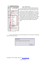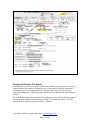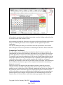
1
Cert-Pro Hoods Demo User’s manual Version 1.8x Copyright Cert-Pro Company 2006-2012. www.cert-pro.com Page 1 of 63 Table of Contents TABLE OF CONTENTS ............................................................................................................................. 2 INTRODUCTION: ....................................................................................................................................... 4 PROGRAM VERSIONS: ............................................................................................................................ 4 OFFICE VERSION. ....................................................................................................................................... 4 TECHNICIAN VERSION. ............................................................................................................................... 4 PROGRAM DESCRIPTION. ..................................................................................................................... 5 INSTALLING THE PROGRAM................................................................................................................ 6 INSTALLING THE OFFICE PROGRAM ............................................................................................................ 6 INSTALLING THE TECHNICIAN PROGRAM ................................................................................................... 7 STARTING THE PROGRAM .................................................................................................................... 8 MAIN MENU ..............................................................................................................................................10 Spell Checking. ....................................................................................................................................12 Standard Navigation interface .............................................................................................................12 Figure 3 Menu and Navigation Bar .....................................................................................................12 Searching for Data...............................................................................................................................12 Search Criteria ....................................................................................................................................13 Show or Hide Omitted Search Values ..................................................................................................16 List Views ..............................................................................................................................16 ENTERING DATA INTO THE PROGRAM. .............................................................................................18 CLIENT DATA ............................................................................................................................................18 HOOD DATA ..............................................................................................................................................18 STANDARDS...............................................................................................................................................18 WORK ORDERS ..........................................................................................................................................18 SYNCH RECORDS .......................................................................................................................................18 CLIENT MODULE .....................................................................................................................................19 ADDING NEW CLIENTS...............................................................................................................................21 IMPORTING CLIENT RECORDS....................................................................................................................22 WORK ORDER MODULE ........................................................................................................................23 STEPS FOR CREATING A NEW WORK ORDER ............................................................................................27 EDITING A WORK ORDER ...........................................................................................................................27 DELETING A TEST REPORT FROM THE WORK ORDER ...............................................................................27 PRINTING WORK ORDER TEST REPORTS ...................................................................................................28 CERTIFICATION TEST REPORTS........................................................................................................28 EDITING REPORT ACCEPTANCE VALUES ....................................................................................................29 Locking Report Specifications .............................................................................................................30 ENTERING CERTIFICATION TEST RESULTS ................................................................................................31 COMPLETING A TEST REPORT....................................................................................................................32 COMPLETING A WORK ORDER...................................................................................................................33 REVIEWING A WORK ORDER .....................................................................................................................33 AUTOMATIC DATA COLLECTION. ........................................................................................................34 COLLECTING READINGS 1 BY 1 .................................................................................................................34 LOAD STORED READINGS ..........................................................................................................................35 Copyright Cert-Pro Company 2006-2012. www.cert-pro.com Page 2 of 63 EQUIPMENT MODULE ...........................................................................................................................38 ENTERING NEW EQUIPMENT RECORDS......................................................................................................39 EQUIPMENT SPEC LOCK ............................................................................................................................40 IMPORTING EQUIPMENT RECORDS.............................................................................................................40 CONFIGURATION ....................................................................................................................................44 CONFIGURATION TOP TAB.........................................................................................................................44 Default Technician ...............................................................................................................................44 Allow 1 Hood Per WO .........................................................................................................................44 Test Inst. ...............................................................................................................................................45 BIO HOODS TAB ....................................................................................................................................45 EDIT REPORTS .......................................................................................................................................45 REPORT PRINT STYLE .........................................................................................................................45 INSTRUMENT COMMUNICATION SETUP .....................................................................................................45 DEFAULT INSTRUMENT FOR THIS TECHNICIAN .........................................................................................46 VALUE LIST SETUP ....................................................................................................................................46 DATA FILES TAB ........................................................................................................................................46 FUME HOODS TAB ................................................................................................................................47 EDIT REPORT TEXT ..........................................................................................................................47 REPORT PRINT STYLE ......................................................................................................................47 SET-UP FOR DATA SYNCHRONIZATION WITH TECHNICIAN COPIES ...................................48 Create A Network Data Folder ............................................................................................................48 Configure The Data Synch Folder .......................................................................................................49 Adding Additional Technicians ............................................................................................................50 Activating Additional Technician License Seats. .................................................................................51 Configuring Technician Numbers on Technician Software .................................................................52 APPENDIX A RUNNING HOODS ADMIN IN SHARED MODE ........................................................54 Copyright Cert-Pro Company 2006-2012. www.cert-pro.com Page 3 of 63 Introduction: The demo version of the Cert-Pro hood certification program is designed to allow prospective clients to use a full-functioning version of the program for a limited time (typically 60 days). The demo version does provide near-complete functionality of the commercial program. The following program elements are not functional in the demo program: Graphic Elements. The Cert-Pro Hoods program provides surface mapping of HEPA filter repairs. The mapping function is not available in the demo program. The leak reporting is fully functional and will track all repairs performed on filters and calculate individual patch areas and overall patch area but the graphic mapping of the filter face is not displayed. Program Versions: The Cert-Pro Hoods program is delivered in two separate program packages. The programs are briefly described below: Office Version. The Office version is required to use the program. This version is used to create all client records, equipment records (Hoods, Cleanrooms and test standards) and finally, to generate work orders and certification report templates for technicians to execute. Once records are created by the administrator, the records are sent to each field technician’s computer. Once a technician completes a certification work order, the information is then electronically transferred back to the administrator for review and report distribution. It is possible to use the Office copy of the program for generation of all records and also execution of the certification reports without the use of a technician copy of the program. This may be done for small certification companies or hood manufacturers where a dedicated office system may not be necessary. Technician Version. The technician copy of the program is required whenever it is desired to have a copy of the program dedicated to the office and have field technicians execute the work orders in the field. Each field technician will require one copy of the technician version of the program. The technician version receives all certification records from the administrator. The technician then performs the work and documents all test data and inspection results on test report and repair reports. Once all field activities have been completed, the technician then transmits all test data back to the office administrator for review and distribution. If desired, the technician may print certification reports in the field. A separate licensed copy of the technician program must be purchased for each simultaneous user (technician). Certain security features are implemented to ensure only licensed technicians send and receive data. Copyright Cert-Pro Company 2006-2012. www.cert-pro.com Page 4 of 63 Program Description. The Cert-Pro Hoods program is a custom designed relational database application for Windows based computers. The program is designed on a FileMaker Pro database engine which provides the database structure and some program functionality. Significant additional custom programming has been added to the application to provide fully automated test and certification of many types of hoods, Isolators, Isolation rooms and small Cleanrooms. The Cert-Pro Hoods program is designed as a client/server application. This allows for fully electronic data transfer between the administrator located at an office and an unlimited number of technicians in the field. The program provides customized report generation to ensure a consistent and compliant report is generated that is accurate, complete regardless of the type of testing performed or what type of equipment is being certified. Additionally, much time and effort have been applied to automating as much of the certification process as possible. Some of the automation features of the program include: Automatic generation of equipment specifications. Automatic report generation based on individual equipment and client requirements. Electronic or manual data entry for field test results. The system will electronically collect data from your anemometers, particle counters and micromanometers. This eliminates the need to ever type test data into the computer. Fully automatic calculations for all certification intermediate and final results. The technician does not perform any manual calculations during the entire certification process. Assurance all test data is recorded. The test report cannot be completed with a PASS rating if the technician has not recorded all required readings. Transmittal of work orders, test reports and test results over an intranet, internet or local media connection. This allows for full report generation, completion and reporting with no need for technicians to visit the office. Complete electronic history of all testing and repairs ever performed using the system. This includes: o Full historical records are available to all field technicians, while they are in front of the equipment. o Full historical records are available to the office administrator for quick retrieval of data while the client is on the phone. Ability to customize much of the report text to allow customized test reports. Multiple reports including summaries, cover letters, text reports, raw data reports, certification certificates and future certification letters. Copyright Cert-Pro Company 2006-2012. www.cert-pro.com Page 5 of 63 Installing the Program. The Cert-Pro Hoods program is distributed as two separate programs, the Office version and the Technician version. Each of these programs are distributed as a single installer program file (One technician and one Office). You will typically receive these installer files as a download link in an email. Download the files to your computer and save each file to an easily accessible location such as a USB flash drive or your desktop. Installer Program Links typically expire in 30 days so make sure you download your installer files promptly. Save a copy of the downloaded files for archival purposes. Installing the Office Program The Office version of the program will be installed on a Single administrator’s computer. There must only be one installed version of the Office program. This program can be used by a single administrator or by multiple administrators. Some considerations as to how and where this program is installed are outlined below: Method A – Single User. The simplest installation method is to install the Office program on the primary administrator’s computer. This will allow the fastest access to the database but will not allow other computers to access the program. If others need to access the program, they will need to use this administrator’s computer to do so. When initially setting up the program (creating client and equipment records, etc.) this is the recommended installation method. The program can be later moved to one of the methods described below by simply copying the Hoods folder to the new location. Method B – Network Single User. The Office program may be installed on a network disk drive. This will allow multiple staff members to access the program. Note that in this mode, there may only be one person using the program at a time. If someone else needs to access the program, the current user will need to exit the program first. To use the Office copy of the program in this manner, install the program in a network folder location where all users have full rights (read, write, edit). Then copy the shortcut to the Hoodsxxx.Exe file for each user’s computer. NOTE – This method will result in slower performance due to network communications. If your network speed will not adequately support this method, copy the Hoods folder to a local drive and use as Method A. Method C – Network Simultaneous User. In order to use the program as a multi-user application, each user must have a licensed copy of FileMaker Pro installed on their computer. Installing the program in this manner allows for up to 5 simultaneous users to access the program. In this mode, the program ensures record locking and other multi user features. To use the program in this manner, install the program on a network folder where all users will have full access rights (read, write, edit). See Appendix A of this manual for a complete description on how to use this program in multi-user mode. Copyright Cert-Pro Company 2006-2012. www.cert-pro.com Page 6 of 63 NOTE – This method will result in slower performance due to network communications. If your network speed will not adequately support this method, copy the Hoods folder to a local drive and use as Method A. Program Installation Steps Download or copy the installer program to the computer you want to install the program on. Because the installer is a single file, the program can be easily copied to a flash drive for transfer to the desired computer. Start installer program by double clicking on the installer file icon. Read and agree to the license agreement. Provide the computer location you wish to install the program to (see method A-C above). Typically, you will create a new folder in the root directory of your C: drive. o Do not install to the root directory or your desktop without providing a folder name. If you do, all program files will be installed directly to this location rather than a folder. Allow the program to install. After installation is complete, the installer will place a program shortcut on your desktop. Double click on this icon to start the program. Installing the Technician Program The Technician version of the program will be installed on each technician’s local computer. This is typically a laptop the technician will take into the field with them. If you purchased multiple technician licenses, you will use the same technician installer program to install the technician program on each technician computer. In this case it is easiest if you save the technician program installer to a USB flash drive and copy the technician installer program to each technician computer from the flash drive. You may also download the installer file to each technician computer directly from the email link if a flash drive is not available. Note – The standard program includes 1 technician license. You must purchase a technician license for each additional technician who will be using the program. Contact Cert-Pro for pricing of additional technician licenses. You can verify how many licenses are enabled by viewing the About screen on the Office version of the program. Program Installation Steps Download or copy the installer program to the computer you want to install the program on. Because the installer is a single file, the program can be easily copied to a flash drive for transfer to the desired computer. Start Technician installer program by double clicking on the installer file icon. Read and agree to the license agreement. Provide the computer location you wish to install the program This should always be a local disk drive, not a network drive. Typically, you will create a new folder in the root directory of your C: drive. Copyright Cert-Pro Company 2006-2012. www.cert-pro.com Page 7 of 63 o Do not install to the root directory or your desktop without providing a folder name. If you do, all program files will be installed directly to this location rather than a folder. Allow the program to install. After installation is complete, the installer will place a program shortcut on your desktop. Double click on this icon to start the program. Starting the Program Each time you start the program, you will be prompted for a login ID and password. The login for the program versions are listed below: Admin Version – User Name Office Password: 4321 Technician version User Name: Technician Password: 1234 After logging in, you will be presented the main menu for the program. The administrator main screen is different from the technician screen as shown in Figure 1below. Copyright Cert-Pro Company 2006-2012. www.cert-pro.com Page 8 of 63 The Cert-Pro Hoods program uses multiple databases (modules) to store and access relevant information. The following modules are used to store information in the program: Clients – Stores all relevant client info (Name, Address, contact info, etc.) Work Orders – Stores all individual work orders. A work order is used to compile all test reports for a specific job. A work order may contain an unlimited number of test reports and repair reports related to a job. Hoods – Stores all information for all client hoods, Cleanrooms, Isolators, etc. The hood database stores all equipment information including make, model, serial number, location, next due date and status of a hood or room. Additionally, all relevant test specifications are stored in the hoods database. Standards – Stores all information on test equipment used to perform certification testing (anemometers, photometers, particle counters, etc.). Configuration – Allows user to configure the program for specific applications. Synch Data – o Admin Copy - Sends all new records, test reports and test data to the technician. The program will then receive all test data that the technician has previously synched. o Tech Copy – Sends all completed test reports and work orders to the server. The program will then receive all new records sent from the admin copy. About – Clicking on this icon will display registration and version information for the program. Exit – Clicking the Exit button will exit the program and close all database modules. Each program module can be accessed by clicking on the module button from the main menu screen shown in Figure 1. Copyright Cert-Pro Company 2006-2012. www.cert-pro.com Page 9 of 63 Main Menu Each time you run the Cert-Pro Hoods program, the main menu will be displayed. The main menu contains icons which provide access to each of the programs modules. The menu displayed will be different depending on if you are running the technician or administrator version of the program. See figure 1 for a copy of the admin main menu and figure 2 for a copy of the technician main menu. As you will note, the technician version of the program does not contain links to the client or standards modules. Functions related to entry and editing of client records and test standards (instruments used for certification) are limited to administrator access. Figure 1 Admin Version Main Screen Copyright Cert-Pro Company 2006-2012. www.cert-pro.com Page 10 of 63 Figure 2 - Technician Main Menu Directly below each icon on the main menu is a small pull down option menu. This option menu allows you to select the action that is taken each time you click on one of the menu icons. Note that the action for each of the main menu icons can be set independently. The available choices for this pull down option menu are described below: New – If you set the icon option to New, each time you click on the menu icon, a new record for that module will be created. This is useful if you are creating new records each time you enter the module. View Last – when set to View Last, the last record viewed will be displayed when you enter the module. List - when set to List, a list view will be displayed showing all records in the module. The list view allows for subsequent searching and sorting of the set of records. Search - when you set the icon option to Search, the record detail screen will be displayed and the program will enter the search mode. When in search mode, you may fill out one or more fields with the data you are looking for and then press the ENTER key to initiate a search. In addition to the module icons described above, the following buttons are available from the main menu: Synch Data – o Admin Copy - Sends all new records, test reports and test data to the technician. The program will then receive all test data that the technician has previously synched. Copyright Cert-Pro Company 2006-2012. www.cert-pro.com Page 11 of 63 o Tech Copy – Sends all completed test reports and work orders to the server. The program will then receive all new records sent from the admin copy. About – Clicking on this icon will display a screen showing registration and version information for the program. Exit – Clicking the Exit button will exit the program and close all database modules. Spell Checking. Most text entry fields include a spell check feature. When words are entered that are not currently in the dictionaries, the word will be underscored with a red squiggly line. Right click on any word with the red squiggly line and then select Suggested spelling to view suggested corrections. If the word is not recognized, but correctly spelled, you can select the Add to add it to the dictionary. Standard Navigation interface. All program screens include standard navigation interface items. These items will appear as icons on the top toolbar of each screen, where appropriate. Figure 2 below shows a typical navigation bar. Figure 3 Menu and Navigation Bar The actual menu icons displayed will vary depending on the screen you are viewing. Most toolbar elements will display a tool tip if you stop your mouse pointer over the item. Record Navigation, searching and showing all records is accomplished by clicking on the appropriate record navigation buttons on the right side of the screen. The Back Icon The program makes extensive use of the Back Button. Each time you click the Back Button, you will be taken to the previously displayed screen. Searching for Data Most screens in the Hoods program allow for the user to search for records containing specific information. Searches may be performed from the detail screens (work order, client, equipment screens, etc.) or from a list view. While list views will be easier to use for searches, list Copyright Cert-Pro Company 2006-2012. www.cert-pro.com Page 12 of 63 views typically display a limited number of all fields available. If the list view does not contain all the fields you wish to use in your search, you will perform a search from the detail screen. For example, a user may want to search for all work orders where a specific anemometer was used in a specific date range. This type of search cannot be performed from the Work Order list view because the test instruments used for certification are not shown on the work Order list view screen. Therefore the search will be performed from the Work Order detail screen, by following the steps below: Go to the work order detail screen. (Click on the work order icon from the main menu.) Click the Search icon from the Work Order detail screen toolbar. The screen will clear all currently displayed work order information and pause for the user to fill in the information to be used for the search. Enter all search criteria into the desired fields (Anemometer Equipment Number and work order date range). You may enter search criteria into any or all of the fields as necessary to find the specific work orders you need. See the section titled Search Criteria below for an explanation of how to enter ranges and other search limiters. Press the ENTER key to complete the search. All work orders meeting the supplied search criteria will be compiled into a Found Set. A Found Set, in this example is a subset of work orders that meet the criteria for the search just performed. Once a Found Set has been defined, by performing a search, you may navigate and print reports based only on the found set, or limited number of records, as needed. You can clear a Found Set by clicking on the Show All button in the navigation toolbar or perform a new search which will clear the current found set and replace it with records matching the latest search. After a search is performed, the first record in the Found Set will be displayed. The user may then navigate through the found set, by clicking on the record navigation buttons (Next record, Previous Record, etc.), or go to a list view which will show only the records in the current found set. See the List View description below to perform a search in List View. Search Criteria When entering search information, you will need to enter certain symbols to allow entry of ranges or greater than or less than qualifiers for the search. The symbols used to allow this type of search are listed below: Entering This Symbol = == Will Result In… Example Show all records where this field is blank Field Content Exact Match. The entire field must exactly match the search criteria entered. Otherwise, entering = (with no other data) = = Joe would show only records where ‘Joe’ was entered. Joe A, Joe Tech, etc. would not meet these Copyright Cert-Pro Company 2006-2012. www.cert-pro.com Page 13 of 63 > ‘Joe’ into a field would show all records where Joe was found anywhere within the field (Joe A, Joe Tech, Joe, etc.). All records where data is greater than what was entered for search criteria < All records where data is less than what was entered for search criteria … All records within the specified range 2008, 08/2008 Entering a year in a date field will result in all records with that year in the date field being shown. In addition, if you want to search for all records in a month of a year, enter 08/2008. search criteria. Note this symbol can be used on number, date or text fields. > 100 Will show all records where this field is greater than 100. Note this symbol can be used on number, date or text fields. < 100 Will show all records where this field is greater than 100. Note this symbol can be used on number, date or text fields. 01/01/2007…12/31/2007 will show all records between the dates specified. Note this symbol can be used on number, date or text fields. 2008 will show all records in 2008. 08/2008 will show all records in August, 2008. Copyright Cert-Pro Company 2006-2012. www.cert-pro.com Page 14 of 63 Search Symbols Hint When you are in Search mode, the program will display a menu bar on the left side of the screen. This area will show the current search status as well as allow you to enter the symbols above. To use the search symbols, click into the field you want to enter search criteria, click on the Symbols arrow to display a pull down list of all available search symbols. (See Figure to right). You may then click on the desired search symbol to enter into the field you are searching on. Enter the search criteria into the field. Once you have filled in all needed search criteria, click on the Continue button or press ENTER to perform the search. If your search results in no records being found, an error message box will display and all records will be shown. Copyright Cert-Pro Company 2006-2012. www.cert-pro.com Page 15 of 63 Show or Hide Omitted Search Values After you have completed a search, the program will show all records that match the search criteria you entered. The set of records that are shown after a search is performed is called a Found Set. There will be times when you would want to see only the records that did not match the search criteria rather than did match the search criteria. This is referred to as showing all Omitted Records. The Show Omitted icon found on the top menu bar, allows you to switch the found set from all records matching the search criteria to all records that did not match the search criteria. For instance, if you wanted to show all records, except those done by a certain technician, you would perform a find for all records done by the technician. After performing the search, click the Show Omitted icon to show all records except those performed by the technician. List Views List views are available in most of the data screens including client, work order, equipment and standards. After clicking on the Show List View icon, the list view will display the current found set in a table format. All list view screens contain the same user elements as shown in figure 3 below. The list view can show all records in the database, or a subset of records. To limit the records shown in a list view, the user will apply certain filters, or limits, for each of the fields. Filters may be set for any combination of the yellow filter fields at the top row of the list. Once all desired filter criteria has been entered, click on the Apply Filter icon. The program will then search the database and displays all records that meet the current filter criteria. The list view may also be sorted by clicking the column header that you wish to sort the list by. More complex multiple column sorting can be applied by clicking on the sort icon and selecting the fields to sort. Copyright Cert-Pro Company 2006-2012. www.cert-pro.com Page 16 of 63 Figure 4 List View (Work Order Screen) Copyright Cert-Pro Company 2006-2012. www.cert-pro.com Page 17 of 63 Entering data into the program. While the demo programs include several test records to allow you to use the program with as little effort as possible, users will eventually want to enter some test data of their own. The demo copy of the program allows users to enter an unlimited number of records into the client, equipment, standards and work order databases. All new records are entered into the Admin copy of the program. When all data entry is complete, synch the admin program with all field technician copies by clicking on the Synch Data button on the Main Menu. After the Admin copy of the program is synched, each technician can then synch the technician copy of the program to receive all newly created work orders and hood records. The proper order to enter new records is shown below: Client Data. Prior to entering hoods, work orders or test reports, a client record must be created. This allows you to enter hood records that are linked to the client. One client record will be created for each client that you wish to perform certification work for. To enter the client module, click on the Client icon from the main menu. Click on the New Record icon to enter a new client record. Return to the main menu when complete. Hood Data. After the client record is entered, hood records may be entered for any existing client record. Click on the Equipment Icon from the main menu. Click on the add or duplicate buttons to add a new hood record. Fill in all hood information (see Equipment Module for more information). Return to the main menu. Standards. Test standards are the equipment records for the individual test equipment that is used for certifications. For example, an air velocity meter or a particle counter would be a test standard. You will create a new test standard record for each piece of test equipment that you own. Click on the Standards icon from the main menu to access the test standards module. Once in the test standards module, you may click on the Add or Duplicate icon to add new test standards records. Return to the Main Menu when complete. Work Orders. Once you have entered one or more client records, have entered the hoods associated with the client and entered any test instruments (Standards) which will be used to perform the certification, you may enter work orders to do the actual testing. Click on the Work Order icon from the main menu. Follow instructions in the Work Order section of this manual for detailed instructions on entering new work orders. Synch Records. Click the synch Data icon from the main menu. This will synchronize all the data entered in the above steps to each registered field technician copy of the program. The technician may now collect all certification data and synch the test data back to the administrator after completion of the work order(s). Copyright Cert-Pro Company 2006-2012. www.cert-pro.com Page 18 of 63 Client Module All information for your client base is stored in the Client module. Once you create a client record, you may then create equipment records and work orders related to this client. The client screen will display all client contact information as well as direct links to a full history of work orders and equipment records related to the currently displayed client. Click on the Clients button from the main screen to access the Client module. The Admin version of the program provides complete client information as shown in Figure 3 below. Use this screen to add or edit client information as needed. The right side of the client screen displays a portal showing all equipment that has been assigned to this client. Clicking on the Work Orders tab in the portal will change this view to all work orders that have been assigned to this client. Clicking on a portal entry line will display the selected hood or work order record. Click the Add Record button to add additional clients. Existing client information may be edited by clicking on the edit button . Clicking on the Info button will display the field information for this client (see figure 3). This field information is the client information that is available to the technician for field use. This field is intended to be used for general instructions related to this client such as directions on how to get to the client, instructions on how to contact the client or other general information related to this client that would be helpful for the technician to see. Copyright Cert-Pro Company 2006-2012. www.cert-pro.com Page 19 of 63 Figure 5 Client Screen – Admin Version The Admin version of the program provides complete client information as shown in Figure 4 above. Use this screen to add or edit client information. The right side of the screen displays a portal showing all equipment that has been assigned to this client. Clicking on the green Work Orders button in the portal will change this view to all work orders that have been assigned to this client. Clicking on a portal entry line will link you to the desired hood or work order record. Click the Add Record button to add additional clients. Clicking the Info button will display the field information for this client (see figure 4). When using the Technician version of the program, the client information screen is the only screen available to the technician. This is to prevent unauthorized viewing and searching of client information. The comment area below the client information allows adequate space to provide specific directions, access notes and other client information that will be useful to the field technician. Copyright Cert-Pro Company 2006-2012. www.cert-pro.com Page 20 of 63 Figure 6. Client Info Screen Adding new Clients Clients may be added to the database by clicking on the Add Record button. When a new record is added, the screen will clear all current information and display a blank client record. Fill in each fields as described below: Synchronized: This field will automatically populate as No. A No setting in the synchronized field will cause this new client record to be sent to all field technicians. You may manually set the synchronized field to control when client information is updated on the technician field computers by setting this field to Yes or No. A No setting will send all client information to the technicians. A yes setting will ignore sending this information during the next synch. This field is automatically set to No any time a new record is added or an existing record is edited. Client ID: This field is automatically populated with the next client ID. You may accept the suggested client ID, or supply your own client ID. Note the Client ID must be a unique identifier that has not previously been used. If you enter a client ID that has been Copyright Cert-Pro Company 2006-2012. www.cert-pro.com Page 21 of 63 used before, you will receive a message box instructing you to change the client ID to a unique value. The Client ID may be any alpha numeric identifier. Company Name: Enter the name of the company, as you would like it to appear on all correspondence. Company Alias Name: Enter the name of the company, department or other information that will help to identify this current record. For example, you may have a company that has several departments or divisions which use different PO numbers or mailing addresses. The alias name can be used to identify these different departments but still allow the use of the official company name. For example, if you had a client with three separate building, you could set up 3 separate client records for this one account. The company name for all 3 accounts would be the same, but each alias name would be unique (XYZ Company Bldg. 20, XYZ Company Bldg. 22, XYZ Company Bldg. 30). This would then allow you to better track equipment to a specific building but mail the reports to the main company name. If you do not provide an alias name, the alias name will be set to match the company name when you exit the record. Client Certifications Expire: Use this field to specify when a client certification will expire. Some clients want their certifications to expire on the same day as when the last certification was performed, others may want their certification to expire the last day of the month in which it was certified. This field is used to determine the next certification date on all reports and the future certification database reports. Address, city, state, zip: Enter the company address, city state and zip code in these fields. Phone #: Enter the main company phone number here. Fax #: Enter the company fax number here. Industry: Enter the industry classification for this client here. This allows you to identify the specific industry the client is in, for example, semiconductor, pharmacy, hospital, etc. This field may be left blank if desired. GEOCode Data: The GEOCode data allows for automatic entry of the client latitude and longitude as well as distance from the office. This information is automatically collected from Google when you click on the GEOCode Data link. Note the distance is “as the crow flies” so compensation may be necessary to determine the exact travel distance. This information is intended to assist in scheduling service calls. Contacts: Up to three separate contacts may be entered for each client. Price Guidance: Enter price guidance information into this field. The price guidance information is intended to provide pricing info related to this client. This information is available from the Client screen, the hood records screen and from the future cert report page. Importing Client Records. If you have a current database or spreadsheet with client information, this information can be imported into the Cert-Pro Hoods program by use of an Excel spreadsheet template. Once all client information is compiled into the Excel spreadsheet template, click on the Import XLS button to import in all client information. Contact Cert-Pro for a copy of the Excel import template. Copyright Cert-Pro Company 2006-2012. www.cert-pro.com Page 22 of 63 Work Order Module Prior to creating work orders, the client information and all hood information must be entered into the program. All field certification work is compiled into work orders. Each work order will contain the client information, certification requirements, certification test results, any repairs performed and a record of the test standards that were used during the certification. A work order may contain test data for one or more individual hoods. For example, if a client hospital is due for certification, you may create a single work order with the pharmacy hoods, lab hoods and surgery suites all under one work order. Alternatively, you may create individual work orders for each department, or even a separate work order for each hood or surgery suite. The work order module is accessed by clicking on the work order icon from the main menu. Once in the work order module, the screen will display the last viewed work order as shown in figure 6 below. The example work order shown in figure 6 includes test reports for 3 fume hoods and one unidirectional hood. Each individual test report is shown in the test report portal on the right side of the work order detail screen. Additionally, there is one repair report associated with this work order shown in the repair report portal at the bottom right side of the work order detail screen. Figure 7 Work Order Screen Copyright Cert-Pro Company 2006-2012. www.cert-pro.com Page 23 of 63 The work order shown in figure 7 is an example of a single work order used to perform test and certification of four separate hoods, 2 Bio Hoods and 1 Fume Hood. The work order also has 2 Inspections reports and one work order comment report associated with it. Each individual test report for this work order is displayed in the Test Report Portal at the right side of the screen. All test results collected during the certification are entered into the individual test reports. To access a test report, click on the description of the test report you want to view. For the work order sample shown in figure 7, the technician would go to the first hood to be certified, click on the test report for the hood and enter all test data as it is collected. As the technician goes to the next hood to test, return to the work order screen and select the next test report to complete. This process will be followed until all hoods have been tested. The work order also contains the information for what test standards (instruments) were used during the certification tests. The technician will enter each standard in the Standards used section at the bottom of the work order. Clicking on the Equipment Number (EN) field will display a pull down menu with all standards of the selected type listed. For example, if the technician clicks on the Anemometer standard EN, a list of all entered anemometers will display in a pull down menu for selection. Once a standard is selected, all pertinent information (description, model and Cal due date) will be displayed automatically. Optionally, the technician can click the test standards default button to load all the default test standards for this technician automatically. Each test report will pass thru several statuses as the test report progresses from creation to closure. For example, when a new test report is created, it will automatically be in Incomplete status. As a technician starts performing testing, a report will immediately show a Failed Status if any individual test fails to meet the certification requirements. After a technician completes all required testing, and all tests pass, the report will automatically go to Pass status To provide a simple method for determining the status of a work order, the status of each report is displayed at the right side of the test report portal. There are 3 different icons that may be displayed to indicate report status: Incomplete Status. This icon indicates that all testing is not complete. All testing performed so far has not failed certification requirements. Pass status. This icon indicates the certification testing is complete and all results passed. Failed Status. This icon indicates that one or more test results failed the certification requirements. Copyright Cert-Pro Company 2006-2012. www.cert-pro.com Page 24 of 63 In addition to the test status icons shown above, as the technician completes each test report, the completed checkmark will display adjacent to the status icon. This checkmark indicate the technician has completed the test report and updated the next certification due date for this equipment. If during the certification process, the technician changed any of the test report acceptance criteria or equipment information, the test report will be highlighted yellow. This yellow highlight is an indication to the administrator to review the test report for changes to the specifications. See the following chapter for more detailed information on field changes to test criteria. Copyright Cert-Pro Company 2006-2012. www.cert-pro.com Page 25 of 63 Creating a New work Order To create a new work order, click on the New Work Order toolbar icon . This will display a new screen requesting the new work order number to create. The work order number will be populated by the next available work order number by default. You may use this number by clicking the ENTER key, or enter a new work order number in the work order number box and pressing ENTER. Once you enter the new work order number, the system will search the work order database to ensure the work order number does not already exist. If the work order already exists, a dialog box indicating this will appear. You will then have the option to view the existing work order, cancel the creation of a new work order or try again. If the work order number does not exist, the new work order screen will be displayed (see figure 7). Figure 8 New Work Order Screen Copyright Cert-Pro Company 2006-2012. www.cert-pro.com Page 26 of 63 Steps for Creating a New Work Order: From the Work Order screen, Click New Work Order button. Enter the new work order number. Select the client name from the pull down list. Select the work type (PM or CM) Select the scheduled date. Set the work order status, the field will be set to In Progress by default. Select work type (Certification, Repair or Repair and Cert) Select the technician to assign this work to. Select the client equipment to certify from the equipment portal on right side of screen. You may select one or more items to include in the work order test reports. To select an equipment to certify, click on the gray add button adjacent to the equipment description. When you click the gray button, the equipment will be highlighted yellow and the equipment number will be added to the equipment selection list on the work order screen. Clicking the selection button for already selected equipment will de-select that item. You may select as many items to certify as needed. If all listed client equipment is to be selected, you may click the Select All button below the equipment portal list. Type in work scope, or click the Pm Scope button to fill in automatically. Click the Create Reports button to create test reports for all selected pieces of equipment and return to the work order screen. You may now review any of the created test reports or return to the main menu to synch the database. Synching the database will transmit all newly created work orders and test reports to each of the registered technicians for execution. Editing a work Order If after creating a work order, you find you need to change information, add additional hoods, etc., you may edit the work order by clicking on the edit button in the toolbar. This will return you to the new work order screen shown in figure 6. At this point, you may update any information related to the work order. Deleting a Test Report from the Work Order To delete an existing test report from a work order, navigate to the report summary screen by clicking on the report description in the report portal. Select the Delete button from the report summary screen toolbar. Once you click on the Delete icon, the report will be marked for deletion. The next time the program is synched, all test reports marked for deletion will be removed from the office copy of the program and all field service copies. Prior to merging data, the deletion flag can be removed from any report marked for deletion by clicking on the delete icon. Caution when a test report is deleted, all test data collected for this test report is also permanently deleted. Copyright Cert-Pro Company 2006-2012. www.cert-pro.com Page 27 of 63 Printing Work Order Test Reports Clicking the Print button from the work order screen will print all test reports and repair reports associated with the currently displayed work order. To print individual reports, click the print report button from the certification test report summary screen. Certification Test Reports Certification test results are stored and printed for each individual test report. A work order may contain 1 or more test reports. To access an individual test report, click on the desired test report listing in the test report portal on the work order screen. Once you click on a test report in the work order report portal, the test report summary screen will be displayed. (See figure 8 below). The summary screen displays the current progress for this test report and provides various links for the test report selected. Figure 9 Access test reports and repair reports Copyright Cert-Pro Company 2006-2012. www.cert-pro.com Page 28 of 63 Figure 10 Cert Report Summary Screen The certification summary screen displays all tests that are required for the certification. Additionally, as tests are completed, the results are shown in each test section along with the pass or fail status of each report. To enter the air velocity results for downflow on a bio hood, click on the Downflow Air Velocity label directly above the downflow velocity results. This will take you to the air velocity entry screen shown in Figure 12. Editing Report Acceptance values All test requirements were pre populated on the test report when the report was generated in the work order screen. The test requirement values are pulled from the individual equipment record. If the technician finds that certain test requirements are not populated, or are the wrong value, you can edit the test report values by clicking the edit button from the report summary screen. This will allow a technician to field modify the values for this report but will not change the actual equipment record values. Equipment record values must be edited from the equipment module. Only administrators can make modifications to the equipment records. Once certification report test criteria is modified in the edit screen, the test report requirements will update automatically when you return to the test report summary screen. If a technician changes any test report criteria, the field that was changed will be highlighted in yellow. Additionally, as you hover your mouse over the field, the original value will be displayed in a tooltip box. Any test report that has been modified will be highlighted in yellow flagging the report for further review by the administrator. The administrator will then view the test report edit screen for any highlighted fields. If after Copyright Cert-Pro Company 2006-2012. www.cert-pro.com Page 29 of 63 review, it is determined that the changes were appropriate, the administrator can click on the Accept Changes button to update the equipment record to match all values on the current test report. Once this update has occurred, the yellow highlights will be removed from each modified filed and the highlight bar will be removed from the test report on the work order screen. Additionally, if it is determined the spec changes were not correct, clicking on the Refresh button will restore the equipment record specifications to the test report and remove all highlighting. Locking Report Specifications After a final review of equipment test specifications has been performed, it may be desirable to prevent future changes to report specifications by the technician. Each equipment entry screen includes a Specs Locked Icon. When the equipment specs are locked, the technician will no longer be allowed to modify any of the test report specifications. The specs lock applies at the equipment record level so each equipment record may be individually set to locked or unlocked as appropriate. See the Equipment Entry section of this manual to read more about specification locks. Copyright Cert-Pro Company 2006-2012. www.cert-pro.com Page 30 of 63 Figure 11. Editing Report Criteria – BSC hood Entering Certification Test Results Certification test results (air velocity readings, air volumes, particle counts, etc.) may be entered in either the Admin or Technician copy of the program. Both the Admin and Technician copy of the program allows for electronic data collection, directly from supported instruments, or manual typing of certification test data into the data collection screens. To enter the data collection screens for the certification report, click on the description of the test from the summary report screen (see figure 9 for summary screen). This will display the data collection screen (see figure 11 below). Copyright Cert-Pro Company 2006-2012. www.cert-pro.com Page 31 of 63 Figure 12 Air Velocity Data Collection Screen (Technician Copy) All test data is entered into the individual test results screen by clicking on the title of the test results section of the summary screen. After entering the results for all test areas, the green check mark will appear on the report status icon indicating all tests have been completed and the equipment passed the certification. If at any time during the testing, a result fails to meet the requirements, the red check mark will appear on the test report status icon indicating the hood has failed certification. Completing a Test Report. Each test report must be completed by the technician after all testing is complete. By completing the test report, the technician is indicating all test are complete and will then have the opportunity to set the next certification date for the equipment being certified. To complete a test report, the technician will click on the Change Status button at the top of the report summary screen. If all tests have been completed, and the hood has passed certification, the test report will be marked complete and a dialog box will appear prompting the technician to enter the next due date for the certification. After entering the next certification due date, the report will be completed and marked for transmitting during the next synch. If the test report is not completed but the technician wishes to mark the test report complete, the tech will click on the Change Status button at the top of the test report summary screen. A dialog box will be displayed warning that not all tests are complete. If the technician chooses to mark the report as complete, the hood next certification date will be left with the current next certification date. Additionally, any test reports that are printed without all tests complete will be marked as for information only and will not contain a Pass or Fail result in the certification summary paragraph of the test report. Copyright Cert-Pro Company 2006-2012. www.cert-pro.com Page 32 of 63 If the test report is currently failing and the technician wishes to mark the test report as complete, the tech will click on the Change Status button at the top of the report summary screen. A dialog box will be displayed warning the technician that the equipment has failed certification. If the technician chooses to complete the report, the equipment will be marked as tagged out in the equipment database pending future repair. Additionally, any test reports that are printed will be marked as failed in the certification summary paragraph of the test report. The next certification due date will not be advanced on a failed certification test. Completing a Work Order. After the technician has completed all test report, the test instruments (standards) used during the certification should be populated on the work order screen. The technician will then click on the Change status button at the top of the work order screen. The program will verify all test reports have been completed and then mark the work order as complete and mark the work order for transmittal back to the administrator during the next synch. Reviewing a Work Order. Work Orders should be reviewed by the administrator after receiving any completed work orders. Prior to reviewing the work order, the administrator will typically review all test reports for accuracy and completeness. The administrator should then look to see if any of the test reports are highlighted in yellow on the work order screen. Yellow highlighted test reports indicate the technician has changed the test criteria or acceptance value on the test report. The administrator should then view the test report by clicking on the highlighted test report link on the work order screen. The program will then display the test report summary screen. The administrator would then click on the Edit button at the top of the summary screen. The edit test report screen will then be displayed. All fields that have been modified by the technician will be highlighted in yellow. The administrator can hover the mouse over any field to view the current equipment value to ensure the changes are appropriate. If the administrator wishes to accept all changes, they will then click on the Accept Changes button at the top of the screen. This will update the equipment database to match the current values of the test report. This will ensure that all future test reports are created with the updated acceptance criteria. Note this will not change any test criteria for reports that have been previously completed. If the changes by the technician are not appropriate, the administrator may click on the refresh button at the top of the report summary screen. This will revert all report test criteria back to the original values in the equipment record. Note this may cause a failure of the test report depending on what changes were made. This will not change any test criteria for reports that have been previously completed. Once all reports have been reviewed, the administrator should then mark the work order as reviewed. This is an important step as when the work order status is change to reviewed, then all test data will be transmitted to all technician copies. This allows all technician to have a full test history for the hoods covered under the work order. If work orders are not changed to reviewed status, the test data will only reside on the administrator and technician who actually performed the test. Copyright Cert-Pro Company 2006-2012. www.cert-pro.com Page 33 of 63 Automatic Data Collection. The program allows the collection of data directly from supported air velocity meters, shortridge micromanometers and airborne particle counters. There are two options for collecting data directly from TSI air velocity meters. If you have an air velocity meter that stores readings in its memory, all velocity readings may be stored in the instrument and later transmitted to the Cert-Pro hoods program. If your TSI air velocity meter does not have the ability to store readings, air velocity readings can be collected directly from the air velocity meter, as they are taken. To connect an air velocity meter to the computer for automatic data collection, refer to appendix A. Once the air velocity meter is properly connected to the computer, follow the steps below to automatically insert air velocity readings into your certification reports. Figure 13 Anemometer Controls Collecting Readings 1 by 1. Copyright Cert-Pro Company 2006-2012. www.cert-pro.com Page 34 of 63 Use this option if your air velocity meter does not support storage of air velocity readings. 1) Enter the air velocity screen (downflow, inflow or exhaust). 2) Verify meter is connected to the serial port of the computer. 3) Click on the air velocity test results cell where you want to store the first air velocity reading. 4) Click on the 1 by 1 readings icon (see Figure 12) 5) Follow the on screen instructions for key presses on the TSI. 6) All readings will be automatically inserted into the air velocity results grid. When all readings are complete, click on the Stop Collect From Anemometer button. 7) As air velocity readings are collected, the air velocity readings will be inserted and the cursor will automatically pass to the next test grid. When all velocity readings have been taken on the current row, the cursor will automatically pass the next row. If the # of Readings value is 1 (see figure 12), each reading will be collected, inserted into the report, and the cursor will advance to the next cell. 8) If you wish to take more than 1 reading for each velocity location, change the value of the # of Readings to the desired number of readings to take at each location. When collecting data, the configured number of velocity readings will be taken at the current cell. When complete, the average for the current location will be entered into the cell and the cursor will pass to the next cell and wait for additional readings. Load Stored Readings. If your TSI anemometer is capable of storing air velocity readings, the Cert-Pro Hoods program can collect all stored readings from the anemometer and place them into the air velocity data collection screens. The user can then instruct the program where to load the readings, including where to start loading and how many readings to insert into the test record. To perform a reading dump and load the desired readings into the report, follow the instructions below: 1) Collect all necessary air velocity readings, storing each reading in the TSI anemometer. 2) Connect the meter to the COM port of the computer. 3) Click on the Load Anemometer Stored Readings button. 4) Follow on screen prompts. 5) After the readings are collected, click on the View Collected Data button (Figure 10). 6) When you enter the collected data screen, the program will label each stored reading with a sample # in Red (see Figure 11). 7) Review the collected data and determine what sample you want to start at for loading the velocity readings into the report. 8) Enter the starting sample into the Parse start field on the screen. 9) Return to the air velocity data collection screen. 10) Place the cursor in the cell you wish to start inserting the test data. 11) Click on the Load Readings Into Report button. Copyright Cert-Pro Company 2006-2012. www.cert-pro.com Page 35 of 63 12) All velocity readings will be loaded into the report, starting on the reading that you specified as the Parse Start and ending when all readings have been loaded, or the number of required readings has been met. Note: The Parse Start function outlined in the steps above allows for multiple air velocity records to be collected and dumped into the program at one time. For example, on a BSC, downflow air velocities and exhaust filter velocities may be collected and stored in the meter. After collecting all air velocity readings, load them into the Hood program. Start the parse at reading #1 for the downflow (33 Readings). Next set the Parse Start for velocity reading 34. Enter the exhaust filter screen and load the remaining velocity readings into the exhaust filter velocity screen. The only limitation on the number of readings allowed is the limit of the air velocity meter (typically 500 reads). Copyright Cert-Pro Company 2006-2012. www.cert-pro.com Page 36 of 63 Figure 14 Multiple Air Velocity Readings Copyright Cert-Pro Company 2006-2012. www.cert-pro.com Page 37 of 63 Equipment Module To enter the equipment icon from the module, click on the Equipment button on the main menu. Depending on the configuration of your equipment button, the display will either display a detail view of the last equipment record viewed, or a list view of all equipment records. A detail view of a Zoned Downflow Biohood equipment record is shown in figure 15. The equipment module contains all the individual equipment records that have been entered into the system. Each hood or Cleanroom has an individual record which contains all required information for the test and certification. There is a menu bar the top of each equipment screen. The function for each menu icon is identical regardless of the equipment type displayed. The appearance of the equipment screen will vary depending on the type of equipment you are viewing. Figure 15 Equipment Record (BSC) Copyright Cert-Pro Company 2006-2012. www.cert-pro.com Page 38 of 63 Entering New Equipment Records Click the New Record button to add new equipment records. A screen will display prompting for the Client ID and Equipment Type. See Figure 16 Below. Figure 16 New Equipment Type Both the Client ID and the Equipment Type fields will display a pull down list of available values for selection. Once the Client ID and Equipment type have been selected, click the Continue Button to proceed to the equipment entry screen for the selected equipment type. Click the Cancel Button to cancel the New Record insert and return to the equipment record you were previously viewing. Biological Safety Cabinet Entry If you selected Biological Safety Cabinet as the equipment type, you will be taken to the CETA Spec Guide data entry screen. This screen will allow you to select the manufacturer and model of any BSC listed in the CETA Spec Guide. Once you find the appropriate listing, you will have the option of copying all test specifications and spare parts to the new equipment record. From the CETA Spec Guide Screen, Follow steps 1-4 in the screen shot below to select the correct specs and return all information. Copyright Cert-Pro Company 2006-2012. www.cert-pro.com Page 39 of 63 After clicking on the Copy Specs to Equipment Record button, all test specs will be copied to the equipment record. After all specs have been copied, complete data entry by filling in the remaining equipment info such as serial number, building and room info, next certification due date, etc. All other types of equipment (Fume Hoods, Unidirectional Hoods, etc.) will populate with the default values for the particular equipment you are entering. These default values are defined in the configuration screens. Equipment Spec Lock You will find an equipment Spec Lock icon on the equipment screen. When this icon shows as locked, the technician will be prevented from changing any test report specifications. The equipment lock should only be set to the lock position after the test specs have been field verified as accurate. This lock feature allows for editing of specifications in the field until all values have been verified. Once locked, the equipment specifications are preserved to ensure consistent test procedures are followed for the history of the hood. Importing Equipment Records If you have an existing database or spreadsheet that contains your client equipment records, that information may be imported into the Cert-Pro hoods program. You can import equipment records from an existing database by entering the equipment information into the Equipment Import.xls spreadsheet. Once the information is properly entered into the import spreadsheet, following the steps below to import the records: Go to the Hoods module by clicking Hoods from the main menu 1. Show all Records by clicking on the Show All Records button. 2. From the top menu bar select Files 3. Select Import Records 4. Select File… . Copyright Cert-Pro Company 2006-2012. www.cert-pro.com Page 40 of 63 A File Open dialog box will be displayed. Select the Hoods Import.xls file that you copied your hood information into and click Open. The field mapping dialog box will be displayed. Select the following items on this screen: 1. 2. 3. 4. 5. 6. Select Update matching records in found set. Select Add remaining data as new records. Select Don’t import first record. Select matching names. Click the solid arrow next to EquipmentNo to set to equals sign. Click the double arrow to ensure correct number of records will be imported (should match what you entered into the import spreadsheet. If not, delete all rows in the spreadsheet below the last record. And try again.) 7. Click the Import button. Copyright Cert-Pro Company 2006-2012. www.cert-pro.com Page 41 of 63 Finally, an Import Options dialog will display, click the Import button to complete the import. Once the import of your equipment records is complete, the program will display a status of the number of records imported. Click the OK button and the program will display Copyright Cert-Pro Company 2006-2012. www.cert-pro.com Page 42 of 63 all the imported records as the current found set. You should review the records and ensure all information is correct. If there is a problem with the current records, repair the spreadsheet and redo the import records again. Copyright Cert-Pro Company 2006-2012. www.cert-pro.com Page 43 of 63 Configuration Figure 17. Configuration Configuration Top Tab The Configuration Top Tab provides the ability to customize how the program will function for specific pieces of equipment as described below: Program Configuration The Program Configuration tab is the first tab displayed upon entering the configuration screen. This tab contains the following items: Default Technician The Default Technician field defines the technician name or ID which will be used by default for all record completions. Allow 1 Hood per WO This item allows for the user to specify whether to allow only 1 equipment certification report per work order. When set to YES, the work order can only contain reports related to one piece of equipment. When in this configuration, each work order will contain one certification report. This is the typical configuration for equipment owners or manufacturers. When this item is set to NO, multiple equipment reports will be assigned to one work order. This is the typical setting for field service organizations. Copyright Cert-Pro Company 2006-2012. www.cert-pro.com Page 44 of 63 Test Inst. This tab allows for specification of the default settings for laskin nozzle generators. The available configuration fields are: DEFAULT No Of NOZZLES. This field determines what value will be used when reports are generated. This setting can be overridden at the report level. LAKIN NOZZLE GENERATOR OUTPUT. This field determines what value will be used when reports are generated. This setting can be overridden at the report level. BIO HOODS TAB Each Equipment Tab allows for the configuration of each type of equipment certification. These defaults are used during report generation and certification activities. The tab configuration items are identical for each type of equipment as described below: EDIT REPORTS Clicking on the Edit Reports tab will allow the user to change the report text for the text certification report (see report section). REPORT PRINT STYLE The report Print Style box is a set of radio buttons which allow the user to choose the style of reports printed. The available options are: Text Report – When this item is selected, a text report describing the certification results for each piece of equipment will be printed. The specific text printed will be controlled by the configuration in the EDIT REPORTS section above. Raw Data Report – When this item is selected, a raw data report will be printed for each piece of equipment certified. Text and Raw Data – When this item is selected, both a text report and raw data report will be printed as described above. All reports are printed by clicking on the print report button in the reports summary screen. (See Section XXX) Instrument Communication Setup The Default Instruments section of the top tab identifies which instrument configurations will be used for automatic data collection. When using electronic data collection, the software uses an RS232 interface to collect data from the test instrument. This configuration sections determined the communication setup to be used for each type of test where electronic data collection may be used. Proper settings here will provide trouble free and repeatable electronic connections to your test equipment. Default Instrument Downflow – This item determines the default instrument that will be used for collection of downflow air velocities. This configuration controls the setup of Copyright Cert-Pro Company 2006-2012. www.cert-pro.com Page 45 of 63 the RS232 port and how data is received from the instrument and entered into the report. The instrument configuration can be changed in the individual data collection screens. Default Instrument Inflows – This item determines the default instrument that will be used for collection of inflow air velocities. This configuration controls the setup of the RS232 port and how data is received from the instrument and entered into the report. The instrument configuration can be changed in the individual data collection screens. Default Instrument DIM – This item determines the default instrument that will be used for collection of inflow air velocities when using a Direct Inflow Measuring (DIM) device. This configuration controls the setup of the RS232 port and how data is received from the instrument and entered into the report. The instrument configuration can be changed in the individual data collection screens. Default Instrument Particle Counts – This item determines the default instrument that will be used for collection of Particle Counts. This configuration controls the setup of the RS232 port and how data is received from the instrument and entered into the report. The instrument configuration can be changed in the individual data collection screens. Default Instrument for This Technician The Default instruments for this technician defines what instrument the technician typically uses. This provides a shortcut to entering the instruments used on a work order. Once the proper instruments are defined here, the technician can click on the Default Instruments tab on the standards section of the work order to automatically populate the instruments with one click. To define the default instruments, click on each field in this section to select the instrument you will typically use. These instruments must have been previously defined in the Standards module of the database to be available for use here. Value List Setup The Value list tab of the top configuration tab allows custom definitions for a number of different value lists. These value lists are used as pull down menu choices throughout the program. Definition of the value lists in the configuration tab will allow you to export and import the desired values amongst multiple technicians. This will also ensure your currently defined value lists can be imported into new versions of the program as updates become available. Data Files tab The data Files tab allow you to define the synch location for your data as well as import and export configurations and data within the program. Import – Export data This section of the data files tab allows you to export and import the data within the CertPro Hoods program. The ability to export data will provide a simple means to update your program to a new version. Clicking on the export button will automatically create an Copyright Cert-Pro Company 2006-2012. www.cert-pro.com Page 46 of 63 export file in the current directory of the program. You may then copy these export files to the new program folder and import them by clicking on the Import buttons. See the appendix at the end of this manual for complete details on exporting and importing data. FUME HOODS TAB Each Equipment Tab allows for the configuration of each type of equipment certification. These defaults are used during report generation and certification activities. The tab configuration items are identical for each type of equipment as described below: EDIT REPORT TEXT Clicking on the Edit Report text tab will allow the user to change the report text for the text certification report (see report section). REPORT PRINT STYLE The report Print Style box is a set of radio buttons which allow the user to choose the style of reports printed. The available options are: Text Report – When this item is selected, a text report describing the certification results for each piece of equipment will be printed. The specific text printed will be controlled by the configuration in the EDIT REPORTS section above. Raw Data Report – When this item is selected, a raw data report will be printed for each piece of equipment certified. Text and Raw Data – When this item is selected, both a text report and raw data report will be printed as described above. All reports are printed by clicking on the print report button in the reports summary screen. (See Section XXX) Minimum Velocity Requirement – This item allows the user to define the default inflow velocity requirement for fume hoods. This item is used to pre-populate the air velocity field Default Instrument Downflow – This item determines the default instrument that will be used for collection of downflow air velocities. This configuration controls the setup of the RS232 port and how data is received from the instrument and entered into the report. The instrument configuration can be changed in the individual data collection screens. Default Instrument Inflows – This item determines the default instrument that will be used for collection of inflow air velocities. This configuration controls the setup of the RS232 port and how data is received from the instrument and entered into the report. The instrument configuration can be changed in the individual data collection screens. Copyright Cert-Pro Company 2006-2012. www.cert-pro.com Page 47 of 63 Default Instrument DIM – This item determines the default instrument that will be used for collection of inflow air velocities when using a Direct Inflow Measuring (DIM) device. This configuration controls the setup of the RS232 port and how data is received from the instrument and entered into the report. The instrument configuration can be changed in the individual data collection screens. Default Instrument Particle Counts – This item determines the default instrument that will be used for collection of Particle Counts. This configuration controls the setup of the RS232 port and how data is received from the instrument and entered into the report. The instrument configuration can be changed in the individual data collection screens. Set-up for Data Synchronization with Technician Copies The Cert-Pro Hoods program is designed to work as a client server application. This is implemented by using data synchronization. All certification work orders and reports are created on the Administration copy of the program. The work orders and reports are then sent to each field service technician by synchronizing the data. Before this feature can be used, both the Administration and Technician copies of the program must be properly configured. The preparation for proper use is described in the steps below: Create a Network Data Folder In order to synchronize data, a single folder must be created which will allow access by all users. The location of this folder should be at a location that is accessible by all technicians and program administrators. Folder access required is Read/Write/Create and Delete. Selecting the Network Folder Location The network folder location can be anywhere that all users will have access. This may be a company intra-net or a folder on the internet. Some considerations to where the best location for this folder is listed below: Internet Location. This is almost always the best location for the network folder. Using an internet folder location allows technicians to send and receive their information from anywhere in the world, providing they have internet access. The internet access is only required when the technician clicks the Synch button. This allows a technician to work on his current test reports in ‘Local’ mode where they may not have internet access. The next time the technician is in a location with internet access, they will click the Synch button to send all completed work orders and test reports, and receive new work orders and test reports. The Internet folder may be located on a company website or on a data sharing service such as Microsoft SkyDrive or Dropbox. SkyDrive or Drop Box are highly recommended because they are simple to set up, are a no cost service, and provide caching when internet access is not available. Intranet Location. If desired, the user may setup a company network location for the synch folder. The location of the folder will then be configured for each technician and Copyright Cert-Pro Company 2006-2012. www.cert-pro.com Page 48 of 63 the administrator. Access to this folder will be limited to when the technician has access to the company intranet. Internet access may be granted by use a VPN connection. The network folder can be any name desired, for the following examples, Cert-Pro Data will be used as the folder name. For companies with no network computers, a flash drive or CDRW disk can be used. The use of removable media will require the CDRW disk to be passed from the Administrator to each field service technician in order to transfer data. Figure 18. Synch Data File Configuration Configure the Data Synch Folder Once the data folder is created on the company network (or removable media) The Administration and Technician copies of the program must be configured to this location. Select Configure from the Main Menu screen. Select Data Files from the top configuration tabs. Click on the currently defined folder name to display a folder selection dialog box. o If your network location cannot be navigated to from the folder locater, you may manually type the address in (or copy and paste) by clicking the gray button adjacent to the folder location field. Navigate to the previously created folder on the network server. Copyright Cert-Pro Company 2006-2012. www.cert-pro.com Page 49 of 63 Click on the folder name and then select OK. Perform the above listed steps for each technician computer that will be used. Once the data folder is properly referenced, the program can now be used to send data from the administrator to the technician and from the technician to the administrator. The synchronization is started by clicking on the Synch button on the main menu screen. When synchronization is selected, the Cert-Pro Hoods program will select all records which are set to Synchronized|No. This includes the following records: Work Orders Certification Reports Raw Data records Equipment Records Test Standards Client Records Repair Reports Filter Repair Records When a record is either created or edited, the synchronized field will automatically be set to No. This signals the program to send the updated record information to all users. The synchronized field can be manually set at any time to force a record update to all users. To set the field, click on the Synchronized field and select No from the pop up menu. See a more detailed description of this later in the manual. Caution. When Synchronizing records, the program will first send all data currently waiting to Synch and then receive all data. If there is data that has been added to a record but has not been marked to synch, the data will be overwritten by the newly synchronized record. Always mark a record to Synch if it is not marked to synch but has important data added. The first time the program is set to synchronize data, all required sub folders will automatically be created. These sub folders are dedicated for specific pre-registered users. When adding new users to the program, you must register the new user in order for that user to receive and transmit data to the Administrator. This registration process is performed by installing the new license CDROM into the Administrators computer and running an installation program. It is also required that the user names on the Administration program match each individual technician registered to use the program. The technician names may be changed to any name desired, provided the technician names are set the same on both the technician program and the administration program. Adding Additional Technicians The Cert-Pro Hoods program is sent to the customer configured with one (1) technician license seat activated. Additional technician license seats may be purchased to allow for an unlimited number of technician to use the program simultaneously. Note that each Copyright Cert-Pro Company 2006-2012. www.cert-pro.com Page 50 of 63 technician using the program in the field requires their own license seat to allow proper data synchronization. Contact Cert-Pro to purchase additional license seats. Activating Additional Technician License Seats. Once additional license seats are purchased, you will receive a license key code to activate the technician seats in the Admin copy of the software. From the Admin copy of the program, follow the steps below to activate the additional license seats: Figure 19 - Technician Seats From The Main Menu screen, select the About button. The About screen will be displayed. At the left side of the About screen is the current registration information including the number of seats currently registered and active (See figure 17). Click the Update button, a dialog box will display explaining the update function. Click OK to continue. Enter the new registration key or leave the same to inactivate or reactivate previously purchased seats. A dialog box will be displayed showing the maximum number of technician seats available under your current license and the number of currently active technician seats. Click the Leave As Is button to exit without changing the current license settings or click Change to change (increase or decrease) the number of active technician seats. If you selected change, a dialog box will display with a text entry field to allow you to enter the number of seats to remain active. Enter the total number of seats you wish to activate (up to the maximum allowed under your license) and click OK. A registration complete dialog box will be displayed confirming the number of technician seats that are active. Click OK to return to the About Screen. Copyright Cert-Pro Company 2006-2012. www.cert-pro.com Page 51 of 63 You will now need to configure each technician copy for a unique technician number. Configuring Technician Numbers on Technician Software In order for the Cert-Pro Hoods program to properly send and receive technician information, each technician copy of the program must be configured for a unique technician ID number. The maximum number of technicians that will be synchronized will be determined by the number of Active technician license seats configured in the Admin copy of the software. A unique technician ID number must be set for each technician computer as described below: From the Technician copy of the program Main Menu screen, click on the Configuration button. Click on the Data Files tab. Click on the TECHxx field at the bottom of the Data Files tab (See Figure 19) Enter the unique technician number into the dialog box. Note this should be a unique numeric value (i.e. 1, 2, 3, etc.) that is equal to or less than the total number of active license seats that was configured in the Admin copy of the program. Entering a number higher than the number of licenses activated in the Admin copy of the program will disable this technician from receiving or sending data to the Admin copy of the program. Once a technician number is entered, the program will pre-pend the TECH identifier to the ID. Do Not enter any letters in front of the technician ID number, only a numeric value. Perform the steps above for each technician copy of the software, ensuring all technician copies have a unique ID number that is equal to or less than the number of active technicians. The software is now properly configured to enable the Hoods program to send and receive data from multiple field technicians. Synch the admin copy of the Hoods program one time to allow the program to create the new technician directories and files. The first time a synch is performed after adding technician seats, you will see several Error Code $$-43. This is normal as the program is indicating the synch folders were not found and the program created them. This error will only show the first time the synch is performed after adding a new technician. Subsequent synchs should result in no error codes on the synch status page. Copyright Cert-Pro Company 2006-2012. www.cert-pro.com Page 52 of 63 Figure 20 - Technician ID HINT – Always ensure the technician ID numbers are unique numbers for each technician copy of the software AND the maximum technician number does not exceed the number of active licenses on the Admin copy of the software Copyright Cert-Pro Company 2006-2012. www.cert-pro.com Page 53 of 63 Appendix A Running Hoods Admin in Shared Mode Overview The Cert-Pro Hoods Administrator program can be shared among multiple users. There are two methods for sharing the database, depending on your particular needs. The best method used for sharing the program will depend on how many simultaneous users you will need to have access to the program. Each method is explained below: Record Locking While sharing the hoods database only one user will be allowed to edit a specific record at a time. If one user is currently editing a record then all other users will be able to view this record but no other user can edit the information in the record until the original edit is completed. Record locking will occur any time a user has clicked into any field on a record. The record lock will be released when the user clicks outside of any field or navigates to a different record. Record locking applies to any individual data record within the hoods program. For example, the Client database contains records for each client entered into the database. If you had a client named XYZ Company, record locking would prevent more than one person editing the XYZ company information simultaneously. As one user enters the XYZ Company record and clicks into a field, the XYZ Company record would be locked to prevent any other user from editing the XYZ Company record. Users would be allowed to edit any other record; record locking only applies to the specific record(s) being edited by other users. Exiting the Program While Sharing The Hoods program is shut down by the person who originally opened the program. In order to shut the Hoods program down, you will need to have any other users currently in the program exit the program. If you attempt to exit the program and there are other users, you will receive a warning dialog box. This dialog box contains a button to allow you to send a message to the other users if they are not at a nearby location. Place Folder in Network Accessible Location Copy the Cert-Pro Hoods Admin program folder to a network drive where all authorized users will have full access. Once the Hoods Admin folder is moved to an accessible network location, right click on the xMain1.USR file and create a shortcut to this file. Send a copy of this shortcut to each user who will need to start the program. Installing FileMaker Pro Any method of sharing the Hoods database will require a separate licensed copy of FileMaker installed on each person’s computer who will need to access the program. The latest version of FileMaker should be installed, with version 11 being the earliest version allowed. Note that the standard version of FileMaker Pro is recommended; there is no benefit to purchasing the Advanced version of the FileMaker Pro program. After installation of the FileMaker program on each user’s computer, you will need to copy the files listed below to the FileMaker|Extensions directory on each user’s computer. These files will be found in the Hood Admin|Extensions folder: Copyright Cert-Pro Company 2006-2012. www.cert-pro.com Page 54 of 63 Troi_File_Plugin.fmx OZUMDATE.fmx xmChart.fmx Enabling Sharing Mode The Hoods Admin program will need to be configured to allow sharing. Run the Hoods Admin program and log in as you normally would. From the Main Menu, click on the Edit menu at the top of the screen then click on Sharing then Select FileMaker Network. The dialog box shown below will appear. If the Network Sharing radio button is off, set to On. Note the IP address for this computer and write it down for future reference. The program is now prepared for sharing amongst multiple simultaneous users. The next section of this manual describes two different methods for starting and stopping the Hoods program based on what works best for your particular situation. The difference between the two methods of sharing is based on who will start and stop the Hoods program. If one user will always be responsible for starting and stopping the program, then Method A will be the simplest way to share the program. If any of the users will be starting and stopping the program then follow Method B below. Method A - Sharing for up to 5 users – Constant first user The instructions below are to be followed when you will be sharing the Admin database amongst several users, the program will be shut down overnight and any one of the users may start the program. In this configuration, the first person to start the program will be the host. An additional 4 users may open the program and fully access all features as they normally would. The first person to access the Hoods program will click on the xMain1.USR file shortcut (created earlier in this section). This will start the Hoods program in sharing mode and this user will be sharing the program with any other users. Note that if this is the first time you run this program, you may need to right click on the shortcut and select Open Copyright Cert-Pro Company 2006-2012. www.cert-pro.com Page 55 of 63 With. You will then select FileMaker Pro and click the Always perform this action radio button. Other Users Access to the Program Once a user has started the Hoods program in sharing mode, any other users may open the program by starting FileMaker and then clicking on the Files menu item and selecting Open Remote. This will display a dialog box as shown below: The first time you access the file; you will need to specify the IP address of the computer who is currently running the program. You add their IP address by clicking the Add to Favorite Hosts button and entering their IP address. The xMain1 program will then appear in the Available Files box. Click the xMain1 file to run the program. Selecting Local Hosts will also display the file without the need to enter the IP address if the person who is currently sharing the program is on the same network as the computer attempting to run the program. After starting the program for the first time, the users may start the program by starting FileMaker Pro and selecting File and then selecting the xMain program under recently opened files. Note: To obtain the IP address of the person sharing the program, that person will need to select the Edit menu item from the main menu then select FileMaker Network. Their IP address will appear in the displayed dialog box. Method B - Sharing for up to 5 users – Random first user The instructions below are to be followed when you will be sharing the Admin database amongst several users, the program will be shut down overnight and any one of the users may start the program. In this configuration, the first person to start the program will be the host. An additional 4 users may open the program and fully access all features as they normally would. The first person to access the Hoods program will click on the xMain1.USR file shortcut (created earlier in this section). This will start the Hoods program in sharing mode and this user will be sharing the program with any other users. Note that if this is the first time you run this program, you may need to right click on the shortcut and select Open With. You will then select FileMaker Pro and click the Always perform this action radio button. Other Users Access to the Program Copyright Cert-Pro Company 2006-2012. www.cert-pro.com Page 56 of 63 Once a user has started the Hoods program in sharing mode, any other users may open the program by starting FileMaker and then clicking on the Files menu item and selecting Open Remote. This will display a dialog box as shown below: The first time you access the file; you will need to specify the IP address of the computer who is currently running the program. You add their IP address by clicking the Add to Favorite Hosts button and entering their IP address. The xMain1 program will then appear in the Available Files box. Click the xMain1 file to run the program. Selecting Local Hosts will also display the file without the need to enter the IP address if the person who is currently sharing the program is on the same network as the computer attempting to run the program. Note: To obtain the IP address of the person sharing the program, that person will need to select the Edit menu item from the main menu then select FileMaker Network. Their IP address will appear in the displayed dialog box. Exiting the Program While Sharing The Hoods program is shut down by the person who originally opened the program. In order to shut the Hoods program down, you will need to have any other users currently in the program to exit the program. If you attempt to exit the program and there are other users, you will receive a warning dialog box. This dialog box contains a button to allow you to send a message to the other users if they are not at a nearby location. Copyright Cert-Pro Company 2006-2012. www.cert-pro.com Page 57 of 63 Appendix B Mapping a SkyDrive for use with Cert-Pro Hoods Using MSN SkyDrive Setup Tool In order to allow service technicians to send and receive test data, they will need to be able to connect to a common folder used by the office administrator and the technicians. A very simple way to enable this is to create a Microsoft Live Account. With a Live account, you will be granted a 25 GB Internet disk space. This disk space can be used to allow technicians and office administrators to send and receive Cert-Pro Hoods data from any location where there is an Internet connection available. With the use of an Internet disk, technicians can send and receive data without the need to return to the office. The use of an Internet disk also removes firewall and security concerns typical of allowing a VPN type connection to your office intranet. While use of an Internet drive will likely be somewhat slower than use of an Intranet drive, the convenience of using the Internet drive will usually far outweigh the disadvantage of speed. After you create a Microsoft Live account (www.live.com) follow the steps below to connect to your SkyDrive account: 1. Install the Microsoft SkyDrive App. This is a free, small application, which will map your SkyDrive to a folder on your computer. a. Go to http://www.skydrive.com to sign up for a SkyDrive and download the app installer. b. Run SkyDrive setup program after download and click Get Started. c. Provide you MSN Live account name and password in the SkyDrive Copyright Cert-Pro Company 2006-2012. www.cert-pro.com Page 58 of 63 installer. d. When prompted to confirm the installation of the SkyDrive folder, it is recommended to change the location to your C: drive. This will make it very easy to find the folder in the following steps. e. Click the Change Button f. Navigate to the C:\ Drive (Click Computer then Local Disk C:) g. Click OK Button Copyright Cert-Pro Company 2006-2012. www.cert-pro.com Page 59 of 63 h. Confirm the setting is correct and then click the Next Button. i. Complete the SkyDrive app installation. j. Run Widows Explorer by right clicking on your Windows Start button Copyright Cert-Pro Company 2006-2012. www.cert-pro.com Page 60 of 63 k. l. and navigate to the SkyDrive folder you created above (C:\SkyDrive) and double click on the SkyDrive folder to open the SkyDrive m. Click New Folder and name the new folder CertPro_Data. n. Exit Windows Explorer. Copyright Cert-Pro Company 2006-2012. www.cert-pro.com Page 61 of 63 2. Run the Cert-Pro Hoods program. 3. Click on the Configuration button on the Main Menu. 4. Click the Data Files tab 5. Click the Import/Export File Location address. a. A folder locator dialog box will appear. Navigate to the location you installed you SkyDrive folder (c:\SkyDrive) b. Click on the CertPro_Data Folder. c. The folder location should now show C:\SkyDrive\CertPro_Data. 6. Mark a work order and a hood record to synch (set Synchronized field to No) and click Synch from the main menu. You will see several errors as the Hoods program creates folders and files. This is normal and will only occur during this first synch. 7. You are now ready to use SkyDrive to send and receive data to technicians anywhere in the world, through the use of the Internet. (Internet connection is required) Notes on the SkyDrive a) Perform the above steps for the Admin computer and each technician computer. b) Allow at least 60 seconds for the SkyDrive to synch to the Internet. Once your synch is complete – it will take approximately 60 seconds for the data to be transferred to the Internet and ready for the technician to receive the data. If the tech synchs prior to the SkyDrive update, the tech will not receive data and can simply try again until the data is received. Copyright Cert-Pro Company 2006-2012. www.cert-pro.com Page 62 of 63 To Remove the SkyDrive Folder If you wish to remove the SkyDrive folder from your computer, follow the steps below: Uninstall the SkyDrive App. Delete the SkyDrive Folder from your computer. Note: Removal of the SkyDrive folder from your computer will prevent the synch of CertPro data unless you point the synch folder in the configuration|Data Files tab to a new valid location. Copyright Cert-Pro Company 2006-2012. www.cert-pro.com Page 63 of 63