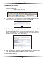
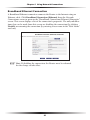
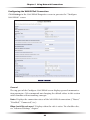
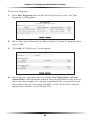
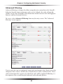
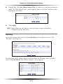
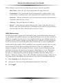
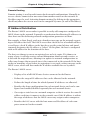
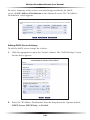
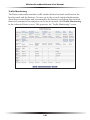
1
Wireless
Broadband
Router
User’s
Manual
MI424WR
Table of Contents
1 Introduction
1
Package Contents
Minimum System Requirements
Features
Getting to Know the Router
2 Connecting the Router
1
2
2
4
9
Setting Up the Router
Computer Network Configuration
Configuring the Router
Home Page
9
11
13
15
3 Configuring My Network Settings
17
Accessing My Network
Using My Network
17
18
4 Creating a Wireless Network
Overview
Wireless Status
Basic Security Settings
Advanced Security Settings
Configuring a Wireless Windows XP Client
Connecting a Wireless Windows XP Client
25
25
26
28
30
38
40
5 Using Network Connections
45
Network (Home/Office)
Ethernet Connection
Coax Connection
Broadband Ethernet Connection
Coax Broadband Connection
WAN PPPoE/WAN PPPoE 2
46
51
54
57
62
68
6 Configuring the Router’s Security
75
General
Access Control
Port Forwarding
DMZ (Demilitarized Zone) Host
Port Triggering
Remote Administration
Static NAT
Advanced Filtering
Security Log
7 Using Parental Controls
Activating Parental Controls
Advanced Parental Controls
i
77
79
82
83
84
86
88
89
92
99
99
101
Wireless Broadband Router User Manual
8 Using Advanced Settings
Firmware Upgrade
Firmware Restore
Configuration File
System Settings
Date and Time
Scheduler Rules
Routing
IP Address Distribution
Diagnostics
Restoring Default Settings
Reboot the Router
MAC Cloning
ARP (Address Resolution Protocol) Table
Users
QoS
Local Administration
Remote Administration
Dynamic DNS
DNS Server
Network Objects
Universal Plug and Play (UPnP)
Protocols
9 Monitoring the Router
Router Status
Advanced Status
103
105
107
108
109
114
115
117
119
123
124
124
125
125
126
127
127
128
128
130
132
133
135
137
137
138
10 Troubleshooting
141
A Quality of Service
145
Traffic Priority
Traffic Shaping
145
149
B Specifications
161
General
Wireless Operating Range
LED Indicators
Environmental
ii
161
162
162
162
1
Introduction
Thank you for purchasing the Wireless Broadband Router. The Wireless
Broadband Router supports Multimedia over Coax Alliance (MoCA), a new networking standard that allows digital entertainment and information to be transmitted and distributed to multiple devices over coaxial cables. The Router also supports Ethernet and Wi-Fi networking, making it the most versatile router available.
If you want to take your home or office networking to the next level, the Wireless
Broadband Router is sure to be one of the keys to your success.
Package Contents
s
Wireless Broadband Router
s
Black Power cord
s
Yellow cable (Ethernet, 6 ft.)
s
White cable (Ethernet, 10 ft.)
s
Quick Start Guide
s
Installation Guide
s
User Manual CD
s
Wireless Networking Guide
s
Wall-mount template
1
Wireless Broadband Router User Manual
s
Wall-mount template
s
Vertical stand
s
Warranty
Minimum System Requirements
s
Computer with Ethernet capability
s
Microsoft Windows 98SE, Me, 2000, or XP; Mac OS 9 or greater; Linux/
BSD, Unix
s
Internet Explorer 5.0 or higher; Netscape Navigator 7.0 or higher
s
TCP/IP network protocol installed on each computer
Features
s
Supports multiple networking standards, including:
WAN - Ethernet and MoCA interfaces
LAN - 802.11g, 802.11b, Ethernet, and MoCA
s
Integrated wired networking with 4-port 10/100 Mbps Ethernet switch
and MoCA
s
Integrated wireless networking with 802.11g access point featuring:
802.11g enabled to support speeds up to 54 Mbps wirelessly
802.11b backward compatible, communicating with 802.11b wireless
products at speeds up to 11 Mbps
s
Enterprise-level security, including :
Fully customizable firewall with Stateful Packet Inspection
Content filtering with URL-keyword based filtering, parental control,
customizable filtering policies per computer, and E-mail notification
Denial of service protection against IP spoofing attacks, intrusion and
scanning attacks, IP fragment overlap, ping of death, and fragmentation
attacks
Event logging
2
Chapter 1 Introduction
Intrusion detection
MAC address filtering
NAT
DMZ hosting
Access control
Advanced wireless protection featuring WPA, WEP 64/128 bit encryption, 802.1x authentication, and MAC address filtering
ICSA certified
s
Other Features
DHCP server option
DHCP server/PPPoE server auto-detection
DNS server
LAN IP and WAN IP address selection
MAC address cloning
Port forwarding
PPPoE support
QoS support (end to end layer 2/3) featuring Diffserv, 802.1p/q prioritization, configurable upstream/downstream traffic shaping, random early
detection and pass-through of WAN-side DSCPs, PHBs, and queuing to
LAN-side devices
Remote management and secured remote management using HTTPS
Reverse NAT
Static NAT
Static routing
Time zone support
VLAN multicast support
VPN IPSec (VPN passthrough only)
3
Wireless Broadband Router User Manual
Getting to Know the Router
This section contains a quick description of the Router’s lights (LEDs), ports, etc.
The Router features several indicator lights on its front panel, and a series of ports
and switches on its rear panel.
Front Panel
The front panel of the Router features ten indicator lights: Power, WAN Ethernet,
WAN Coax, Internet, LAN Ethernet (4), LAN Coax, and Wireless.
Power Light
The Power light displays the Router’s current status. If the Power light glows
steadily green, the Router is receiving power and fully operational. When the
Power light flashes rapidly, the Router is initializing. If the Power light is not illuminated or glows red when the Power cord is plugged in and the Power switch is
turned on, the Router has suffered a critical error and technical support should
be contacted.
WAN Ethernet Light
The WAN Ethernet light illuminates when the Router is connected to the
Internet via Ethernet. If flashing, data traffic is passing across the port.
WAN Coax Light
The WAN Coax light glows steadily or flashes when the Router is connected to
the Internet via coaxial cable.
4
Chapter 1 Introduction
Internet Light
When the Internet light glows steadily green, the Router is connected to the ISP
(Internet Service Provider). If it glows amber, there is a physical connection to
the ONT (Optical Network Terminator), but authentication has not taken place
(i.e., no IP address is present).
LAN Ethernet Lights (1, 2, 3, 4)
The LAN Ethernet lights illuminate when the Router is connected to a local
network via one or more of its Ethernet ports. If flashing, data traffic is passing
across the port(s).
LAN Coax Light
The LAN Coax light glows steadily or flashes when the Router is connected to a
local network via its Coax port.
Wireless Light
The Wireless light illuminates when the Router’s wireless access point is turned
on. If flashing, data traffic is passing across the wireless connection.
5
Wireless Broadband Router User Manual
Rear Panel
The rear panel of the Router features seven ports (Coax, WAN Ethernet, LAN
Ethernet [4], and Power), as well as a Reset button and Power switch.
Coax Port
The Coax port connects the Router to the ISP or other devices using a
coaxial cable.
Reset Button
To restore the Router’s factory default settings, press and hold the Reset button
for approximately ten seconds. The reset process will start about ten seconds
after releasing the button. When the Router resets, all the lights on the front
panel turn off, and then some of the lights start flashing. The Router has completed its reset process when the Power light glows steadily green.
Do not unplug the Power cord from the Router durM Caution:
ing the reset process. Doing so may result in the loss of the
Router’s configuration information. If this occurs, reset the
Router again.
WAN Ethernet Port
The WAN Ethernet port connects the Router to the ISP using an Ethernet cable.
LAN Ethernet Ports (4)
The LAN Ethernet ports connect devices to the Router via Ethernet cables to create a local area network (LAN). The LAN Ethernet ports are 10/100 Mbps autosensing ports, and either a straight-through or crossover Ethernet cable can be
used when connecting devices to the ports.
6
Chapter 1 Introduction
Power Switch
The Power switch powers the Router on and off.
Power Port
The Power port connects the Router to an electrical wall outlet via the
Power cord.
7
Wireless Broadband Router User Manual
This page left intentionally blank.
8
Connecting the
Router
2
Connecting a computer or local network to the Wireless Broadband Router is a
simple procedure, varying slightly depending on the computer’s operating system
but designed to seamlessly integrate the Router with the computer or local network. Moreover, addition configuration to access the GUI is not required when taking advantage of Universal Plug-and-Play support in Windows XP.
The Windows default network settings dictate that in most cases, the setup procedure described in the “Computer Network Configuration” will be unnecessary.
For example, the default DHCP setting in Windows 2000 is “client,” requiring no
further modification.
However, we advise following the setup procedure described below to verify all communication parameters are valid and the physical cable connections are correct.
Setting Up the Router
There are three parts to setting up the Router: Connecting the Cables, Configuring
the Router, and Connecting Other Computers/Set Top Boxes.
Connecting the Cables
If a different router was being used, disconnect it. Remove
☞ Note:
all router components, including power supplies and cables,
since they will not work with the Wireless Broadband Router.
1. Get the Router and black Power cord from the box.
2. Plug the black Power cord in the black port on the back of the Router and
then into a power outlet.
3. Turn the Router on.
4. Make sure the Power light on the front of the Router is glows steadily green.
5. Plug the yellow Ethernet cable from the box into one of the four yellow
Ethernet ports on the back of the Router.
9
Wireless Broadband Router User Manual
6. Make sure the computer is powered on, then plug the other end of the yellow
Ethernet cable into an Ethernet port on the computer.
7. Make sure at least one of the Ethernet LAN lights on the front of the Router
glows steadily green. This may take a few moments.
8. The phone company previously installed a high-speed wall jack somewhere in
the house. Locate it and note its type (Ethernet or coaxial). If Ethernet, follow
steps 8a and 8b. If coaxial, follow steps 9a and 9b. Then, continue to step 10.
a) If connecting via Ethernet, get the white Ethernet cable from the box and
plug one end in the white port on the back of the Router.
b) Plug the other end of the white Ethernet cable into the high-speed
Ethernet jack.
9. a) If connecting via coaxial cable, get a coaxial cable and connect one end to
the red Coax port on the back of the Router.
b) Connect the other end of the coaxial cable to a coax jack.
10. Make sure the Ethernet WAN light (if connecting via Ethernet) or Coax WAN
light (if connecting via coaxial cable) on the front of the Router glows steadily
green. If connecting via coaxial cable, this may take a few minutes.
If the Ethernet WAN light or Coax WAN light does not
☞ Note:
illuminate, make sure the cable (Ethernet or coaxial) is connected properly at both ends.
10
Chapter 2 Connecting the Router
Computer Network Configuration
Each network interface on the computer should either be configured with a statically defined IP address and DNS address, or instructed to automatically obtain an
IP address using the Network DHCP server. The Router is set up, by default, with an
active DHCP server, and we recommend leaving this setting as is.
Configuring Dynamic IP Addressing
To set up a computer to use dynamic IP addressing:
Windows XP
1. Select Network Connections in the Control Panel.
2. Right-click Ethernet Local Area Connection, then click Properties.
3. In the “General” tab, select Internet Protocol (TCP/IP), then click
Properties.
4. The “Internet Protocol (TCP/IP) Properties” window appears.
5. Click the “Obtain an IP address automatically” radio button.
6. Click the “Obtain DNS server address automatically” radio button.
7. Click OK in the “(TCP/IP) Properties” screen, then click OK in the “Local
Area Connection Properties” screen to save the settings.
Windows 2000
1. Select Network and Dialing Connections in the Control Panel.
2. Right-click on the Ethernet connection’s icon, then click Properties.
3. Select Internet Protocol (TCP/IP) component, then click Properties.
4. The “Internet Protocol (TCP/IP) Properties” window appears.
5. Click the “Obtain an IP address automatically” radio button.
6. Click the “Obtain DNS server address automatically” radio button.
11
Wireless Broadband Router User Manual
Windows 98/Me
1. Select Network in the Control Panel.
2. Select the TCP/IP settings for the network card, then click Properties.
3. Click the “Obtain an IP address automatically” radio button in the “IP
Address” tab.
4. Click Disable DNS in the DNS configuration tab.
5. Click OK in the “TCP/IP Properties” screen.
6. Click OK in the “Network” screen to reboot and save the settings.
Windows NT
1. Click Network in the Control Panel. The “Network” window appears.
2. In the “Protocol” tab, select Internet Protocol (TCP/IP) then click
Properties.
3. In the “IP Address” tab, click the “Obtain an IP address automatically” radio
button.
4. In the “DNS” tab, verify no DNS server is defined in the “DNS Service Search
Order” text box and no suffix is defined in the “Domain Suffix Search
Order” text box.
Linux
1. Login into the system as a super-user, by entering “su” at the prompt.
2. Type “ifconfig” to display the network devices and allocated IPs.
3. Type “pump -i <dev>,” where <dev> is the network device name.
4. Type “ifconfig” again to view the newly allocated IP address.
5. Make sure no firewall is active on device <dev>.
12
Chapter 2 Connecting the Router
Configuring the Router
1. Open a web browser on the computer connected to the Router. In the
“Address” text box, type:
http://192.168.1.1
then press Enter on the keyboard.
2. The “Login” screen appears. Enter the default user name (admin) and password (password) in the appropriate text boxes, then click OK.
3. The “Login Setup” screen appears. Select a new user name and password and
enter them in the appropriate text boxes (the password must be entered twice,
for validation purposes). Write the new user name and password down on a
piece of paper and keep it in a safe place, since they will be needed to access
the Router’s MegaControl Panel™ in the future.
4. In the bottom part of the screen, select the correct time zone from the “Time
Zone” drop-down list, then click OK at the bottom of the screen.
The Router is now configured.
13
Wireless Broadband Router User Manual
Connecting Other Computers/Set Top Boxes
The Router can connect to other computers or set top boxes in three ways: via
Ethernet, via wireless connection, or via coaxial cable.
Ethernet
1. Get an Ethernet cable and plug one end into one of the open yellow
Ethernet ports on the back of the Router.
2. Plug the other end of the Ethernet cable into an Ethernet port on the computer.
3. Make sure the corresponding Ethernet LAN light on the front of the Router
glows steadily green.
4. Repeat these steps for each computer to be connected to the Router
via Ethernet.
Wireless
1. Make sure each computer to be connected wirelessly has built-in wireless or
an attached wireless adapter.
2. Make sure the computer uses the same ESSID and WEP key as the Router by
launching the computer’s wireless application
3. Enter the ESSID and WEP key found on the sticker on the bottom of the
Router in the computer’s wireless settings and click Save. Make sure to configure the computer to use 64/40-bit WEP encryption.
4. Make sure the changes were implemented by surfing the Internet from
the computer.
5. Repeat these steps for every other computer to be connected to the
Router wirelessly.
Coaxial
1. Make sure all set top boxes are turned off.
2. Disconnect any adapter currently connected to the coaxial jack in the room
where the Router is.
14
Chapter 2 Connecting the Router
3. Connect one end of the coaxial cable to the coaxial wall jack, and the other
end to the red Coax port on the back of the Router.
4. Power up the set top box.
5. Make sure the Coax LAN light on the front of the Router glows steadily
green. This may take a few minutes. When it does, the set top box is connected to the Router.
Home Page
After logging into the Router’s MegaControl Panel (see “Configuring the Router” at
the beginning of this chapter), the “Home” screen appears.
The Home screen has a “Main Menu” that occupies the top of the screen. Below
that, the screen is divided into three columns: “My Router,” “My Network,” and
“Action Zone.”
15
Wireless Broadband Router User Manual
Main Menu
The “Main Menu” contains links to all of the configuration options of the Router:
Wireless Setup (explained in chapter 4 of this manual), My Network (chapter 5),
Firewall (chapter 6), Parental Controls (chapter 7), Advanced (chapter 8), and
System Monitoring (chapter 9).
My Router
This section displays the status of the Router’s network and Internet connection.
A green light signifies the Router is connected; a yellow light means the Router is
attempting to connect; and a red light signifies the Router’s connection is down.
Broadband Connection
The “Broadband Connection” section of My Router displays the state of the
Router’s broadband connection (“Connected” or “Disconnected”) for the two
connection options (“Coax Status” and “Ethernet Status”), and the WAN IP
address of the broadband connection.
Quick Links
The “Quick Links” section of My Router contains a list of frequently accessed
settings, including “Change Wireless Settings,” “Change Login User Name &
Password,” “Enable Gaming,” and “Logout.”
My Network
The “My Network” section of the Home screen displays the connection type, name,
and IP address of all devices connected to the Router’s network. The icon associated
with the device will be displayed normally (signifying an active device) or shaded
(signifying the device has not been active for at least 60 seconds). The user can also
configure the basic settings of each device by clicking on its icon. These settings are
described in more detail in chapter 3, “Configuring My Network Settings.”
Action Zone
This section contains links to various Verizon Web sites, and other informational
links. Clicking on the icon above “Go to Internet Now” connects the user to the
home page configured on the user’s web browser.
16
Configuring My
Network Settings
3
Once the Wireless Broadband Router is physically connected and the MegaControl
Panel’s Home screen is displayed in a web browser, a list of the devices connected
to the Router’s network appears in the “My Network” section of the screen. From
here, some basic network settings can be configured.
Accessing My Network
To access My Network, click on “My Network” in the Home screen.
The “My Network” screen appears:
On the far right side of the screen, in the “Connected Devices” section, is list of the
devices currently connected to the network, listed by connection type and number. The rest of the screen contains the “My Network” section, which displays each
device connected to the network, and a series of configuration settings.
17
Wireless Broadband Router User Manual
Using My Network
Various settings can be accessed for a particular device, as follows.
Access Device
For devices that can be accessed (such as Internet cameras and networked hard
drives), locate it in the My Network column, then click Access Devices to use the
device over the network.
Access Shared Files
To access the shared files on a particular device, locate the device in the My
Network column, then click Access Shared Files. A list of shared files appears on
the screen.
Website Blocking
Clicking “Website Blocking” generates the “Parental Control” screen. For more
information about using parental controls, see chapter 7, “Using Parental
Controls.”
Block Internet Services
Internet services blocking is used to prevent a device on the network from accessing particular services on the Internet, such as receiving E-mail or downloading
from FTP sites. To set up Internet services blocking on a networked device, locate
the device in the My Network column, then click Block Internet Services. The
“Access Control” screen appears.
18
Chapter 3 Configuring My Network Settings
1. Click Add in the “Networked computer/Device” column. The “Add Access
Control Rule” screen appears.
2. If this access control rule applies to all networked devices, select “Any” from
the “Networked Computer/Device” list box. If this rule applies to certain
devices only, select “Specify Address” and click Add. Then, add a network
object (for more details about adding network objects, see the “Advanced
Settings” chapter of this manual).
3. Select the Internet protocol to be blocked from the “Protocol” drop-down list.
4. If this rule will be active all the time, select “Always” from the “When should this
rule occur?” drop-down list. If the rule will only be active at certain times select
“Specify Schedule” and click Add. Then, add a schedule rule (for more details
about schedule rules, see the “Advanced Settings” chapter of this manual).
Make sure the Router’s date and time settings for your time
☞Note:
zone are set correctly for schedule rules to function properly.
5. Click Apply to save the changes. The Access Control screen will display a summary of the access control rule.
To block a service that is not included in the list select
☞Note:
“Specify Protocol” from the Protocol drop-down menu. The “Edit
Service” screen appears. Define the service, then click Apply. The
service will then be automatically added to the top section of the
“Add Access Control Rule” screen, and will be selectable.
19
Wireless Broadband Router User Manual
The user may disable an access control and the service made available without
having to remove the service from the Access Control table. This may be useful to
make the service available only temporarily, with the expectation that the restriction will be reinstated later.
• To temporarily disable an access control clear the check box next to the network computer/device.
• To reinstate the restriction at a later time select the check box next to the
network computer/device.
• To remove an access restriction from the Access Control table click the
Remove button for the service. The service will be removed from the Access
Control table.
When Web Filtering is enabled,
☞Note:
blocked by access control.
HTTP services cannot be
Enable Application
Activating “Enable Application” (also known as port forwarding) allows the network to be exposed to the Internet in certain limited and controlled ways, enabling
some applications to work from the local network (game, voice, and chat applications, for example), as well as allowing Internet access to servers in the network. To
set this up on a networked device, locate the device in the My Network column,
then click Enable Applications. The “Port Forwarding” screen appears.
20
Chapter 3 Configuring My Network Settings
1. Click Add. The “Add Port Forwarding Rule” screen appears.
2. Enter the local IP address or the host name of the computer providing the service in the “Networked Computer/Device” text box. Note that only one local
network computer can be assigned to provide a specific service or application.
3. Select the Internet protocol to be provided from the “Protocol” drop-down
list.
4. To select a port to forward communications to (this is optional), select
“Specify” from the “Forward to Port” drop-down list, then, in the text box
that appears, enter the port number. If no port is identified, select “Same as
Incoming Port.”
5. If this port will be active all the time, select “Always” from the “When should this
rule occur?” drop-down list. If the rule will only be active at certain times select
“Specify Schedule” and click Add. Then, add a schedule rule (for more details
about schedule rules, see the “Advanced Settings” chapter of this manual).
6. Click Apply to save the changes.
Some applications, such as
,
,
, and 323,
☞Note:
require the support of special specific Application Level Gateway
FTP TFTP PPTP
H
(ALG) modules to work inside the local network. Data packets
associated with these applications contain information that allows
them to be routed correctly. An ALG is needed to handle these
packets and ensure they reach their intended destinations. The
Router is equipped with a robust list of ALG modules, enabling
maximum functionality in the local network.
The ALG is automatically assigned based on the destination port.
21
Wireless Broadband Router User Manual
View Device Details
To view information about a networked device, or to test a device’s connection,
locate the device in the My Network column, then click View Device Details. The
“Device Information” screen appears.
1. Click Test Connectivity. The “Diagnostics” screen appears.
2. Click Go. The Router runs a ping test, and the results are displayed in the
Diagnostics screen.
22
Chapter 3 Configuring My Network Settings
Rename This Device
To rename a networked device, locate the device in the My Network column, then
click Rename This Device. The “Rename Device” screen appears.
Enter the new name of the device in the “New Name” text box and, if needed,
select a new icon for the device from the “New Icon” drop-down list.
Timeout for Inactive Device
The amount of time a device continues to be displayed on the network after it has
been disconnected is configured in the “Timeout for Inactive Device” screen. To
display the screen, click Timeout for Inactive Device.
Select the timeout period from the “Timeout” drop-down list. After the device has
been disconnected for this amount of time, it will no longer be displayed in the
“My Network” column.
23
Wireless Broadband Router User Manual
This page left intentionally blank.
24
4
Creating a Wireless
Network
This chapter explains how to create a wireless network using the Wireless
Broadband Router, including accessing and configuring wireless security options.
Overview
The Wireless Broadband Router provides the user with wireless connectivity over
the 802.11b and g standards (the most common wireless standards). 802.11b has
a maximum data rate of 11 Mbps, while 802.11g has a maximum data rate of 54
Mbps. Both operate in the 2.4 GHz range.
The Router’s wireless feature is turned on, with wireless security activated, by default.
The level of security is 64/40-bit WEP, with a unique WEP key already entered. This
information is displayed on a sticker located on the bottom of the Router.
The Router integrates multiple layers of security. These include the IEEE 802.1x
port-based authentication protocol, RADIUS client, EAP-MD5, EAP-TLS, EAP-TTLS,
EAP-PEAP, Wired Equivalent Privacy (WEP), Wi-Fi Protected Access (WPA) and
firewall and VPN applications.
Connecting a Wireless Client
To connect a wireless client to the Router:
The following procedure assumes the Router’s default wire☞ Note:
less settings are intact. If they have been changed, use the new
ESSID
and wireless security settings. For more details, see the “Connecting
a Wireless Windows XP Client” section of this chapter.
1. In the wireless client’s configuration interface, enter the Router’s ESSID
(found on a sticker on the bottom of the Router’s case) in the appropriate
text box or field (this varies depending on the wireless client’s manufacturer).
2. Enter the Router’s WEP key (also found on the sticker on the bottom of the
Router’s case) in the wireless client’s configuration interface.
3. Save the changes and exit the wireless client’s configuration interface. The client should now detect and join the Router’s wireless network. If not, check the
wireless client’s documentation, or contact its manufacturer.
25
Wireless Broadband Router User Manual
Wireless Status
Clicking on the “Wireless Settings” icon in the Home screen generates the “Wireless
Status” screen, which displays the current status of the wireless connection.
Radio Enabled
Displays whether the Router’s wireless radio is active.
SSID
The SSID (Service Set Identifier) is the network name shared among all devices
on a particular wireless network. The SSID must be identical for all devices on the
wireless network. It is case-sensitive and must not exceed 32 characters. Make sure
the SSID is the same for all devices to be connected to the wireless network. The
Router comes from the factory with an SSID already entered and displayed here.
The default SSID can also be found on a sticker on the bottom of the Router.
Channel
Displays the channel to which the wireless connection is currently set. All devices
on the wireless network must be on the same channel to function correctly.
Security Enabled
Displays what kind of security is active on the wireless connection, and the security
encryption key.
26
Chapter 4 Creating a Wireless Network
SSID Broadcast
Displays whether the Router is broadcasting its SSID. If activated, the SSID of the
Router’s wireless network is broadcast wirelessly.
MAC Authentication
Displays whether the Router is using MAC (Media Access Control) address authentication to allow wireless devices to join the network.
Wireless Mode
Displays the types of wireless device that can join the network. Options include
802.11b, 802.11g, or Mixed (allows both 802.11b- and 802.11g-equipped wireless
devices to join the network).
Packets Sent/Received
Displays the number of packets sent and received since the Router’s wireless capability was activated.
27
Wireless Broadband Router User Manual
Basic Security Settings
To configure the Router’s wireless network for basic security, select “Basic Security
Settings” from the menu on the left side of any Wireless Settings screen. The “Basic
Security Settings” screen appears.
1. Click the “On” radio button to activate the Router’s wireless radio.
2. Enter the name of the wireless network in the “SSID” text box.
3. Select the channel at which the Router’s wireless radio communicates by
selecting it from the “Channel” drop-down list.
4. Click the “WEP” radio button to activate WEP (Wired Equivalent Privacy)
security on the wireless network.
28
Chapter 4 Creating a Wireless Network
5. Select a WEP security level from the “select a WEP Key” drop-down list
(options include “64/40 bit” or “128/104 bit”).
6. Enter the key code in the “Key Code” text box. Each character must be a letter
from A-F or a number from 0-9. If 64/40 bit was selected in step 5, enter 10
characters. If 128/104 was selected, enter 26 characters.
7. Write down the wireless settings displayed on the screen. Other wireless devices wishing to join the Router’s wireless network must use these same settings
when configuring the device’s wireless networking scheme.
8. Click Apply to save the settings.
29
Wireless Broadband Router User Manual
Advanced Security Settings
To configure the Router’s advanced wireless network security settings, select
“Advanced Security Settings” from the menu on the left side of any Wireless
Settings screen. The “Advanced Security Settings” screen appears.
The advanced settings should only be configured by experi☞ Note:
enced technical users.
Level 1 (Wireless Security)
This section is used to configure different types of wireless security. Select the type
of wireless security to apply to the wireless network by clicking the appropriate
radio button, then configure the security settings in the subsequent screens.
30
Chapter 4 Creating a Wireless Network
WEP
If WEP was selected in the Advanced Security Settings screen, the “WEP Key”
screen appears.
1. Select the appropriate network authentication level from the dropdown list. Options include Open System Authentication, Shared Key
Authentication, or Both.
2. Activate WEP key 1 by clicking the radio button next to “1” on the left side.
3. Select the length of key 1 by selecting “64/40 bit” or “128/104 bit” from the
appropriate drop-down list in the “Key Length” column.
4. Select the type of key from the appropriate drop-down list in the “Entry
Method” column. If “Hex” is selected, the key must be made up of hexadecimal digits. If “ASCII” is selected, the key can be made up of any characters.
5. Enter the key in the appropriate text box in the “Encryption Key” column.
If 64/40 bit was chosen in step 2, enter 10 characters. If 128/104 bit was chosen, enter 24 characters. Depending on what option was selected in step 3,
enter hexadecimal or ASCII characters.
6. Click Apply to save changes.
31
Wireless Broadband Router User Manual
802.1X WEP
If 802.1X WEP (Wired Equivalent Privacy) was selected, the “WEP+802.1x Radius
Settings” screen appears. To generate the full screen, click in the “Enabled” check
box to activate.
802.1x WEP is a robust security protocol that uses port control with dynamically
changing encryption keys automatically updated over the network. 802.11x WEP
uses a RADIUS (Remote Authentication Dial-in Service) server for authentication
purposes. This server must be physically connected to the Router. Also, the user
must enable the RADIUS client embedded in the Router (to do this, see chapter
9, “Advanced Settings”).
1. Click in the “Enabled” check box to enable WEP+802.1x security.
2. Enter the RADIUS server IP address in the “Server IP” text boxes.
3. Enter the RADIUS server’s port number in the “Server Port” text box.
4. Enter the RADIUS server’s shared secret in the “Shared Secret” text box.
5. Click Apply to save changes.
32
Chapter 4 Creating a Wireless Network
WPA
If WPA (Wi-Fi Protected Access) was selected, the “WPA Key”
screen appears.
1. Verify the authentication method selected is “Pre-Shared Key.”
2. Enter a phrase of at least eight characters in the “Pre-Shared Key” text box.
Verify that “ASCII” is selected in the associated drop-down list.
3. Select the proper encryption algorithm (TKIP or AES).
4. Click in the “Group Key Update Interval” check box to activate the group
key update interval, and set the interval time in the text box to the right.
5. Click Apply at the bottom of the screen to save changes.
33
Wireless Broadband Router User Manual
Level 2 (SSID Broadcast)
This section is used to configure the Router’s SSID broadcast capabilities.
Selecting “SSID Broadcast” generates the “SSID Broadcast” screen.
Click the “Enable” radio button to enable SSID broadcasting. If enabled, the SSID of
the Router’s wireless network will be broadcast wirelessly. To disable SSID broadcasting, click the “Disable” radio button.
34
Chapter 4 Creating a Wireless Network
Level 3 (Limiting Access)
This section is used to limit access to the Router’s wireless network.
Wireless MAC Authentication
Wireless MAC authentication allows the user to allow or deny access to the
Router’s wireless network by a particular device’s MAC address. Selecting
“Wireless MAC Authentication” from the Advanced Security Settings screen generates the “Wireless MAC Authentication” screen.
To set up wireless MAC authentication:
1. Click in the “Enable Access List” check box.
2. Select either “Accept all devices listed below” or “Deny all devices listed
below” by clicking the appropriate radio button. Selecting “Accept…” causes
all devices listed by MAC address to access the Router’s wireless network.
Selecting “Deny…” causes all listed devices to be denied access.
35
Wireless Broadband Router User Manual
3. Enter the MAC address of a device in the “Client MAC address” text box.
4. Click Add.
5. Repeat steps 3 and 4 to add more devices to the list.
6. When finished listing devices, click Apply.
To remove a MAC address, select it from the “List” list box, then click Remove.
802.11b/g Mode
This option allows the user to select the wireless communication standard compatible with the devices to be connected on the wireless network from the dropdown list. Options include 802.11b, 802.11g, or Mixed (allows both 802.11b
and 802.11g-equipped wireless devices to join the network).
Advanced Wireless Options
Clicking “Other Advanced Wireless Options” at the bottom of the Advanced
Security Settings screen generates the “Advanced Wireless Options” screen.
36
Chapter 4 Creating a Wireless Network
When should this rule occur?
Displays the time during which the rule is active. To configure schedule rules, see
chapter 9, “Advanced Settings.”
Network
Select the type of connection being configured from this drop-down list
(options: Network [Home/Office], Broadband Connection, or DMZ).
MTU
MTU (Maximum Transmission Unit) specifies the largest packet size permitted for Internet transmission. “Automatic” sets the MTU at 1500. Other choices
include “Automatic by DHCP,” which sets the MTU according to the DHCP connection, and “Manual,” which allows the user to set the MTU.
Transmission Rate
Select the wireless transmission rate from the drop-down list, or select “Auto”
to have the Router automatically select the best transmission rate. This setting
adjusts the bit rate of the Router’s wireless transmissions.
CTS Protection Mode
Activating CTS (Clear to Send) Protection Mode allows mixed 802.11b/g networks to operate at maximum efficiency. Select “Auto” from the drop-down list
to activate. Select “None” to deactivate .
Beacon Interval
Beacons are transmitted by the Router to help identify wireless networks. If beacons are transmitted too infrequently, networks may become hard to reach; if
too frequently, they become a resource waste. Enter the desired beacon interval
value (in milliseconds) in this text box.
37
Wireless Broadband Router User Manual
DTIM Interval
Enter the DTIM (Delivery Traffic Indication Message) interval value (in milliseconds) in this text box. A DTIM is a countdown mechanism for the Router,
informing wireless network clients of the next window for listening to broadcast
and multicast messages.
Fragmentation Threshold
Setting the correct fragmentation threshold can increase the reliability of frame
transmissions on the wireless network. Enter the fragmentation threshold in this
text box.
RTS Threshold
Enter the RTS (Request to Send) threshold in this text box. This setting controls
what size data packet the low level RF protocol issues to an
RTS packet.
Configuring a Wireless Windows XP Client
If the computer has wireless capabilities and is running Windows XP, it will automatically recognize this and create a wireless connection. View this connection
under Windows’ “Network Connections.”
The following description and images are in accordance
☞ Note:
with Microsoft Windows , Version 2002, running Service Pack
XP
2. If running another operating system, see the documentation
that came with the wireless adapter being used.
1. Click Network Connections in the Control Panel. The “Network
Connections” window appears.
38
Chapter 4 Creating a Wireless Network
2. Double-click the wireless connection icon. The “Wireless Network
Connection” screen appears, displaying all available wireless networks in the
vicinity. If the Router is connected and active, the Router’s wireless connection
is displayed. Note that the connection’s status is “Not connected” and defined
as “Security-enabled wireless network (WPA)” in the figure below.
3. Click the connection once to mark it, then click Connect at the bottom of the
screen. After the connection is established, its status will change to “Connected.”
An icon appears in the notification area, announcing the successful initiation
of the wireless connection.
4. Test the connection by disabling all other connections in the Network
Connections window and browsing the Internet.
The Router’s wireless network can now be accessed from the configured computer. However, any other user with a wireless-equipped device can also access the
wireless network. To prevent this, secure the wireless network, as explained in the
“Wireless Security” section of this chapter.
39
Wireless Broadband Router User Manual
Connecting a Wireless Windows XP Client
This section assumes the Router is set up with WPA security.
1. Click Network Connections in the Control Panel. The “Network
Connections” window appears.
2. Double-click the wireless connection icon. The “Wireless Network
Connection” screen appears, displaying the Router’s wireless connection. Note
that the connection is defined as “Security-enabled wireless network (WPA).”
40
Chapter 4 Creating a Wireless Network
3. Click the connection once to mark it, then click Connect at the bottom of
the screen. The following login window appears, asking for a “Network Key,”
which is the pre-shared key used when configuring the Router’s WPA security
(see the “WPA” section in this chapter).
4. Enter the pre-shared key in both text boxes and click Connect. After the connection is established, its status will change to “Connected,” as shown below.
An icon appears in the notification area, announcing the successful initiation
of the wireless connection.
5. Test the connection by disabling all other connections in the Network
Connections window and surfing the Internet.
If the login window shown in step 3 does not appear and the connection attempt
fails, configure the connection manually using the following procedure:
1. Click the connection once to mark it and then click Change Advanced
Settings in the “Related Tasks” box on the left part of the window.
41
Wireless Broadband Router User Manual
2. The “Wireless Network Connection Properties” window appears. Select
Wireless Networks.
3. Click the connection to highlight it, then click Properties. The connection’s
“Properties Window” appears.
4. From the “Network Authentication” drop-down list, select WPA-PSK.
5. From the “Data Encryption” drop-down list, select TKIP.
42
Chapter 4 Creating a Wireless Network
6. Enter the pre-shared key in both the “Network key” and the “Confirm network key” text boxes.
7. Click OK, then OK again.
8. When attempting to connect to the wireless network, the login window
appears, pre-populated with the pre-shared key. Press Connect to connect.
Since the network is now secured, only users who know the pre-shared key will be
able to connect. The WPA security protocol is similar to securing network access
using a password.
43
Wireless Broadband Router User Manual
This page left intentionally blank.
44
Using Network
Connections
5
The Wireless Broadband Router supports various local area network (LAN) and wide
area network (WAN, on Internet) connections via Ethernet or coaxial cables. Network
connections is used to configure the various parameters of the Router’s network and
Internet connections, and create new connections.
The settings covered in this chapter should be configMCaution:
ured by experienced network technicians only.
To access the Router’s network connections, in the “My Network” screen,
click Network Connections from the menu on the left side. The “Network
Connections” screen appears.
Click Advanced to expand the screen and display all connection entries.
45
Wireless Broadband Router User Manual
To select a connection, click on its name. The rest of this chapter describes the different network connections available on the Router, as well as the connection types
that can be created.
Network (Home/Office)
Select Network (Home/Office) in the Network Connections screen to generate
the “Network (Home/Office) Properties” screen. This screen displays a list of the
local network’s properties. The only modifications that can be made from this
screen are disabling the connection (by clicking Disable) or renaming the connection (by entering a new name in the “Rule Name” text box).
When a network is disabled, its formerly underlying
☞ Note:
devices will not be able to get the
address from the netDHCP
work interface to which they were connected.
The Network (Home/Office) connection is used to combine several network
devices under one virtual network. For example, a home/office network can be
created for Ethernet and other network devices.
46
Chapter 5 Using Network Connections
Configuring the Home/Office Network
Click Settings in the “Network (Home/Office) Properties” screen to generate the
“Configure Network (Home/Office)” screen.
General
The top part of the Configure Network (Home/Office) screen displays general
communication parameters. We recommend not changing the default values in
this section unless familiar with networking concepts.
Status Displays the connection status of the network.
When should this rule occur? Displays when the rule is active. To schedule rules,
see the “Advanced Settings” chapter.
Network Select the type of connection being configured from the drop-down list
(options: Broadband Connection, Network [Home/Office], or DMZ).
Connection Type Displays the type of connection.
Physical Address Displays the physical address of the network card used for the
network.
MTU MTU (Maximum Transmission Unit) specifies the largest packet size permitted for Internet transmission. “Automatic” sets the MTU at 1500. Other choices include “Automatic by DHCP,” which sets the MTU according to the DHCP
connection, and “Manual,” which allows the MTU to be set manually.
47
Wireless Broadband Router User Manual
Internet Protocol
This section has three options: No IP Address, Obtain an IP Address
Automatically, and Use the Following IP Address.
No IP Address Select this option if the connection will have no IP address. This is
useful if the connection operates under a bridge.
Obtain an IP Address Automatically Select this option if the network connection
is required by the ISP to obtain an IP address automatically. The server assigning
the IP address also assigns a subnet mask address, which can be overridden by
entering another subnet mask address.
Use the Following IP Address Select this option if the network connection uses a
permanent (static) IP address, then the IP address and subnet mask address.
Bridge
The “Bridge” section of the Configure Network (Home/Office) screen is used to
specify which networks can join the network bridge.
When a network is disabled, its formerly underlying
☞ Note:
devices inherit the network’s
settings. For example, the
DHCP
removal of a network configured as DHCP client automatically
configures the devices formerly constituting the network as
DHCP clients, with the exact DHCP client configuration.
Click in the check box next to the particular network to specify it. Make sure
there are no loops in the network configuration, and apply these settings in case
the network consists of multiple switches, or other bridges apart from those created by the Router.
Status The “Status” column displays the connection status of a particular device.
48
Chapter 5 Using Network Connections
STP Click in the device’s “STP” check box to enable Spanning Tree Protocol on
the device. This protocol provides path redundancy while preventing undesirable loops in the network.
Action The “Action” column contains an icon that, when clicked, generates the
configuration screen of the particular device.
DNS Server
Domain Name System (DNS) is the method by which website or domain names
are translated into IP addresses. Specify such an address manually, according to
the information provided by the ISP.
To manually configure DNS server addresses, select Use the Following DNS
Server Addresses. Specify up to two different DNS server addresses, one primary, the other secondary.
IP Address Distribution
The “IP Address Distribution” section of the Configure Network (Home/Office)
screen is used to configure the Router’s Dynamic Host Configuration Protocol
(DHCP) server parameters. DHCP automatically assigns IP addresses to network devices. If enabled, make sure to configure the network devices as “DHCP
Clients.” There are three options in this section: Disabled, DHCP Server, and
DHCP Relay.
Disabled Select this option if statically assigning IP addresses to the network
devices.
DHCP Server To set up the network bridge to function as a DHCP server:
1. Select DHCP Server.
2. Enter the IP address at which the Router starts issuing addresses in the
“Start IP Address” text boxes. Since the Router’s default IP address is
192.168.1.1, the Start IP Address should be 192.168.1.2.
3. Enter the end of the IP address range used to automatically issue IP addresses in the “End IP Address” text boxes. The “maximum” IP address that can
be entered here is 192.168.1.253.
49
Wireless Broadband Router User Manual
4. Enter the subnet mask address in the “Subnet Mask” text boxes. The subnet
mask determines which portion of a destination LAN IP address is the network portion, and which portion is the host portion.
5. If Windows Internet Naming Service (WINS) is being used, enter the WINS
server address in the “WINS Server” text boxes.
6. Enter the amount of time a network device will be allowed to connect to
the Router with its currently issued dynamic IP address in the “Lease Time
in Minutes” text box.
7. Click in the “Provide Host Name If Not Specified by Client” check box to
have the Router automatically assign network devices with a host name, in
case a host name is not provided by the user.
DHCP Relay Select this option to have the Router function as a DHCP relay, and
enter the IP address in the screen that appears.
Routing
The Router can be configured to use static or dynamic routing. Dynamic routing automatically adjusts how packets travel on the network, while static routing
specifies a fixed routing path to neighboring destinations.
There are two options in the “Routing” section of the Configure Network
(Home/Office) screen: Basic or Advanced.
Basic Select this option for basic routing operation.
Advanced To set up the Router’s network bridge for advanced routing:
1. Select Advanced from the “Routing” drop-down menu.
2. Enter a device metric in the “Device Metric” text box. The device metric is
a value used by the Router to determine whether one route is superior to
another, considering parameters such as bandwidth and delay time.
3. Click in the “Default Route” check box to define this device as a the
default route.
4. Click in the “Multicast - IGMP Proxy Internal” check box to activate
multicasting.
50
Chapter 5 Using Network Connections
Routing Table
Clicking New Route generates the “New Route” window, where a new route can
be configured.
Additional IP Addresses
Clicking New IP Address generates the “Additional IP Address Settings” screen,
where additional IP addresses can be created to access the Router via the
Network (Home/Office) connection.
Ethernet Connection
An Ethernet connection connects computers to the Router using Ethernet cables,
either directly or via network hubs and switches. Click Ethernet in the Network
Connections screen (if needed, click Advanced at the bottom of the screen to
reveal the “Ethernet” link below “Network [Home/Office]”) to generate the
“Ethernet Properties” screen. This screen displays a list of the connection’s properties. The only modifications that can be made from this screen are disabling the
connection (by clicking Disable) or renaming the connection (by entering a new
name in the “Rule Name” text box).
If disabling the connection, the Router must be rebooted
☞ Note:
for the change to take effect.
51
Wireless Broadband Router User Manual
Configuring the Ethernet Connection
Click Settings at the bottom-right of the Ethernet Properties screen to generate the
“Configure Ethernet” screen.
General
The top part of the Configure Ethernet screen displays general communication
parameters. We recommend not changing the default values in this section unless
familiar with networking concepts.
Status Displays the connection status of the Ethernet switch.
When should this rule occur? Displays when the rule is active. To schedule rules,
see the “Advanced Settings” chapter.
Network Select the type of connection being configured from the drop-down list
(Network [Home/Office], Broadband Connection, or DMZ).
Connection Type Displays the type of connection.
Physical Address Displays the physical address of the network card used for
the network.
MTU MTU (Maximum Transmission Unit) specifies the largest packet size permitted for Internet transmission. “Automatic” sets the MTU at 1500. Other choices include “Automatic by DHCP,” which sets the MTU according to the DHCP
connection, and “Manual,” which allows the MTU to be set manually.
52
Chapter 5 Using Network Connections
Additional IP Addresses
Clicking New IP Address generates the “Additional IP Address Settings” screen,
where additional IP addresses can be created to access the Router via the
Ethernet connection.
4 Ports Ethernet Switch
This section displays the connection status of the Router’s four Ethernet ports.
Clicking on a connection’s “Action” icon (in the column on the right) generates
the “Port VLANs” screen, where ingress and egress policies can be edited.
53
Wireless Broadband Router User Manual
Coax Connection
A Coax connection connects devices (such as set-top boxes) to the Router using
a coaxial cable. Click Coax in the Network Connections screen (if needed, click
Advanced at the bottom of the screen to reveal the “Coax” link below “Network
[Home/Office]”) to generate the “Coax Properties” screen. This screen displays a
list of the connection’s properties. The only modifications that can be made from
this screen are disabling the connection (by clicking Disable) or renaming the
connection (by entering a new name in the “Name” text box).
If disabling the connection, the Router must be rebooted
☞ Note:
for the change to take effect.
54
Chapter 5 Using Network Connections
Configure Coax
Click Settings at the bottom-right of the Coax Properties screen generates the
“Configure Coax” screen.
General
The top part of the Configure Coax screen displays general communication
parameters. We recommend not changing the default values in this section unless
familiar with networking concepts.
Status Displays the status of the coax connection.v
When should this rule occur? Displays when the rule is active. To schedule rules,
see the “Advanced Settings” chapter
Network Displays the type of network.
Connection Type Displays the type of connection.
Physical Address Displays the physical address of the network card used for the
network.
MTU MTU (Maximum Transmission Unit) specifies the largest packet size permitted for Internet transmission. “Automatic” sets the MTU at 1500. Other choices include “Automatic by DHCP,” which sets the MTU according to the DHCP
connection, and “Manual,” which allows the MTU to be set manually.
55
Wireless Broadband Router User Manual
Coax Link
Set up the coax link options in this section of the Configure Coax screen.
Options include Channel, Privacy, and Password.
Channel Select the Channel from the drop-down list (select from 1-6, or
“Automatic”).
Privacy Toggle “Privacy” by clicking in the “Enabled” check box. If Privacy is
activated, all devices connected via coaxial cable must use the same password.
We recommend leaving the Privacy option deactivated.
Password Enter the Coax Link password in this text box.
Additional IP Addresses
Clicking New IP Address generates the “Additional IP Address Settings” screen,
where additional IP addresses can be created to access the Router via the Coax
Link Ethernet connection.
Coax Connection Status
Click Go to LAN Coax Stats to generate the “Coax Connection Status” screen,
which gives an overview of all the devices connected to the Router via coaxial cable.
56
Chapter 5 Using Network Connections
Broadband Ethernet Connection
A Broadband Ethernet connection connects the Router to the Internet using an
Ethernet cable. Click Broadband Connection (Ethernet) from the Network
Connections screen to generate the “Broadband Connection (Ethernet) Properties”
screen. This screen displays a list of the connection’s properties. The only modifications that can be made from this screen are disabling the connection (by clicking
Disable) or renaming the connection (by entering a new name in the “Rule Name”
text box).
If disabling the connection, the Router must be rebooted
☞ Note:
for the change to take effect.
57
Wireless Broadband Router User Manual
Configuring the Broadband Ethernet Connection
Click Settings at the bottom-right of the Broadband Connection (Ethernet) Properties
window to generate the “Configure Broadband Connection (Ethernet)” screen.
General
The top part of the screen displays general communication parameters. We recommend not changing the default values in this section unless you are familiar with
networking concepts.
Status Displays the status of the Ethernet connection (“Down,” “Connected,”
etc.)
Schedule Displays when the rule is active. To configure rules, see the “Advanced
Settings” chapter.
Network Select the type of connection being configured from the drop-down list
(options: Network (Home/Office), Broadband Connection, or DMZ).
Connection Type Displays the type of connection. Since this is an Ethernet
Connection, “Ethernet” is displayed.
Physical Address Displays the physical address of the network card used for the
network.
58
Chapter 5 Using Network Connections
MTU MTU (Maximum Transmission Unit) specifies the largest packet size permitted for Internet transmission. “Automatic, sets the MTU at 1500. Other choices include “Automatic by DHCP,” which sets the MTU according to the DHCP
connection, and “Manual,” which allows the MTU to be set manually.
Internet Protocol
This section includes three options: No IP Address, Obtain an IP Address
Automatically, and Use the Following IP Address.
No IP Address Select this option if the connection has no IP address. This is useful if the connection is operating under a bridge.
Obtain an IP Address Automatically Select this option if the ISP requires the connection to obtain an IP address automatically. The server assigning the IP address
also assigns a subnet mask address, which can be overridden by clicking in the
“Override Subnet Mask” check box and entering another subnet mask address.
Additionally, the DHCP lease can be renewed and/or released by clicking on the
appropriate “DHCP Lease” button. The “Expires In” value displays how long until
the DHCP lease expires.
Use the Following IP Address Select this option if the connection uses a permanent (static) IP address. The ISP should provide this address, along with a subnet
mask address, default gateway address, and, optionally, primary and secondary
DNS server addresses.
DNS Server
The Domain Name System (DNS) is the method by which website or domain
names are translated into IP addresses. This connection can be configured to
automatically obtain a DNS server address, or such an address can be specified
manually, according to the information provided by the ISP.
To configure the connection to automatically obtain a DNS server address, select
Obtain DNS Server Address Automatically from the “DNS Server” drop-down
list. To manually configure DNS server addresses, select Use the Following DNS
Server Addresses. Specify up to two different DNS server addresses, one primary, the other secondary.
59
Wireless Broadband Router User Manual
IP Address Distribution
The “IP Address Distribution” section of the Configure Broadband Connection
(Ethernet) screen is used to configure the Router’s Dynamic Host Configuration
Protocol (DHCP) server parameters. DHCP automatically assigns IP addresses
to network devices. If enabled, make sure to configure the network devices
as “DHCP Clients.” There are three options in this section: Disabled, DHCP
Server, and DHCP Relay.
We strongly recommend leaving this setting
MCaution:
at “Disabled.”
Disabled Select this option if statically assigning IP addresses to the network
devices.
DHCP Server To set up the Router to function as a DHCP server:
1. Select DHCP Server.
2. Enter the IP address at which the Router starts issuing addresses in the
“Start IP Address” text boxes. Since the Router’s default IP address is
192.168.1.1, the Start IP Address must be 192.168.1.2 or higher.
3. Enter the end of the IP address range used to automatically issue IP addresses in the “End IP Address” text boxes.
4. Enter the subnet mask address in the “Subnet Mask” text boxes. The subnet
mask determines which portion of a destination LAN IP address is the network portion, and which portion is the host portion.
5. If a Windows Internet Naming Service (WINS) is being used, enter the
WINS server address in the “WINS Server” text boxes.
6. Enter the amount of time a network device will be allowed to connect to
the Router with its currently issued dynamic IP address in the “Lease Time
in Minutes” text box. Just before the time is up, the device’s user will need to
make a request to extend the lease or get a new IP address.
7. Click in the “Provide Host Name If Not Specified by Client” check box to
have the Router automatically assign network devices with a host name, in
case a host name is not provided by the user.
60
Chapter 5 Using Network Connections
Additionally, to add a new product or product family, click New IP Range in the
“Vendor Class ID” column below “IP Address Distriution According to DHCP Option
60 (Vendor Class Identifier).” This generates the “DHCP Server Pool Settings” screen.
Set the device name, IP range, and priority level in the appropriate text boxes, then
click Apply.
DHCP Relay Select this option to have the Router function as a DHCP relay. To
enter a new IP address for the relay, click New IP Address. The “DHCP Relay
Server Address” screen appears. Enter the new IP address in the appropriate
text boxes, then click Apply.
Routing
The Router can be configured to use static or dynamic routing. Dynamic routing automatically adjusts how packets travel on the network, while static routing
specifies a fixed routing path to neighboring destinations.
There are two options in the “Routing” section of the “Configure WAN Coax
Link Ethernet” screen: Basic or Advanced.
Basic Select this option for basic routing operation.
Advanced To set up the Router’s Broadband Ethernet connection for advanced
routing:
1. Select Advanced from the Routing drop-down menu.
2. Enter a device metric in the “Device Metric” text box. The device metric is
a value used by the Router to determine whether one route is superior to
another, considering parameters such as bandwidth and delay time.
61
Wireless Broadband Router User Manual
3. Click in the “Default Route” check box to define this device as a the
default route.
4. Click in the “Multicast - IGMP Proxy Internal” check box to activate
multicasting.
Routing Table
Clicking New Route generates the “New Route” window, where a new route can
be configured.
Internet Connection Firewall
Click in the “Enabled” check box to activate the Router’s firewall on the connection.
Additional IP Addresses
Clicking New IP Address generates the “Additional IP Address Settings” screen, where
additional IP addresses can be created to access the Router via the connection.
Coax Broadband Connection
A Coax Broadband connection connects the Router to the Internet using a coaxial
cable. Click Broadband Connection (Coax) in the Network Connections screen
to generate the “Broadband Connection (Coax) Properties” screen. This screen displays a list of the connection’s properties. The only modifications that can be made
from this screen are disabling the connection (by clicking Disable) or renaming
the connection (by entering a new name in the “Name” text box).
62
Chapter 5 Using Network Connections
If disabling the connection, the Router must be rebooted
☞ Note:
for the change to take effect.
Configuring the Coax Broadband Connection
Click Settings at the bottom of the Broadband Connection (Coax) Properties
screen to generate the “Configure Broadband Connection (Coax)” screen.
General
The top part of the screen displays general communication parameters. We recommend not changing the default values in this section unless you are familiar
with networking concepts.
Status Displays the status of the connection (“Down,” “Connected,” etc.).
When should this rule occur? Displays when the rule is active. To schedule rules,
see the “Advanced Settings” chapter.
63
Wireless Broadband Router User Manual
Network Displays the type of network to which the link is connected. Since this
is a broadband connection (connected to the Internet), “Broadband Connection
is displayed.
Connection Type Displays the type of connection. Since this is a coaxial connection, “Coax” is displayed.
Physical Address Displays the physical address of the network card used for the
network.
MTU MTU (Maximum Transmission Unit) specifies the largest packet size
permitted for Internet transmission. “Automatic” sets the MTU at 1500. Other
choices include “Automatic by DHCP,” which sets the MTU according to the
DHCP connection, and “Manual,” which allows the MTU to be set manually.
Coax Link
Check and configure the coax link connection in this section of the screen.
Channel Displays the channel frequency range of the coaxial connection. This
setting is not user configurable; it is for information only.
Privacy Toggle “Privacy” by clicking in the “Enabled” check box. If Privacy is
activated, all devices connected via coaxial cable must use the same password.
We recommend leaving the Privacy option deactivated.
Password Enter the Coax Link password here.
WAN Coax Connection Speeds
This section displays the Router’s Tx and Rx speeds (in Mbps).
Internet Protocol
This section includes three options: No IP Address, Obtain an IP Address
Automatically, and Use the Following IP Address.
No IP Address Select this option if the connection has no IP address. This is useful when the connection is operating under a bridge.
64
Chapter 5 Using Network Connections
Obtain an IP Address Automatically Select this option if the ISP requires the connection to obtain an IP address automatically. The server assigning the IP address
also assigns a subnet mask address, which can be overridden by clicking in the
“Override Subnet Mask” check box and entering another subnet mask address.
Additionally, the DHCP lease can be renewed and/or released by clicking on the
appropriate “DHCP Lease” button. The “Expires In” value displays how long until
the DHCP lease expires.
Use the Following IP Address Select if the WAN connection is configured using a
permanent (static) IP address. The ISP should provide this address, along with a
subnet mask address, default gateway address, and, optionally, primary and secondary DNS server addresses.
DNS Server
Domain Name System (DNS) is the method by which website or domain names
are translated into IP addresses. The connection can be set to automatically
obtain a DNS server address, or an address can be set manually, according to
information provided by the ISP.
To configure the connection to automatically obtain a DNS server address, select
Obtain DNS Server Address Automatically from the “DNS Server” drop-down
list. To manually configure DNS server addresses, select Use the Following DNS
Server Addresses. Specify up to two different DNS server addresses, one primary, the other secondary.
IP Address Distribution
The “IP Address Distribution” section of the Configure Broadband Connection
(Coax) screen allows the user to configure the Router’s Dynamic Host
Configuration Protocol (DHCP) server parameters. The DHCP automatically
assigns IP addresses to network devices. If enabled, make sure to configure the
network devices as “DHCP Clients.” There are three options in this section:
Disabled, DHCP Server, and DHCP Relay.
We strongly recommend leaving this setting
MCaution:
at “Disabled.”
Disabled Select this option if statically assigning IP addresses to the network
devices.
65
Wireless Broadband Router User Manual
DHCP Server To set up the WAN Coax Link Ethernet connection to function as a
DHCP server:
1. Select DHCP Server.
2. Enter the IP address at which the Router starts issuing addresses in the
“Start IP Address” text boxes. Since the Router’s default IP address is
192.168.1.1, the Start IP Address must be 192.168.1.2.
3. Enter the end of the IP address range used to automatically issue IP addresses in the “End IP Address” text boxes.
4. Enter the subnet mask address in the “Subnet Mask” text boxes. The subnet
mask determines which portion of a destination LAN IP address is the network portion, and which portion is the host portion.
5. If a Windows Internet Naming Service (WINS) is being used, enter the
WINS server address in the “WINS Server” text boxes.
6. Enter the amount of time a network device will be allowed to connect to
the Router with its currently issued dynamic IP address in the “Lease Time
in Minutes” text box. Just before the time is up, the device’s user will need to
make a request to extend the lease or get a new IP address.
7. Click in the “Provide Host Name If Not Specified by Client” check box to
have the Router automatically assign network devices with a host name, in
case a host name is not provided by the user.
DHCP Relay Select this option to have the Router function as a DHCP relay, and
enter the IP address in the screen that appears.
Routing
The Router can be configured to use dynamic routing. Dynamic routing automatically adjusts how packets travel on the network There are two options in the
“Routing” section of the Configure Broadband Connection (Coax) screen: Basic
or Advanced.
Do not use static routing unless instructed to do so
MbyWarning:
your .
ISP
Basic Select this option for basic routing operation.
66
Chapter 5 Using Network Connections
Advanced To set up the Router’s Coax broadband connection for advanced routing:
1. Select Advanced from the Routing drop-down list.
2. Enter a device metric in the “Device Metric” text box. The device metric is
a value used by the Router to determine whether one route is superior to
another, considering parameters such as bandwidth and delay time.
3. Click in the “Default Route” check box to define this device as the
default route.
4. Click in the “Multicast - IGMP Proxy Internal” check box to activate
multicasting.
Routing Table
Click New Route to generate the “New Route” window, where a new route can
be configured.
Additional IP Addresses
Click New IP Address to generate the “Additional IP Address Settings” screen, where
additional IP addresses can be created to access the Router via the connection.
67
Wireless Broadband Router User Manual
WAN PPPoE/WAN PPPoE 2
WAN Point-to-Point Protocol over Ethernet (PPPoE) relies on two widely accepted
standards: Point-to-Point Protocol and Ethernet. PPPoE enables Ethernet net-
worked computers to exchange information with computers on the Internet.
PPPoE supports the protocol layers and authentication widely used in PPP and
enables a point-to-point connection to be established in the normally multipoint
architecture of Ethernet. A discovery process in PPPoE determines the Ethernet
MAC address of the remote device in order to establish a session.
Click WAN PPPoE in the Network Connections screen to generate the “WAN
PPPoE Properties” screen. This screen displays a list of the connection’s properties. The only modifications that can be made from this screen are disabling the
connection (by clicking Disable) or renaming the connection (by entering a new
name in the “Name” text box).
68
Chapter 5 Using Network Connections
Configuring the WAN PPPoE Connection
Click Settings in the WAN PPPoE Properties screen to generate the “Configure
WAN PPPoE” screen.
General
The top part of the Configure WAN PPPoE screen displays general communication parameters. We recommend not changing the default values in this section
unless familiar with networking concepts.
Status Displays the connection status of the WAN PPPoE connection. (“Down,”
“Disabled,” “Connected,” etc.)
When should this rule occur? Displays when the rule is active. To schedule rules,
see “Advanced Settings” chapter.
69
Wireless Broadband Router User Manual
Network Select the type of connection being configured from the drop-down list
(Broadband Connection, Network (Home/Office), or DMZ).
Connection Type Displays the type of connection. Since this is PPPoE connection,
“PPPoE” is displayed.
MTU MTU (Maximum Transmission Unit) specifies the largest packet size
permitted for Internet transmission. “Automatic, sets the MTU at 1492. Other
choices include “Automatic,” which sets the MTU according to the connection to
the ISP, and “Manual,” which allows the MTU to be set manually.
Underlying Connection Specify the underlying connection above which the protocol initiates from the drop-down list, which displays all possible underlying devices.
PPP Configuration
Point-to-Point Protocol (PPP) is the most popular method for transporting
packets between the user and the ISP.
Service Name Specify the networking peer’s service name, if provided by the ISP,
in this text box.
On-Demand To use PPP on demand to initiate the point-to-point protocol session
only when packets are actually sent over the Internet, click in this check box. This
option should be active on a limited basis
Idle Time Before Hanging Up Enter the amount of idle time, in minutes, before the
PPP session automatically ends .
Time Between Reconnect Attempts In this text box, specify the duration between
PPP reconnect attempts, as provided by the ISP.
PPP Authentication
Point-to-Point Protocol (PPP) currently supports four authentication protocols: Password Authentication Protocol (PAP), Challenge Handshake
Authentication Protocol (CHAP), and Microsoft CHAP versions 1 and 2.
Select the authentication protocols the Router may use when negotiating with a
PPTP server in this section. Select all the protocols if no information is available
about the server’s authentication methods. Note that encryption is performed
only if Microsoft CHAP, Microsoft CHAP version 2, or both are selected.
Warning: The
Authentication settings should not be
Mchanged
unless instructed to do so by your .
PPP
ISP
70
Chapter 5 Using Network Connections
Login User Name Enter the user name (provided by the ISP) in this text box.
Login Password Enter the password (provided by the ISP) in this text box.
Support Unencrypted Password (PAP) Password Authentication Protocol (PAP)
is a simple, plain-text authentication scheme. The user name and password are
requested by the networking peer in plain-text. PAP, however, is not a secure
authentication protocol. Man-in-the-middle attacks can easily determine the
remote access client’s password. PAP offers no protection against replay attacks,
remote client impersonation, or remote server impersonation.
Support Challenge Handshake Authentication (CHAP) Click in this check box to
activate CHAP, a challenge-response authentication protocol that uses MD5 to
hash the response to a challenge. CHAP protects against replay attacks by using
an arbitrary challenge string per authentication attempt.
Support Microsoft CHAP Click in this check box if communicating with a peer
that uses Microsoft CHAP authentication protocol.
Support Microsoft CHAP Version 2 Select this check box if communicating with a
peer that uses Microsoft CHAP Version 2 authentication protocol.
PPP Compression
The PPP Compression Control Protocol (CCP) is responsible for configuring,
enabling, and disabling data compression algorithms on both ends of the pointto-point link. It is also used to signal a failure of the compression/ decompression mechanism in a reliable manner.
For each compression algorithm (BSD and Deflate), select one of the following
from the drop-down list:
Reject Selecting this option rejects PPP connections with peers that use the compression algorithm. If Reject is activated, throughput may diminish.
Allow Selecting this option allows PPP connections with peers that use the compression algorithm.
Require Selecting this option insures a connection with a peer using the compression algorithm.
71
Wireless Broadband Router User Manual
Internet Protocol
Select one of the following Internet Protocol options from the “Internet
Protocol” drop-down list:
Obtain an IP Address Automatically This option is selected by default. Change only
if required by the ISP. The server that assigns the Router with an IP address also
assigns a subnet mask. Override the dynamically assigned subnet mask by selecting
the “Override Subnet Mask” and entering a different subnet mask.
Use the Following IP Address Select this option to configure the Router to use a
permanent (static) IP address. The ISP should provide this address.
DNS Server
The Domain Name System (DNS) is the method by which website or domain
names are translated into IP addresses. The Router can be configured to automatically obtain a DNS server address, or the address can be entered manually,
according to the information provided by the ISP.
To configure the connection to automatically obtain a DNS server address, select
Obtain DNS Server Address Automatically from the “DNS Server” drop-down
list. To manually configure DNS server addresses, select Use the Following DNS
Server Addresses from the “DNS Server” drop-down list. Up to two different
DNS server addresses can be entered (Primary and Secondary).
Routing
Select Advanced or Basic from the “Routing” drop-down list. If Advanced is
selected, additional options appear, as listed below.
Routing Mode Select one of the following Routing modes:
• Route - Select this option to cause the Router to act as a router between
two networks.
• NAT - Select this option to activate Network Address Translation (NAT),
which translates IP addresses to a valid, public address on the Internet. NAT
adds security, since the IP addresses of the devices on the network are not
transmitted over the Internet. In addition, NAT allows many addresses to
exist behind a single valid address. Use the NAT routing mode only if the
local network consists of a single device, or collisions may occur if more than
one device attempts to communicate using the same port.
72
Chapter 5 Using Network Connections
• NAPT - Select this option to activate NAPT (Network Address and Port
Translation), which refers to network address translation involving the
mapping of port numbers and allows multiple machines to share a single IP
address. Use NAPT if the local network contains multiple devices, a topology
that necessitates port translation in addition to address translation.
Device Metric The device metric is a value used by the Router to determine
whether one route is superior to another, considering parameters such as bandwidth, delay, and more.
Default Route Click in this check box to define the connection as a the default
route.
Multicast - IGMP Proxy Default Click in this check box to enable the Router to issue
IGMP (Internet Group Management Protocol) host messages on behalf of hosts
the Router discovers through standard IGMP interfaces. IGMP proxy enables the
routing of multicast packets according to the IGMP requests of local network devices asking to join multicast groups.
Routing Table
Clicking New Route generates the “New Route” window, where a new route can
be configured.
Internet Connection Firewall
Click in the “Enabled” check box to activate the Router’s firewall on the WAN
PPPoE connection.
73
Wireless Broadband Router User Manual
This page left intentionally blank.
74
Configuring the
Router’s Security
6
The Wireless Broadband Router’s security suite includes comprehensive and robust
security services: Stateful Packet Inspection, a firewall, user authentication protocols, and password protection mechanisms. These features allow users to connect
their computers to the Internet and be protected from the security threats.
The Router’s firewall is the cornerstone of the Router’s security suite. It has been
exclusively tailored to the needs of the residential/office user and is pre-configured
to provide optimum security.
The firewall provides both the security and flexibility home and office users seek. It
provides a managed, professional level of network security while enabling the safe
use of interactive applications, such as Internet gaming and video-conferencing.
Additional features, including surfing restrictions and access control, can also be
configured locally through the Router’s MegaControl Panel, or remotely by a
service provider.
The firewall also supports advanced filtering, designed to allow comprehensive
control over the firewall’s behavior. Specific input and output rules can be defined,
the order of logically similar sets of rules can be controlled, and distinctions
between rules that apply to Internet and local network devices can be made.
75
Wireless Broadband Router User Manual
This chapter covers these Security features:
• General - select the security level for the firewall.
• Access Control - restrict access from the local network to the Internet.
• Port Forwarding - enable access from the Internet to specified services
provided by computers on the local network.
• DMZ Host - configure a network host to receive all traffic arriving at the
Router which does not belong to a known session.
• Port Triggering - define port triggering entries to dynamically open the
firewall for some protocols or ports.
• Remote Administration - enable remote configuration of the Router from
any Internet-accessible computer.
• Website Blocking - block network access to a certain hosts or websites on
the Internet.
• Static NAT - allow multiple static NAT IP addresses to be designated to
devices on the network.
• Advanced Filtering - control the firewall’s settings and rules.
• Security Log - view and configure the security log.
76
Chapter 6 Configuring the Router’s Security
General
The “General” screen is used to configure the Router’s basic security settings.
The firewall regulates the flow of data between the local network and the Internet.
Both incoming and outgoing data are inspected and then either accepted (allowed
to pass through the Router) or rejected (barred from passing through the Router)
according to a flexible and configurable set of rules. These rules are designed to
prevent unwanted intrusions from the outside, while allowing local network users
access to required Internet services.
The firewall rules specify what types of services available on the Internet can be
accessed from the local network and what types of services available in the local
network can be accessed from the Internet. Each request for a service the firewall
receives, whether originating in the Internet or from a computer in the local network, is checked against the firewall rules to determine whether the request should
be allowed to pass through the firewall. If the request is permitted to pass, all subsequent data associated with this request (a “session”) will also be allowed to pass,
regardless of its direction.
For example, when accessing a website on the Internet, a request is sent out to the
Internet for this site. When the request reaches the Router, the firewall identifies
the request type and origin (HTTP and a specific computer in the local network, in
this case). Unless the Router is configured to block requests of this type from this
computer, the firewall allows this request to pass out onto the Internet. When the
website is returned from the web server, the firewall will associate it with this session and allow it to pass, regardless of whether HTTP access from the Internet to
the local network is blocked or permitted.
77
Wireless Broadband Router User Manual
Note that it is the origin of the request, not subsequent responses to this request,
which determines whether a session can be established or not.
The Router features three pre-defined security levels: Minimum, Typical, and
Maximum. The table below summarizes the behavior of the Router for each of the
three security levels.
Requests from the Internet
(incoming traffic)
Requests from the local
network (outgoing traffic)
Maximum
Security
Blocked - No access to local
network from Internet,
except as configured in the
Port Forwarding, DMZ host,
and Remote Access screens.
Limited - Only commonly
used services, such as web
browsing and E-mail, are
permitted.
Typical Security
Blocked - No access to local
network from Internet,
except as configured in the
Port Forwarding, DMZ host,
and Remote Access screens.
Unrestricted - All services
are permitted, except as
configured in the Access
Control screen.
Minimum
Security
Unrestricted - Permits full
access from Internet to local
network; all connection
attempts permitted.
Unrestricted - All services
are permitted, except as
configured in the Access
Control screen.
Security Level
These services include Telnet, FTP, HTTP, HTTPS, DNS, IMAP, POP3 and SMTP.
Some applications (such as some Internet messengers and
☞Note:
Peer-To-Peer client applications) tend to use these ports if they
cannot connect with their own default ports. When applying
this behavior, these applications will not be blocked outbound,
even at the Maximum Security level.
To configure the Router’s security settings:
1. From the General screen, select a security level by clicking the appropriate radio
button. Using the Minimum Security setting may expose the local network to
significant security risks, and thus should only be used for short periods of time.
78
Chapter 6 Configuring the Router’s Security
2. Check the “Block IP Fragments” box to protect the local network from a common type of hacker attack that uses fragmented data packets to sabotage the
network. Note that VPN over IPSec and some UDP-based services make legitimate use of IP fragments. IP fragments must be allowed to pass into the local
network to use these services.
3. Click Apply to save changes.
Access Control
Access control is used to block specific computers within the local network (or even
the whole network) from accessing certain services on the Internet. For example,
one computer can be prohibited from surfing the Internet, another computer from
transferring files using FTP, and the whole network from receiving incoming E-mail.
Access control defines restrictions on the types of requests that can pass from the
local network out to the Internet, and thus may block traffic flowing in both directions. In the E-mail example given above, computers in the local network can be
prevented from receiving E-mail by blocking their outgoing requests to POP3 servers on the Internet.
Access control also incorporates a list of preset services in the form of applications
and common port settings.
79
Wireless Broadband Router User Manual
Allow or Restrict Services
To view and allow/restrict these services:
1. Select Access Control from the left side of any Security screen. The “Access
Control” screen appears.
The “Allowed” section is only visible when the firewall is
☞Note:
set to “Maximum.”
2. Click Add. The “Add Access Control Rule” screen appears.
To block a service, click Add in the “Blocked” section of
☞Note:
the Access Control screen. To allow outgoing traffic, click Add
in the “Allowed” section of the screen.
80
Chapter 6 Configuring the Router’s Security
3. If this access control rule applies to all networked devices, select “Any” from
the “Networked Computer/Device” list box. If this rule applies to certain
devices only, select “Specify Address” and click Add. Then, create and add
a network object (for more details about adding network objects, see the
“Advanced Settings” chapter of this manual).
4. Select the Internet protocol to be allowed or blocked from the “Protocol”
drop-down list.
5. If the rule will be active all the time, select Always from the “When should this
rule occur?” drop-down list. If the rule will only be active at certain times, select
Specify Schedule and click Add. Then, add a schedule rule (for more details
about schedule rules, see the “Advanced Settings” chapter of this manual).
6. Click Apply to save the changes. The Access Control screen will display a summary of the new access control rule.
To block a service not included in the list, select Specify
☞Note:
Protocol from the Protocol drop-down menu. The “Edit
Service” screen appears. Define the service, then click OK. The
service will then be automatically added to the top section of the
“Add Access Control Rule” screen, and will be selectable.
An access control can be disabled and the service made available without having
to remove the service from the Access Control table. This may be useful to make
the service available temporarily, with the expectation that the restriction will be
reinstated later.
• To temporarily disable an access control, clear the check box next to the service name.
• To reinstate the restriction at a later time, select the check box next to the
service name.
• To remove an access restriction from the Access Control table, click Remove
for the service. The service will be removed from the Access Control table.
81
Wireless Broadband Router User Manual
Port Forwarding
In its default state, the Router blocks all external users from connecting to or
communicating with the network, making it safe from hackers who may try to
intrude on the network and damage it. However, the network can be exposed to
the Internet in certain limited and controlled ways to enable some applications to
work from the local network (game, voice, and chat applications, for example) and
to enable Internet access to servers in the network. Port forwarding (sometimes
referred to as local servers) supports both of these functions.
To grant Internet users access to servers inside the local network, each service provided, as well as the computer providing it, must be identified. To do this:
1. Select Port Forwarding from the left side of any Security screen. The “Port
Forwarding” screen appears.
2. Click Add. The “Add Port Forwarding Rule” screen appears.
3. Enter the local IP address or the host name of the computer providing the
service in the “Networked Computer/Device” text box, or select them from the
drop-down list. Note that only one local network computer can be assigned to
provide a specific service or application.
82
Chapter 6 Configuring the Router’s Security
4. Select the Internet protocol to be provided from the “Protocol” drop-down
list. To see all options, select All Services.
5. Select a WAN connection type from the “WAN Connection Type” drop-down
list. We recommend selecting All Broadband Devices.
6. To select a port to forward communications to (this is optional), select Specify
from the “Forward to Port” drop-down list, then, in the text box that appears,
enter the port number. If no port is identified, select Same as Incoming Port.
7. If this port will be active all the time, select Always from the “When should this
rule occur?” drop-down list. If the rule will only be active at certain times, select
Specify Schedule and click Add. Then, add a schedule rule (for more details
about schedule rules, see the “Advanced Settings” chapter of this manual).
8. Click Apply to save the changes.
How many computers can use a service or play a game simultaneously? Well, the
answer may be a bit confusing. All the computers on the network can behave as
clients and use a specific service simultaneously. Being a client means the computer within the network initiates the connection; for example, a computer on the
network can open an FTP connection with an FTP server on the Internet. But only
one computer on the network can operate as a server and respond to requests from
computers on the Internet (outside the local network).
DMZ (Demilitarized Zone) Host
The DMZ host feature allows one device on the network to operate outside the firewall. Designate a DMZ host:
• To use an Internet service, such as an online game or video-conferencing
program, not present in the Port Forwarding list and for which no port
range information is available.
• To expose one computer to all services without restriction or security.
A DMZ host is not protected by the firewall and may be
M Warning:
vulnerable to attack. Designating a DMZ host may also put other
computers in the local network at risk. When designating a DMZ
host, consider the security implications and protect it if necessary.
83
Wireless Broadband Router User Manual
To designate a local computer as a DMZ host:
1. Select DMZ Host from the left side of any Security screen. The “DMZ Host”
screen appears.
2. Click in the “DMZ Host IP Address” check box, then enter the IP address of the
computer to be designated as a DMZ host. Note that only one network computer can be a DMZ host at any time.
3. Click Apply.
Click in the “DMZ Host IP Address” check box again to disable the DMZ host.
Port Triggering
Port triggering can be used for dynamic port forwarding configuration. By setting
port triggering rules, inbound traffic is allowed to arrive at a specific network host
using ports different than those used for the outbound traffic. The outbound traffic triggers which ports inbound traffic is directed.
For example, a gaming server is accessed using UDP protocol on port 2222. The
gaming server responds by connecting the user using UDP on port 3333 when
starting gaming sessions. In this case, port triggering must be used, since it conflicts with the following default firewall settings:
• The firewall blocks inbound traffic by default.
• The server replies to the Router’s IP, and the connection is not sent back to
the host, since it is not part of a session.
To resolve the conflict, a port triggering entry must be defined, which allows
inbound traffic on UDP port 3333, only after a network host generated traffic to
UDP port 2222. This results in accepting the inbound traffic from the gaming
server, and sending it back to the network host which originated the outgoing traffic to UDP port 2222.
84
Chapter 6 Configuring the Router’s Security
To use port triggering:
1. Select Port Triggering from the left side of any Security screen. The “Port
Triggering” screen appears.
2. Select either “Specify Protocol” or “Show All Services” from the drop-down list
next to “Add.”
3. Click Add. An “Edit Service” screen appears.
4. Specify the port triggering entries by clicking New Trigger Ports and New
Opened Ports and entering the protocol and protocol number in the succeeding screens. For example, to set up port triggering for the scenario laid out on
the previous page, the service ports would be set to UDP and 2222, while the
opened ports would be set to UDP and 3333.
85
Wireless Broadband Router User Manual
Remote Administration
The Router can be accessed and controlled not only from within the local network,
but also from the Internet using remote adminstration.
To access, select Remote Administration from the left side of any Security screen.
The “Remote Administration” screen appears.
Telnet
Telnet is used to create a command-line session and gain access to all system settings and parameters using a text-based terminal. Select the Telnet port to be used
by clicking in the appropriate check box, then click Apply.
86
Chapter 6 Configuring the Router’s Security
MegaControl Panel
MegaControl Panel is used to obtain access to the Router’s MegaControl Panel and
gain access to all settings and parameters,using a web browser. Both secure (HTTPS)
and non-secure (HTTP) access is available. Select the port to be used by clicking in
the appropriate text box, then click Apply.
Telnet and MegaControl Panel remote administration
☞Note:
access may be used to modify or disable firewall settings. Local
IP addresses and other settings can also be changed, making
it difficult or impossible to access the Router from the local
network. Therefore, remote adminstration access to Telnet or
MegaControl Panel services should be activated only when
absolutely necessary.
Diagnostic Tools
Diagnostic Tools are used for troubleshooting and remote system management by a
user or the ISP.
Encrypted remote administration is performed using a
☞Note:
secure
connection, and requires an
certificate. When
SSL
SSL
accessing the Router for the first time using encrypted remote
administration, a warning appears regarding certificate authentication because the Router’s SSL certificate is self-generated. When
encountering this message under these circumstances, ignore it
and continue. Even though this message appears, the self-generated certificate is safe, and provides a secure SSL connection.
87
Wireless Broadband Router User Manual
Static NAT
This option allows multiple public addresses to be designated to devices on the
network. Static NAT allows devices behind a firewall and configured with private IP
addresses appear to have public IP addresses on the Internet. This allows an internal host, such as a web server, to have an unregistered (private) IP address and still
be reachable over the Internet. To do this:
1. Select Static NAT from any Security screen. The “Static NAT” screen appears.
2. Click Add. The “Add Static NAT” screen appears.
3. Enter the name of the computer to be used as the local host, or, to enter a
specific IP address, select Specify Address from the “Networked Computer/
Device” drop-down list and enter the IP address in the box on the right.
4. Enter a public IP address assigned by the ISP in the “Public IP Address”
text box.
5. Select a connection from the “WAN Connection Type” drop-down list.
6. Select the protocol that needs to be accessible from the public IP address by
clicking in the check box next to “Enable Port Forwarding for Static NAT,” then
selecting a protocol from the drop-down menu. Use “Any” to pass all data. Click
Apply, and Apply again.
Repeat these steps to add more static IP addresses from the network.
88
Chapter 6 Configuring the Router’s Security
Advanced Filtering
Advanced filtering is designed to allow comprehensive control over the firewall’s
behavior. Specific input and output rules can be defined, the order of logically
similar sets of rules controlled, and distinctions made between rules that apply to
Internet and local network devices.
To access, select Advanced Filtering from any Security screen. The “Advanced
Filtering” screen appears.
Two sets of rules can be configured: input rules and output rules. Each set of rules
comprises three subsets: initial rules, network devices rules, and final rules. These
subsets determine the sequence by which the rules will be applied. Following is a
description of the set ordering for inbound and outbound packets.
89
Wireless Broadband Router User Manual
Inbound Packets - Input Rule Sets
• Initial rules
• All rules defined for the network device on which the packet is
• Local servers rules from the local server tab in the security screen
• Rules to accept all the packets on a device in case the firewall check
box “Internet Connection Firewall” in the connection settings screen is
unchecked
• Remote administration rules from the remote administration tab
• DMZ host rules from the DMZ tab
• Final rules
Outbound Packets - Output Rules Sets
• Initial rules
• All rules defined for the network device on which the packet is
• Rules to accept all the packets on a device in case the firewall check
box “Internet Connection Firewall” in the connection settings screen is
unchecked
• IP/hostname filtering rules and access control rules from the tabs in the
security screen
• Final rules
There are numerous rules automatically inserted by the firewall in order to provide
improved security and block harmful attacks.
90
Chapter 6 Configuring the Router’s Security
To configure advanced filtering rules, click Add next to the rule title. The “Add
Advanced Filter” screen appears.
To add an advanced filtering rule, define the following rule parameters:
Matching
To apply a firewall rule, a match must be made between IP addresses or ranges
and ports. Use the “Source Address” and “Destination Address” drop-down lists to
define the coupling of source and destination traffic. Port matching will be defined
when selecting protocols. For example, if the FTP protocol is selected, port 21 will be
checked for matching traffic flow between the defined source and destination IPs.
Operation
This is where the action the rule will take is defined. Select one of the following
radio buttons:
• Drop - Deny access to packets that match the source and destination IP
addresses and protocol ports defined in “Matching.”
• Reject - Deny access to packets that match the source and destination IP
addresses and protocol ports defined in upper section of the screen, and
send an ICMP error or a TCP reset to the origination peer.
91
Wireless Broadband Router User Manual
• Accept - Allow access to packets that match the source and destination IP
addresses and protocol ports defined in upper section of the screen. The
data transfer session will be handled using Stateful Packet Inspection (SPI).
• Accept Packet - Allow access to packets that match the source and destination IP addresses and protocol ports defined in upper section of the
screen. The data transfer session will not be handled using Stateful Packet
Inspection (SPI), so other packets that match this rule will not be automatically allowed access. This setting is useful when creating rules that
allow broadcasting.
Logging
Click in this check box to add entries relating to this rule to the security log.
Scheduler (When should this rule occur?)
If advanced filtering needs to be active all the time, select “Always” from the “When
should this rule occur?” drop-down list. If the rule will only be active at certain times
select Specify Schedule and click Add. Then, add a schedule rule (for more details
about schedule rules, see the “Advanced Settings” chapter of this manual)
Security Log
The security log displays a list of firewall-related events, including attempts to
establish inbound and outbound connections, attempts to authenticate at an
administrative interface (MegaControl Panel or Telnet terminal), firewall configuration, and system start-up.
To access the security log, select Security Log from any Security screen. The
“Security Log” screen appears.
92
Chapter 6 Configuring the Router’s Security
Time
The time (based on the Router’s date and time settings) the event occurred.
Event
There are five kinds of events listed in the system log:
• Inbound Traffic - a result of an incoming packet
• Outbound Traffic - a result of an outgoing packet.
• Firewall Setup - configuration message
• WBM Login - a user logged in to WBM
• CLI Login - a user logged in to the command line interface via Telnet
Event-Type
Displays a textual description of the event.
Details
The “Details” column displays more information about the packet or the event,
such as protocol, IP addresses, ports, etc. The following are the available event types
that can be recorded in the security log:
• Firewall internal - from the firewall internal mechanism, in case this eventtype is recorded, an accompanying explanation will be added.
• Firewall status changed - the firewall changed status from up to down or
the vice versa, as specified in the event type description.
• STP packet - an STP (Spanning Tree Protocol) packet has been accepted/
rejected.
• Illegal packet options - the options field in the packet’s header is either
illegal or forbidden.
• Fragmented packet - a fragment has been rejected.
• WinNuke protection - a WinNuke attack has been blocked.
• ICMP replay - an ICMP (Internet Control Message Protocol) replay mes93
Wireless Broadband Router User Manual
sage has been blocked.
• ICMP redirect protection - an ICMP redirected message has been blocked.
• Packet invalid in connection - an invalid connection packet has been
blocked.
• ICMP protection - a broadcast ICMP message has been blocked.
• Broadcast/Multicast protection - a packet with a broadcast/multicast
source IP has been blocked.
• Spoofing protection - a packet from the Internet with a source IP belonging the local network has been blocked.
• DMZ network packet - a packet from a demilitarized zone network has
been blocked.
• Trusted device - a packet from a trusted device has been accepted.
• Default policy - a packet has been accepted/blocked according to the
default policy.
• Remote administration - a packet designated for the Router management
has been accepted/blocked.
• Access control - a packet has been accepted/blocked because of an access
control rule.
• Parental control - a packet has been blocked because of parental control.
• NAT out failed - NAT failed for this packet.
• DHCP request - the Router sent a DHCP request (depends on the distribution)
• DHCP response - the Router received a DHCP response (depends on the
distribution)
• DHCP relay agent - a DHCP relay packet has been received (depends on
the distribution)
• IGMP packet - an IGMP packet has been accepted.
• Multicast IGMP connection - a multicast packet has been accepted.
• PPTP connection - a packet inquiring whether the Router is ready to
94
Chapter 6 Configuring the Router’s Security
receive a PPTP connection has been accepted.
• AUTH:113 request - an outbound packet for AUTH protocol has been
accepted (for maximum security level).
• IPV6 over IPV4 - an IPv6 over IPv4 packet has been accepted.
• ARP - an ARP packet has been accepted.
• PPP Discover - a PPP discover packet has been accepted.
• PPP Session - a PPP session packet has been accepted.
• 802.1Q - a 802.1Q (VLAN) packet has been accepted.
• Outbound Auth1X - an outbound Auth1X packet has been accepted.
• IP Version 6 - an IPv6 packet has been accepted.
• Router initiated traffic - all traffic the Router initiates is recorded.
• Maximum security enabled service - a packet has been accepted because it
belongs to a permitted service in the maximum security level.
• SynCookies Protection - a SynCookies packet has been blocked.
• ICMP Flood Protection - a packet has been blocked, stopping an ICMP
flood.
• UDP Flood Protection - a packet has been blocked, stopping a UDP flood.
• Service - a packet has been accepted because of a certain service, as specified
in the event type.
• Advanced Filter Rule - a packet has been accepted/blocked because of an
advanced filter rule.
• Fragmented packet, header too small - a packet has been blocked because,
after defragmentation, the header was too small.
• Fragmented packet, header too big - a packet has been blocked because,
after defragmentation, the header was too big.
• Fragmented packet, bad align - a packet has been blocked because, after
defragmentation, the packet was badly aligned.
95
Wireless Broadband Router User Manual
• Fragmented packet, packet too big - a packet has been blocked because,
after defragmentation, the packet was too big.
• Fragmented packet, packet exceeds - a packet has been blocked because,
after defragmentation, the packet exceeded.
• Fragmented packet, no memory - a fragmented packet has been blocked
because there is no memory for fragments.
• Fragmented packet, overlapped - a packet has been blocked because, after
defragmentation, there were overlapping fragments.
• Defragmentation failed - the fragment has been stored in memory and
blocked until all fragments have arrived and defragmentation can be performed.
• Connection opened - debug message regarding connection.
• Wildcard connection opened - debug message regarding connection.
• Wildcard connection hooked - debug message regarding connection.
• Connection closed - debug message regarding connection.
• Echo/Chargen/Quote/Snork protection - a packet has been blocked due
to Echo/Chargen/Quote/Snork protection.
• First packet in connection is not a SYN packet - a packet has been blocked
due to a TCP connection that started without a SYN packet.
• Error : No memory - a new connection has not been established because of
lack of memory.
• NAT Error : connection pool is full. No connection created -a connection
has not been created because the connection pool is full.
• NAT Error: No free NAT IP - no free NAT IP, so NAT has failed.
• NAT Error: Conflict Mapping already exists - a conflict occurred because
the NAT mapping already exists, so NAT failed.
• Malformed packet: Failed parsing - a packet has been blocked because it is
malformed.
• Passive attack on ftp-server: Client attempted to open Server ports - a
packet has been blocked.
96
Chapter 6 Configuring the Router’s Security
• FTP port request to 3rd party is forbidden (Possible bounce attack) - a
packet has been blocked.
• Firewall Rules were changed - the firewall rule set has been modified.
• User authentication - a message arrived during login time, including both
successful and failed authentication.
Security Log Settings
To view or change the security log settings:
1. Click Settings in the Security Log screen. The “Security Log Settings” screen
appears.
2. Select the type of activities that will generate a log message:
• Accepted Incoming Connections - activating this check box generates a log
message for each successful attempt to establish an inbound connection to
the local network.
• Accepted Outgoing Connections - activating this check box generates a log
message for each successful attempt to establish an outgoing connection to
the public network.
97
Wireless Broadband Router User Manual
3. Select the type of blocked events to be listed in the log:
• All Blocked Connection Attempts - activating this check box generates
log messages for all blocked events.
• Other Blocked Events - if “All Blocked Connection Attempts” is unchecked, select specific blocked events from this list to generate log messages.
4. Click in the “Remote Administration Attempts” check box to write a log message for each remote-administration connection attempt, whether successful
or not.
5. Click in the “Connection States” check box to track connection handling by
the firewall and Application Level Gateways (ALGs).
6. Click Apply to save changes.
98
Using Parental
Controls
7
The abundance of harmful information on the Internet poses a serious challenge
for employers and parents alike - “How can I regulate what my employee/child
does on the Internet?” The Wireless Broadband Router’s Parental Controls allows
users to regulate, control, and monitor Internet access. By classifying and categorizing online content, it is possible to create numerous Internet access policies and
easily apply them to networked computers.
Activating Parental Controls
To create a basic access policy for a computer on the Router’s network, click Parental
Control from the top of the Home screen and follow these instructions:
1. The “Parental Control” screen appears. Click in the “Enable” check box to activate
the access policy mechanism.
2. Enter a “Rule Name” and “Description” for the access policy in the appropriate
text boxes.
99
Wireless Broadband Router User Manual
3a. Click the circle next to “Block the following Websites” to block access to a
list of websites, or click the circle next to “Allow the following Websites” to
allow access to a list of websites.
3b. Enter the URL of the websites to be included on the list in the text box below.
For example, enter “www.sample.com.”
3c. Additionally, the Router can block or allow access to websites based on “keywords.” For example, to block any website with “example” in its title, click in
the circle next to “Block the Following URL Keywords,” then enter “example”
in the text box below.
To allow access to any website with “example” in its title, click in the circle next
to “Allow the Following URL Keywords,” then enter “example” in the text box.
4. When finished, click Apply to have the access policy take effect.
100
Chapter 7 Parental Controls
5a. Select the computer or device on the network on which the access policy will
be enforced from the “Network Computer/Device” drop-down menu.
5a. Select the time period during which the access policy will be enforced from
the “Network Computer/Device” drop-down menu. If “Specify Schedule” is
selected, see “Scheduler Rules” in the “Advanced Settings” chapter for more
infomation.
6. An overview of the rule (or access policy) is displayed at the bottom of
the screen.
Advanced Parental Controls
Clicking Advanced from the menu on the left side generates the “Advanced” screen.
Here, all Internet access to a particular computer or device on the network can be
blocked. To do this:
1. Select the computer or device on the network on which the access policy will
be enforced from the “Network Computer/Device” drop-down menu.
101
Wireless Broadband Router User Manual
2. Select the time period during which the access policy will be enforced from
the “Network Computer/Device” drop-down menu. If “Specify Schedule” is
selected, see “Scheduler Rules” in the “Advanced Settings” chapter for more
infomation.
3. When finished, click Apply to have the access policy take effect.
4. An overview of the rule (or access policy) is displayed at the bottom of
the screen.
102
Using Advanced
Settings
8
The “Advanced” section of the Wireless Broadband Router’s MegaControl Panel is
intended primarily for more advanced users. Some changes to settings within this
section could adversely affect the operation of the Router and the local network,
and should be made with caution.
To access the Router’s Advanced Settings, click Advanced at the top of the Home
screen, which generates the “Advanced” screen.
The following settings are explained in this chapter:
Firmware Upgrade - download and install new versions of the Router’s firmware
Firmware Restore - restores firmware to previous version loaded in flash memory
Configuration File - manage configuration files
System Settings - modify the system’s settings
Date and Time - set the local date and time
Scheduler Rules - schedule firewall activation
Routing - manage routing policies
IP Address Distribution - manage the IP addresses of devices on the network
Diagnostics - perform diagnostic tests on the Router
103
Wireless Broadband Router User Manual
Restore Defaults - reset the Router to its default settings
Reboot Router - restart the Router
MAC Cloning - clone MAC addresses
ARP Table - display active devices and their IP and MAC addresses, etc.
Users - create and manage remote users
Local Administration - configure and manage local administration policies
Dynamic DNS - configure Dynamic DNS settings
DNS Server - manage the local (LAN) network for host name and IP address
Network Objects - create and manage network objects (discrete LAN subsets)
Universal Plug and Play - configure Universal Plug and Play settings
Protocols - manage and create open ports for various Internet protocols or customize an application
About - view information about the Router
Radius - manage the RADIUS (Remote Authentication Dial-in User Service) server
Remote Administration is explained in the “Security” chapter of this manual.
QoS is explained in Appendix A of this manual.
104
Chapter 8 Using Advanced Settings
Firmware Upgrade
The Router offers a built-in mechanism for upgrading its firmware without losing custom configurations and settings. There are two methods for upgrading the
firmware:
• Upgrading from a local computer - use a software image file pre-downloaded to the computer’s disk drive or located on the accompanying evaluation CD.
• Upgrading from the Internet - use this method to upgrade the Router’s
firmware by remotely downloading an updated software image file.
Upgrading From a Local Computer
To upgrade from a local computer:
1. Click Firmware Upgrade from the Advanced screen. The “Firmware
Upgrade” screen appears.
105
Wireless Broadband Router User Manual
2. In the “Upgrade From a Computer in the Network” section, click Upgrade
Now. The “Upgrade From a Computer in the Network” screen appears.
3. Enter the path of the software image file, or press the “Browse” button to
browse for the file, and click Apply. Make sure to only use files with an “rmt”
extension when performing the firmware upgrade procedure.
4. When loading is completed, a confirmation screen appears, asking whether
to upgrade to the new version. Click Apply. The upgrade process begins and
should take no longer than one minute to complete.
At the conclusion of the upgrade process the Router automatically reboots. The new
firmware will run, maintaining any custom configurations and settings.
Upgrading From the Internet
The Router’s firmware can be automatically updated via the Internet. From the
drop-down list next to the globe icon near the top of the Firmware Upgrade
screen, a list of options appears, as described below.
Automatically Check and Upgrade
If “Automatically Check for New Version and Upgrade Wireless Broadband
Router” is selected, enter the period of time the Router checks for a new
upgrade, and the URL at which to get the upgrade, in the appropriate text boxes.
The Router will then check at each time interval for upgrades and, if one is
available, upgrade the Router’s firmware.
Automatically Check and Send E-mail
If “Automatically Check for New Version and Notify via Email” is selected, enter
the period of time the Router checks for a new upgrade, and the URL at which
to get the upgrade, in the appropriate text boxes. The Router will then check at
each time interval for firmware upgrades and, if one is available, send an E-mail
to the E-mail address listed in the System Settings.
106
Chapter 8 Using Advanced Settings
Automatic Check Disabled
If “Automatically Check Disabled” is selected, the Router will not automatically
check for firmware upgrades.
Manual Checking and Upgrading
To manually upgrade the Router’s firmware:
1. Click Check Now in the Firmware Upgrade screen.
2. If a new version is available, click Force Upgrade. A download process will
begin. When downloading is completed, a confirmation screen appears, asking
whether to upgrade to the new version.
3. Click Apply. The upgrade process will begin and should take no longer than
one minute to complete.
At the conclusion of the upgrade process the Router automatically reboots. The new
firmware runs, maintaining any custom configurations and settings.
Firmware Restore
Firmware restore allows the Router’s firmware to return to an earlier version, if
the current version is unstable or does not meet specified needs. Click Firmware
Restore from the Advanced screen to generate the “Firmware Restore” screen.
The screen displays the “Active Firmware” and the “Backup Firmware.” To restore
the firmware to the backup firmware, click Restore Backup Firmware. A confirmation screen appears. Click OK to finish restoring the Router’s firmware.
107
Wireless Broadband Router User Manual
Configuration File
Use the Router’s Configuration File feature to view, save, and load configuration
files, which are used to backup and restore the Router’s current configuration: To
do this:
1. Click Configuration File in the Advanced screen. The “Configuration File”
screen appears.
2. Click Load Configuration File to load the previous configuration from a file
and restart the Router.
3. Click Save Configuration File to backup the current configuration to a file.
108
Chapter 8 Using Advanced Settings
System Settings
Clicking System Settings in the Advanced screen generates the “System Settings”
screen, where various system and management parameters can be configured.
109
Wireless Broadband Router User Manual
System
Use the “System” section of this screen to configure the following two options:
Wireless Broadband Router’s Hostname
Specify the Router’s host name by entering it into the this text box. The host
name is also the Router’s URL address, so it can be entered here rather than
192.168.1.1.
Local Domain
Specify the network’s local domain by entering it into this text box.
Wireless Broadband Router
Use this section to configure the following:
Automatic Refresh of System Monitoring Web Pages
Click in this check box to activate the automatic refresh of system monitoring
web pages.
Warn User Before Network Configuration Changes
Click in this check box to activate user warnings before network configuration
changes take effect.
Session Lifetime
After the Router has been inactive for a period of time, the user must reenter a
user name and password to continue accessing the MegaControl Panel. To change
the length of this time period, enter the amount of time (in seconds) in the
“Session Lifetime” text box.
Configure a number of concurrent users…
Used to limit the number of users that can access the Router at the same time.
Select the number of users from the drop-down list.
110
Chapter 8 Using Advanced Settings
Management Application Ports
This section allows the following management application ports to have their
default port numbers to be changed:
• Primary/secondary HTTP ports
• Primary/secondary HTTPS ports
• Primary/secondary Telnet ports
• Secure Telnet over SSL ports
System Logging
Use this section to configure the following system log options.
Enable Logging
Click in this check box to activate system logging.
Low Capacity Notification Enabled
Click in this check box to activate low capacity notification (works in tandem
with “Allowed Capacity Before Email Notification” and “System Log Buffer Size”
options).
Allowed Capacity Before Email Notification
Enter the percentage of system log buffer capacity reached to trigger an E-mail
notification.
System Log Buffer Size
Enter the size of the system log buffer in this text box.
Remote System Notify Level
This feature is used to specify the type of information received for remote system
logging. Options include None, Error, Warning, and Information.
111
Wireless Broadband Router User Manual
Security Logging
Use this section to configure the following security log options.
Enable Logging
Click in this check box to activate security logging.
Low Capacity Notification Enabled
Click in this check box to activate low capacity notification (works in tandem
with “Allowed Capacity Before Email Notification” and “Security Log Buffer
Size” options).
Allowed Capacity Before Email Notification
Enter the percentage of security log buffer capacity reached to trigger an E-mail
notification.
Security Log Buffer Size
Enter the size of the security log buffer in this text box.
Remote System Notify Level
This feature is used to specify the type of information received for security logging. Options include None, Error, Warning, and Information.
Outgoing Mail Server
Use this section to configure the outgoing mail server options. This server is used
format and send system and security log E-mail notifications.
Server
Enter the host name of the outgoing (SMTP) server in this text box.
From Email Address
E-mail notifications require a “from” address. Enter a “from” E-mail address in
this text box.
112
Chapter 8 Using Advanced Settings
Port
Enter the port number of the E-mail server in this text box.
Server Requires Authentication
If the E-mail server requires authentication, click in this check box, then enter a user
name and password in the “User Name” and “Password” text boxes that appear.
Auto WAN Detection
When activated, Auto WAN Detection causes the Router to automatically search for
a WAN connection.
Enable Logging
Clicking in this check box activates automatic WAN detection.
PPP Timeout
Enter the amount of time (in seconds) before the Router stops attempting to
establish a broadband PPP connection.
DHCP Timeout
Enter the amount of time (in seconds) before the Router stops attempting to
establish a broadband DHCP connection.
Number of Cycles
Enter the number of times the Router attempts to detect a broadband PPP and
DHCP connection.
Auto Detection Continuous Trying
Click in this check box to cause the Router to indefinitely search for a
broadband connection.
113
Wireless Broadband Router User Manual
Date and Time
To configure date, time, and daylight savings time settings perform the following:
1. Click Date and Time in the Advanced screen. The “Date and Time” screen
appears.
2. Select the local time zone from the drop-down list. The Router can automatically detect daylight saving setting for selected time zones. If the daylight saving settings for a time zone are not automatically detected, the following fields
will be displayed:
• Enabled - Select this check box to enable daylight saving time.
• Start - Date and time when daylight saving starts.
• End - Date and time when daylight saving ends.
• Offset - The time amount daylight saving time changes.
114
Chapter 8 Using Advanced Settings
To perform an automatic time update:
1. Click in the “Enabled” check box in the “Automatic Time Update” section.
2. Select the protocol to be used to perform the time update by selecting either
the “Time of Day” or “Network Time Protocol” radio button.
3. Specify how often to perform the update in the “Update Every” text box.
4. Define time server addresses by clicking Add on the bottom of the “Automatic
Time Update” section and entering the IP address or domain name of the time
server in the “Time Server Settings” screen.
Scheduler Rules
Scheduler rules are used for limiting the activation of firewall rules to specific time
periods, either for days of the week, or for hours of each day.
To define a rule:
1. Make sure the Router’s date and time are set correctly. To do this, see the “Date
and Time” section in this chapter.
2. Click Scheduler Rules in the Advanced screen. The “Scheduler Rules” screen
appears.
115
Wireless Broadband Router User Manual
3. Click Add. The “Set Rule Schedule” screen appears.
4. Enter a name for the rule in the “Rule Name” text box.
5. Specify if the rule will be active or inactive during the designated time period
by clicking the appropriate “Rule Settings” radio button.
6. Click Add Rule Schedule. The “Edit Rule Schedule” screen appears.
7. Select or active or inactive days of the week by clicking in the appropriate
text boxes.
116
Chapter 8 Using Advanced Settings
8. If applicable, click New Hours Range Entry to define an active/inactive hourly
range. The “Edit Hour Range” screen appears. Enter a start and end time in the
appropriate text boxes.
9. Click Apply.
Make sure the Router’s date and time settings are properly
☞Note:
configured for the time zone.
Routing
Access the routing table rules by clicking Routing in the Advanced screen. The
“Routing” screen appears.
Routing rules can be added, edited, or deleted from the Routing screen. To add a
router, click New Route. The “Route Settings” screen appears.
117
Wireless Broadband Router User Manual
When adding a routing rule, the following parameters must be specified:
• Rule Name- Select the type of network from the drop-down list.
• Destination - The destination is the destination host, subnet address, network address, or default route. The destination for a default route is 0.0.0.0.
• Netmask - The network mask is used in conjunction with the destination to
determine when a route is used.
• Gateway - Enter the Router’s IP address.
• Metric - A measurement of the preference of a route. Typically, the lowest
metric is the most preferred route. If multiple routes exist to a given destination network, the route with the lowest metric is used.
IGMP Multicasting
The Router provides support for IGMP multicasting, which allows hosts connected
to a network to be updated whenever an important change occurs in the network. A
multicast is simply a message that is sent simultaneously to a pre-defined group of
recipients. When joining a multicast group, all messages addressed to the group will
be received by the user, much like when an E-mail message is sent to a mailing list.
IGMP multicasting enables UPnP capabilities over networks and may also be useful
when connected to the Internet through the Router. When an application running on a computer in the network sends out a request to join a multicast group,
the Router intercepts and processes the request. If the Router is set to “Minimum
Security” no further action is required. However, if the Router is set to “Typical
Security” or “Maximum Security,” the group’s IP address must be added to the
Router’s “Multicast Groups” screen. This will allow incoming messages addressed to
the group to pass through the firewall and on to the correct networked computer.
1. Select Routing in the Advanced screen.
2. Activate the “Internet Group Management Protocol” check-box.
3. Click Apply.
118
Chapter 8 Using Advanced Settings
Domain Routing
Domain routing is used in multi-router local network configurations. Normally, to
accesss a device connected to one router from another router on the network, its
IP address must be used. Activating domain routing (by clicking in the appropriate
check box) allows the user to access to the computer by name (as well as IP address).
IP Address Distribution
The Router’s DHCP server makes it possible to easily add computers configured as
DHCP clients to the network. It provides a mechanism for allocating IP addresses to
these hosts and for delivering network configuration parameters to them.
For example, a client (host) sends out a broadcast message on the network requesting an IP address for itself. The DHCP server then checks its list of available addresses and leases a local IP address to the host for a specific period of time and simultaneously designates this IP address as “taken.” At this point, the host is configured
with an IP address for the duration of the lease.
The host can choose to renew an expiring lease or let it expire. If it chooses to
renew a lease, it will also receive current information about network services, as
it did with the original lease, allowing it to update its network configurations to
reflect any changes that occurred since it first connected to the network. If the host
wishes to terminate a lease before its expiration, it can send a release message to the
DHCP server, which will then make the IP address available for use by others.
The Router’s DHCP server:
• Displays a list of all DHCP hosts devices connected to the Router.
• Defines the range of IP addresses that can be allocated in the network.
• Defines the length of time for which dynamic IP addresses are allocated.
• Provides the above configurations for each network device and can be configured and enabled/disabled separately for each network device.
• Can assign a static lease to a network computer so that it receives the same IP
address each time it connects to the network, even if this IP address is within
the range of addresses that the DHCP server may assign to other computers.
• Provides the DNS server with the host name and IP address of each computer connected to the network.
119
Wireless Broadband Router User Manual
To view a summary of the services currently being provided by the DHCP
server, click IP Address Distribution in the Advanced screen. The “IP Address
Distribution” screen appears.
Editing DHCP Server Settings
To edit the DHCP server settings for a device:
1. Click the appropriate icon in the “Action” column. The “DHCP Settings” screen
for the device appears.
2. Select the “IP Address Distribution” from the drop-down list. Options include
DHCP Server, DHCP Relay, or Disable.
120
Chapter 8 Using Advanced Settings
3. Complete the following fields:
• Start IP Address Range, End IP Address Range - determines the number
of hosts connected to the network in this subnet. “Start” specifies the first IP
address assigned in this subnet and “End” specifies the last IP address in
the range.
• Subnet Mask - used to determine to which subnet an IP address belongs. An
example of a subnet mask value is 255.255.0.0.
• WINS Server - The WINS (Windows Internet Naming Service) server
determines the IP address associated with a network device.
• Lease Time - each device will be assigned an IP address by the DHCP server
for a limited time (“Lease Time”) when it connects to the network. When
the lease expires, the server will determine if the computer has disconnected
from the network. If it has, the server may reassign this IP address to a
newly-connected computer. This feature ensures that IP addresses not in use
will become available for other computers on the network.
• Provide host name if not specified by client - when activated, the Router
assigns the client a default name if the DHCP client does not have a host name.
4. Click Apply to save the changes.
DHCP Connections
To view a list of computers currently recognized by the DHCP server, click
Connection List at the bottom of the IP Address Distribution screen. The “DHCP
Connections” screen appears.
121
Wireless Broadband Router User Manual
To define a new connection with a fixed IP address:
1. Click New Static Connection in the DHCP Connections screen. The “DHCP
Connection Settings” screen appears.
2. Enter a host name for this connection.
3. Enter the fixed IP address to assign to the computer.
4. Enter the MAC address of the computer’s network card.
5. Click the Apply to save changes.
A device’s fixed
☞Note:
cific network card’s
IP address is actually assigned to the speMAC address installed on the network com-
puter. If this network card is replaced, the device’s entry in the
DHCP Connections list must be updated with the new network
card’s MAC address.
To remove a host from the table, click the appropriate “Delete” icon in the
Action column.
122
Chapter 8 Using Advanced Settings
Diagnostics
The Diagnostics screen can assist in testing network connectivity. This feature
pings (ICMP echo) an IP address and displays the results, such as the number of
packets transmitted and received, round trip time, and success status.
To diagnose network connectivity:
1. Click Diagnostics from the Advanced screen. The “Diagnostics” screen
appears.
2. Enter the IP address or domain name to be tested in the “Destination” field.
3. Click Go.
4. In a few seconds, diagnostics statistics will be displayed. If no new information
is displayed, click Refresh.
123
Wireless Broadband Router User Manual
Restoring Default Settings
If the Router’s factory default settings need to be restored (to build a new network
from the beginning, for example), use the following procedure:
1. If needed click Save Configuration File to save the Router’s current configuration to a file. The Router’s current settings can then be reapplied (see
“Configuraton File” in this chapter for more information).
2. Click Restore Defaults. The Router will restart, and factory default settings
will be applied
All of the Router’s settings and parameters will be restored
☞Note:
to their default values after performing the Restore Default procedure. This includes the administrator password; a user-specified password will no longer be valid.
Reboot the Router
To reboot the Router:
1. Click Restart in the Advanced screen. The “Restart” screen appears.
2. Click OK to restart the Router. This may take up to one minute.
To reenter the MegaControl Panel after restarting the Router, click the web browser’s “Refresh” button.
124
Chapter 8 Using Advanced Settings
MAC Cloning
A MAC (Media Access Control) address is a unique hexadecimal code that identifies
a device on a network. All networkable devices have a MAC address. When replacing another network device with the Router, the installation process can be simplified by copying the MAC address of the existing computer to the Router. To do this:
1. Click MAC Cloning in the Advanced screen. The “MAC Cloning” screen
appears.
2. Enter the MAC address to be cloned in the “To Physical Address” text boxes.
3. Click Clone My MAC Address to capture the MAC address of the computer currently accessing the MegaControl Panel. The Router will now have the new
MAC address.
ARP (Address Resolution Protocol) Table
Clicking ARP Table in the Advanced screen generates the “ARP Table” screen. This
screen displays the IP and MAC addresses of each DHCP connection.
125
Wireless Broadband Router User Manual
Users
To manage individual users:
1. Click Users in the Advanced screen, which generates the “Users” screen.
2. Click New User, which generates the “User Settings” screen.
When adding a user, specify the following parameters:
• Full Name - The user’s full name.
• User Name - The name a remote user will use to access the home or office
network. This entry is case-sensitive.
• New Password/Retype New Password - The password for the user (and
enter again to confirm).
• Permissions - The level of access the user is allowed. Options include
Administrator or Limited.
126
Chapter 8 Using Advanced Settings
• E-mail Notification - E-mail notification can be used to receive indications
of system events for a predefined severity classification. The available types
of events are “System” or “Security” events. The available severity of events
are Error, Warning, and Information.
To configure E-mail notification for a specific user:
1. Make sure an outgoing mail server has been configured in “System
Settings”. If not, click Configure Notification Mail Server to configure
the outgoing mail server.
2. Enter the user’s E-mail address in the “Notification Address” text box.
3. Select the “System” and “Security” notification levels in the “System
Notify Level” and “Security Notify Level” drop-down lists.
Changing any of the user parameters will prompt the con☞Note:
nection associated with the user to terminate. For changes to
take effect, activate the connection manually after modifying
user parameters.
QoS
The Router’s QoS (Quality of Service) capabilities are covered in detail in
Appendix A of this manual.
Local Administration
Clicking Administration in the Advanced screen generates the “Administration”
screen. This screen allows the user to allow local Telnet access using a particular
Telnet port.
To use, select a Telnet port by clicking in the appropriate check box, then
click Apply.
127
Wireless Broadband Router User Manual
Remote Administration
The Router’s Remote Administration capabilities are covered in detail in the
“Security” chapter of this manual.
Dynamic DNS
Dynamic DNS (Domain Name Server) a dynamic IP address to be aliased to a static
hostname, allowing a computer on the network to be more easily accessible from
the Internet. Typically, when connecting to the Internet, the service provider assigns
an unused IP address from a pool of IP addresses, and this address is used only for
the duration of a specific connection. Dynamically assigning addresses extends the
usable pool of available IP addresses, while maintaining a constant domain name.
This allows to user to access a device (a camera, for example) from a remote location, since the device will always have the same IP address.
When using Dynamic DNS, each time the IP address provided by the ISP changes,
the DNS database changes accordingly to reflect the change. In this way, even
though the IP address of the computer changes often, its domain name remains
constant and accessible.
Opening a Dynamic DNS Account
To use Dynamic DNS, a free Dynamic DNS account must be opened at http://
www.dyndns.org/account/create.html.
When applying for an account, a user name and password must be specified. Have
them available when customizing the Router’s Dynamic DNS feature. For more
information regarding Dynamic DNS, refer to http://www.dyndns.org.
128
Chapter 8 Using Advanced Settings
Setting up Dynamic DNS
To set up Dynamic DNS on the Router, click Dynamic DNS in the Advanced
screen. The “Dynamic DNS” screen appears.
Configure the following parameters:
Connection To Update
Select the connection with which to couple the Dynamic DNS service. Options
include Broadband Connection (Ethernet), Broadband Connection (Coax),
and WAN PPPoE.
Offline
Disable the Dynamic DNS feature by clicking this check box. This feature is
available only to users who have purchased some type of upgrade credit from
Dyndns.org. Note that changing the redirection URL can only be performed via
the Dynamic DNS website.
User Name
Enter the Dynamic DNS user name in this text box.
Password
Enter the Dynamic DNS password in this text box.
129
Wireless Broadband Router User Manual
Host Name
Enter the full Dynamic DNS domain in this text box.
Wildcard
Select the “Wildcard” check box to have any URL that includes the domain name
(here.yourhost.dyndns.org, for example) to connect.
Mail Exchanger
Enter the mail exchange server address. This will redirect all E-mails arriving at
the Dynamic DNS address to the mail server.
Backup MX
Select this check box to designate the mail exchange server to be a backup server.
DNS Server
The Domain Name System (DNS) translates domain names into IP addresses and
vice versa. The Router’s DNS server is an auto-learning DNS, which means that when
a new computer is connected to the network, the DNS server learns its name and
automatically adds it to the DNS table. Other network users can immediately communicate with this computer using either its name or its IP address.
The Router’s DNS also provides the following services:
• Shares a common database of domain names and IP addresses with the
DHCP server.
• Supports multiple subnets within the local network simultaneously.
• Automatically appends a domain name to unqualified names.
• Allows new domain names to be added to the database using the
MegaControl Panel.
• Permits a computer to have multiple host names.
• Permits a host name to have multiple IPs (needed if a host has multiple
network cards).
130
Chapter 8 Using Advanced Settings
The DNS server does not require configuration. However, the list of computers
known by the DNS can be viewed, the host name or IP address of a computer on
the list can be changed, or a new computer can be added to the list.
DNS Table
To view the list of computers stored in the DNS table, click DNS Server in the
Advanced screen. The “DNS Server” screen appears.
To add a new entry to the list:
1. Click Add DNS Entry in the DNS Server screen. The “DNS Entry” screen
appears.
2. Enter the computer’s host name in the “Host Name” text box.
3. Enter the computer’s IP address in the “IP Address” text boxes.
4. Click Apply to save the changes.
To edit the host name or IP address of an entry:
1. Click the appropriate “Edit” icon in the Action column. The “DNS Entry”
screen appears.
131
Wireless Broadband Router User Manual
2. If the host was manually added to the DNS Table, its host name and/or IP
address can be modified. Otherwise, only modify its host name.
3. Click Apply to save the changes.
To remove a host from the DNS table:
Click the appropriate “Delete” icon in the Action column. The entry will be
removed from the table.
Network Objects
Network objects is used to define a part of the Router’s network (a group of
computers, for example) by MAC addresses, IP addresses, and/or host names. The
defined part becomes a “network object,” and settings, such as configuring system
rules, can be applied to all the devices defined as part of the network object at once.
For example, instead of setting the same website filtering configuration to five computers one at a time, the computers can be defined as a network object, and website
filtering configuration can then be applied to all the computers simultaneously.
Network objects can be used to apply security rules based on host names instead
of IP addresses. This may be useful, since IP addresses change from time to time.
Moreover, it is possible to define network objects according to MAC addresses, making rule application more persistent against network configuration settings.
To define a network object:
1. Click Network Objects in the Advanced screen. The “Network Objects” screen
appears.
132
Chapter 8 Using Advanced Settings
2. Click Add. The “Edit Network Object” screen appears.
3. Specify a name for the network object in the “Description” text box.
4. Click Add. The “Edit Item” screen appears.
5. Select the type of network object type from the “Network Object Type” list box.
Options include IP address, IP Subnet, IP Range, MAC Address, and Host Name.
6. Repeat to create other network objects, if needed. When finished, click Apply
to save all created network objects.
Universal Plug and Play (UPnP)
To access the UPnP settings perform the following:
1. Click Universal Plug and Play in the Advanced screen. The “Universal Plug
and Play” settings screen appears.
133
Wireless Broadband Router User Manual
2. Click in the “Allow Other Network Users to Control Wireless Broadband
Router’s Network Features” check box to enable UPnP and allow UPnP services
to be defined on any of the network hosts.
3. Click in the “Enable Automatic Cleanup of Old Unused UPnP Services” check
box to enable automatic cleanup of invalid rules. When enabled, this feature
checks validity of all the UPnP services and rules every five minutes. Any old
and not used UPnP defined service is removed, unless any user defined rule
depends on it. Since there is a maximum limitation on the number of UPnP
defined services (256), enable the cleanup feature if the limit is in danger of
being exceeded.
4. Select whether all WAN connections, or only the main WAN connection, will
have UPnP active, from the “WAN Connection Publication” drop-down list.
UPnP services are not deleted when disconnecting a computer without proper shutdown of the UPnP application (e.g. messenger). Thus, if running a boingo, services
may often not be deleted, and will eventually lead to exhaustion of rules and services, and no new services can be defined. In this scenario, the cleanup feature will
find the invalid services and remove them, preventing services exhaustion.
134
Chapter 8 Using Advanced Settings
Protocols
Protocols features a list of preset and user-defined applications and common port
settings. Protocols can be used in various security features, such as Access Control
and Port Forwarding. New protocols can be added to support new applications or
existing ones can be edited when needed.
To define a protocol:
1. Click Protocols in the Advanced screen. The “Protocols” screen appears.
2. Click Add at the bottom of the screen. The “Edit Service” screen appears.
135
Wireless Broadband Router User Manual
3. Name the service in the “Service Name” text box and, if needed, enter a
description of the service in the “Service Description” text box, then click Add
Service Ports. The “Edit Service Server Ports” screen appears.
4. Select a protocol from the “Protocol” drop-down list. To create a new protocol,
select “Other.” After selecting a protocol, the screen will refresh, displaying the
relevant text boxes needed to edit the particular protocol.
5. Click Apply to save the changes.
136
Monitoring the
Router
9
The Wireless Broadband Router’s System Monitoring screens display important
system information, including:
• Basic Router settings
• System log
• Key network device parameters
• Network traffic statistics
Router Status
Click System Monitoring at the top of the Home screen to display the “Router
Status” screen, which displays the Router’s basic settings.
137
Wireless Broadband Router User Manual
Advanced Status
Clicking Advanced Status displays three other monitoring options: System
Logging, Full Status/System wide Monitoring of Connections, and Traffic
Monitoring.
System Logging
Click System Logging in the Advanced Status screen to generate the “System Log”
screen. The System Log displays a list of the most recent activities of the Router.
138
Chapter 9 Monitoring the Router
Full Status/System wide Monitoring of Connections
1. Click Full Status/System wide Monitoring of Connections in the Advanced
Status screen to generate the “Full Status/System wide Monitoring of
Connections” screen, which features a table summarizing the monitored connection data.
2. Click Refresh to update the table, or click Automatic Refresh On to constantly update the displayed parameters.
139
Wireless Broadband Router User Manual
Traffic Monitoring
The Router constantly monitors traffic within the local network and between the
local network and the Internet. To view up-to-the-second statistical information
about data received from and transmitted to the Internet, and about data received
from and transmitted to computers in the local network, click Traffic Monitoring
in the Advanced Status screen. This generates the “Traffic Monitoring” screen.
140
Troubleshooting
10
This chapter contains a list of problems that may be encountered while using the
Wireless Broadband Router, and techniques to try and overcome the problem.
Note that these techniques may not solve the problem (or problems).
Accessing the Router if Locked Out
If the Router’s connection is lost while making configuration changes, a setting
that locks access to the MegaControl Panel may have inadvertantly been activated. There are three common ways to lock access to the Router:
Scheduler If a schedule has been created that applies to the computer over the
connection being used, the Router will not be accessible during the times set in
the schedule. To regain access, either wait until the connection is scheduled to be
active again, or restore the default settings to the Router.
LAN Firewall If the firewall setting for the local network is set to maximum,
no computers from the network will be able to connect to the Router. To gain
access, restore the default settings to the Router.
Access Control If the access control setting for the computer is set to block the
computer, access to the Router will be denied. To gain access, restore the default
settings to the Router.
Restoring the Router’s Default Settings
There are two ways to restore the Router’s default settings. The first is to use the
tip of a ballpoint pen and depress the “Reset” button on the back of the Router
for at least five seconds. The second is to access the Router’s MegaControl Panel
and navigate to the “Advanced Settings” screen. Click on “Restore Defaults” and
read the instructions on-screen. Note that after performing either of these two
procedures, all previously saved settings on the Router will be lost.
141
Wireless Broadband Router User Manual
LAN Connection Failure
• Ensure the Router is properly installed, the LAN connections are correct,
and the power is on.
• Confirm the computer and Router are on the same network segment. If
unsure, let the computer get the IP address automatically by initiating the
DHCP function, then verify the computer is using an IP address within the
default range (192.168.1.2 through 198.168.1.254). If the computer is not
using an IP address within the range, it will not connect to the Router.
• Ensure the Subnet Mask address is set to 255.255.255.0.
Time out error occurs when entering a URL or IP Address
• Verify all the computers are working properly.
• Ensure the IP settings are correct.
• Ensure the Router is on and connected properly.
• Verify the Router’s settings are the same as the computer.
I’ve run out of Ethernet ports on my Router. How do I add more computers?
Plugging in an Ethernet hub or switch expands the number of ports on the
Router. Run a standard Ethernet cable from the “Uplink” port of the new hub or
switch to a yellow Ethernet port on the Router.
How do I change the password on the Router’s Graphic User Interface?
From the Router’s GUI Home screen, click Advanced, then Users. From the
“Users” screen, click Administrator, which generates the “User Settings” screen.
In the “General” section of the screen, change the password.
Is the wireless option on by default on the Router?
Yes. The Router’s wireless option is activated out of the box.
Is the wireless security on by default when the wireless option is activated?
Yes, with a unique 64-bit WEP (Wired Equivalent Privacy) key for each unit.
Which connection speeds does the Router support?
The Ethernet Internet connection supports 100 Mbps. The 802.11g wireless connection supports up to 54 Mbps (depending on signal quality, etc.). The MoCA
connection supports 270 Mbps.
142
Chapter 10 Troubleshooting
Are the Router’s Ethernet ports auto-sensing?
Yes. Either a straight-through or crossover Ethernet cable can be used.
Can I use an 802.11b wireless card to connect to the Router?
Yes, the Router can interface with 802.11b cards or 802.11g cards. The 802.11g
standard is backward compatible with the 802.11b standard. The Router can be
setup to handle just “g” wireless cards, just “b” wireless cards, or both.
Can my wireless signal pass through floors, walls, and glass?
The physical environment surrounding the Router can have a varying effect on
signal strength and quality. The more dense the object (a concrete wall compared to a plaster wall, for example), the greater the interference. Concrete or
metal-reinforced structures will experience a higher degree of signal loss than
those made of wood, plaster, or glass.
How do I find out what IP address my computer is using?
Windows 95, 98, 98SE, and Me - Select Start, Run, and type “winipcfg.” Press Enter.
When the “Winipcfg” window appears, ensure your network device is selected.
Windows NT, 2000, and XP - Select Start, Run and type “cmd.” Press Enter. When
the command screen appears, type “ipconfig” and press Enter.
My computer cannot connect to the Internet via MoCA. What should I do?
First, check the connection, and make sure all cables are connected correctly.
Then make sure the NIM is still connected, and check the Ethernet connection
to the NIM from the computer. A computer cannot be connected directly via a
MoCA cable; it must go through a NIM to connect. The NIM converts the MoCA
signal to an Ethernet signal the computer can understand.
I used DHCP to configure my network. Do I need to restart my computer to
refresh my IP address?
No. Follow these steps to refresh the IP address:
Windows 95, 98, 98SE, and Me - Select Start, Run, type “winipcfg,” and press
Enter. Ensure the Ethernet adapter is selected in the device box. Press the
Release_all button, then press the Renew_all button.
Windows NT 4.0 and 2000 - Select Start, Run, type “cmd,” and press Enter. At the
DOS prompt, type “ipconfig /release,” then type “ipconfig /renew.”
Windows XP - Unplug the Ethernet cable or wireless card and plug it back in.
143
Wireless Broadband Router User Manual
I cannot access the Router’s Graphical User Interface? What should I do?
If you cannot access the Router’s Graphical User Interface, make sure the computer connected to the Router is set up to dynamically receive an IP address.
I have an FTP or Web server on my network. How can I make it available to
users on the Internet?
For a Web server, enable port forwarding for port 8088 to the IP address of the
server and set up the Web server to receive on that port, as well. (Configuring
the server to use a static IP address is recommended.)
For an FTP server, enable port forwarding for port 21 to the IP address of the
server. (Configuring the server to use a static IP address is recommended.)
How many computers can be connected through the Router?
The Router is capable of 254 connections, but it is recommended to have no
more than 45 connections. As you increase the number of connections, you
decrease the available speed for each computer.
What is the default user name for the Router?
The default user name for the router is “admin” and the default password is
“password” (all lower case, no quotation marks). When logging into the Router
the first time (or after restoring the Router’s default settings), the user is asked to
create a new user name and password after entering the default user name and
password. Enter the new user name and password, write them down on a piece
of paper, and keep it in a safe place. The new user name and password will be
needed to access the User Interface in the future.
144
Quality of Service
A
Network-based applications and traffic are growing at a high rate, producing an
ever-increasing demand for bandwidth and network capacity. For obvious reasons,
bandwidth and capacity cannot be expanded infinitely, requiring that bandwidthdemanding services be delivered over existing infrastructure, without incurring
additional expensive investments. The next logical means of ensuring optimal
use of existing resources are Quality of Service (QoS ) mechanisms for congestion
management and avoidance.
Quality of Service refers to the capability of a network device to provide better service to selected network traffic. This is achieved by shaping the traffic and processing higher priority traffic before lower priority traffic.
Do not change any Quality of Service settings unless
ISTOP!
instructed to do so by the .
ISP
Traffic Priority
Traffic Priority manages and avoid traffic congestion by defining inbound and outbound priority rules for each device on the Router. These rules determine the priority that packets, traveling through the device, will receive. QoS parameters (DSCP
marking and packet priority) are set per packet, on an application basis.
QoS can be configured using flexible rules, according to the following parameters:
• Source/destination IP address, MAC address, or host name
• Device
• Source/destination ports
• Limit the rule for specific days and hours
The Router supports two priority marking methods for packet prioritization:
• DSCP
• 802.1p Priority
145
Wireless Broadband Router User Manual
The matching of packets by rules is connection-based, known as Stateful Packet
Inspection (SPI), using the Router’s firewall mechanism. Once a packet matches a
rule, all subsequent packets with the same attributes receive the same QoS parameters, both inbound and outbound. Connection-based QoS also allows inheriting
QoS parameters by some of the applications that open subsequent connections.
For instance, QoS rules can be defined on SIP, and the rules will apply to both control and data ports (even if the data ports are unknown). Applications that support
such inheritance have an ALG in the firewall. They are:
• SIP
• MSN Messenger/Windows Messenger
• TFTP
• FTP
• MGCP
• H.323
• Port triggering applications
• PPTP
• IPSec
146
Appendix A Quality of Service
Setting Priority Rules
To set priority rules:
1. Click Quality of Service in the Advanced screen. The “Traffic Priority” screen
appears. This screen is divided into two identical sections, one for “QoS input
rules” and the other for “QoS output rules,” which are for prioritizing the
inbound and outbound traffic, respectively. Each section lists all the devices on
which rules can be set. Rules can be set on all devices at once by clicking Add
in the “All Devices” row.
147
Wireless Broadband Router User Manual
2. After choosing the traffic direction and the device on which to set the rule, click
Add in the appropriate row. The “Add Traffic Priority Rule” screen appears.
Set the following parameters:
Source Address - The source address of the packets sent to or received from the
network object. To add an address:
1. Select Specify Address from the drop-down list. The screen refreshes and
an “Add” link appears.
2. Click Add, then add a new network object (see the “Advanced Settings”
chapter to learn how to add a network object). Clicking Add is the same as
clicking “New Entry” in the “Network Objects” screen.
Destination Address - The destination address of the packets sent to or
received from the network object. This address can be configured in the same
manner as the source address.
Protocol - Choose a specific traffic protocol from the drop-down list, or add a
new one. To add a new traffic protocol:
1. Select Specify Address from the drop-down list. The screen refreshes and
an “Add” link appears.
2. Click Add, and add a new protocol (see the “Advanced Settings” chapter to
learn how to add a protocol). Note that clicking Add is equivalent to clicking “New Entry” in the “Protocols” screen.
148
Appendix A Quality of Service
Set Priority - Activate this check box to add a priority to the rule. The screen will
refresh, allowing a selection between one of eight priority levels, zero being the
lowest and seven the highest (each priority level is mapped to low/medium/high
priority). This sets the priority of a packet on the connection matching the rule,
while routing the packet.
Set DSCP - Activate this check box to mark a DSCP value on packets matching
a connection that matches this rule. The screen will refresh, allowing the user to
enter the Hex value of the DSCP.
Log Packets Matched by This Rule - Check this check box to log the first packet
from a connection matched by this rule.
Schedule - By default, the rule will always be active. However, scheduler rules can
be configured to define time segments during which the rule may be active.
Traffic Shaping
Traffic Shaping is the solution for managing and avoiding congestion where the
network meets limited broadband bandwidth. Typical networks use a 100 Mbps
Ethernet LAN with a 100 Mbps WAN interface router. This is where most bottlenecks occur
A traffic shaper is essentially a regulated queue that accepts uneven and/or bursty
flows of packets and transmits them in a steady, predictable stream so that the network is not overwhelmed with traffic. While traffic priority allows basic prioritization of packets, traffic shaping provides more sophisticated definitions, such as:
• Bandwidth limit for each device
• Bandwidth limit for classes of rules
• Prioritization policy
• TCP serialization on a device
Additionally, QoS traffic shaping rules can be defined for a default device. These
rules will be used on a device that has no definitions of its own. This enables the
definition of QoS rules on the default WAN, for example, and their maintenance
even if the PPP or bridge device over the WAN is removed.
149
Wireless Broadband Router User Manual
Device Traffic Shaping
This section describes the different Traffic Shaping screens and terms, and presents
the feature’s configuration logic.
1. Click Quality of Service in the Advanced screen, then click Traffic Shaping.
The following screen appears.
2. Click Add. The “Add Device Traffic Shaping” screen appears.
3. Select the device for which the traffic will be shaped. The drop-down list
includes all the Router’s devices, as well as the option to select all devices in
each category (e.g., “All LAN Devices,” “All WAN Devices”). In this example,
select the default WAN device option.
4. Click Apply. The “Edit Device Traffic Shaping” screen appears.
150
Appendix A Quality of Service
Configure the following parameters:
Tx Bandwidth - Tx bandwidth limits the Router’s bandwidth transmission rate.
The purpose is to limit the bandwidth of the WAN device to that of the weakest outbound link.. This forces the Router to be the network bottleneck, where
sophisticated QoS prioritization can be performed.
Rx Bandwidth - In the same manner, this Rx bandwidth limits the Router’s
bandwidth reception rate.
TCP Serialization - Enable TCP Serialization from its drop-down list, either
for active voice calls only or for all traffic. The screen will refresh, adding a
“Maximum Delay” text box. This function allows the maximum allowed transmission time frame (in milliseconds) of a single packet to be defined. Any packet
requiring a longer time to be transmitted will be fragmented to smaller sections.
This avoids transmission of large, bursty packets that can cause delay or jitter for
real-time traffic, such as VoIP.
Shaping Classes
The bandwidth of a device can be divided to reserve constant portions of bandwidth to predefined traffic types. Such a portion is known as a shaping class. When
not used by its predefined traffic type or owner (for example VoIP), the class will
be available to all other traffic. However, when needed, the entire class is reserved
solely for its owner. Also, the maximum bandwidth that a class uses can be limited,
even if the entire bandwidth is available.
When a shaping class is defined for a specific traffic type, two shaping classes are
created. The second class is the “Default Class”, which is responsible for all the
packets that do not match the defined shaping class, or any other classes that might
be defined on the device. This can be viewed in the “Class Statistics” screen.
151
Wireless Broadband Router User Manual
To define a shaping class:
1. Click Add in the “Tx Traffic Shaping” section of the Edit Device Traffic
Shaping screen. The “Add Shaping Class” screen appears.
2. Name the new class and click Apply.
3. Click the class name to edit the shaping class. The “Edit Class” screen appears.
Configure the following parameters:
Name Enter the name of the class in this text box.
Class Priority The class can be granted one of eight priority levels, zero being the
highest and seven the lowest (opposite the rules priority levels). This level sets the
priority of a class in comparison to other classes on the device.
Tx Bandwidth Tx bandwidth is the reserved transmission bandwidth in kilobits
per second. The maximum allowed bandwidth can be limited by selecting Specify
from the drop-down list. The screen will refresh, adding another “Kbits/s” text
box. Enter the desired maximum allowed bandwidth.
Rx Bandwidth In the same manner, Rx bandwidth is the reserved reception
bandwidth, which can also be limited to a maximum allowed bandwidth.
152
Appendix A Quality of Service
Policy The class policy determines the policy of routing packets inside the class.
Select one of four options:
• Priority - Priority queuing utilizes multiple queues, so that traffic is distributed among queues based on priority. This priority is defined according to
packet’s priority, which can be defined explicitly, by a DSCP value, or by an
802.1p value.
• FIFO - The “First In, First Out” priority queue. This queue ignores any previously-marked priority the packets may have.
• Fairness - The fairness algorithm ensures no starvation by granting all packets a certain level of priority.
• RED - The RED (Random Early Detection) algorithm utilizes statistical
methods to drop packets in a “probabilistic” way before queues overflow.
Dropping packets in this way slows a source down enough to keep the queue
steady and reduces the number of packets lost when a queue overflows and a
host is transmitting at a high rate.
Schedule By default, the class will always be active. However, scheduler rules can
be configured to define time segments during which the class may be active.
Class Rules Class rules define which packets belong to the class. They must be
defined in order to associate packets that meet them with the shaping class.
Without class rules, the shaping class will have no effect. Each class can have outbound and/or inbound rules for outgoing and incoming traffic, respectively. For
example, all outgoing packets from computer A in the network can be defined
as belonging to the VoIP class. These packets will be limited to the class settings
(bandwidth, schedule, etc.). In addition, the traffic protocol and priority for each
rule can be defined (this is not mandatory as it is with Traffic Priority rules).
153
Wireless Broadband Router User Manual
To add a new outbound/inbound class rule, click Add in the Edit Class screen.
The “Add Traffic Priority Rule” screen appears.
Source Address - The source address of the packets sent to or received from the
network object (computer A in the above example). To add an address:
1. Select Specify Address from the drop-down list. The screen will refresh
and an “Add” link appears.
2. Click Add, and add a new network object. Note that clicking Add is equivalent to clicking “New Entry” in the “Network Objects” screen.
Destination Address - The destination address of the packets sent to or received
from the network object. This address can be configured in the same manner as
the source address.
Protocol - Select a specific traffic protocol from the drop-down list, or add a new
one. To add a new traffic protocol:
1. Select Specify Protocol from the drop-down list. The screen will refresh
and an “Add” link appears.
2. Click Add, and add a new protocol. This is the same as clicking “New
Entry” in the “Protocols” screen.
DSCP -Use this drop-down list to mark a DSCP value on packets matching a
connection that matches this rule. To do so, select Specify from the drop-down
list and enter the hexadecimal value of the DSCP.
154
Appendix A Quality of Service
Set Priority - Activate this check box to add a priority to the rule. The screen
will refresh, allowing a selection of one of eight priority levels, zero being the
lowest and seven the highest (each priority level is mapped to low/medium/high
priority). This sets the priority of a packet on the connection matching the rule,
while routing the packet.
Log Packets Matched by This Rule - Check this check box to log the first packet
from a connection that was matched by this rule.
When should this rule occur? - By default, the rule will always be active.
However, scheduler rules can be configured to define time periods during which
the rule is active. To learn how to configure scheduler rules, see the “Advanced
Settings” chapter.
The hierarchy of the class rules is determined by the addi☞Note:
tion order to the class. For example, if the first rule is “match
packets with any source address, any destination address, and
any protocol to this class,” all packets traveling through Router
will be associated with the specific class. Any rules defined later
will not have any effect.
Ingress Data
The Router can control outgoing data fairly easily. It can queue packets, delay them,
give precedence to other packets, or drop them. This helps in resolving upload (Tx)
traffic bottlenecks, and in most cases is sufficient. However, in the case of download
(Rx) traffic bottlenecks, the ability to control the flow is much more limited. The
Router cannot queue packets, since in most cases the local network (LAN) is much
faster then the Internet (WAN), and when the Router receives a packet from the
Internet, it passes it immediately to the local network.
QoS for ingress data has the following limitations, which do not exist for
outgoing data:
• QoS can only be applied to TCP streams (UDP streams cannot be delayed)
• No borrowing mechanism
• When reserving Rx bandwidth, it is strictly taken from the bandwidth of all
other classes
155
Wireless Broadband Router User Manual
Furthermore, the Router cannot control the behavior of the ISP, which may not have
proper QoS handling. Unfortunately, this is a common situation. Let’s look at a scenario of downloading a large file and surfing the Internet at the same time. Downloading
the file is distinguished by small requests, followed by very large responses. This may
result in blocking HTML traffic at the ISP. A solution for such a situation is limiting the
bandwidth of low-priority TCP connections (such as the file download).
Differentiated Services Code Point Settings
In order to understand what DSCP is, one must first be familiarized with the
Differentiated Services model.
Differentiated Services (Diffserv) is a Class of Service (CoS) model that enhances
best-effort Internet services by differentiating traffic by users, service requirements,
and other criteria. Packets are specifically marked, allowing network nodes to
provide different levels of service, as appropriate for voice calls, video playback, or
other delay-sensitive applications, via priority queuing or bandwidth allocation, or
by choosing dedicated routes for specific traffic flows.
Diffserv defines a field in IP packet headers referred to as the Differentiated Services
Codepoint (DSCP). Hosts or routers passing traffic to a Diffserv-enabled network
will typically mark each transmitted packet with an appropriate DSCP. The DSCP
markings are used by Diffserv network routers to appropriately classify packets and
to apply particular queue handling or scheduling behavior
The Router provides a table of predefined DSCP values, which are mapped to
802.1p priority marking method. Any of the existing DSCP setting can be edited or
deleted, and new entries can be added.
156
Appendix A Quality of Service
1. Click Quality of Service at the top of the Home screen, then click DSCP
Settings. The “DSCP Settings” screen appears.
2. To edit an existing entry, click the appropriate icon in the “Action” column.
To add a new entry, click Add. In either case, the “Edit DSCP Settings” screen
appears.
3. Configure the following parameters:
DSCP Value (hex) - Enter the DSCP value as a hexadecimal value.
802.1p Priority - Select a 802.1p priority level from the drop-down list, zero
being the lowest and seven the highest (each priority level is mapped to low/
medium/high priority). The default DSCP value for packets with an unassigned
value is zero.
4. Click Apply to save the settings.
157
Wireless Broadband Router User Manual
802.1p Settings
The IEEE 802.1p priority marking method is a standard for prioritizing network
traffic at the data link/Mac sub-layer. 802.1p traffic is simply classified and sent to
the destination, with no bandwidth reservations established.
The 802.1p header includes a 3-bit prioritization field, which allows packets to be
grouped into eight levels of priority. By default, the highest priority is seven, which
might be assigned to network-critical traffic. Values five and six may be applied to
delay-sensitive applications such as interactive video and voice. Data classes four
through one range from controlled-load applications down to “loss eligible” traffic.
Zero is the value for unassigned traffic and used as a best effort default, invoked
automatically when no other value has been set.
A packet can match more than one rule. This means that:
• The first class rule has precedence over all other class rules (scanning is
stopped once the first rule is reached).
• The first traffic-priority (classless) rule has precedence over all other traffic
priority rules.
• There is no prevention of a traffic-priority rule conflicting with a class rule.
In this case, the priority and DSCP setting of the class rule (if given) will
take precedence.
1. Click Quality of Service in the Advanced screen, then click 802.1p Settings.
The “802.1p Settings” screen appears.
158
Appendix A Quality of Service
2. The eight 802.1p values are pre-populated with the three priority levels: Low,
Medium, and High. These levels can be changed for each of the eight values in
their respective drop-down lists.
3. Click Apply to save the settings.
Class Statistics
The Router provides accurate, real-time information on the traffic moving through
the defined device classes. For example, the amount of packets sent, dropped, or
delayed are just a few of the parameters monitored per each shaping class.
To view class statistics, click Quality of Service at the top of the Home screen,
then click Class Statistics. The following screen appears. Note that class statistics
will only be available after defining at least one class (otherwise the screen will not
present any information).
Class Identifier
To create a class identifier, click Quality of Service in the Advanced screen, then
click Class Identifier. The “DHCP Server Pool Settings” screen appears.
Enter the information needed in the appropriate text boxes, then click Apply.
159
Wireless Broadband Router User Manual
This page left intentionally blank.
160
Specifications
B
General
Model Number
MI424WR (4-Port Wireless Broadband Router)
Standards
IEEE 802.3x
IEEE 802.3u
IEEE 802.11b, g (Wireless)
IP
IP version 4
MoCA
Two channels (WAN, LAN)
WAN MoCA frequency: 975 MHz - 1025 MHz (single channel)
LAN MoCA frequency: 1125 MHz - 1425 MHz (6 channel)
Firewall
ICSA certified
Speed
LAN Ethernet: 10/100 Mbps auto-sensing
Wireless: 802.11g 54 Mbps optimal (see “Wireless Operating Range” for details)
Cabling Type
Ethernet 10BaseT: UTP/STP Category 3 or 5
Ethernet100BaseTX: UTP/STP Category 5
161
Wireless Broadband Router User Manual
Wireless Operating Range
Indoors
Up to 91 M (300 ft.)
Outdoors
Up to 533 M (1750 ft.)
Topology
Star (Ethernet)
LED Indicators
Power, Ethernet WAN, Ethernet LAN (4), Coax WAN, Coax LAN, Internet, Wireless
Environmental
Power
External, 5V DC, 3A
Certifications
FCC Part 15, UL-60959-1
Operating Temperature
0º C to 40º C (32º F to 104º F)
Storage Temperature
-20º C to 70º C (-4º F to 158º F)
Operating Humidity
8% to 93% (non-condensing)
Storage Humidity
5% to 100% (non-condensing)
☞ Note: Specifications are subject to change without notice.
162