1
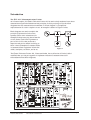
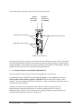
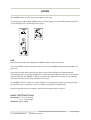
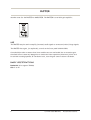
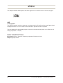
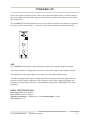
Emona 101
Telecommunications
Trainer
User Manual
Hands-on Experience in
Modern Analog & Digital
Telecommunications
Contents
Introduction.......................................................................................... i
ETT-101 System Conventions .......................................................... ii
1 - ADDERS.................................................................................................. 1
2 - BUFFER .................................................................................................. 2
3 – CHANNEL MODULE .......................................................................... 3
4 - DIVIDER................................................................................................ 4
5 – DUAL ANALOG SWITCH ................................................................ 5
6 - EXOR....................................................................................................... 6
7 – EXPANSION ........................................................................................ 7
8 – HEADPHONE AMPLIFIER............................................................... 8
9 – LINE CODE ENCODER...................................................................... 9
10 – MASTER SIGNALS ......................................................................... 11
11 - MULTIPLIER....................................................................................... 13
12 – NOISE GENERATOR....................................................................... 14
13 – PCM ENCODER................................................................................... 15
14 – PCM DECODER................................................................................... 18
15 – PHASE SHIFTER .............................................................................. 20
16 – SEQUENCE GENERATOR.............................................................. 22
17 – SERIAL TO PARALLEL ................................................................... 23
18 - SPEECH ................................................................................................ 24
19 – TUNEABLE LPF ................................................................................. 25
20 – TWIN PULSE GENERATOR ......................................................... 26
21 - UTILITIES......................................................................................... 27
22 – VARIABLE DC V ............................................................................... 28
23 - VCO ....................................................................................................... 29
ETT-101 System Specifications............................................................ 30
EC Declaration of Conformity................................................................ APP A
Introduction
The ETT-101 Telecommunications Trainer
As its name implies, the Emona Telecoms-Trainer 101 is used to help students learn about
communications and telecommunications principles. It lets you bring to life the block
diagrams that fill communications textbooks. A “block diagram” is a simplified
representation of a more complex circuit. An example is shown in Figure 1 below.
Block diagrams are used to explain the
principle of operation of electronic
systems (like a radio transmitter for
example) without worrying about how the
circuit works. Each block represents a
part of the circuit that performs a
separate task and is named according to
what it does. Examples of common blocks
in communications equipment include the
adder, multiplier, oscillator, and so on.
Figure 1
The Emona Telecoms-Trainer 101, illustrated below, has a collection of blocks (called
modules) that you can put together to implement dozens of communications and
telecommunications block diagrams.
© Emona Instruments
Introduction & Conventions
i
ETT-101 System Conventions
Making lab experiments interesting and informative is important when introducing new
technologies and concepts for the first time to students.
In order to help students use the ETT-101, so they spend their time learning about the
experiment rather than learning how to use the lab equipment, the front panel of the ETT101 has been laid out following a series of front panel conventions.
All ETT-101 modules conform to the following mechanical and electrical conventions.
A - FRONT PANEL SOCKETS
Signal interconnections are made via front panel, 2mm sockets.
Sockets on the LEFT HAND SIDE are for signal INPUTS.
All inputs are high impedance, either 10k ohms or 56k ohms depending on the module,
in order to reduce effects when connections are made and broken.
Sockets on the RIGHT HAND SIDE are for signal OUTPUTS.
All analog outputs are low impedance, typically 330 ohms. Again, this is to reduce
effects when connections are made and broken. Digital outputs are typically 47 ohms.
ROUND sockets, “
“, are only for ANALOG signals.
ANALOG signals are typically held near the ETT-101 standard reference level of
4V pk-pk.
SQUARE sockets, “
“, are only for DIGITAL signals.
DIGITAL level signals are TTL level, 0 to 5 V.
ROUND sockets labeled GND, “
“, are common, or system GROUND.
Note that input and output impedances are intentionally mismatched, so that signal
connections may be made or broken without changing signal amplitudes at module outputs.
Input and output sockets are protected from damage due mis-wiring.
B - LABELLING
All modules are identified as to the function they perform.
Inputs, outputs, controls and switches are labeled so that a student who has had only a
brief introduction to TIMS can use the modules without needlessly referring back to this
USER MANUAL.
© Emona Instruments
Introduction & Conventions
ii
Front panel input and output conventions are illustrated below:
INPUT
sockets on
the LEFT
OUTPUT
sockets on
the RIGHT
ANALOG input sockets
ANALOG output sockets
DIGITAL input sockets
EXAMPLE ETT-101 MODULE
It should be noted that variable controls do NOT have calibration marks. This is intentional,
as the philosophy behind TIMS is that students setup and adjust systems by observing and
measuring signals. This assists the student in gaining a much greater understanding, feel and
insight into the operation of a communications implementation.
C - PATCHING ERRORS and MAKING EXPERIMENTS
Input and output sockets are protected from damage due to mis-wiring.
An important part of the ETT-101 teaching philosophy is that students are free to
make mistakes while patching together experiments. By observing the result of their
mistake - when the signals do not look as expected - they can experiment and self-correct
to obtain the desired result.
Students are also free to experiment with different ideas by testing their own
understanding of how the mathematics or theories actually function in real life
implementations. The ETT-101 is ideally suited to helping students experience abstract
concepts and mathematics actually coming to life.
© Emona Instruments
Introduction & Conventions
iii
This page is intentionally blank.
© Emona Instruments
Introduction & Conventions
iv
ADDER
The ADDER module is used to sum two signals in real-time.
Two analog input signals A(t) and B(t) may be added together in adjustable proportions G and
g. The resulting sum is presented at the output.
USE
The ETT-101 provides two independent ADDER modules, as pictured above.
The first ADDER includes adjustable GAINS. The second ADDER module has fixed GAINS of
unity (x1).
Care must be taken when adjusting the gains to avoid overloading the following modules.
Overloading will not cause any damage but it means non-linear operation, which is to be avoided
in analog systems. The ADDER is capable of delivering a signal well in excess of the standard
reference level, 4V pk-pk, given a standard level input.
The ADDER can also be used as a normal amplifier by using only one input and turning the gain
of the other input to minimum. It is not necessary to ground the unused input.
Note that gains G and g are negative. All inputs and outputs are DC coupled.
BASIC SPECIFICATIONS
Gain Range 0 < G < 2 (inverting);
0 < g < 2 (inverting);
Bandwidth approx 1MHz
ETT-101 USER MANUAL
© Emona Instruments
1
BUFFER
Another name for the BUFFER is AMPLIFIER. The BUFFER is a variable gain amplifier.
USE
The BUFFER may be used to amplify (increase) small signals or attenuate (reduce) large signals.
The BUFFER has a gain, (or amplitude), control on the front panel labeled GAIN.
Care should be taken to ensure that later modules are not overloaded due to excessive gain.
Overload will not cause any damage but it means non-linear operation (distortion), which is to
be avoided in analog systems. If overload occurs, turn the gain control counter clockwise.
BASIC SPECIFICATIONS
Bandwidth DC to approx 700kHz
Gain 0 to 10
2
ETT-101 USER MANUAL
© Emona Instruments
SPEECH
The SPEECH module allows speech and audio signals to be converted into an electrical signal.
USE
LIVE CHANNEL
The SPEECH module includes a sensitive microphone which will easily pick-up normal speech and
background noise. You do not need to lean towards or speak into the microphone.
The microphone will continuously output an electrical of about 2Vrms (that is, an effective AC
voltage equivalent to 2V DC).
BASIC SPECIFICATIONS
Microphone electret-type with frequency response of 300Hz to 3kHz
Output typically 2Vrms
24
ETT-101 USER MANUAL
© Emona Instruments
TUNEABLE LPF
Filters are important building block in electronics and telecommunications. A filter is used to
pass some signals and block other signals. A low pass filter passes low frequencies and blocks
high frequencies.
The TUNEABLE LPF module allows the user to vary which frequencies are passed by adjusting
the front panel fc control knob. fc is known as the cutoff frequency of the lowpass filter.
USE
The TUNEABLE LPF module accepts analog-level signals and outputs analog-level signals.
The cutoff frequency is adjustable by the user. The cutoff range is from 300Hz to 16kHz.
The amplitude of the output signal can be control via front panel GAIN control.
A digital-level squarewave signal is output which has a frequency 100 times higher than the
selected cutoff frequency. Measuring the frequency of the digital signal and dividing the
frequency by 100 will give the user an instantaneous reading of the TUNEABLE LPF cutoff
frequency.
BASIC SPECIFICATIONS
Filter Range 600 Hz to 12 kHz
Filter Order 8th order, Elliptic
Stopband Attenuation > -50dB at 1.4 fc and Passband Ripple < 0.5dB
Gain Control 0 to x2
ETT-101 USER MANUAL
© Emona Instruments
25
ETT-101 System Specifications
STANDARD ACCESSORIES
Patch Cords 20 x 2mm-2mm stackable patch cords
Scope leads 3 x 2mm-to-BNC coaxial oscilloscope leads
Headphones 1 x lightweight stereo headphones, 24ohm, 3.5mm male stereo plug
Plug Pack multi-input voltage with 12V/1A output, regulated. Tip is positive
Documentation 1 x User Manual; 1 x Experiment Manual
POWER SUPPLY
Power Source multi-voltage plug pack supplied as standard
Power Supply 9V to 15V DC, 1A maximum
Protection reverse polarity and self resetting circuit breaker protection above 16V input.
Absolute Maximum Supply Input 30V DC
ENVIRONMENTAL
Operating Temperature Range 10 to 30 degrees C
Storage Temperature Range 5 to 40 degrees C
Humidity up to 90% RH, non-condensing
PHYSICAL
Case Dimensions front panel 280 x 232mm; height 32 to 70mm
30
ETT-101 USER MANUAL
© Emona Instruments
Emona-101 Telecommunications Trainer User Manual Experiments in Modern Analog and Digital Telecommunications.
Emona Instruments Pty Ltd
86 Parramatta Road
Camperdown NSW 2050
AUSTRALIA
web: www.ett101.com
telephone: +61-2-9519-3933
fax: +61-2-9550-1378
The "BISKIT" logo is a trademark of Emona TIMS PTY LTD