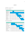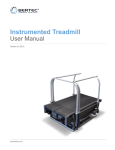
1
AUTONOMOUS QUADRUPED ROBOT
SIONG TECK YONG
UNIVERSITI TEKNOLOGI MALAYSIA
PSZ 19:16 (Pind. 1/07)
UNIVERSITI TEKNOLOGI MALAYSIA
DECLARATION OF THESIS / UNDERGRADUATE PROJECT PAPER AND COPYRIGHT
Author’s full name :
SIONG TECK YONG
Date of birth
:
26 SEPTEMBER 1986
Title
:
AUTONOMOUS QUADRUPED ROBOT
Academic Session:
2008/2009
I declare that this thesis is classified as :
CONFIDENTIAL
(Contains confidential information under the Official Secret
Act 1972)*
RESTRICTED
(Contains restricted information as specified by the
organisation where research was done)*
OPEN ACCESS
I agree that my thesis to be published as online open access
(full text)
I acknowledged that Universiti Teknologi Malaysia reserves the right as follows :
1. The thesis is the property of Universiti Teknologi Malaysia.
2. The Library of Universiti Teknologi Malaysia has the right to make copies for the purpose
of research only.
3. The Library has the right to make copies of the thesis for academic exchange.
Certified by :
SIGNATURE
SIGNATURE OF SUPERVISOR
860926-52-6613
DR.SALINDA BT BUYAMIN
(NEW IC NO. /PASSPORT NO.)
Date : 14 MAY 2009
NOTES :
*
NAME OF SUPERVISOR
Date : 14 MAY 2009
If the thesis is CONFIDENTIAL or RESTRICTED, please attach with the letter from
the organisation with period and reasons for confidentiality or restriction.
“I hereby declare that I had read this thesis and in my opinion, this thesis is
sufficient in term of quality and scope for the purpose of awarding a degree
of Bachelor of Engineering (Electrical- Mechatronics)”.
Signature
: ______________________________________
Supervisor
: DR. SALINDA BT BUYAMIN
Date
: 14 MAY 2009
AUTONOMOUS QUADRUPED ROBOT
SIONG TECK YONG
A thesis submitted in partial fulfillment
of the requirements for the award of the degree of
Bachelor of Engineering (Electrical-Mechatronics)
Faculty of Electrical Engineering
Universiti Teknologi Malaysia
MAY 2009
ii
DECLARATION
“I declare that this thesis entitled “Autonomous Quadruped Robot”,
is the result of my own research except as cited in the references. The thesis
has not been accepted for any degree and is not concurrently submitted in
candidature of any other degree.”
Signature
: ______________
Name of Candidate
: SIONG TECK YONG
Date
: 14 MAY 2009
iii
DEDICATION
Specially to my beloved
parents, siblings and friends
for their eternal support, encouragement
and inspiration throughout
my journey of education.
iv
ACKNOWLEDGEMENT
A journey is easier when you travel together. Interdependence is certainly
more valuable than independence. This project is the result of four months of work
whereby I have been accompanied and supported by many people. It is a pleasant
aspect that I have now the opportunity to express my gratitude for all of them. First
of all, I would like to express my deepest gratitude to my project supervisor, Dr.
Salinda Bt Buyamin, who had presently giving me guidance and support throughout
the entire project. It would be difficult to complete this project without her guidance
and support especially in the project resources, references and material.
Second, my outmost thanks to my family for their unconditional love and
support, especially over the duration of my degree. They have always stood by me
and have been willing to help in any way they can. I thank them for always believing
in me and for helping me to keep my spirits high.
Last but not least, sincere appreciation is conveyed to my friends, especially
to all my course mates who had given me help technically and mentally during the
journey to accomplish this project. Thank you all for giving me technical advice,
moral support and idea to enhance my project. Thank you.
v
ABSTRACT
Autonomous quadruped robot and artificial intelligence era had coloured the
robotic field nowadays. Many research had been conducted by researcher in
university and multinational companies, and even the military, to understand the high
mobility and stably autonomous robot on rough terrain. The success and admiralties
of the BigDog dynamically stable quadruped robot by Boston Dynamic and many
other legged robots available either in commercial market or researches had inspired
me to perform my final year project in the design and constructing of an autonomous
quadruped robot. This project involved the study and constructing of quadruped
robot mechanism, electronic, program and its interfacing with surrounding. This aim
of this project is to design a quadruped robot that perform automated legged robot,
construct a quadruped robot that performs optimization of gait patterns on a legged
robot and build a quadruped robot that is able to overcoming obstacles.
To capitalize on the efficiency and simplicity of wheeled robots, as well as
the adaptability and maneuverability of legged robots, many hybrid leg-wheel
designs have been developed. To date, none of these platforms have possessed the
ability to execute dynamic maneuvers and thus have major shortcomings in their
speed, efficiency and obstacle negotiating capabilities. Thus, a hybrid leg-wheel
quadruped capable of such dynamic behavior is introduced. This project proposes a
legged-wheel quadruped robot that can move flexibly with 14 servos for each joints
control.
vi
ABSTRAK
Robot automasi berkaki empat dan era kepintaran buatan telah mewarnai
bidang robotik masa kini. Banyak kajian telah dijalankan oleh universiti terkemuka
dunia dan industri termasuk tentera pertahanan untuk memahami kelancaran
perjalanan robot dan kestabilan automasi robot dalam keadaan jalan yang tidak rata.
Kejayaan dan kekaguman terhadap kehebatan robot BigDog
keluaran Boston
Dynamic dan robot berkaki lain yang terdapat di pasaran atau masih di peringkat
kajian telah memberi inspirasi kepada projek ijazah sarjana muda saya untuk
merekabentuk dan membina robot automasi berkaki empat. Projek ini merangkumi
kajian
dan
penghasilan
mekanisma
robot
empat-kaki,
system
elektronik,
pengatucaraan dan tindak balasnya dengan persekitaran. Matlamat projek ini adalah
untuk mereka robot berkaki empat yang berautomasi menjalani tugas dengan sendiri,
membina robot berkaki empat yang dapat mempamerkan bentuk perjalanan yang
berbeza, dan membina robot berkaki empat yang berupaya bertindak balas dengan
halangan hadapan.
Untuk memaksimumkan keberkesanan dan kefleksibelan pada robot beroda,
di samping daya penyesuaian dan pergerakkan pada robot berkaki empat, banyak
robot berkaki-roda telah direkabentuk. Pada masa kini, tiada satu platform yang
berkebolehan laksanakan daya penyesuian dan pergerakkan, terutamanya kekurangan
pada kelajuan, keberkesanan dan keupayaan bertindak balas dengan halangan.. Jadi,
robot berkaki-roda yang berkeupayaan seperti sifat di atas telah diperkenalkan.
Projek ini merangkumi robot berkaki-roda yang dapat bergerak dengan fleksibel
dengan 14 motor pada setiap sendi kawalan.
vii
TABLE OF CONTENT
CHAPTER
1
2
3
TITLE
PAGE
DECLARATION
ii
DEDICATION
iii
ACKNOWLEDGEMENT
iv
ABSTRACT
v
ABSTRAK
vi
TABLE OF CONTENTS
vii
LIST OF TABLES
xi
LIST OF FIGURES
x
LIST OF SYMBOLS AND ABBREVIATIONS
xiii
LIST OF APPENDICES
xiv
INTRODUCTION
1
1.0 Project Background And Inspiration
1
1.1 Hybrid Legged-Wheel Platforms
3
1.2 Problem Statement
5
1.3 Project Scope And Objectives
6
LITERATURE REVIEW
7
2.0 Preview
7
2.1 Dynamically Stable Quadruped Platforms
8
2.2 Hybrid Leg-Wheel Quadruped Robot
11
PROJECT OVERVIEW
15
3.0 Introduction
15
3.1 Concept
16
viii
4
5
3.2 Theory
18
METHODOLOGY
21
4.0 General Resources
21
4.1 Preview of Structure And Mechanism
22
4.2 Preview of Electronics System And Devices
24
4.2.1 Microcontroller PIC18F4550
25
4.2.2 Actuator
26
4.2.3 Power Supply
29
4.2.4 Analog Distance Sensor
30
4.3 Preview of Interfacing And Programming
31
4.4 Hardware And Mechanism Design
33
4.5 Electronic And Peripherals Interfacing
35
4.6 Programming
40
EXPERIMENT AND RESULT
44
5.0 Communication of AX-12 and PIC18F4550
44
Microcontroller
6
5.1 Program Debugging
45
5.2 Mode Selection
47
5.3 Quadruped Robot Formation
48
DISCUSSION AND CONCLUSION
51
6.0 Discussion
51
6.1 Suggestions And Future Development
52
6.2 Conclusion
53
REFERENCES
55
APPENDICES
Appendix A
Gantt Chart
57
ix
LIST OF TABLES
TABLE NO.
TITLE
PAGE
4.0
Characteristic Of AX-12+
27
4.1
Characteristic Of Analog Distance Sensor
31
4.2
Control Table Of Dynamixel
43
5.0
Quadruped Robot Mode Selection and Its
47
Function for Each Mode Selected
x
LIST OF FIGURES
FIGURE NO.
1.0
TITLE
Planetary explorer (left), Polar Rover Chassis (center)
PAGE
3
and Mars Pathfinder (right)
1.1
Hirose’s Roller-Walker (1996)
4
1.2
Hybrid locomotion of Leg-Wheel ASTERISK H
5
2.0
Raibert’s biped robot (1982)
8
2.1
Raibert’s quadruped robot (1985)
9
2.2
Patrush I (1994)
9
2.3
Patrush I with running legs (1997)
10
2.4
Patrush II (2000)
10
2.5
Tekken (2000)
11
2.6
The PAW
12
2.7
Labelled PAW components. Scout II component layout
12
is identical save for the lack of wheels and wheel
actuators
2.8
ATHLETE Rover with Brian Wilcox
13
2.9
AZIMUT on an incline surface
13
2.10
AZIMUT going through a door
14
3.0
The concepts to be implemented in the quadruped robot
17
project
3.1
Robot top views
18
3.2
Foot placement curve
19
3.3
Walk forward
19
3.4
Rotation to the right
19
3.5
Depiction of a trot gait
20
4.0
Methodology of quadruped robot design and
22
xi
construction flowchart
4.1
Quadruped robot basic structures
22
4.2
Robot’s leg design
23
4.3
Robot structure design
23
4.4
Quadruped robot structures.
24
4.5
The PIC 18F4550 characteristic specifications
25
4.6
Microchip 48MHz PIC 18F with USB block diagram
26
4.7
The AX-12+ smart servos
26
4.8
Input and output port in AX-12+
28
4.9
The wiring of AX-12+ servos from one AX-12+ to
28
another
4.10
NiMH 8 cell pack
29
4.11
Apache 2030 charger
29
4.12
Analog Distance Sensor
30
4.13
The general preview of the electronic interfacing part
31
of quadruped robot
4.14
The quadruped robot PIC 18F4550 microcontroller and
32
pins configuration for its peripherals interfacing
4.15
OF-12SH installations
33
4.16
Leg design and its dimensions
33
4.17
Quadruped robot structure and dimensions
34
4.18
Quadruped robot with legged mode (left) and wheel
34
mode (right)
4.19
Block diagram of quadruped robot electronic system
35
4.20
The main PIC microcontroller schematic
36
4.21
LED and push button interface circuit schematic
36
4.22
The oscillator and voltage regulator interface circuit
37
schematic
4.23
The circuit diagram to convert main controller UART
37
signals to the half duplex type
4.24
Half Duplex UART recommended circuit
37
4.25
Multi drop link
38
4.26
Quadruped robot electronic and peripheral interfacing
39
xii
layout
4.27
Quadruped robot program flow chart
40
4.28
Communication of main controller and Dynamixel
41
4.29
Connection of Dynamixel and main controller
41
4.30
Specific ID for each Dynamixel AX-12
42
4.31
Goal position of Dynamixel
42
5.0
USB ICSP PIC Programmers
45
5.1
The MPLAB IDE programming platform
46
5.2
PICkit 2 Programmer Applications
46
5.3
Main switch and manual mode selection on robot
47
5.4
Legged mode
48
5.5
Wheel mode
49
5.6
Series formation of robot encounters an obstacle
50
xiii
LIST OF SYMBOLS AND ABBREVIATIONS
A/D
-
Analogue to Digital
ADC
-
Analogue to Digital Converter
mm
-
millimeter
DC
-
Direct Current
IO
-
Input Output
IR
-
Infrared
ISR
-
Interrupt Service Routine
ms
-
Milliseconds
PWM
-
Pulse Width Modulation
TMR
-
Timer
xiv
LIST OF APPENDICES
APPENDIX
A
TITLE
Gantt Chart Semester 1 and 2
PAGE
57
1
CHAPTER 1
INTRODUCTION
1.0
Project Background And Inspiration
The ultimate goal of the field of robotics is to develop machines capable of
duplicating, or even surpassing, humans’ interaction with their environment. Such
machines have a wide range of application ranging from eliminating the human
element in menial tasks to removing humans from dangerous workplaces. Under the
umbrella of this broad discipline is the field of mobile robotics, which concentrates
on developing highly autonomous platforms that embody high mobility in even the
most unstructured environments. Towards this end, an exhaustive number of
wheeled and tracked robots have been developed. These platforms are favorable
attempts owing to their simplicity, power efficiency and most of all, their inherent
static stability. However, even after many years of maturity, these machines still fall
short of the mobility of humans or animals.
The relatively young field of legged robotics is working to exploit the
maneuverability and dexterity of legs to traverse highly unstructured terrain.
Although still in its infancy, the research in this discipline has had sufficient success
to demonstrate the substantial increases in mobility gained through the
implementation of legs. Imitating the superior terrain negotiating capabilities of
animals has not yet been realized, but the field is steadily progressing towards this
goal as the many researchers focus on various subsets of the enormous array of
hurdles.
2
There are many quadruped animals that have ideal mobility traits, thus a large
number of quadruped robots have been built in an effort to emulate nature’s proven
techniques. An attractive aspect of such a platform is that they can achieve static
stability by planting at least three of their legs on the ground and maintaining their
center of mass over this three leg tripod. With such a gait, the robot may stop and
hold its position at any instant of its execution without losing stability. These robots
are inherently slow and have poor power efficiencies not only from the requirement
of static stability, but also owing largely to the many degrees of freedom in their
legs. Their legs’ complexity, coupled with the large mass of many actuators, limit
the robot’s behavior and lend the robots to frequent breakdowns.
To realize faster speeds, increase efficiency and to widen the scope of
negotiable obstacles, legged robots capable of dynamic motion were developed.
Dynamically stable platforms are designed to maintain stability even when the
center of mass is outside the area of support formed by the legs contacting the
ground. Although the motion or gait is stable as a whole, each of the phases that
constitute the cyclic motion may be unstable. As such, these robots are not able to
simply stop and hold their position during the execution of a dynamic gait without
losing stability, making their control much more difficult. However, these gaits
often contain flight phases, which enable faster speeds and the ability to jump or
leap. Thus, a smaller robot with dynamic capabilities can use its kinetic energy to
increase its effective size and outperform a larger platform. Generally speaking,
dynamic robots mimic animal behavior more closely and have increased mobility
due to less restrictive movements. However, these behaviors usually require the
expenditure of large amounts of energy, making them difficult to implement on an
untethered, autonomously powered platform.
To capitalize on the efficiency and simplicity of wheeled robots, as well as
the adaptability and maneuverability of legged robots, many hybrid leg-wheel
designs have been developed. However, these platforms have been rather bulky,
complex machines that traverse terrain quite slowly. To date, none of them have
been able to venture into the dynamic realm and thus have major shortcomings in
their speed, efficiency and obstacle negotiating capabilities. The focus of this
3
project was to develop a means for hybrid leg-wheel platforms to realize dynamic
maneuvers. The work also had a more generalized target of expanding the currently
narrow scope of feasible dynamic behavior for autonomously powered platforms.
From both a mechanical and control stand-point, it was aimed to develop a simple
and robust robot. With high reliability and power autonomy, it will allow the
platform to be easily adopted for real world operation.
1.1
Hybrid Leg-Wheel Platforms
High cross-country ability and maneuverability are the major requirements
for mobile robots intended for operation on natural terrain. Many wheeled and
tracked platforms have been developed in an attempt to satisfy these requirements,
but a few decades ago many researchers began investigating alternative means of
locomotion to obtain higher mobility. Researchers realized that while legged
platforms have good terrain negotiating capability, wheeled locomotion was more
efficient at higher speeds. By combining legged and wheeled locomotion, they aimed
to gain effective natural terrain mobility with a large velocity range. These hybrid
machines have the potential of improved stability over rugged terrain, since the
wheels can maintain contact with the ground for a large percentage of the time.
Figure 1.0 Planetary explorer (left), Polar Rover Chassis (center) and Mars
Pathfinder (right).
Many leg-wheel platforms have been developed within the framework of
arctic and planetary exploration (i.e. Earth, Mars). Figure 1.0 left shows a sixwheeled experimental mock-up with a 320 kg rigid frame, utilizing a Chebyshev
mechanism. It is able to move in wheel-walking modes with continuous or
discontinuous walking (wheel mode - 0.9 km/hr, walking mode - 0.15 km/hr). Since
4
1995, the polar rover chassis (Figure 1.0 center) has been a widely adopted platform
for artic exploration [1] . The Mars Pathfinder, shown in Figure 1.0 right, is probably
the most widely recognized hybrid platform as its operation on Mars was
broadcasted internationally over many days [2]. Most of the planetary rovers use
novel kinematic mechanisms to passively adapt to the terrain and are still quite far
from merging true legged locomotion into the platforms.
Figure 1.1 Hirose’s Roller-Walker (1996).
Developed by Hirose at the Tokyo Institute of Technology (1996 to present),
the Roller-Walker (Figure 1.1) achieves wheeled locomotion by roller skating with
passive wheels [3]. Hirose fitted the TITAN VIII robot with special foot mechanisms
that rotate 90 degrees to change from a sole for walking to a passive wheel for
skating. Two legs powered the skating while braking was achieved by changing the
tangential angle of the wheels. The entire robot weighed approximately 24 kg. and
reached a speed of 0.8 m/s in skating mode – doubling TITAN VIII’s walking speed.
Although it was successfully implemented, it had low energy efficiency due to the
cyclic thrusting required to skate.
5
Figure 1.2 Hybrid locomotion of Leg-Wheel ASTERISK H.
The ASTERISK H [4] hexapod leg-wheel robot (Figure 1.2) traverses terrain
with steps where stable movement is possible by walking but not wheels by
alternating rolling and walking based on sensor feedback. When steps are small
enough for it to roll, it uses its wheels in basic positioning where 3 of 6 legs provide
support and the remaining 3 legs swing. When sensors on support legs detect an
obstacle too large to traverse on wheels, the robot attempts to walk over the obstacle
by switching support and swinging legs. The maximum obstacle height it manages
depends on the robot’s height and leg positioning.
1.2 Problem Statement
At present, there are many studies about leg-wheel hybrid mobile robot
because walking robot has high terrain adaptability on irregular ground but wheeled
robot takes advantage of moving speed on smooth terrain. In the past, active wheels
were often used for wheeled locomotion. However installation of active wheels
restricted walking machine's ability very much because active wheels need actuators,
brake mechanism and steering mechanism. This equipment is so heavy and bulky
that it's not practical solution for walking robot which has many degrees of freedom.
As mobile robots are required to operate in increasingly challenging environments,
the limitations of traditional wheeled and tracked vehicle designs become increasingly
apparent: their simple and robust design does not provide sufficient versatility and
6
adaptability for many real-world terrain conditions. Design modifications, which add passive
or active degrees of freedom with or without compliance, can be made to make these
vehicles better suited to rough terrain. The constraints and challenges that been discuss
had bring an inspiration and aspiration to me to design and construct an autonomous
hybrid leg-wheel quadruped robot.
1.3 Project Scope And Objectives
The project of design and construct an autonomous hybrid leg-wheel robot will
mainly focus on its capabilities to perform optimization of gait patterns on a legged mode
and the implementation of wheel mode on flat surface. A wide research, references and
bench marking with previous and interrelated project will also be gone through to study their
achievement, constrains, ideas and fulfill the aims to build a stable, organic and robust
quadruped robot.
Basically the quadruped robot project is to design and build a hybrid leg-wheel
robot that can changes between feet soles for the walking mode and wheels for the wheel
mode. The robot will be attached with interactive sense. The main interactive sense is the
ability of the robot to interact with object and obstacle. A variety modes of movement
such as walking and turning with legged mode, implementation of wheel mode on flat
surface, pass forward obstacles, climbing up the obstacles, obstacle avoidance and high
speed walking mode. All those modes are activated autonomously by a looping program
with mode selection.
On the wider scope of accomplishment, the quadruped robot project is hoped to
play a role in the mobile robots that intended for operation on natural terrain and for
further enhancement and research on the hybrid leg-wheel robot in robotic field.
7
CHAPTER 2
LITERATURE REVIEW
2.0
Preview
Many form of mobility have been proposed for designing the quadruped
robot. These resources can be obtained via the access to the internet, the faculty
thesis center and references on electronic journal and research paper. In this chapter
the discussion will be focus on the quadruped robot which is relevant to the project
title. Meanwhile technical references mainly will be focus on the design of
mechanism, electronic parts and finally the most difficult part of hardware and
software interfacing.
Mostly the online references nowadays are not only focus on web based
protocol but references from interactive video sharing website, mostly from
www.youtube.com and online discussion and sharing portal make it possible for
better resources gathering. Online search by image browsing is another effective and
fast method to obtain references for the quadruped robot project.
Meanwhile, the possible accesses to the references of previous year student
project and research either from the local internal university resources or external
sources are also encouraging for having more detail and reliable literature review and
references.
8
The literature review documentation for the quadruped robot project will be
divided into few part, mainly first focusing on the study of quadruped locomotion on
structure and mechanism, secondly the study on the relevant projects and the references
on the technology and technical part.
2.1
Dynamically Stable Quadruped Platforms
Many research conducted by worldwide higher learning institute to study the
dynamically stable quadruped platform, gait and locomotion behavior and their
reaction with human and surrounding had accomplish a lot of knowledge and
contribution to the robotic field.
Figure 2.0 Raibert’s biped robot (1982).
Raibert pioneered the field of dynamically stable legged robots with the
introduction of a series of hopping robots [5]. In 1982, MIT’s Leg Laboratory,
founded by Raibert, developed a planar one-legged hopping robot that travelled at
speeds up to 1.2 m/s, tolerated moderate disturbances and jumped over small
obstacles. The platform, see Figure 2.0, was able to perform such seemingly complex
dynamic feats through the use of rather simple controllers compared to those
typically adopted at the time. The control was simplified mainly by separating the
task of forward propulsion from that of the vertical hopping. The hopping height was
maintained and adjusted by the pneumatic piston that serves as the leg, while the
horizontal speed was adjusted using two pneumatic actuators that pivot the leg about
9
the hip. By simply varying the touchdown position of the toe with respect to the
center of mass of the robot, the speed and trajectory of the robot were adjusted.
Figure 2.1 Raibert’s quadruped robot (1985).
Raibert applied the same control laws to implement a 3-D hopper in 1983 and
subsequently developed multiple legged robots using the same principles. He
developed bipeds by treating each of the legs as a single hopping leg, cyclically
designating an active leg and an idle leg. Then, by pairing the legs of a quadruped,
Raibert managed to reduce its control to an equivalent virtual biped – thereby
controlling a four legged platform with the same approach as the one legged hoppers.
Pictured in Figure 2.1 is the Leg Lab’s dynamic quadruped that was developed
between 1984 and 1987. The platform is hydraulically actuated with three DOF legs:
one at the hip in the pitching plane; a second at the hip in the yaw plane; and the third
in the prismatic leg, which is actuated by a hydraulic cylinder in series with a passive
pneumatic spring. By coupling the legs, the quadruped successfully executed trotting
(diagonally paired legs), pacing (lateral pairs), bounding (front pair and rear pair) and
several transitions between gaits.
Figure 2.2 Patrush I (1994).
10
In 1994, Kimura et al. introduced a planar quadruped called Patrush [6] that
used a biologically inspired approach for its control. Shown in Figure 2.2, each leg of
Patrush I had three joints about the pitch axis; the two upper joints were actuated
with DC motors and the lower joint was passively compliant. The 4.6 Kg robot had a
body length of 360 mm, a height of 330 mm and a width of 240 mm. It successfully
executed trot and pace gaits, and by 1996, the platform was able to negotiate
irregular terrain consisting of slopes (up to 12°) and small steps (up to 30 mm).
Patrush I was fitted with special running legs in 1997, see Figure 2.3 that enabled the
robot to hop and bound along a flat surface. These legs had the same basic
configuration as the original legs, but had a much larger ankle. Presently, a second
variation of the platform, Patrush II (Figure 2.4), is being used by Kimura’s lab as a
means to compare and study the differences between simulation and experiment.
Figure 2.3 Patrush I with running legs (1997).
Figure 2.4 Patrush II (2000).
To test the biological control approach in three dimensions, Kimura’s
laboratory built a new quadruped, Tekken, in 2000 [7]. Pictured in Figure 2.5, the
11
platform has four DOF legs: two DOF at the hip (pitch and yaw), one DOF at the
knee (pitch) and a passively compliant ankle (pitch). The 3.1 Kg robot had a body
length of 400 mm, a height of 210 mm and a width of 120 mm. Tekken has
performed dynamic walking gaits over flat surfaces (up to 1m/s) and over irregular
terrain that consisted of slopes (up to 10°) and small steps (up to 40 mm). It has
also executed running or bounding gaits over flat terrain, but the majority of the
current research on this platform is directed towards improving Tekken’s mobility on
irregular surfaces.
Figure 2.5 Tekken (2000).
2.2
Hybrid Leg-Wheel Quadruped Robot
Although there are a lot of references available online and in video format from
www.youtube.com, three (3) relevant and main references had been selected as
references and bench marks for the quadruped robot project.
The first literature review is from the research conducted by Department of
Mechanical Engineering, McGill University Montreal, Canada. The project title, PAW
[8] (Platform for Ambulating Wheels) robot, as picture in Figure 2.6, which it shares a
T-shaped body (albeit lighter and more compact) and compliant legs.
12
Figure 2.6 The PAW.
PAW also bears resemblance to articulated suspension systems, combining
aspects of legged and wheeled locomotion in order to achieve greater mobility.
PAW’s legs are equipped with actuated hard rubber wheels instead of fixed toes. In
wheeled modes of operation the four hip motors can reposition the wheels with
respect to the body of the robot. Many of PAW’s wheeled behaviors are primarily
kinematic, but they have implications for high-speed locomotion in which vehicle
dynamics play a role, such as in braking and high-speed turning. In legged modes,
the wheels may be actively controlled, allowing dynamic behaviors such as jumping
and bounding.
Figure 2.7 Labelled PAW components. Scout II component layout is identical save for the
lack of wheels and wheel actuators.
The second reference on quadruped robot is The Athlete Rover [9] developed by
a team that includes NASA's Johnson and Ames Centers, Stanford University, and
Boeing. Athlete (All-Terrain Hex-Legged Extra-Terrestrial Explorer) robot vehicle is
capable of rolling over Apollo-like undulating terrain and "walking" over extremely
rough or steep terrain so that robotic or human missions on the surface of the Moon
can load, transport, manipulate, and deposit payloads to essentially any desired sites
of interest.
13
Figure 2.8 ATHLETE Rover with Brian Wilcox.
The Athlete is able to move at 10 km/h over Apollo-like terrain (>100 times
faster than Mars Exploration Rover (MER)), climb vertical steps of at least 70% of
the maximum stowed dimension of the vehicle (>2x MER), climb slopes of 35° on
rock and 25° on soft sand, load, transport, manipulate, and deposit mock payloads in
a useful fashion and be stowed and docked compactly for launch into an annular ring
so that many vehicles can be efficiently stacked around a main payload on a single
lander. The system is an Earth test-bed vehicle, controlled via an immersive user
interface similar to that used for the MER mission. However, unlike the Mars usage,
simulated Earth-Moon time delay will be used for operations.
By the end of this project, NASA will be able to confidently conduct an
affordable lunar-surface flight experiment that demonstrates this technology on the
Moon and subsequently uses it as part of the Human Lunar Return campaign to
perform the needed robotic/human vehicle functions on the lunar surface.
Figure 2.9 AZIMUT on an incline surface.
14
The third quadruped robot project reference is named AZIMUT [10], modular
mobile robotic platform with legs-tracks-wheels. AZIMUT addresses the challenge
of making multiple mechanisms available for locomotion on the same robotic
platform. AZIMUT has four independent articulations that can be wheels, legs or
tracks, or a combination of these. By changing the direction of its articulations,
AZIMUT is also capable of moving sideways without changing its orientation,
making it omnidirectional. All these capabilities provide the robot with the ability to
move in tight areas.
AZIMUT is designed to be highly modular, placing for instance the actuators
in the articulations so that the wheels can be easily replaced by leg-track articulations
for all-terrain operations. Stability and compliance of the platform are enhanced by
adding a vertical suspension and using elastic actuators for the motorized direction of
AZIMUT’s articulations. An elastic element is placed in the actuation mechanism
and a sensor is used to measure its deformation, allowing to sense and control the
torque at the actuator’s end. This should improve robot motion over uneven terrains,
making the robot capable of ``feeling'' the surface on which it operates. Mechatronic
modules, such as the wheel-motor that is used in the wheel and the leg-track
configurations, and the use of a distributed processing architecture with multiple
microcontrollers communicating through shared data buses. AZIMUT's design
provides a rich framework to create a great variety of robots for indoor and outdoor
uses, and makes it one of the most advanced wheeled robotic platforms available.
Figure 2.10 AZIMUT going through a door.
15
CHAPTER 3
PROJECT OVERVIEW
3.0
Introduction
Basically, Autonomous Quadruped Robot consists of 2 main mode which are
legged mode and wheel mode that can perform different task. It is a hybrid leggedwheel robot that can move flexibly with 14 servo motors for the joint control (3
Degree of Freedom per leg).
The Autonomous Quadruped Robot consists of the following feature:
-
Autonomous robot which can perform desired task without continuous human
guidance.
-
Can move flexibly, with 12 servo motors for the joints control.
-
4 legs lifting vertically and turning horizontally.
-
Legged mode that can be transform into wheel mode, with additional 2 servo
motor attach onto leg.
-
Sensor for sensing the obstacles, react according to the situation, including
obstacles avoidance, pass forward obstacles, and climb over obstacles.
On the other hand, the quadruped robot project do faced some challenges and
constraints in both the technical part and project implementation.
On the technical part, initially the projects face the constraint of choosing the
best brain for the robot. At first the PIC18F452 microcontroller was chosen to be
implemented on the robot, PIC18F452 perform a fast, low power controller with a
16
quick UART communication speed. The operation of the enhanced USART module
is controlled through 3 register: Transmit Status and Control (TXSTA), Receive
Status and Control (RCSTA) and Baud Rate Control (BAUDCON). However, while
testing the Rx/Tx pin on output value, PIC18F452 kept burning out. Midway through
this PIC burning phase, I ran out of PIC18F452, and subsequently discovered new
flash Microchip PIC microcontrollers with certified Full-Speed USB 2.0 connectivity
and 48 megahertz (MHz) operation, PIC18F4550. For the task and robustness
demand of the quadruped robot project, the 18F PIC class microcontroller was able
to perform all the require task. The electronic circuit of the PIC interface circuit
constructed through dummy board. The challenging part will be how to drive the PIC
serial port in half duplex mode (tristate on receive, drive on TX) at the right speed.
On another part, the hardware and structure of the quadruped robot
mechanism which had been proposed on the early first semester had to be redesign in
order to increase the maneuverability and dexterity of legs to traverse highly
unstructured terrain.
3.1
Concept
Based on the introduction and literature review, it is fairly understand that the
quadruped robot project is one of the kinds to create a hybrid legged-wheel robot
based on the study and implementation of variety of dynamic behaviors. The
placement of wheels at the foot of the legs significantly widens the scope of feasible
dynamic behavior for a quadruped platform. Most notable is it allows the robot to
overcome obstacles greater in height than the platform itself. Thus in order to design
and produce a complete project which concern on the elements of technology,
dynamic behavior and dynamically stable quadruped platform, a lot of concepts and
inspiration either from the nature, science knowledge, art, and user psychology had
been concern in the preliminary stage of the project design and planning.
17
Basically, the concept that will be implemented in this project consists of the
concept of quadruped robot available in the market, the inspiration of robotic
technology, the dynamically stable gait motion knowledge, the technology of
microprocessor and mechanism design, and finally the bench mark from project
available.
Figure 3.0 The concepts to be implemented in the quadruped robot project.
Mean while, the inspiration from the success story of the Honda Humanoid
robot, ASIMO and other grand robotic product who had received world recognize
and admiration will be apply in this project as an inspiration and strength of moral
spirits.
The hardware design, mechanism structure and programming style will
basically adapt the dynamically stable and gait motion knowledge of the studies of
the legged robot and wheel robot characteristic. Meanwhile, the technology of
microcontroller, programming skills, hardware design and variety of interactive
senses will be implemented in the project in order to produce the best and successful
project. On the other hand, those success story and project from previous year project
within the faculty and those grand project published on the websites, will be
implemented as the bench mark for the quadruped robot project. A success project
18
needs focusing on the technology and project accomplishment, besides, the product
of the project are suitable for market or for further usage either in study, exhibition or
as a bench mark for other project.
3.2
Theory
A gait is a cyclic, periodic motion of the joints of a walking robot. For
quadrupeds, statically stable walking gaits have at least 3, and dynamically stable
gaits at least 2 legs, in contact with the ground at all times. The legs of the robot
cycle through the gait with a particular phasing. Presented is a method to choose the
phasing according to the direction of motion of the centre of mass of the robot.
A set of requirements were drawn up that the walking needed to satisfy [11] .
These included:
i. Omni-directional motion - The robot should be able to walk in all directions.
ii. The gait should move the robot as fast as possible. Since the robot would be
moving forward most of the time, it was decided that the robot should be
able to move forward at the maximum speed possible.
Figure 3.1 Robot top views.
Vx and Vy - are translation velocities
w - rotational velocity
c – Center of gravity
L – Step length
iii. Stability - It was important that the robot should remain stable at all times.
19
Figure 3.2 Foot placement curve.
Figure 3.3 Walk forward.
Statically stable ¾ duty cycle provides a stable gait for at least one type of
desired motion. Only in phase 4 a leg is not in contact with the ground trying to make
statically stable gait and concluded that each of the four legs should be in the
different phase. Leg has to follow the sequence of phases 1-2-3-4 (Figure 3.2).
Figure 3.4 Rotation to the right.
20
Figure 3.5 Depiction of a trot gait.
21
CHAPTER 4
METHODOLOGY
4.0
General Resources
Generally, before starting the design and planning stage for the quadruped
robot project, an intensive study and observation on the 4 legged robot, such as
Roller Walker, Tekken II, Scout and PAW robot had been carried out to get the
general idea and a preliminary back ground on the process or methodology which
had to carried out in order to complete the project. Those high end biological inspired
pet robots had been studied and observe their performance through online websites,
online video, E-journals and toys shops. This task is perform in order to study the
concepts, creativity and structural design of the quadruped robot, in the terms to
perform reverse engineering stage on those successful products.
The next stage which is more technical is the stage to collect relevant
resources for the project such as the data sheet for the microcontroller, sensor,
electronic components and servos. From those information obtain, the most suitable
devices is chose. Next for the hardware design, the mechanism structure is designed
based on kinematics and stability knowledge and technology. Finally all the elements
are combine and mount together to test run and complete the project.
22
Hardware Construction
Mechanism Testing
Hardware Modification
Circuit Troubleshooting
Circuit Development
Mechanism Retest
Circuit Testing
Circuit Modification
Circuit Interfacing
Program testing
Software Debugging
Software Development
Program Modification
Trail Run
Overall Modification
Documentation
Project Presentation
Project Complete
Figure 4.0 Methodology of quadruped robot design and construction flowchart.
4.1
Preview of Structure And Mechanism
1
2
3
4
Figure 4.1 Quadruped robot basic structures.
23
Autonomous Quadruped Robot consist of 14 servo motors, which leg 3 and
leg 4 consists of 3 servo per leg, leg 1 and leg 2 consist of 4 servo per leg. The
addition 1 servo at leg 1 and leg 2 is for wheel mode purpose. All 4 legs will be
attached to a wheel and there is a sensor in front of the robot to sense the obstacles.
Autonomous Quadruped Robot was designed using the aluminum plate,
acrylic, and plastic bracket. Adhesive skid protector are paste on each legged of robot
in order to increase the friction force between robot and the contact ground.
Figure 4.2 Robot’s leg design.
Figure 4.3 Robot structure design.
24
Figure 4.4 Quadruped robot structures.
4.2
Preview of Electronic System And Devices
On the circuit and electronics parts, the first stage of the design methodology
is to understand the requirements of the project and the limitation of various
constraints such as the level of technology, microcontroller reliability and the
complexity of programming and interfacing. First, an intensive studies is conducted
to learn and observe the others circuit and devices used by previous year projects and
research projects conducted worldwide. From those technical studies of the circuit,
schematic layout and components used, the suitable and most reliable circuits,
components and peripheral interfacing method are modified and applied to the
quadruped robot electronics stage.
The first stage is to choose the suitable microcontroller for the quadruped
robot project and the PIC18F4550 microcontroller had been selected due to its
reliable performance and availability to program in C-language. Below is the
characteristic specification show the advancement of the microchip.
25
4.2.1
Microcontroller PIC18F4550
Figure 4.5 The PIC 18F4550 characteristic specifications.
PIC18F4550 is a new Full-Speed USB PIC microcontroller family that can
perform as the sole controller in embedded applications thanks to the performance of
its powerful 12 MIPS RISC core, self-programmable Flash memory and the powersaving features of nanoWatt Technology.
One of the USB Microchip PIC microcontroller family’s key features is its 24
or 32 Kbytes of self-programmable Enhanced Flash memory, which allows field
upgrades for end applications via the USB port. Microchip’s advanced PMOS
Electrically Erasable Cell (PEEC) Flash technology provides high endurance of up to
100,000 erase/write cycles and long data retention of more than 40 years. In addition,
its Full-Speed USB 2.0 interface includes an onboard transceiver and a Parallel
26
Streaming Port for direct data transfers to external peripherals with minimum CPU
overhead.
Figure 4.6 Microchip 48MHz PIC 18F with USB block diagram.
After chosen the brain of the quadruped robot, the next step is to choose the
peripherals for the robot. The basic components will be servo motors as actuators,
analog distance sensors for obstacle and object detection, and LED in various
interactive formations of the robot.
4.2.2 Actuator
Figure 4.7 The AX-12+ smart servos.
27
AX-12 servo motors is selected for this project. It uses digital communication
to receive its commands unlike most servos. These servos are analog and require a
Pulse Width Modulation signal to determine the desired output, meaning a periodic
signal is constantly being sent to the servo whose duty cycle determines the position
the servo should go to. The AX-12 is a digital actuator so we need to tell it to do is to
go to a specific position and it will. Also, in general, digital communication is much
faster than analog communication.
Another feature that is only allowable due to the digital nature of the actuator
is the ability to daisy chains multiple actuators together. Daisy Chain is simply the
term allotted to the hardware setup where multiple devices are connected to each
other in series, where the first device connects to the source, in our instance the PIC
Microcontroller, the second device connects to the first, the third device to the
second, and etc. Aside from its obvious coding advantages, I also do not have to
worry about multiple wires hanging off our robot and going to the different pins of
our PIC. I only need 2 pins to control the movements of up to 255 actuators.
Weight (g)
Gear Reduction Ratio
Input Voltage (V)
Final Max Holding Torque (kgf.com)
Sec/60 degree
AX-12
55
1/254
At 7V
12
0.269
At 10V
16.5
0.196
Table 4.0 Characteristic of AX-12+.
The AX12+ servos have 2 male connectors on the back of each them. The left
port is the input port and the right port is the output port (see figure 2). The output
port connects to the next AX12+ servos input port. The AX12+ servos are connected
in sequential order when building the quadruped robot.
28
Figure 4.8 Input and output port in AX-12+.
Figure 4.9 The wiring of AX-12+ servos from one AX-12+ to another.
The AX-12 has a special protocol that it uses to communicate between the
PIC and the AX-12. The instruction packet looks like:
OXFF, 0XFF, ID, LENGTH, INSTRUCTION, PARAMETER1, …PARAMETER N,
CHECK SUM.
Two bytes of 0xFF are sent to indicate that we want to talk to the motors.
Then the ID byte is sent to specify which motor we want to talk with. If we want to
talk with all of them, we use the ID 0xFE. Next we send the length of the packet
being sent.
Length is determined by: Number of Parameters (N) + 2
The hex instruction is then written in (table of instructions are found in the AX-12
manual on page 19[12]). Parameters for each of the instructions are then written in
next. Finally a check sum is needed to make sure what we are writing in is correct.
29
Check sum is determined by: NOT(ID + Length + Instruction + Parameter1 + …
Parameter N) .
4.2.3 Power Supply
Figure 4.10 NiMH 8 cell pack.
The power supply part is the most critical unit in an electronic project. All the
microcontroller, analog distance sensors and servomotors require for 5V and 9.6V
respectively, and it is obtain from the power supply. Rechargeable NiMH 9.6V,
2700mAh, 8 cell pack batteries will be used to power quadruped robot. The NiMH
battery are quite small, light and has longer life spend and can be recharge to many
cycles.
Figure 4.11 Apache 2030 charger.
30
For the battery charger, the Apache 2030 smart charger has been selected
along with switching power adaptor 12V5A SMPS. For the Apache 2030 smart
charger have the following characteristic:
-
Compact, Reliable, Intelligent and Safer
-
Supports Li-Poly: 1 to 3 cells
-
Supports Ni-MH: 1 to 8 cells
-
Supports Ni-Cd: 1 to 8 cells
-
Automatic cell count select on Ni-MH and Ni-Cd
-
Manual cell count select on Li-Poly
-
Input voltage: 10.5V ~ 15V
-
Selectable output voltage: 4.2V (per cell)
-
Selectable charge rates: 110mA, 250mA, 500mA, 750mA, 1200mA
-
Reverse polarity & short circuit protection system
-
Automatic switches to "Trickle Mode" when charging complete
-
Dimensions: 90mm x 48 mm x 11mm / 3.546 x 1.8912 x 0.4334 in.
4.2.4 Analog Distance Sensor
Figure 4.12 Analog Distance Sensor.
Analog distance sensor is selected for sensing the obstacles.
Features:
- Less influence on the color of reflective objects, reflectivity
- Line-up of distance output/distance judgment type
Detecting distance: 10 to 80cm
Judgement distance: 24cm (adjustable within the range of 10 to 80cm)
31
-
External control circuit is unnecessary
Low cost
Parameter
Operating supply
voltage
Symbol
Vcc
Rating
4.5 to +5.5
Unit
V
Table 4.1 Characteristic of analog distance sensor.
Figure 4.13 The general preview of the electronic interfacing part of quadruped
robot.
4.3
Preview of Peripherals Interfacing And Programming
The PIC18F4550 series which may support C programming language will be
fully utilize to operate based on the C-language in the programming mode. The
microchip compiler software itself, MPLAB will be used as the programming
32
platform to write the program, simulate and compile to the hex file before be loader
into the microcontroller.
The program written in C language is set to perform a solely autonomous
quadruped robot that will be programmed to walk for legged mode, wheel mode and
interact with surrounding. The quadruped robot is autonomous in the sense that it
will respond to its surrounding and perform unstructured task based on the respond
signal on the front side of the robot and thus activated its modes selection
automatically. Via the analog distance sensor, the robot is able to perform a number
of modes such as obstacle avoidance, pass forward obstacles, and climb over the
obstacles.
PIC MPLAB microcontroller programming software will be use as the
platform to write the program, simulate, debug, verified and burn the hex file into the
microcontroller via ICSP programmer. In order to perform in-circuit debugger
programming during real time operation (RTO) fine-tuning of the robot, In-Circuit
Debugger ICD2 schematic had been added to the main circuit to support the incircuit debugger function.
Figure 4.14 The quadruped robot PIC 18F4550 microcontroller and pins
configuration for its peripherals interfacing
33
4.4
Hardware And Mechanism Design
The prototype of the quadruped robot chassis and the locomotion mechanism
of its quadruped leg had been designed and developed. The full design of the
prototype was develop by using aluminum plate and acrylic. For the leg design, the
OF-12SH (servo bracket) is installed on the AX-12 as shown in Figure 4.15.
Figure 4.15 OF-12SH installations.
Figure 4.16 Leg design and its dimensions.
34
The illustration below summarized the quadruped robot structure and
mechanism design.
Figure 4.17 Quadruped robot structure and dimensions.
The final structure of the robot consists of the specification of 43mm height,
250mm length, and 120mm width; with its full weight of 1.85kg. The robot consists of
main circuit of PIC circuit, analog distance sensor, LCD display and Ni-MH battery to
be fixing inside the main body.
Figure 4.18 Quadruped robot with legged mode (left) and wheel mode (right).
35
4.5
Electronic And Peripherals Interfacing
In order to program the PIC microcontroller, test the program and interface
all the hardware and electronics devices, the main interface circuit has to design. The
first stage is to try part by part of the circuit that is trying on proto board the voltage
regulator part, the PIC in-circuit debugger part, servomotor part, LCD Display
interface and analog distance sensor part.
Switches of push button for
microcontroller master clear reset and manual mode selection button for robot are
also tested. After that, all the sub circuits’ part is joint together to produce the
complete schematic.
Figure 4.19 Block diagram of quadruped robot electronic system.
36
Figure 4.20 The main PIC microcontroller schematic.
Figure 4.21 LED and push button interface circuit schematic.
37
Figure 4.22 The oscillator and voltage regulator interface circuit schematic.
Figure 4.23 The circuit diagram to convert main controller UART signals to the half
duplex type.
For the connection to UART, in order to control the Dynamixel actuators, the
main controller needs to convert its UART signals to the half duplex type. The
recommended circuit diagram for this is shown below (Figure 4.24).
Figure 4.24 Half Duplex UART recommended circuit.
The power is supplied to the Dynamixel actuator from the main controller
through Pin 1 and Pin 2 of the Molex3P connector. The direction of data signals on
38
the TTL level TxD and RxD depends on the DIRECTION_PORT level as the
following:
-
When the DIRECTION_PORT level is High: the signal TxD is output as
Data
-
When the DIRECTION_PORT level is Low: the signal Data is input as RxD
A multi-drop method of connecting multiple Dynamixel actuators to a single
node is possible by using the half duplex UART. Thus a protocol that does not allow
multiple transmissions at the same time should be maintained when controlling the
Dynamixel actuators.
Figure 4.25 Multi drop link.
39
Slide Switch
Push Button
LED
LCD Display
Analog
Distance Sensor
ISCP
Programmer
Ni-MH Battery
Microcontroller
Circuit
Figure 4.26 Quadruped robot electronic and peripheral interfacing layout.
40
4.6
Programming
START
Declare and load PIC18F active library
[p18f4550.h], timer [timer.h], delay
[delay.h]
Declare parameter of subfunction, push
button, servo motor instruction set, LED,
LCD Display
Declare value for Dynamixel position
and speed
Receive
activation signal?
No
Wait
Yes
Mode
Selection
Legged
Mode
Wheel
Mode
Obstacle
Encounter
Transform into
wheel robot
Walking
No
High-speed
Walking
Transform into
wheel robot
Walking
No
No
No
No
Obstacles?
Obstacles?
Obstacles?
Yes
Obstacles?
Yes
Yes
Yes
Move
backward &
turning left
Stop
Move
backward &
turning left
Able to
climb over?
Climb over
obstacles
END
No
Continuous
mode?
Yes
Figure 4.27 Quadruped robot program flow chart.
41
The microcontroller used in the quadruped robot project is the PIC 18F4550
series and it support C-language. The quadruped robot programming flow chart will be
shown on this part and will be converted into the C-language together with the
pic18f4550.h library using the student version of the C-18 PIC complier. The quadruped
robot program flow chart is shown on figure above (Figure 4.27). The full program is
attached on the appendix.
The main controller communicates with the Dynamixel units by sending and
receiving data packets. There are two types of packets; the “Instruction Packet” (sent
from the main controller to the Dynamixel actuators) and the “Status Packet” (sent
from the Dynamixel actuators to the main controller.)
Figure 4.28 Communication of main controller and Dynamixel.
For the system connection below, if the main controller sends an instruction
packet with the ID set to N, only the Dynamixel unit with this ID value will return its
respective status packet and perform the required instruction.
Figure 4.29 Connection of Dynamixel and main controller.
42
If multiple Dynamixel units have the same ID value, multiple packets sent
simultaneously collide, resulting in communication problems. Thus, it is imperative
that no Dynamixel units share the same ID in a network node.
ID=e
ID=6
ID=5
ID=4
ID=1 ID=2
ID=8
ID=7
ID=d
Dynamixel AX-12
actuator
Microcontroller
ID=9
ID=3
ID=a
ID=b
ID=c
Figure 4.30 Specific ID for each Dynamixel AX-12.
Figure 4.31 Goal position of Dynamixel.
The requested angular position for the Dynamixel actuator output to move to.
Setting this value to 0x3ff moves the output shaft to the position at 300° as shown in
the Figure 4.30. For the endless turn, both values for the CW Angle Limit and the
CCW Angle Limit are set to 0, and endless turn mode can be implemented by setting
the Goal Speed. This feature can be used for implementing a continuously rotating
wheel.
43
Address
Item
Access
Initial Value
3(0X03)
ID
RD,WR
1(0x01)
4(0X04)
Baud Rate
RD,WR
34(0x22)
6(0X06)
CW Angle Limit (L)
RD,WR
0(0x00)
7(0X07)
CW Angle Limit (H)
RD,WR
0(0x00)
8(0X08)
CCW Angle Limit (L)
RD,WR
255(0xFF)
9(0X09)
CCW Angle Limt (H)
RD,WR
3(0x03)
30(0X1E)
Goal Position (L)
RD,WR
[Addr36]Value
31(0X1F)
Goal Position (H)
RD,WR
[Addr37]Value
32(0X20)
Moving Speed (L)
RD,WR
0
33(0X21)
Moving Speed (H)
RD,WR
0
Table 4.2 Control table of Dynamixel.
44
CHAPTER 5
EXPERIMENT AND RESULT
5.0
Communication of AX-12 and PIC18F4550 Microcontroller
The following are the method to communicate the AX-12 with PIC18F4550
microcontroller. In the order to get the responses between AX-12 and
microcontroller, be sure that:
-
The PIC baud rate is as close to the actual one.
-
Not to accidentally write to baud register. Can only recover from this if I have
a utility to sweep the baud rate on microcontroller and ‘ping’ to find out what
the unintentional value was.
Likely mistake:
-
Checksum not calculated properly.
-
Half-duplex circuit not designed properly.
-
Half-duplex circuit is proper, but software did not switch in/out at the correct
moment.
From the recommended circuit in the manual, direction can only be switched
after the checksum byte has been completely sent. A common mistake would be to
switch the direction to input immediately after writing the checksum value to the
TxREG. The correct way to switch is:
-
Switch to output.
-
Write header and data bytes to TxREG. TxIF can be polled here.
45
-
Write checksum to TxREG.
-
Poll TRMT bit until it is ‘1’ .Using TxIF here would be disastrous, since the
EUSART hardware is double buffered.
-
5.1
Switch to input. Always leave bus in this state when not communicating.
Program debugging
After the quadruped robot hardware, structure, electronic system and basic
robot locomotion program are tested, the next stage will proceed to the programming
enhancement of the robot where more dynamic and interesting gait pattern and
movement to fully optimize the 12 degree of freedom of the robot will be tested. On
this stage, creativity and observation of hybrid legged-wheel robot and characteristic
play an important role to enhance the quadruped robot movement and body
flexibilities. USB ICSP PIC Programmer offers low cost yet reliable and user
friendly PIC USB programmer solutions to program popular Flash PIC MCU which
includes PIC12F, PIC16F and PIC18F family. For the development of programmer
and debugger, PICkit 2 Development Programmer/Debugger offers a low-cost
development programmer and it is capable of programming on most of the
Microchip’s Flash microcontrollers and serial EEPROM devices. In MPLAB IDE,
PICkit 2 supported device is selected and then from either the Debugger or
Programmer menu to add debugging or programming functions to MPLAB IDE,
respectively. The MPLAB IDE software which is able to support the debugging and
programming process is fully utilized.
Figure 5.0 USB ICSP PIC Programmers.
46
Figure 5.1 The MPLAB IDE programming platform.
Figure 5.2 PICkit 2 Programmer Applications.
47
5.2
Mode Selection
Basically the quadruped robot consists of four mode selection. A push button
is attached to the microcontroller pin-1 to activated the master clear function of the
microcontroller and reset it. Another four of push button are attach on pin 19-21
(portD0, D1, D2, and D3) as manual modes selection.
1
2
3
4
Main
Switch
Manual Mode
Selection
Figure 5.3 Main switch and manual mode selection on robot.
Mode Selection
Function
1 (portD0)
Legged mode including walking gait locomotion, going
backward, turning left and obstacles avoidance.
2 (portD1)
Wheel mode including wheel gait locomotion, going backward,
turning left and obstacles avoidance.
3(portD2)
Obstacles encounter mode. Climb over the obstacles.
4(portD3)
High speed mode with high speed walking gait.
Table 5.0 Quadruped robot’s mode selection and its function for each mode selected.
48
5.3
Quadruped Robot Formation
The following figure shows the formation of different pattern and gait locomotion.
Figure 5.4 Legged mode.
49
Figure 5.5 Wheel mode.
50
Figure 5.6 Series formation of robot encounters an obstacle.
51
CHAPTER 6
DISCUSSION AND CONCLUSION
6.0
Discussion
Based on the achievement and respond from the lecturer and student, the
Autonomous Quadruped Robot project is seen successfully achieve its project scope
and objectives as discussed in chapter one. The earlier constrains that exist such as
choosing the best material to develop the robot chassis and structure had been
finalize by using the acrylic and aluminum plate, due to its light weight, soft but
strong material and look solid and rugged. The aluminum is easy to shape, bend, drill
and cut into pieces before joint together using screws.
On the electronic parts, the decision to use intermediate advance
microcontroller of PIC18F4550 which support C-language had speed up the
interfacing and programming process. Since the PIC18F4550 microcontroller can
support the needs and requirements of the quadruped robot internal and external
peripherals electronic devices such as the servomotors, LED, LCD Display and
interface with the analog distance sensor, the whole electronic part of the project had
been redesign to support the interfacing system with the PIC microcontroller which
play a role as the brain of the robot.
On next stage, as expected the project face much more challenge on the phase
of programming the microcontroller to perform all the task and specification of the
quadruped
robot. The style and technique of C-language in microcontroller
52
programming is quite advance and required a lot of time to master and get familiar
with the interfacing part. The programming part will not only focus on the
microcontroller but will have to consider the interfacing with the external peripherals
such as the servo motors, LED, sensor, and LCD Display. It consists of 70% of the
second semester schedule to debug and trail the program. The most challenging part
would be the programming on controlling up to 14 numbers of AX-12 actuator.
USB ICSP PIC Programmers which had been readied on the main PIC circuit
play an important role on the later part when the process of fine-tuning the program
to match the requirement robot gaits locomotion, movement, and positioning. This
phase had also consumed a lot of time and effort. However, with a well planning and
systematic strategic approach to tackle all the problem and constraints, the project
had been completed as plan and achieve more than the minimum requirements.
6.1
Suggestion And Future Development
There is still a lot of space for improvement and enhancement for this
quadruped robot project. Hybrid legged-wheel robot field is very large fields which
needed creativity, talent and dynamic mentality to fully optimize the technology,
knowledge and inspiration of the nature.
Thus, it is suggested that whole progress to develop the robot is conducted in a
dynamic and organic way to absorb all the knowledge, concept and aspiration from any
reliable resources. As an example, the implementation of Dynamixel AX-S1 as the
sensor that can perform the characteristic of Infra-red sensor, Remocon sensor and
internal microphone. For the Infra-red sensor, it is embedded with three directions
infrared sensor, making it possible to detect left/center/right distance angle as well as
the light. For the Remocon sensor, it has built-in remote control sensor in center,
making it possible to transmit and receive infrared data between sensor modules. For
the internal microphone, it has built-in micro internal microphone, making it possible
53
not only to detect current sound level and maximum loudness but also an ability to
count the number of sounds, for instance, the numbers of handclapping.
Besides that, it is also suggested using ZIG-100[13] instead of manually mode
selection. ZIG-100 is a small module that has a built-in MCU and Zigbee IC,
allowing UART communication using 2.4GHz frequency. Utilized as a PAN
(Personal Area Network) Module, it replaces wired serial communication with more
modern wireless characteristics. By using UART, it can setup configuration as well
as transmitting and receiving data. The SFE IMU ±5g Dual Axis Accelerometer,
Single Axis 75°/s Gyroscope Combo can also be added into the quadruped robot.
The IMU board enables user to easily incorporate yaw and tilt measurements into the
robots. It can be use in balancing the robot.
6.2
Conclusion
The Autonomous Quadruped robot platform brings a great significant to the
robotic and artificial intelligent field. The hybrid leg-wheel concept can be widely
applied into any application and fields of research. A variety of dynamic behaviors
were successfully implemented into a hybrid leg-wheel platform. The placement of
wheels at the foot of the legs proved to significantly widen the scope of feasible
dynamic behavior for a quadruped platform. A number of these maneuvers hold great
utility for obstacle negotiation, enabling the platform to outperform larger robots
without these arsenals. Most notable is the ability of robot to overcome obstacles
greater in height than the platform itself.
Based on the achievement and respond from the lecturer and student, the
Autonomous Quadruped Robot project is seen successfully achieve its project scope
and objectives as discussed in chapter one. With the strength of 14 servos motor that
brings to a flexible degree of freedom to the robot, it makes the locomotion and
movement of the robot more alive and organic.
54
Research in artificial legged systems has flourished over the past two-and-ahalf decades. It covers a broad range of topics from the design and synthesis of
legged robots to modeling, simulation and intelligent control. The inspiration for this
work is evident—the biological world is filled with examples of legged locomotion.
Despite their limitations legged robots and legged mobile platforms offer a number
of advantages over their wheeled or tracked counterparts; indeed this motivates their
continued study and development. A number of legged systems, humanoid and
others have been developed commercially as well as within academia and industrial
research centers.
55
REFERENCES
[1]
James J. Zakrajsek, David B. McKissock, Jeffrey M. Woytach, June F.
Zakrajsek, Fred B. Oswald, Kelly J. McEntire, Gerald M. Hill, Phillip Abel,
Dennis J. Eichenberg, and Thomas W. Goodnight, “Exploration Rover
Concepts and Development Challenges”, Glenn Research Center, Cleveland,
Ohio, March 2005.
[2]
Web Reference. (Marksokhod):
http://www.lpi.usra.edu/publications/newsletters/lpib/lpib75/bull4.html
[3]
Web Reference. (Roller-Walker)
www-robot.mes.titech.ac.jp/robot/walking/rollerwalker/rollerwalker_e.html
[4]
Takenobu Yoshioka , Tomohito Takubo , Tatsuo Arai , and Kenji Inoue.
“Hybrid Locomotion of Leg-Wheel ASTERISK H”, Department of Bio-System
Engineering, Faculty of Engineering , Yamagata University, January 24, 2008
[5]
Web Reference. (MIT’s Leg Laboratory)
http://www.ai.mit.edu/projects/leglab/people/people.html
[6]
Web Reference. (Patrush I)
http://robotics.mech.kit.ac.jp/research/Quadruped/photo-movie-pat1-e.html
[7]
Hiroshi Kimura and Yasuhiro Fukuoka, “Dynamics Based Motion Adaption
for A Quadruped Robot”, University of Electro-Communications.
[8]
James Andrew Smith, “Galloping, Bounding and Wheeled-Leg Modes of
Locomotion on Underactuated Quadrupedal Robots”, McGill University
Montreal, Canada, November 2006, pp. 28-30.
[9]
Web Reference. (The Athlete)
http://www-robotics.jpl.nasa.gov/systems/system.cfm?System=11
56
[10]
Michaud, F., Létourneau, D., Paré, J.-F., Legault, M.-A., Cadrin, R.,
Arsenault, M., Bergeron, Y., Tremblay, M.-C., Gagnon, F., Millette, M.,
Lepage, P., Morin, Y., Caron, S., “AZIMUT - A multi-modal locomotion
robotic platform”, University de Sherbrooke, sherbrooke, 2003
[11]
Dragos Golubovic and Huosheng Hu, “Parameter Optimisation of an
Evolutionary Algorithm for On-line Gait Generation of Quadruped Robots”,
Department of Computer Science, University of Essex.
[12]
User’s manual, ROBOTIS, Dynamixel AX-12.
[13]
User’s manual, ROBOTIS, Zigbee Module, ZIF-100.
[14]
User’s manual, PIC 18F4550 Microcontroller, 2005.
[15]
MPLAB C-18, C-Compiler Getting started, 2005.
[16]
Muhammad Ali Mazidi, Rolin D. Mckinlay, Danny Causey, “PIC
Microcontroller and Embedded System”, Prentice Hall, 2008.
[17]
Clarence W. de Silca, “Sensors and Actuators”, Taylor & Francis Group,
LLC, 2007.
[18]
Web Reference. (Lynxmotion)
http://www.lynxmotion.com
[19]
Web Reference. (A Main Objective Pte Ltd)
http://www.amainobj.com
[20]
Web Reference. (Robosavy)
http://www.robosavvy.com
57
APPENDIX
APPENDIX-A: Project Flow Chart
First Semester, 2008/2009
Second Semester, 2008/2009